svmi-20e - programming referencemailboxes (amis). you can export the subscribers from one node to a...
TRANSCRIPT

1
OfficeServ SVMi-20EProgramming ReferenceTable of Contents
System Main Menu 3
[A] Open Block Table 4
[B] Save Application 5
[C] Schedule Table 7
[D] Subscriber List 9
[E] System Wide Parameters 12
[F] Voice Studio 19
[G] Operating Utilities 24
[H] Port Activity 30
[I] Override Mode 34
[J] View System Reports 35
[K] Site Information 43
[L] Status Screen 43
Explanation of Default Configuration 45
Application Design 45
Important Basic Concepts 46
Blocks 47Extension and Mailbox Objects 49Call Directors 49Event Pointers 49Modes 50Mode Specific Event Pointers 50Template Blocks 50
1
2

Appendix 51
Special Characters Used When Writing Dialing Instructions 52
Table of Contents
2
3

1System Main Menu
The following section provides in-depth definitions and descriptions of all the programmable fields within theSVMi-20E software. Some fields are not accessible in the SVMi-20E. If you cannot put the cursor on them you cannot change them.
To access the System Main Menu, from the Status screen press [ESC] key on your computer's keyboard and enterthe password, then press [ENTER].
The System Main Menu provides easy access to the different areas of SVMi-20E programming. The specific areascan be accessed using the cursor controls or by selecting the designation letter. The areas that can be accessedare:
[A] OPEN BLOCK TABLE [B] SAVE APPLICATION [C] SCHEDULE TABLE [D] SUBSCRIBER LIST [E] SYSTEM WIDE PARAMETERS [F] VOICE STUDIO [G] OPERATING UTILITIES [H] PORT ACTIVITY [I ]OVERRIDE MODE [J] VIEW SYSTEM REPORTS [K] SITE INFORMATION [L] STATUS SCREEN
3

[A] OPEN BLOCK TABLETo Open a Block Table, from the System Main Menu select OPEN BLOCK TABLE and press ENTER.
You may need to move your cursor through the list to scroll and access all the blocks available.
The Block Table is used for building SVMi-20E call routing applications, as well as Audiotex, Fax-On-Demand, andQuery applications. This is the most frequently accessed area in the SVMi-20E and determines its behavior whenit is routing calls. All the prompts and options offered to callers are programmed here.
Because most of the programming, for any customer, will usually be in the Block Tables, these are dealt in detailwith separately in the next section. For more information on building call routing applications see BLOCK TABLES.
System Main Menu
4

[B] SAVE APPLICATION
If changes are made to the customer database they are live and immediate, however they are not immediatelysaved to disk. The save to disk will only take place if:
a) The administrator reboots the system after gracefully exiting using 'Operating Utilities' and ‘ShutdownSystem’.OR
b) The nightly maintenance runs. This happens each night at 3 a.m.OR
c) The administrator selects 'Save Application' from the System Main Menu.
The save application option forces the changes to be written to the database immediately.This will ensure that ifthe system looses power between the time that the changes are made and the nightly maintenance, the changeswill be preserved.
Warning: For this data to be saved the SVMi-20E must lock its ports temporarily. Any idle ports are immediatelylocked. As ports become free they are also locked. When all ports are locked the data will be saved and the portsplaced back online.
System Main Menu
5

The system will politely Lock all ports before performing the save. If any port is off hook engaged in a call, the sys-tem will wait until the caller hangs up before locking that port.
System Main Menu
6

[C] SCHEDULE TABLEThe Schedule Table determines when the SVMi-20E will automatically change Modes. A mode is a set of operat-ing rules for a specific situation, like DAY Mode or NIGHT Mode. These changes may be based on Port Number,Date or Day of Week, and Time of Day. The Schedule Table contains one record for each scheduled change.
This selection of modes may be automatically set by this schedule table or manually overridden via a touch tonephone, using the MANUAL MODE SELECTION function.When a call comes in, the schedule table is checked to findout which mode rules to apply to the call session.
If the entry says 'DCS AUTO' then the SVMi-20E will change between mode 1 (Day Mode) and Mode 2 (NightMode) whenever the phone system changes between Day and Night operation.
The SVMi-20E selects a mode from this schedule based on an Order of Precedence. Schedule table entries whichselect the mode based on Date takes precedence over Day of Week (DOW).
Each entry defines a start time for that specific mode. The mode will continue until the next scheduled start timefor a particular port.
In the example screen shown, if an additional entry is made which selects Holiday Mode, when Date = 12/25, itwill take precedence over the other records. In other words, the SVMi-20E will switch to Holiday Mode onDecember 25 at Midnight, regardless of what Day of Week, it happens to be.
The information contained within the Schedule Table screen shown in this section is for discussion and displaypurposes only.
One page contains the Schedule Table parameters. The parameters are grouped by category as follows:
System Main Menu
7

MODE NAME COLUMN This is the mode block which will start the application. To create a new mode, highlighta blank line and press ENTER to bring up the Target Generator. Select a new or existing mode block and pressENTER. The Mode Name column is automatically filled in. To review or edit an existing mode block simply press'Ctrl + O' on the highlighted mode Block you selected. To finish scheduling this mode, fill in the rest of the linewith the following information.
PORTS COLUMN The port number (1 through 16) sets a mode change for a particular port. If there are no otherentries in the Schedule Table for this port, it will run the specified mode continuously. If this field is set to 'All', thisentry will be used by all ports which do not have specific port entries. Ultimately the schedule is assigned to aport or group of ports. If you have an entry for All ports to go into the Holiday Mode and an entry for ports 15-16to go into the Emergency Service Mode at the same Date, DOW, and/or Time then ports 15 & 16 will NOT followthe mode setting set for ALL ports. They will go into Emergency Service Mode and stay there until the net sched-uled mode change that included or addressed ports 15-16 specifically.
DATE COLUMN Month and day of month (mm/dd) when the change of mode will occur. If a date is entered inthis field, no option will be given to make an entry in the DOW (Day of Week) field. This entry will take a higherorder of precedence over records based on DOW only on the date specified. Therefore, to guarantee a particularmode setting over a three day period, a date entry should be created for each day of that period.
WEEKDAY COLUMN Day of Week when a mode change is to occur regularly on specific day of the week. Eitherthe Date or Weekday column may be filled in. If you should manage to make entries in both columns, the SVMi-20E will realize a conflict and automatically delete one of them. You can select ranges such as 'MON-FRI' to coverweek days only, or 'SUN- SAT' to cover all seven days (as used by DCS AUTO).
START COLUMN The Hour and Minute when a change in mode should occur. The hour must be specified in 24Hr. format (i.e., 1:30 P.M. is entered as 13:30).
System Main Menu
8

[D] SUBSCRIBER LIST
Subscriber List
To access the subscriber list, from the System Main Menu select SUBSCRIBER LIST and press ENTER. You will beasked to select a group number the default subscriber group is 01. (NOTE: You can have up to 99 different sub-scriber groups on the SVMi-20E system. These are typically useful in multi-tenant environments, but also haveother useful applications where you need to isolate some members of an application from others.) After enter-ing a group number and pressing ENTER, the subscriber list for that group will open.
This area of programming is used to quickly view, or edit the subscriber list.You will see a list of subscribers alongwith their extension and their mailbox number.
The number of mailboxes activated on your system will depend on the existence of a valid upgrade key.
System Main Menu
9

To view a subscriber's data, scroll to the correct subscriber using the arrow keys and press ENTER. Use the rightarrow key to select extension block or mailbox block. When you have made your selection press 'Ctrl + O' (toopen) and the highlighted block will open. You can then edit specific fields. See Extension Block and MailboxBlock for additional information.
You will also see an EClass and MClass. These are class of service options for the extension and mailbox, and canbe accessible by placing the cursor on them and pressing 'Ctrl + O' (Open). You can also change the Eclass orMclass assigned to a subscriber by pressing ENTER on the subscriber's Eclass or Mclass you wish to change andselect another one from the target generator or you can create and assign a new one instantly.
Entering a New Subscriber
To enter a new subscriber, highlight a blank line and press ENTER. Type in the subscriber's last name, enter acomma (,) and type the subscriber's first name. Press ENTER and then type the extension and mailbox numbersfor this subscriber. The SVMi-20E automatically creates the extension and mailbox for the subscriber to use andfills in the EClass and MClass data.
The SVMi-20E stores the subscriber's name in 'last name, firstname' format. When entering the subscriber's namethis format should be followed.
This format is only important because the directory feature will search on a specific field (first name or lastname)and the search should be consistent for all entries.
Subscriber Export
To get a list of export commands go to Page 2 of the F1 Navigational help screens.
The Export utility allows you to either choose all subscribers or select the subscribers of your choice to be export-ed to a .txt file.
System Main Menu
10

This will be useful in Multi-Node environments were you are using multiple SVMi-20E and utilizing NetworkMailboxes (AMIS). You can Export the Subscribers from one node to a Export.txt file and then import those sub-scribers into another SVMi-20E in another node as Network MBXs. This will allow subscribers in one node to trans-fer messages they receive in their mailbox to a mailbox of a subscriber in another node on a different SVMi-20Esystem.
System Main Menu
11

[E] SYSTEM WIDE PARAMETERSTo access the System Wide Parameters, from the System Main Menu select SYSTEM WIDE PARAMETERS and pressENTER. (NOTE: Only Administrator's logged in with the System Administration Password can gain access toSystem Wide Parameters.
System Wide Parameters include fields displaying the software release, version number, the authorized numberof ports, and options. Other parameters control functionality for the whole system.
IMPORTANT NOTE: Starred (*) items, on page two, require the system to be restarted before changes to thoseselected parameters can take effect.
The first screen mostly provides information only. This information may be useful to you or may be needed dur-ing a technical support call.
General Information
This is mostly an information page. At the bottom there is a parameter where you can adjust or set the overallvolume of the system.
DEFAULT VOLUME LEVEL The choices are Quietest, 2, 3, Normal, 4, 5, Loudest) Normal is the default for thisparameter. To change press ENTER and select the setting that best benefits your installation.
System Main Menu
12
System Wide Parameters
Page 1 of 4

System Timers
SCREEN TIMEOUT This is the time interval before the administration screen will backup to a previous levelscreen and ultimately revert to the port status screen. This is useful while in the middle of programming and youwalk away leaving the system vulnerable to another less experienced person playing with the program. The sys-tem will keep escaping back one screen level based on this setting. Ultimately stopping on the Port Status Screenthat is password protected.
DAILY MAINTENANCE TIME This is the time when the SVMi-20E performs routine daily maintenance. Dailymaintenance will save the system tables and perform message purging (Voice Mail, Announcement, and/or Faxfeatures). Inputs must be specified in 24-hour time. The default setting is 3:00 AM.
Maintenance will not occur until:
a) It is after the daily maintenance time (typically it does not run until 2 to 10 minutes past the actual set time).b) 23 hours have elapsed since startup or the last daily maintenance interval.
Daily Maintenance itself does not require a Reboot. The reboot at maintenance time is handled by a separateparameter (listed below).
REBOOT AT MAINTENANCE The system can be set to reboot on a scheduled interval of either Daily, Weekly, orMonthly. This is useful to help clear memory buffers that fill up of data that is no longer being used. When acti-vated the reboot will occur after the system performs it's daily maintenance for that specified day.
Setting Daily to yes will reboot the system every night at maintenance time. Default is 'N'
If you set Weekly to 'Y', you will also need to pick a day of the week (SUN, MON, TUE, WED, THU, FRI, or SAT). The"on every" parameter has no effect if the Weekly setting is 'N'. Default is 'N', 'SUN'
Monthly is the recommended and default setting. When you select Monthly you must pick a day in the monthfor the reboot to take place. Valid values are between 1 and 31. Default is:'Y', '1'
System Main Menu
13
System Wide Parameters
Page 2 of 4

System Passwords
SUBSCRIBER DEFAULT PASSWORD The digits used as the default settings for extension and mailbox pass-words. The digit input may be from 1 to 8 digits in length. When a mailbox or extension password is reset, this isthe value that the password will be reset to. The default setting is 0000.
SUBSCRIBER PSWD MINIMUM LENGTH This parameter defines the minimum number of digits used in a sub-scriber's password. A password can be equal to or larger then this value. If this value is changed to a larger valueon a running system, subscribers will be forced to change their password to one that meets these requirementsthe next time they log in. The system will prevent them from doing anything including listening to new messagesuntil they first change their password to meet the minimum requirements. A setting of '0' equals NO minimumpassword length. Valid values can be set from 0 to 8, the default is:0
SYSTEM ADMIN This affects both the GUI and the TUI. With the GUI (Graphical User Interface); this passwordgives the administrator access to all parameters. It is the highest level password and enables the administratoraccess to shutting the system down.With the TUI (Telephony User Interface), this password along with the remotelogin procedure gives the administrator access to recording system prompts and overriding the scheduling byengaging a specific mode. This password is also required to access System Wide Parameters. Without this pass-word you would not be able to set the other system level passwords.
APPLICATION ADMIN This works with the GUI only and denies access to only three areas: System WideParameters, Exit SVMi-20E, and Port Activity. This is typically given out to an administrator's assistant. Thoughaccessing the system with this password could still allow the user to damage the application, they would not beable to shut down the system or change the passwords.
SUBSCRIBER ADMIN This affects only the GUI and allows access only to the following: Subscriber List, DisplayUser Log, and Status Screen.
Timing Protocol
These three parameters are displayed to let you know how the system is set up. These settings can not bechanged.
Voice Files
MIN RECORDED LENGTH This parameter sets the minimum record time that is to be considered valid. It is spec-ified in hundreds of seconds. A setting of 50 means 0.5 seconds or 500 milliseconds.The default value is 100. If thisvalue is too high, short recordings will be discarded. If it is too low, the system will consider disconnects as a validrecording.
DIAL TONE TRIM SIZE This amount is trimmed off the end of any recorded message that is terminated by dialtone. This parameter is measured in hundreds of seconds. The default value is 150.
USE 32 KBIT/S RATE This adjusts the sampling rate of all recordings. A 'Y' in this parameter sets the samplingrate at 8KHz resulting in the message storage time to be at a rate of approximately 14.4MB per hour. When set to'N' the sampling rate is 6KHz resulting in the message storage time to be at a rate of approximately 10MB perhour. The default value is ‘Y’. It is recommended (not required) when using E-Mail Gateway that “USE 32KBITS/RATE” be set to “Y”.
System Main Menu
14

Hours above are approximates and are to be use as a general guideline. Actual message storage will be less andmay vary based on size of application, number of languages installed, number of subscribers, audiotex and faxdocument usage, as well as number of faxmail messages. Below is the starting Message Storage Capacity con-sidering all the factory installed software, utilities, and Default settings. Again, actual capacities will be less basedon the installed application requirements.
IMPORTANT NOTE: If you are using Query Blocks that are taking input from anything other then voice, you MUSTset Use 32 Kbit/s rate to 'Y'. Also if using Speak Blocks that speak an Index or register containing numeric valuesyou MUST set Use 32 Kbir/s rate to 'Y'.
Touch-Tone Management
MINIMUM DTMF DURATION This parameter controls the sensitivity of the DTMF (touch-tone) detectors onlyduring recording of voice prompts and announcements. The value represents the minimum time period (in hun-dreds of seconds) during which a tone must be valid in order to be accepted as a caller entry. A lower value makesthe SVMi8 more sensitive to DTMF tones. If excessive "Talk Off" problems are experienced during recording oper-ations, the value should be increased. Talk Off occurs when a human voice emulates a DTMF tone. If users fre-quently experience difficulty in stopping recording (as evidenced by touch tones being included in the record-ings), this value should be reduced. This parameter is expressed in hundreds of a second. The default is 5 (50 ms).
Note: Drastic changes of this value are not recommended. A small change can make a significant difference. Thisparameter has no effect during playback.
DTMF CUTOUT PERIOD If, during prompt playback, the DTMF detector senses a tone, the SVMi-20E will tem-porarily suspend playback for the time period specified by this parameter. If the tone remains valid during thistime, it is considered to be a valid caller entry and playback is stopped. If the tone becomes invalid while playbackis temporarily suspended, it is considered to be "Talk Off" and playback is resumed.This value is expressed in hun-dreds of a second. The default is 5 (50 ms).
Note: This parameter has no effect during recording.
*OUTBOUND DTMF DURATION This parameter controls the duration of tones dialed by the SVMi-20E. ToneDuration sets the duration of each tone dialed. This value is expressed in hundreds of a second. The default is 8(80 ms). Note: If you change this parameter you must save the application and do a proper shut down beforeresetting the SVMi-20E.
*OUTBOUND INTER-DIGIT TIME These parameters control the duration of tones dialed by the SVMi-20E. Inter-Digit Time sets the time between dialed tones. This value is expressed in hundreds of a second. The default is 8(80 ms). Note: If you change this parameter you must save the application and do a proper shut down beforeresetting the SVMi-20E.
System Main Menu
15
32 Kbit 2GB HD 256MB CF 128MB CF 64MB CF
Y (Default) 144 Hours 18 Hours 9 Hours 4.5 Hours
N 192 Hours 24 Hours 12 Hours 6 Hours
32 Kbit 2GB HD 256MB CF 128MB CF 64MB CF
Y (Default) 140 Hours 15 Hours 7 Hours 2.5 Hours

Multilingual Voice Prompts Support
The Multilingual Voice Prompt Support page shows a list of all installed languages. Languages are defined byLanguage and Locale (or dialect). The two fields on this page that you can edit are:
KEY CODE The key code is the digit entered by the caller and used by the SVMi-20E to identify a language selec-tion.
This key code is used in a language selection menu that must be built specifically for your application.
DEFAULT SYSTEM LANGUAGE This sets the default operating language of the system. By default this is English,American but can be changed to any installed language.
The standard languages installed are; English (United States), Spanish (Castilian), and French (Canadian).
NOTE: All language selection is based on the order of the defined languages in this screen. If the languages areto be re-ordered, added to or changed, then it should be done first, before any mailbox language options are set.
System Main Menu
16
System Wide Parameters
Page 3 of 4

The Parameters set in the SMTP Server section on this page, are used for sending mail to the address set in the“Report:” field. The REPORT is used for sending error reporting to the ON or OFF site system administrator. TheseSMTP Server parameters are NOT used for Subscriber E-Message Delivery and/or Notification. See MCLASS SMTPServer settings for use with individual or groups of subscribers.
SMTP Server
HOST ID Enter the IP address of the Host Mail Server that the SVMi will use to send the E-mail error report to theON/OFF site System Administrator.
PORT The default (recommended) port to use is: 25. Most Mail Servers look at port 25 for receiving and sendingMail.
SMTP USER ID (OPTIONAL†) This is the User ID the SVMi will use to log on to the Mail Server and Identify itselfas a Client associated with sending Mail.
PASSWORD (OPTIONAL†) This is the password associated with the SVMi’s User ID for logging into the MailServer verifying it is the Client it said it was.
DOMAIN (OPTIONAL†) The Domain is used as part of the authentication process between the SVMi and the Mailserver. Based on the Local Domain Name and Domain ID the mail server can validate that it is accepting mail fromthis Client.
† Optional parameters are associated with Authentication to the Mail Server. Mail Servers that are on a Local(non-Public) IP, often do not require authentication.
Addressing
REPORT If an E-Mail fails or is rejected by the Mail server (a Failure is generated after the total number ofAttempts parameter in the MCLASS has been exceeded) a Failure Message is generated and sent to the recipiententered in this field. This is usually the ON Site Systems or IT Administrator. The Recipient could be an OFF SiteAdministrator as well.
System Main Menu
17
System Wide Parameters
Page 4 of 4

Important Note: If the LAN is down, if the SMTP Server is Down, or for numerous other Network failures, it maynot be possible for the SVMi to notify the Administrator of a failure.
REPLY TO Many Mail Servers will require a Valid ‘Reply To:’ address. E-Mails with a Blank or Non-Formatted ‘ReplyTo:’ could be considered SPAM and blocked by the Server. This parameter only applies to E-Mails sent that do nothave a valid or known ‘From:’ address, as in a Public Caller. See the Mailbox Block ‘From:’ parameter of an individ-ual subscriber for creating Valid ‘From:’ addresses for subscribers sending voice messages to other subscribers.
Important Note: Mail sent with this ‘Reply To:’ address should be blocked by the IT administrator or sent to ainbox that dumps it’s data at during preventative maintenance. Keep in mind that Voice Messages sent by pub-lic callers can not be replied to via e-mail. The only purpose for this parameter is because of the requirements dic-tated by some Mail Servers or IT department policies.
E-MAIL ADDRESS SYNTAX An e-mail address can be entered a couple of ways.
The traditional e-mail syntax is: [email protected] (domain suffix = .com, .net, .org,etc…) in this case the name entered as the Mailbox label name will be displayed in the Inbox "From" field if thevoice message was sent subscriber to subscriber.
In some cases the number of characters in a persons name is longer than the label name length in a MailboxBlock. Until now no-one saw that name so it didn't matter. If you do not want the Recipient to see the label nameas it is typed you can use the following syntax:
Firstname Lastname <[email protected]>OR
Departmentname <[email protected]>
This applies to all fields that accept an e-mail address:
— System Wide Parameters: "Report" & "Reply To"— Mailbox Block: "From", "Deliver MSG", & "Notify Only"
TIME ZONE Select the Time Zone, from the list, associated with where the SVMi will be installed. The default TimeZone is:“Eastern Standard Time”.
DAYLIGHT SAVINGS Honor Daylight Savings in E-Mail Date stamp. The Default is:“Y”.
LICENSE KEY Enter the 53 character License Key. The License Key is made up of 5 eight character segments sep-arated by a hyphen. This field is case sensitive and you must enter the hyphens between segments. With noLicense Key entered the system is authorized for a maximum of 5 E-Mail Gateway enabled mailboxes.
Note: If you receive the license key electronically (via e-mail) and you use the same computer to login to SVMi’sremotely with hyperterminal, you can use Microsoft Copy ([CTRL] [C]) to copy the license key to the clipboard andthen use hyperterminal’s “PASTE-TO-HOST” to paste it to the SVMi License Key field.To do this you must be loggedinto the SVMi and have the cursor on the license key field.
System Main Menu
18

[F] VOICE STUDIOTo access the Voice Studio, from the System Main Menu select VOICE STUDIO and press ENTER.
The Voice Studio is an utility for recording custom prompts and announcements. A series of dialog screens willlead you through setting up your system for recording. You will be asked the following questions.
THE TELEPHONE EXTENSION The telephone extension number to use. Enter your extension or telephone num-ber that the SVMi-20E will call to set up a recording session. Typically this will be a conveniently located stationon the system.
Leave the telephone number blank to review the prompt or announcement text only.
PROMPT OR ANNOUNCEMENT Three studios are available to choose from. Select either Prompt (P),Announcement (A), or Fax (F).
System Main Menu
19

Prompt Recording Studio
LANGUAGE This is a language option. You may select from any installed language and from that point on theVoice studio will interact with that language.
CODE This is the code for the language (actually it represents the sub-directory under PMT in which theLanguage is installed). It is a memo field only and can not be changed.
PROMPT NUMBER The number of the Prompt to be recorded or reviewed. After entering a valid prompt num-ber you will be presented with instructions to record or re-record. You may re-record any prompt in the system,but if you re-record system prompts (prompts below # 1000) the original prompt will be lost.
LENGTH The length of the recording in seconds.This parameter is automatically filled in by the SVMi-20E whenthe Prompt is recorded.
RECORDED The date the recording was made or last updated.
TEXT Space is provided for entering the text of the Prompt to be recorded. Use this space to provide informationon the intended usage of the recording.The entered text has no effect on the actual recording. However, it is rec-ommended that the recording be the same as the text to make later editing or re-recording easier.
Note: When a prompt has been recorded, sometimes there is some ambient noise at the front or back that needsto be trimmed. Press 4 and select trim mode.You may now clip small amounts of 'noise' from the front or back ofthe voice prompt. Repeatedly press 1 (or 2) to trim small amounts from the front (or back) until the promptsounds clean.
System Main Menu
20

Announcement Recording Studio
When selecting to record an announcement a Group dialog box will open so you can select the group numberthat this announcement belongs to. There can be up to 99 different groups. For most applications you will selectgroup 01 unless you have written your application to use multiple groups.
ANNOUNCEMENT NUMBER The number of the Announcement to be recorded or reviewed. After entering avalid prompt number you will be presented with instructions to record or re-record.
LENGTH The length of the recording in seconds. This parameter is automatically filled in by the SVMi-20E whenthe Announcement is recorded.
RECORDED The date the recording was made or last updated.
System Main Menu
21

TEXT Space is provided for entering the text of the Announcement to be recorded. Use this space to provideinformation on the intended usage of the recording. The entered text has no effect on the actual recording.However, it is recommended that the recording be the same as the text to make later editing or re-recording eas-ier.
Fax Recording Studio
When selecting to record a voice announcement for a fax document, a Group dialog box will open so you canselect the group number that this Fax Document belongs to. There can be up to 99 different groups. For mostapplications you will select group 01 unless you have written your application to use multiple groups.
System Main Menu
22

FAX NUMBER The number of the Fax to be recorded or reviewed. After entering a valid prompt number you willbe presented with instructions to record or re-record.
LENGTH The length of the recording in seconds. This parameter is automatically filled in by the SVMi-20E whenthe Fax is recorded.
RECORDED The date the recording was made or last updated.
TEXT Space is provided for entering the text of the Voice Announcement to be recorded describing the Fax doc-ument. Use this space to provide information on the intended usage of the recording. The entered text has noeffect on the actual recording or Fax document. However, it is recommended that the recording be the same asthe text to make later editing or re-recording easier.
System Main Menu
23

[G] OPERATING UTILITIESTo access Operating Utilities, from the System Main Menu select OPERATING UTILITIES and press ENTER.
This menu screen is used for accessing various display logs and System Administrator facilities. The utilities andparameters contained within the Operating Utilities are as follows:
[A] Display User Log
This log provides information on all user accesses to the system. Information displayed includes SubscriberLogon, Port Used, Service Accessed, Message Center Activities, Greetings Recorded, and all other User Activities.During system maintenance this log will be truncated. Only the most recent 1MB will be kept.
System Main Menu
24

[B] Display Error Log
This is a log of all system errors and other information including startup and System Daily Maintenance.The infor-mation supplied in this log includes: SVMi-20E breeding mailbox, lost message file recovered, SVMi-20E shuttingdown and other system information. During system maintenance this log will be truncated. Only the most recent1MB will be kept.
[C] Activity Log
This screen provides a log of all of SVMi-20E activities.These include: changing to another mode, SVMi-20E hang-ing up, new call and call data, or searching on caller ID or entry. Everything the SVMi-20E does is logged here.Usually this will only be used under direction of Samsung Technical Support. During system maintenance this logwill be truncated. Only the most recent 1MB will be kept.
Note: A useful feature of the Activity Log is the ability to search for a specific event. Press "s" to bring up theActivity Search Dialog Box. Under "Search for:" enter the text to find. Set "Search Backward" to Y to search previ-ous entries. Set "Match case" to N to locate the entry in either upper-case, or lower-case type.
[D] Shutdown System
Shutdown System does exactly what you would expect. It will deactivate the SVMi-20E and shut down the appli-cation. The SVMi-20E will not answer the telephone until restarted. This is the preferred and recommendedmethod of shutting down the SVMi-20E, also referred to as a "Proper Shutdown".
Warning: For the system to be shut down the SVMi-20E must lock its ports temporarily. Any idle ports are imme-diately locked. As ports become free they are also locked.When all ports are locked the system will exit.You mustrestart the system to bring the ports back online.
System Main Menu
25
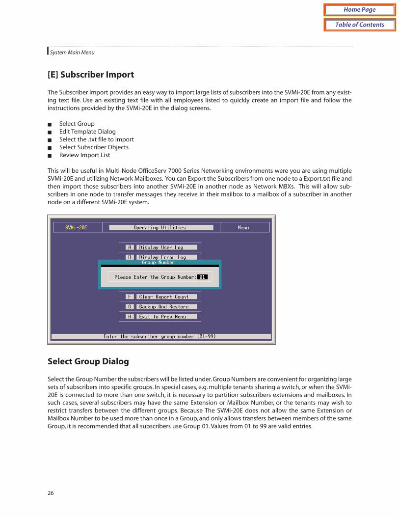
[E] Subscriber Import
The Subscriber Import provides an easy way to import large lists of subscribers into the SVMi-20E from any exist-ing text file. Use an existing text file with all employees listed to quickly create an import file and follow theinstructions provided by the SVMi-20E in the dialog screens.
Select GroupEdit Template DialogSelect the .txt file to importSelect Subscriber ObjectsReview Import List
This will be useful in Multi-Node OfficeServ 7000 Series Networking environments were you are using multipleSVMi-20E and utilizing Network Mailboxes. You can Export the Subscribers from one node to a Export.txt file andthen import those subscribers into another SVMi-20E in another node as Network MBXs. This will allow sub-scribers in one node to transfer messages they receive in their mailbox to a mailbox of a subscriber in anothernode on a different SVMi-20E system.
Select Group Dialog
Select the Group Number the subscribers will be listed under. Group Numbers are convenient for organizing largesets of subscribers into specific groups. In special cases, e.g. multiple tenants sharing a switch, or when the SVMi-20E is connected to more than one switch, it is necessary to partition subscribers extensions and mailboxes. Insuch cases, several subscribers may have the same Extension or Mailbox Number, or the tenants may wish torestrict transfers between the different groups. Because The SVMi-20E does not allow the same Extension orMailbox Number to be used more than once in a Group, and only allows transfers between members of the sameGroup, it is recommended that all subscribers use Group 01. Values from 01 to 99 are valid entries.
System Main Menu
26

Edit Template Dialog
This dialog provides directions for importing subscribers. Make sure the Template Mailbox and Extension Blocksare set up BEFORE importing the subscribers. The SVMi-20E will set up the imported subscriber extensions andmailboxes using these Blocks. This reduces the amount of work needed later on to set these Blocks up one-by-one for each subscriber.
The file used to import the subscribers can be any name but MUST have a .txt extension <export.txt>.
System Main Menu
27

Select Subscriber Objects Dialog
This facility allows easy importation of a large number of subscribers. In the selection field enter either:
E for ExtensionsM for MailboxesB for Both EXT & MBX N for Network MBX
Create a text file, or use any existing text file, to import subscribers. The file can be named user.txt and includeseparate columns for the user name, extension, and/or mailbox. Only the subscriber list may be in the file. Theuser.txt file can look like:
Sandy Parks 217 217Dusty Roads 222 202Sonny Skies 227 007Jane Doe 201John Doe 202
System Main Menu
28

Review Import List Dialog
Scroll through, and review, the subscriber list. The list may not be edited at this point. Accept it as is and pressENTER or reject the list and press the ESC key. All editing that may need to be done on the subscriber list must bedone in the text file the list was created in.
[F] Clear Report Count
This clears all report counters. Report counters can be found throughout the SVMi-20E block definitions and onthe Status Screen. This will not clear the total run time display in System Wide Parameters.
[G] Backup & Restore and FTP
The Backup and Restore on the SVMi-20E is performed through the LAN connector. You can backup to a PChooked directly to this connector using a Crossover cable or to a PC on the customer's Local Area Network usinga straight through cable.
This utility simply shuts down the SVMi-20E and automatically engages the Built in FTP Server software. The SVMSoftware must be shut down in order to run the FTP Server software, which means it is not processing any callswhile the backup is being performed.
There is a separate Backup and Restore utility program called SVMBackup that must be loaded on the directlyattached PC or on the Client PC attached to the Local Area Network. You could also use FTP to simply copy thefiles you want to backup onto a drive on the network. To use FTP you must have your own FTP Client Software.
When your Backup is completed and you want to put the SVM back on line, simply press the red reset button oruse MMC-740 or MMC-806 to reset the SVM card. Any of these methods will terminate the FTP Server and restartthe SVM.
[H] Exit to Prev Menu
Returns to the System Main Menu.
System Main Menu
29

[H] PORT ACTIVITYThe Port Activity Monitor is an extremely useful tool for diagnosing problems on an installed SVMi series system.This screen will display all activity in real time as it happens and is also being broken up and written to the Activity,User, and Error Logs simultaneously. This activity contains detailed information for both, Subscriber and PublicCaller, call sessions. The viewable Monitors are Monit, CP, and Debug. When a system is restarted only the Monitmonitor is on.
This area is a command line driven utility. Pressing [F1] after entering Port Activity will list all the commands weallow the Dealers and End User Administrators to use.
The following commands can be typed in at the => prompt to determine how much and what type of informa-tion is displayed:
Port Activity Commands
ACTIVITY: Displays the Activity Log. This is also the same view that can be seen from the Operating UtilitiesMenu. It is some times more convenient to enter it from Port Activity.Syntax: ACTIVITY
CP: Turns the Call Progress monitor on or off for one or all ports. When watching the port activityscreen, the data preceded with a CP represents data reported by the Call Progress monitors. Thismonitor can be used alone or with either or both the Monit and debug Monitors.Syntax: CP [port|ALL|OFF]
DEBUG: Turns the Debugging monitor on or off for one or all ports. This is useful when experiencinghard to detect problems.
Often you will need to leave this monitor and the CP monitor on and let the system run for awhile. You can then follow the reported information in the Activity, User, and Error Logs for trou-ble shooting purposes. Leaving all the monitors on all the time will cause the time period storedin the logs to be shorter because there is so much more information being reported.
When watching the port activity screen or looking through the log files, the data preceded by aDB represents the data the DEBUG monitors reported. The information reported by the Debugmonitor is often cryptic, but is very useful for the software engineer's when their assistance isrequired in troubleshooting a problem.
This monitor can be used alone or with either or both the Monit and debug Monitors.Syntax: DEBUG [port|ALL|OFF]
DISPLAY: Loads the file specified by name into the File Display Facility. The file must be an ASCII format-ted text file in order to be properly viewed. When specifying the {filespec} you must include thefull DOS path along with the full file name if it is not in the DTA directory [drive:\path\file-name.ext]. Using the FILES command and highlighting a file and then pressing [V] often is eas-ier if you have a few files you want to see and bounce between. Neither of these methods ofviewing the contents of a file will allow you to edit it.Syntax: DISP {filespec}
System Main Menu
30

ERROR: Displays the Error Log.Syntax: ERROR
EXITALL Forces the SVMi to perform an immediate shutdown, and returns the cursor to the DOS com-mand prompt. This will not wait for ports to clear and will terminate any existing calls inprogress.Syntax: EXITALL
FILES: Allows copying, renaming, viewing, and deleting files. You can use the Files command similarlyto using the DIR command in DOS, [drive:\path\filename.ext]. The asterisk [*] can be used as awild card within the filename and/or extension.Syntax: FILES {file spec}
Example: FILES c:\dta\*.log(this will display all files in the DTA directory with an extension of .LOG)
IPC: Turns on/off monitoring system communication messages for all or specific ports. Must beturned off with "OFF" command-not done by maintenance. It may be used in combination withany of the other monitors.Syntax: IPC [port|ALL\Off]
LOCK: Will busy out a port(s), when in goes idle. You can view which ports have been forced into alocked condition Syntax: LOCK [port|ALL]
LOGOFF: Hangs up the RMATS modem port.Syntax: LOGOFF
MAC: From Port Activity you can type “mac” to have the system’s MAC address temporarily displayedon the screen. The MAC Address is also always displayed on Page One of System WideParameters.The MAC address is required for ordering a License Key to unlock a number of E-MailGateway Subscriber Mailboxes.
MAINTENANCE: Schedules daily system maintenance to begin at the first available opportunity.Syntax: MAINT
MESSAGE: Lists the messages in a group by owner. Group defaults to 01 if not specified.Syntax: MESS [group]
Displays a list of all message files in the form:Recipient Name (from Mailbox Label) Sender Name (blank if public or unknown) Date and Time Sent Type (V - Voice) Message Status (Saved, New) Filename
MONITOR: Turns the Activity monitor on or off for one or all ports.Syntax: MONIT [port|ALL|OFF]
System Main Menu
31

NET: The net command is used in two ways:
1. To show the current status of the SVMi network connection at the very moment you typedNET and hit the [enter] key.
2. Typing ‘net ON’ or ‘net OFF’ will toggle the state of network traffic reporting as it pertains tothe SVMi.
RX: Used to prepare the SVMi to be ready to receive a file from the terminal device connected to theSIO connector. When specifying the {filespec} you must include the full DOS path along with thefull file name if it is not in the DTA directory [drive:\path\filename.ext].Syntax: RX {filespec}
SERIAL: List block serial numbers by block type.Syntax: SERIAL [block type]
SHELL: Halts/Suspends system operations and executes a DOS command or brings you to a DOSprompt.
By using the SHELL command by itself you can temporarily exit to a DOS shell. To return to thePort Activity Screen after running the Shell in this fashion you must type EXIT from the DOSprompt.Syntax: SHELL [DOS command]DO NOT run SHELL if attached via the LAN connector
STATUS: Displays port status, available memory and hard drive space.Syntax: STAT
STOP: Stops a port and puts it in the idle state.Syntax: STOP [port]
TX: Used when trying to transmit a file from the SVMi to the terminal device connected to the SIOconnector. XMODEM is the preferred transmit protocol. When specifying the {filespec} youmust include the full DOS path along with the full file name if it is not in the DTA directory[drive:\path\filename.ext].Syntax: TX {filespec}
UNLOCK: Returns a locked port to the idle state.Syntax: UNLOCK [port]
USER: Displays the User Activity Log.Syntax: USER
Port Activity Facility HELP There are two pages of help screens immediately available to the SystemAdministrator.To access the help screens, press F1 to bring up the first page of help and page up or down to movebetween the two pages. The help screens provide information on commands to control and monitor the SVMi-20E' ports.To execute a command, type the command and arguments at the command line prompt => and thenpress ENTER. To exit the facility and return to the System Main Menu, press [Ctrl]+[E].
You may be asked to access this screen by Samsung Technical Support.
System Main Menu
32

System Main Menu
33

[I] OVERRIDE MODEThe Override Mode bypasses control of the Schedule Table. This allows the System Administrator to immediatelyput a single port or group of ports in a specific mode.This override will stay active, on the specified ports, until theSystem Administrator reasserts the automatic schedule. The Override Mode can be activated remotely by theSystem Administrator. See Manual Mode Selection.
The Override Mode has one page which contains all parameters. The parameters are grouped by category as fol-lows:
PORTS This parameter specifies which port(s) are to be set active to a specific Mode Block. Entering "All" in thisfield would assert a Mode Block to all ports.
USE MODE This field is used to pick which Mode Block is to be asserted. To select a Mode, press ENTER to bringup the Target Generator pick list. Select the appropriate Mode and press ENTER. Press F10 to review or edit theselected Mode.
PORT : MODE COLUMN This field shows the controlling Mode Block for each of the active ports on the system,as well as those ports that are controlled by the schedule. It will reflect the changes made in the 'Ports' and 'UseMode' entries.
System Main Menu
34

[J] VIEW SYSTEM REPORTS
Management Information
The SVMi-20E architecture provides a large number of counters to track specific events occurring in an applica-tion and on a system wide basis, this allows an administrator to quickly view activity and parameter value settings.
The SVMi-20E offers activity data and parameter value settings that provide management information on volumeof calls, call connect time, messaging status, and resource utilization.
Note that there are many applications that may be created that introduce complexity to the reporting process.For instance, blind transfers will cause a call record when the SVMi-20E answers and then another record whenthe station forwards or recalls (2 records for 1 call). Also the calculations are made by each module of softwareand may seem to be inconsistent if a comparison to another statistic is assumed. For this reason, we suggest youuse these reports as a guideline only or to observe trends over time. We can explain how each number is gener-ated, but because each application is different we may not be able to explain apparent inconsistencies.
System Main Menu
35

By Application (Call Distribution)
Displays call activity by application type.
REPORTING Indicates the report period. This is the date beginning when the Report Counters were last clearedand ending at the current date.
CREATED The date and time the report was actually created.
CALLS The total number of calls serviced by an application type. One caller accessing more than one applica-tion, such as Voicemail and Fax Applications (two applications), counts as two callers.
MINUTES Total minutes callers were connected to an application type.
% TT The total percentages of callers connected to an application type.
APPLICATION CALL DISTRIBUTION A bar chart of the different applications and the percentages of calls eachapplication serviced. IntraAppls is Intra-application which represents the callers who accessed more than onetype of application.
System Main Menu
36

To Subscribers (Call Distribution)
Displays call activity at subscriber's extensions.
REPORTING Indicates the report period. This is the date beginning when the Report Counters were last clearedand ending at the current date.
CREATED The date and time the report was actually created.
SUBS CALLS The total number of calls to the subscriber's extensions, listed by how the calls were handled (com-pleted, redirected, rejected, etc.).
CALLS TO SUBSCRIBERS - EXTENSIONS A listing of how all calls to the subscribers were handled and their per-centages. For example, 9% of all calls to subscribers were cases where the subscriber's extension was busy.
TOT SUBSCALLS The total number of calls to the subscriber's extensions.
CALLER HOLD TIME The total number of minutes callers were on hold.
System Main Menu
37

Message Activity (Call Distribution)
Displays call activity for public callers and subscribers in Mailboxes.
REPORTING Indicates the report period. This is the date beginning when the Report Counters were last clearedand ending at the current date.
CREATED The date and time the report was actually created.
ACTIVITY The Message Activity types. Several different categories are shown.
PUBLIC The first column is the total number of public callers that accessed a particular type of Message Activity.The second column is the percentage of public callers out of the total number of callers, including subscribers,that accessed a particular type of Message Activity.
SUBSCRIBER The first column is the total number of subscriber callers that accessed a particular type of MessageActivity. The second column is the percentage of subscriber callers, out of the total number of callers, includingpublic callers, that accessed a particular type of Message Activity.
TOTALS The total number of all callers that accessed a particular type of Message Activity.
System Main Menu
38

By Call Code (Call Distribution)
Displays activity by all types.
REPORTING Indicates the report period. This is the date beginning when the Report Counters were last clearedand ending at the current date.
CREATED: The date and time the report was actually created.
CALLS The total number of calls listed by each Call Code.
%TC The percentage of the total count of all calls of a particular Call Code.
MINUTES The total connect time, in minutes, of all calls of a particular Call Code.
PORT UTILIZATION BY CALL CODE A listing of the Call Code types and their port utilization by percentage.
System Main Menu
39

By Hour (Port Utilization)
Displays call activity by each hour of the day.
REPORTING Indicates the report period. This is the date beginning when the Report Counters were last clearedand ending at the current date.
CREATED The date and time the report was actually created.
CALLS The total number of calls that came in during a specific hour.
%TC The percentage of all calls received during a specific hour.
MINUTES The total connect time, in minutes, of all calls during a specific time period.
PORT UTILIZATION BY HOUR A listing of the time periods and their port utilization by percentage.
System Main Menu
40

By Port Number (Port Utilization)
Displays call activity by port (the SVMi-16 with more then 8 ports will require two screens to show the informa-tion for all installed ports. All other products only need one screen. [Ctrl][D] allows you to view page two and[Ctrl][U] allows you to go back to page one.)
REPORTING Indicates the report period. This is the date beginning when the Report Counters were last clearedand ending at the current date.
CREATED The date and time the report was actually created.
CALLS The total number of calls that came in on a specific port.
%TC The percentage of all calls received on a specific port.
System Main Menu
41

MINUTES The total connect time, in minutes, of all calls on a specific port.
PORT UTILIZATION BY PORT NUMBER A listing of the ports and the percentage of calls handled by each portrepresented by a bar chart.
By Day of Week (Port Utilization)
Displays call activity by day of week.
REPORTING Indicates the report period. This is the date beginning when the Report Counters were last clearedand ending at the current date.
CREATED The date and time the report was actually created.
CALLS The total number of calls that came in on a specific day of the week.
%TC The percentage of all calls received on a specific day of the week.
MINUTES The total connect time, in minutes, of all calls on a specific day of the week.
PORT UTILIZATION BY DAY OF WEEK A listing of the days of the week and the percentage of calls handled byeach day, represented by the bar chart.
Exit to Previous Menu (Port Utilization)
Returns to Main Menu.
NOTE: On many Blocks on the system there is also an Activity Page that displays the activity and usage of someof the functionality of that Block. Information on a Blocks Activity Page is explained in a separate technical doc-ument pertaining to that block type.
System Main Menu
42

[K] SITE INFORMATION
This screen menu allows the System Administrator access to helpful information about the site in which the SVMi-20E is installed. This information becomes very useful long after the system installation has been completed.
These are only memo screens but it is recommended that these screens be filled out for all sites. Having a recordof all port connections helps make trouble shooting easier, if it becomes necessary.
[L] STATUS SCREEN
The is the normal operating screen for the SVMi-20E. The Status Screen is a display only facility, and shows infor-mation in real time relating to the current status of the SVMi-20E. The following information is displayed.
To switch between viewing ports 1 - 8 and viewing ports 9 - 16 use [Ctrl]+[D] to go to page 2 (ports 9 - 16) or[Ctrl]+[U] to go back to page 1 (ports 1 - 8).
System Main Menu
43

PORT COLUMN The Port column gives you the number of the voice circuit that the call is taking place on.
MODE COLUMN The Mode Number column lets you know which mode the port is in.
ACTIVE BLOCK COLUMN This column shows you which block is currently servicing the call, as the call getsdirected through the call session.
STATUS COLUMN The status column displays the current condition that the port is in. Some examples are: Idle,Processing, Transferring, Messaging, etc.
System Activity
CALLS TO - DATE The total number of calls that the SVMi-20E has processed.
AVERAGE CALLS PER WEEK The average number of calls per week averaged over all weeks.
DIRECTORY ACCESSES The total number of callers that have accessed the directory.
TIMES ALL PORTS BUSY The total number of times all ports have been busy.
NUMBER OF SUBSCRIBERS The total number of subscribers on the system. This is actually a mailbox count.Extensions are created for every station port on the phone system.
TOTAL MESSAGE COUNT The total number of messages in the system. This includes new and saved messages.
AVG MESSAGES/MAILBOX The average number of messages in the subscriber's mailboxes.
DISK SPACE AVAILABLE The total disk space available in hours and minutes.
System Main Menu
44

2Explanation of Default Configuration
Application Design
Creating an application consists of linking the appropriate Blocks into a set of Call ControlPaths which, for a par-ticular caller, or group of callers, represents a Call Routing Solution.The number of ControlPaths, needed to estab-lish a satisfactory Routing Solution, depends upon how many alternatives or variations the organization wishesto provide, to satisfy the anticipated needs of the caller(s).
The default application is built using Blocks. Each block has a specific purpose and are chained together to buildthe application. This allows the caller to pass from one to the other as the call is processed.
The default configuration in the SVMi-20E has been designed to simplify installation and reduce the amount oftime it takes to learn the application. Many of the programming options have been disabled or fixed at a defaultvalue.
When a call is answered, it is processed by a number of blocks behind the scenes.These blocks are hidden for rea-sons of simplicity. The call is processed in the following way:
NEW CO CALLS New calls are answered by the PORT Block which looks to the SCHEDULE Table to see whichMODE Block should take control of the call session.The MODE Block based on the Call type will then pass controlto one of the MENU blocks. This may have sounded complicated but is quite simple. By default all of the pro-gramming is done for you. Most of the application for the customer actually starts at the MENU Block. Knowledgeof how the call is routed through the system will help you create more complex applications only when and/or ifnecessary.
Depending on the current mode (Day, Night, Holiday, or Weather). A custom Company greeting is played and thecaller is directed to any other block in the system based on the DTMF input.
The below Call Routing Solution Chart shows you the communication links and connections between each of theblocks in the system.
FORWARDED CALLS Follow the same initial call flow as stated above. Their Call Type is identified as a Forwardedcall and the call is passed to a MENU Block that handles forwarded calls. This MENU Block does not speak to thecaller it simply looks at the Forward ID of the Cal and transfers the caller to the appropriate Subscriber's PersonalGreeting. Based on the Subscriber;s greeting the caller may leave a message, route themselves to another sub-
scriber, return to the main men, or simply hang up.
45

Important Basic Concepts
The Programming Concept for the SVMi-20E is a series of Blocks, Pointers, and Objects configured together to cre-ate a "Call Routing Solution" for specific Member(s) of the "TeleCommunity"
TeleCommunity Anybody and/or anything that needs to communicate with the organizationCommunicate The need to deliver and/or receive informationCall Routing Solution The process in which the SVMi-20E Series products connects the caller to the Person
and/or Device most suitable for communicating with the caller.
The main purpose or goal of the SVMi-20E concept is Immediate, Personalized, Unobstructed Access; Anytime,Anywhere.
Explanation of Default Configuration
46

Blocks
Blocks are the components used to build your individual customer application. All call flow is programmed usingthese blocks. Each block type has a specific function, and can be chained together with other blocks to provide acomplete call processing solution.
There are 19 blocks available in the SVMi-20E. They are the following:
Announcement Block Houses up to 15 minutes of recorded voice information for playback in anaudiotex application. It is associated with and managed by an AudiotexLibrarian.
Audiotex Librarian Block Manages the Announcement Blocks, that together forms its Audiotex Library.On-demand, it finds and plays the caller specified Announcement(s). ManagesAnnouncement Block retention, recording length and authorizations, andcaller replay options. It also controls the caller's path through its library.
Bye Block Speaks a prompt, usually "Good-bye", then terminates the call session.
Dial Block This block is typically used for dial devises such as fax machines and modems,or paging systems. Any device where the power of having the functionality ofa subscriber is not necessary.
Directory Block This is a utility that sets up the necessary parameters used in the subscriber'sdirectory list.
Document Librarian Block Manages the Fax Blocks, that together forms its FAX or Document Library. On-demand, it finds and faxes back to the caller specified Fax(s). Manages FaxBlock retention, recording length and authorizations, and caller replay options.It also controls the caller's path through its library.
EClass Block This is a class of service block for extensions, and contains additional permis-sions that apply to all extensions in this class.
Extension Block Represents the subscriber to a caller. Houses subscriber's settings, personalgreetings, and call coverage controls such as call blocking and screening.Contains Caller Option Processor and Designated Location facility for routingcallers to subscriber's current telephone, regardless of physical location.
Multiple subscribers, each with their own Extension Object, can effectivelyshare a single telephone.
Fax Block Associated with Fax-On-Demand applications and is used in conjunction withthe Document Librarian.
List Block Delivers recorded voice message to a list of mailboxes. May contain other listsas members.
Mailbox Block Receives, records, sends, and stores multimedia messages. Contains defaultpersonal greeting, name and password for the subscriber. This block containsall the parameters for the mailbox including pager and cell phone notification.One usually exists for each phone on the system.
MClass Block This is a class of service block for Mailboxes, and contains additional permis-sions that apply to all Mailboxes in this class.
Explanation of Default Configuration
47

Menu Block Speaks prompts to caller and routes on Input from caller entry. The AutoAttendant Main Menu is an example of a menu block.
Mode Block Answers incoming calls for assigned port(s) by mode, as assigned in theSchedule Table. Collects and stores CallData in appropriate call sessionMemory Registers. Can speak salutation prompts.
Net Mailbox Block Receives, records, and sends, multimedia messages. Contains default personalgreeting, name and password for the subscriber. This block contains all theparameters for the subscriber's mailbox that would reside in another system.Follows the AMIS standard.
Port Block Contains all parameters to connect and communicate with the device theSVMi-20E is directly attached to. For most applications changes to this blockare not required. It has been made visible because it contains parameters thatdefine what disconnect signal, besides the switch's IPC disconnect Message,we will hang-up on. This is useful when the CO does not provide a consistentdisconnect.
Query Block Speaks a question/statement and expects to record a voice and or DTMFresponse. Delivers recorded response to one or more mailboxes for transcrip-tion.
Speak Block The purpose of a Speak Block is to speak a prompt or system information tothe caller. A Speak Block can contain two prompts in addition to the ability ofspeaking system information or register contents. After speaking to the caller,control is passed to another Block based on the target of the NEXT pointer .
Station Block The station block is responsible for dialing. When the SVMi-20E dials or trans-fers any calls it uses a station block. All devices accessible via Touch-Tone dial-ing in the SVMi-20E use at least one of these. Each contains the call progress
information to monitor and process calls to the associated device(s).
Explanation of Default Configuration
48

Extension and Mailbox Objects
On the SVMi-20E Subscribers are defined by both extension blocks and mailbox blocks.
The extension block is responsible for playing the appropriate personal greeting, and performing all transfers. Itmay initiate any hold conditions, park and page and other caller options. Through the access manager you cancontrol call screening, forwarding and blocking, find me and follow me. It is the main component that callers willexperience when they dial an extension number and it provides the subscriber with a collection of managementtools and personal services including workload manager, availability schedule, stored phone numbers and directcalling.
The mailbox block, is far more simple. It is used primarily for two things.
Recording messages and notification (Alert and Pager).Each subscriber may have one or both blocks.
Call Directors
Call Directors are powerful tools used to connect the various blocks together. All blocks that pass control of thecall to another block use Call Directors. Call Directors pass control of the call to the next block. Which block theypass control to is dependent on certain conditions called events, that have occurred within the current block.
Events may include no entry, invalid entry, no message left, operator requested and user exit.There are many pos-sible events and they will vary depending on the type of block being programmed.
In a Menu Block, the Call Director is called the 'Menu Input Processor' and also acts on data entered by the caller.In an Extension Block, the Call Director is called the 'Caller Options Processor' and also acts on data entered by thecaller.
In a Mode Block, the Call Director is called the 'Call Code Processor' and also acts on call type data received fromthe phone system.
The Bye Block and the Station Block do not have Call Directors, as they are considered the end of a Call ControlPath.
Event Pointers
The Call Director uses EVENT POINTERS to pass control of the call to the next block. All Event Pointers consist ofan INPUT value, an ACTION, a Block TYPE, and a TARGET.
The INPUT value is the collection of digits, whether received from the caller via DTMF, or telephone system or net-work integration information, collected in the block.
The ACTION is that which takes place when input from the caller equals the INPUT value.
TYPE, is the type of Block to pass control to, there are five types of ACTIONS: GOTO, TRANSLATE, PASSWORD thenGOTO, SEARCH ON, and FILE.
The TARGET is the Name of the Block to pass control to next.
Explanation of Default Configuration
49

Modes
At any time of the day the SVMi-20E system is in a specific operating mode. This may be as simple as Day Mode(business hours) or Night Mode (business closed) or it can be very complex (Special Mode for Port 2 Only, on July19th between 7 and 8 p.m.). New modes may be added as needed. The times that operating modes are effectiveare defined in the Schedule Table. The behavior of the SVMi-20E when it answers a new call during each specificoperating mode is defined in the Mode Block.
The SVMi-20E can be made to change modes either manually, by using Special Administrative commands, orautomatically as specified in the Schedule Table.
Mode Specific Event Pointers
When programming any block that defines event targets (exit points from the block) the SVMi-20E will first askyou to select a mode. This allows the exit destinations to be different for each mode.
For example, the next pointer might access an announcement informing callers of special daytime sales eventsduring the 'Day' Mode, but after 5:00 p.m., it would pass control to a different announcement about evening shop-ping hours, during 'Night' Mode.
Pointers set in the 'Default' mode are always in effect unless the same pointer is set in another Operating Mode.The SVMi-20E will display 'Default' mode pointers in a block while viewing pointers in another mode.The 'Default'mode pointers will be grayed out to denote that they are not in the current mode.
Each Operating Mode is given an unique number by the system. Valid numbers are 01-99, and are assigned insequence as new modes are created. Pressing ENTER at this field opens a Pointer Mode Target Generator, fromwhich an existing mode name may be selected, or a new name may be entered. Entering a new name creates anew Mode with its corresponding Number.
The mode number and name are associated with the block's pointers, not the block itself. This allows one blockto route calls to different destinations in different modes, using different Targets for the pointers' various modereferences.
Template Blocks
To simplify creating multiple blocks of a given type, the SVMi-20E provides a template for each type of block.Templates have default values preset for many of their parameters. You may change these defaults and save themodified Template, or by using the 'Save As...' option , create a new block of that type, while preserving the orig-inal template. Each time a block is created, it will be initialized with the parameter values which are set in the tem-plate. This is particularly useful when building mailbox and extension blocks for subscribers, where many of theparameter settings will be uniform from subscriber to subscriber.
Explanation of Default Configuration
50

3Appendix
Special Characters Used When Writing Dialing Instructions
These characters perform special functions when embedded in any dialing string:
& - This is a flash-hook which is critical for signaling on analog systems.
, - The comma is a one second pause.
\ - The backslash is a four second pause.
T - "T" tells the port to switch to tone (DTMF) dialing. This is the default.
W - Wait for answer. On encountering this character, the SVMi-20E will monitor the line for an answer fromthe called station before dialing any additional characters. If no answer is detected within 6 ring back cyclesor 3 busy cycles, the call will be recalled.
; - The semicolon is wait for dial tone. The SVMi-20E will wait up to twelve seconds for dial tone before dial-ing any additional characters. If no dial tone is detected the call will fail. This is useful in environments thatmay have a shortage of resources such as a limited number of trunk lines or DTMF receivers.
~di - This is an instruction to dial in band. It is used only in the pager suffix string, and is present to preventconflicts with in band and out of band signaling.
H - Operate the hookswitch. If on hook go off, if off hook go on.
To tell the SVMi-20E to dial the value of a register, you would put a dollar sign ($) in front of the Register variable.i.e.: $C means dial the value stored in the Caller ID Register, $F means dial the value stored in the Forward IdRegister.
Please see the table on next page.
51

52
Appendix
The registers are listed below with their Variable. Below are how they are entered
K = Key Value $K
X = EXtension Number Value $X
C = Caller ID $C
F = Forward ID $F
T = Trunk ID $T
B = Call Back Value $B
E = SVM Port Extension Number $E
N = Number of New Nessages in a Mailbox $N
S = Number of Saved Messages in a Mailbox $S
A = LD Account Code $A
1 = Value stored in Registered 1 $1
2 = Value stored in Register 2 $2
3 = Value stored in Register 3 $3
4 = Value stored in Register 4 $4