surgical technique proximal humeral fracture plate … · the integra proximal humeral fracture...
TRANSCRIPT

SURGICAL TECHNIQUEIntegra® Proximal Humeral Fracture Plate System

Table of ContentsIntroductionProduct Description ........................................................................................................................................................................................ 2Indications ......................................................................................................................................................................................................... 3Contraindications ............................................................................................................................................................................................ 3Warnings and Precautions .............................................................................................................................................................................. 4
Design RationaleLP (Low Profile) Plate ....................................................................................................................................................................................... 5GT (Greater Tuberosity) Plate ......................................................................................................................................................................... 6
LP Plate Surgical TechniqueStep 1: Patient Positioning .............................................................................................................................................................................. 7 Step 2: Exposure ............................................................................................................................................................................................... 7 Step 3: Fracture Reduction and Debridement ............................................................................................................................................. 7 Step 4: Plate Positioning ................................................................................................................................................................................. 8 Step 5: Proximal 3.5mm Screw Insertion ...................................................................................................................................................... 9Step 6: 3.5mm Shaft Screw Insertion ............................................................................................................................................................ 10 Step 7: Final Verification ................................................................................................................................................................................. 11
GT Plate Surgical TechniqueStep 1: Patient Positioning .............................................................................................................................................................................. 12 Step 2: Exposure ............................................................................................................................................................................................... 12 Step 3: Fracture Reduction and Debridement ............................................................................................................................................. 12 Step 4: Plate Positioning ................................................................................................................................................................................. 13 Step 5: Proximal 3.5mm Screw Insertion ...................................................................................................................................................... 14Step 6: 2.7mm Proximal Holes (GT Plate Only) ............................................................................................................................................ 15 Step 7: 3.5mm Shaft Screw Insertion ............................................................................................................................................................ 16 Step 8: Final Verification ................................................................................................................................................................................. 17
Product Information ........................................................................................................................................................................................ 18Instrumentation ............................................................................................................................................................................................... 19
2
Introduction
Joseph Abboud, MDPhilip Duke, MB.BS, FRACS, FA(ORTH)AWilliam Geissler, MDAnand Murthi, MDMark Ross, MB.BS, FRACS, FA (ORTH)A
Caution: Federal law restricts this device to sale by or on the order of a physician or practitioner.
Product Description
The Integra Proximal Humeral Fracture Plate System is composed of left and right Humeral reconstruction plate implants in two options, GT Plate and LP Plate. The GT plate is designed to cover the greater tuberosity and is available in four-hole (91mm) and seven-hole (115mm), and ten-hole (138mm) lengths or sizes. The LP plate is designed to sit lower on the greater tuberosity and is available in three-hole (88mm), six-hole (112mm), and nine-hole (135mm) lengths or sizes. The system will feature 3.5mm locking screws (15-75mm lengths), non-locking compression screws (15-40mm lengths) and non-locking partial thread lag screws (40-75mm lengths)., In addition to, 2.7mm locking screws (10-25mm lengths) are also available.
The Integra Proximal Humeral Fracture Plate is a single component made from stainless steel (SS 316L). The non-locking compression, locking and non-locking partial thread lag screws are made from stainless steel (SS 316L).
Surgical Technique
As the manufacturer of this device, Integra does not practice medicine and does not recommend this or any other surgical technique for use on a specific patient. The surgeon who performs any implant procedure is responsible for determining and using the appropriate techniques for implanting the device in each patient.
3
Indications
The Integra Proximal Humeral Fracture Plate system is designed for fractures and fracture dislocations, osteotomies and non-unions of the proximal humerus. Indications Include:
• Dislocated two-, three-, and four-fragment fractures of the proximal humerus, including fractures involving osteopenic bone• Pseudoarthroses in the proximal humerus• Osteotomies in the proximal humerus
Contraindications • Not indicated for use with acute infections or for children during the growth phase • Screws are contraindicated in: active infection, conditions which tend to retard healing such as blood supply limitations, previous infections, insufficient quantity or quality of bone to permit stabilization of the fracture complex, conditions that restrict the patient’s ability or willingness to follow postoperative instructions during the healing process and foreign body sensitivity. • Cases with malignant primary or metastatic tumors which preclude adequate bone support or screw fixations, unless supplemental fixation or stabilization methods are utilized. • Foreign body sensitivity – where material sensitivity is suspected, appropriate tests should be made and sensitivity ruled out prior to implementations. • These implants are intended as a guide to normal healing, and are NOT intended to replace normal body structure or bear the weight of the body in the presence of incomplete bone healing. Delayed unions or non-unions in the presence of load bearing or weight bearing might eventually cause the implant to break due to metal fatigue. All metal surgical implants are subjected to repeated stress in use, which can result in metal fatigue.

4
Warnings and Precautions
• No metallic surgical implant should be reused. Any metal implant, once used, should be discarded. Even though it appears undamaged, it may already have small defects and internal stress patterns which may lead to fatigue failure.• Correct handling of implant is extremely important. Avoid contouring metallic implants whenever possible. If necessary, or allowed by design, the device should not be bent sharply, reverse bent, notched or scratched. All of these operations can produce defects in the surface finish and internal stress concentrations, which may become the focal point for eventual failure of the appliance.• If metal plates or other metallic devices are to be used together with the Integra Proximal Humeral Fracture Plates, all such devices should be manufactured from a metal that has a similar composition to avert possibility of galvanic corrosion or other metallic reactions.• Correct selection of the implant is extremely important. The potential for success in fracture fixation is increased by the selection of the proper size of the implants. The patient’s anatomy and indication will determine the size of the Integra Proximal Humeral Fracture Plate to be used. The size of the human bones presents limiting restrictions on the size and strength of implants.• Postoperative care is extremely important. The patient must be warned that noncompliance with postoperative instructions could lead to breakage of the implant requiring revision surgery to remove the device.• The use of Integra Proximal Humeral Fracture Plates provides the surgeon a means of bone fixation and helps generally in the management of fractures and reconstructive surgeries. The implants are intended as a guide to normal healing and are NOT intended to replace normal body structure. All metal surgical implants are subject to repeated stress in use which can result in metal fatigue.• Failure to immobilize a delayed union or nonunion of bone will result in excessive and repeated stresses which are transmitted by the body to any temporary internal fixation device prior to the healing of the fracture. Due to normal metal fatigue, these stresses can cause eventual bending or breakage of the device. Therefore, it is important that immobilization of the fracture site is maintained until firm bony union (confirmed by clinical and roentgenographic examination) is established.• Detailed written instructions on the use and limitations of the device should be given to the patient. • While the surgeon must make the final decision on implant removal, whenever possible and practical for the individual patient, fixation devices should be removed once their service as an aid to healing is accomplished, particularly in younger more active patients.• The MR environment presents risks to patients with metal implant. Review of the available literature documents that metal implants may heat resulting in tissue damage and may migrate out of position. They may also cause artifact affecting image quality. Physicians should take these risks into consideration when recommending MRI imaging for patients with metal implants. Note: The Integra Proximal Humeral Fracture Plate System has not been evaluated for safety and compatibility in the MR environment. The Integra Proximal Humeral Fracture Plate System has not been tested for heating or migration in the MR environment.
5
Design Rationale
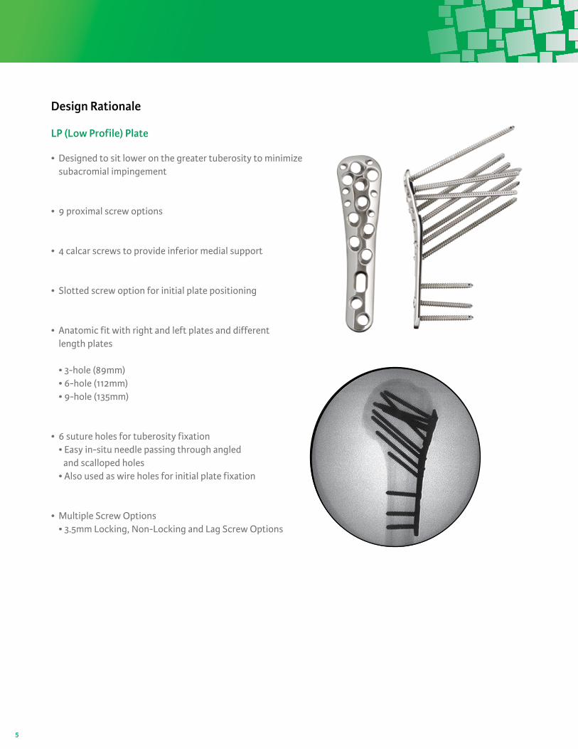
LP (Low Profile) Plate
• Designed to sit lower on the greater tuberosity to minimize subacromial impingement
• 9 proximal screw options
• 4 calcar screws to provide inferior medial support
• Slotted screw option for initial plate positioning
• Anatomic fit with right and left plates and different length plates • 3-hole (89mm) • 6-hole (112mm) • 9-hole (135mm)
• 6 suture holes for tuberosity fixation • Easy in-situ needle passing through angled and scalloped holes • Also used as wire holes for initial plate fixation
• Multiple Screw Options • 3.5mm Locking, Non-Locking and Lag Screw Options
6
Design Rationale
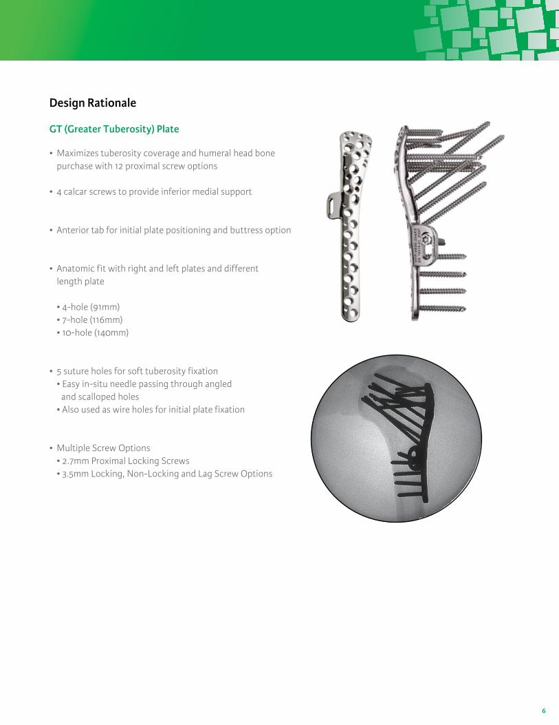
GT (Greater Tuberosity) Plate
• Maximizes tuberosity coverage and humeral head bone purchase with 12 proximal screw options
• 4 calcar screws to provide inferior medial support
• Anterior tab for initial plate positioning and buttress option
• Anatomic fit with right and left plates and different length plate • 4-hole (91mm) • 7-hole (116mm) • 10-hole (140mm)
• 5 suture holes for soft tuberosity fixation • Easy in-situ needle passing through angled and scalloped holes • Also used as wire holes for initial plate fixation
• Multiple Screw Options • 2.7mm Proximal Locking Screws • 3.5mm Locking, Non-Locking and Lag Screw Options
7
Step 1: Patient Positioning
Surgical Technique: LP (Low Profile) Plate
Step 2: Exposure
Step 3: Fracture Reduction and Debridement
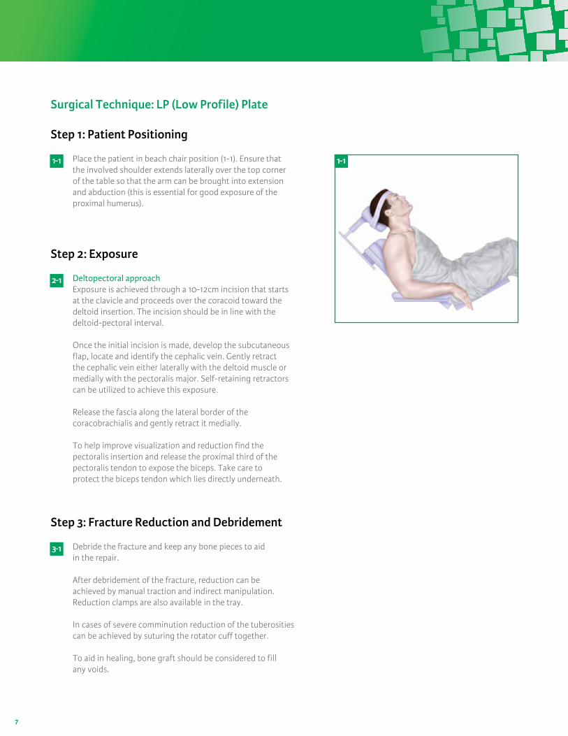
Place the patient in beach chair position (1-1). Ensure that the involved shoulder extends laterally over the top corner of the table so that the arm can be brought into extension and abduction (this is essential for good exposure of the proximal humerus).
Deltopectoral approachExposure is achieved through a 10-12cm incision that starts at the clavicle and proceeds over the coracoid toward the deltoid insertion. The incision should be in line with the deltoid-pectoral interval.
Once the initial incision is made, develop the subcutaneous flap, locate and identify the cephalic vein. Gently retract the cephalic vein either laterally with the deltoid muscle or medially with the pectoralis major. Self-retaining retractors can be utilized to achieve this exposure.
Release the fascia along the lateral border of the coracobrachialis and gently retract it medially.
To help improve visualization and reduction find the pectoralis insertion and release the proximal third of the pectoralis tendon to expose the biceps. Take care to protect the biceps tendon which lies directly underneath.
Debride the fracture and keep any bone pieces to aid in the repair.
After debridement of the fracture, reduction can be achieved by manual traction and indirect manipulation. Reduction clamps are also available in the tray.
In cases of severe comminution reduction of the tuberosities can be achieved by suturing the rotator cuff together.
To aid in healing, bone graft should be considered to fill any voids.
1- 1 1- 1
2- 1
3- 1
8
Step 4: Plate Positioning
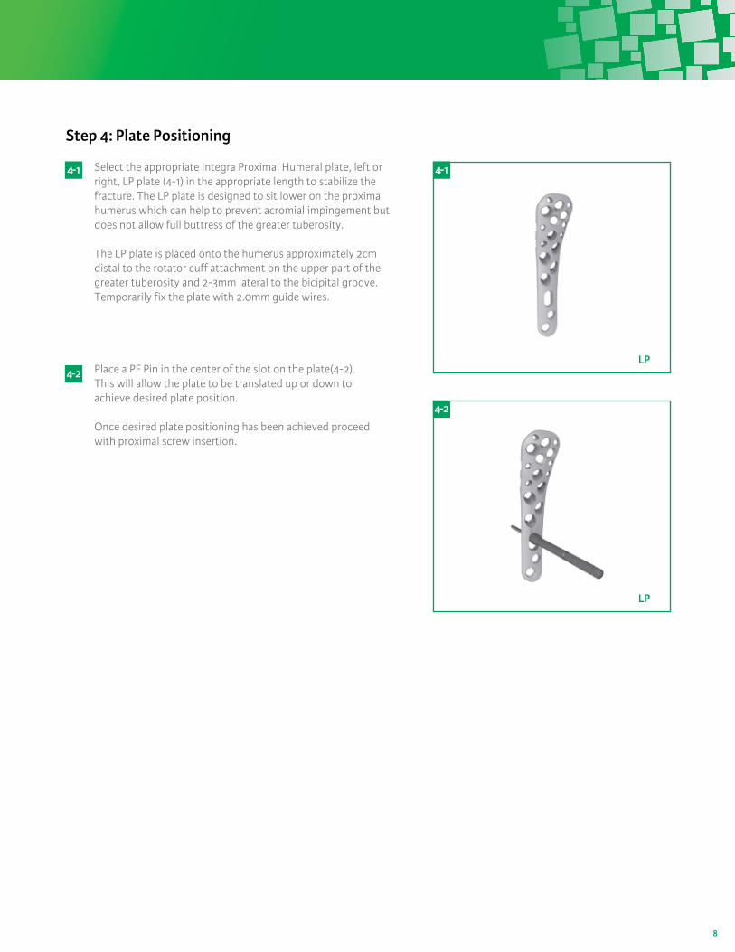
Select the appropriate Integra Proximal Humeral plate, left or right, LP plate (4-1) in the appropriate length to stabilize the fracture. The LP plate is designed to sit lower on the proximal humerus which can help to prevent acromial impingement but does not allow full buttress of the greater tuberosity. The LP plate is placed onto the humerus approximately 2cm distal to the rotator cuff attachment on the upper part of the greater tuberosity and 2-3mm lateral to the bicipital groove. Temporarily fix the plate with 2.0mm guide wires.
Place a PF Pin in the center of the slot on the plate(4-2). This will allow the plate to be translated up or down to achieve desired plate position.
Once desired plate positioning has been achieved proceed with proximal screw insertion.
4- 1
4- 2
4- 1
LP
4- 2
LP
9
Step 5: Proximal 3.5mm Screw Insertion
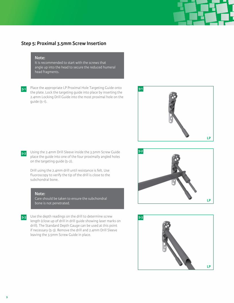
Place the appropriate LP Proximal Hole Targeting Guide onto the plate. Lock the targeting guide into place by inserting the 2.4mm Locking Drill Guide into the most proximal hole on the guide (5-1).
Using the 2.4mm Drill Sleeve inside the 3.5mm Screw Guide place the guide into one of the four proximally angled holes on the targeting guide (5-2).
Drill using the 2.4mm drill until resistance is felt. Use fluoroscopy to verify the tip of the drill is close to the subchondral bone.
Use the depth readings on the drill to determine screw length (close up of drill in drill guide showing laser marks on drill). The Standard Depth Gauge can be used at this point if necessary (5-3). Remove the drill and 2.4mm Drill Sleeve leaving the 3.5mm Screw Guide in place.
5- 1
5- 2
5- 3
5- 1
LP
5- 2
LP
5- 3
LP
Note: It is recommended to start with the screws thatangle up into the head to secure the reduced humeral head fragments.
Note: Care should be taken to ensure the subchondral bone is not penetrated.
10
5- 4
LP
Step 6: 3.5mm Shaft Screw Insertion
The shaft of the plate can be secured by either locking screws or multidirectional non-locking screws.
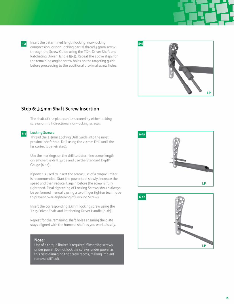
Locking ScrewsThread the 2.4mm Locking Drill Guide into the most proximal shaft hole. Drill using the 2.4mm Drill until the far cortex is penetrated).
Use the markings on the drill to determine screw length or remove the drill guide and use the Standard Depth Gauge (6-1a).
If power is used to insert the screw, use of a torque limiter is recommended. Start the power tool slowly, increase the speed and then reduce it again before the screw is fully tightened. Final tightening of Locking Screws should always be performed manually using a two finger tighten technique to prevent over-tightening of Locking Screws.
Insert the corresponding 3.5mm locking screw using the TX15 Driver Shaft and Ratcheting Driver Handle (6-1b).
Repeat for the remaining shaft holes ensuring the plate stays aligned with the humeral shaft as you work distally.
6- 1
LP
6- 1a
LP
6- 1b
Insert the determined length locking, non-locking compression, or non-locking partial thread 3.5mm screw through the Screw Guide using the TX15 Driver Shaft and Ratcheting Driver Handle (5-4). Repeat the above steps for the remaining angled screw holes on the targeting guide before proceeding to the additional proximal screw holes.
5-4
Note: Use of a torque limiter is required if inserting screws under power. Do not lock the screws under power as this risks damaging the screw recess, making implant removal difficult.
11
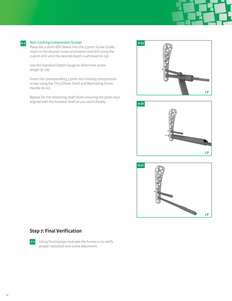
Non-Locking Compression ScrewsPlace the 2.4mm drill sleeve into the 3.5mm Screw Guide, insert in the desired screw orientation and drill using the 2.4mm drill until the desired depth is achieved (6-2a).
Use the Standard Depth Gauge to determine screw length (6-2b).
Insert the corresponding 3.5mm non-locking compression screw using the TX15 Driver Shaft and Ratcheting Driver Handle (6-2c).
Repeat for the remaining shaft holes ensuring the plate stays aligned with the humeral shaft as you work distally.
6- 2
6- 2b
LP
6 - 2a
LP
6 - 2c
LP
Step 7: Final Verification
Using Fluoroscopy evaluate the humerus to verify proper reduction and screw placement.
7- 1
12
Step 1: Patient Positioning
Step 2: Exposure
Step 3: Fracture Reduction and Debridement
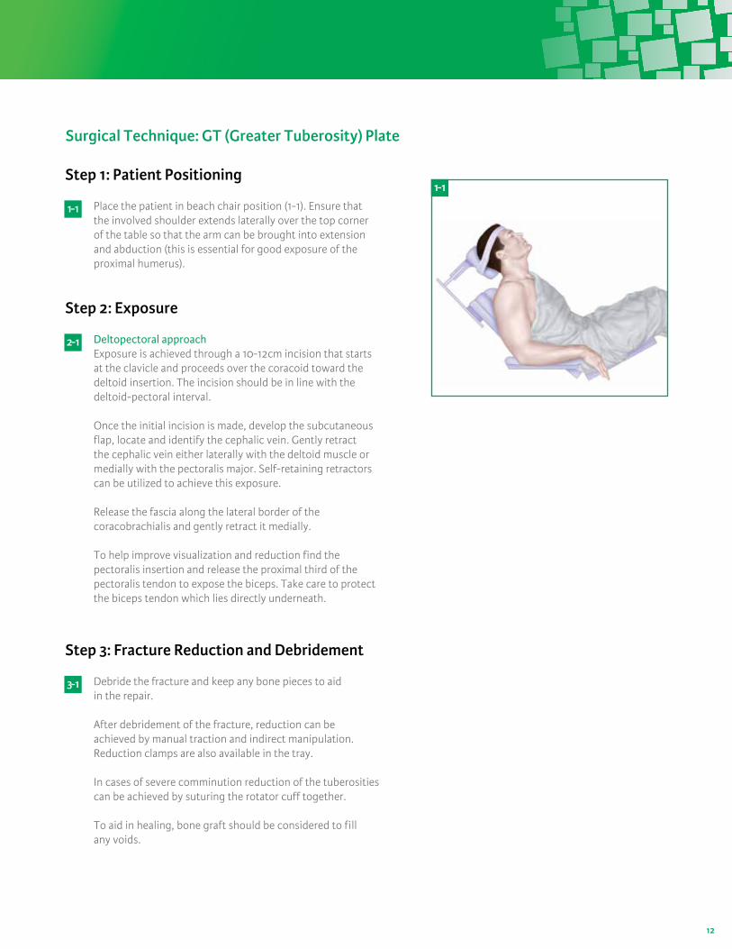
Place the patient in beach chair position (1-1). Ensure that the involved shoulder extends laterally over the top corner of the table so that the arm can be brought into extension and abduction (this is essential for good exposure of the proximal humerus).
Deltopectoral approachExposure is achieved through a 10-12cm incision that startsat the clavicle and proceeds over the coracoid toward the deltoid insertion. The incision should be in line with the deltoid-pectoral interval.
Once the initial incision is made, develop the subcutaneous flap, locate and identify the cephalic vein. Gently retract the cephalic vein either laterally with the deltoid muscle or medially with the pectoralis major. Self-retaining retractors can be utilized to achieve this exposure.
Release the fascia along the lateral border of the coracobrachialis and gently retract it medially.
To help improve visualization and reduction find the pectoralis insertion and release the proximal third of the pectoralis tendon to expose the biceps. Take care to protect the biceps tendon which lies directly underneath.
Debride the fracture and keep any bone pieces to aid in the repair.
After debridement of the fracture, reduction can beachieved by manual traction and indirect manipulation. Reduction clamps are also available in the tray.
In cases of severe comminution reduction of the tuberosities can be achieved by suturing the rotator cuff together.
To aid in healing, bone graft should be considered to fillany voids.
1- 1
2- 1
3- 1
Surgical Technique: GT (Greater Tuberosity) Plate
1- 1
13
Step 4: Plate Positioning
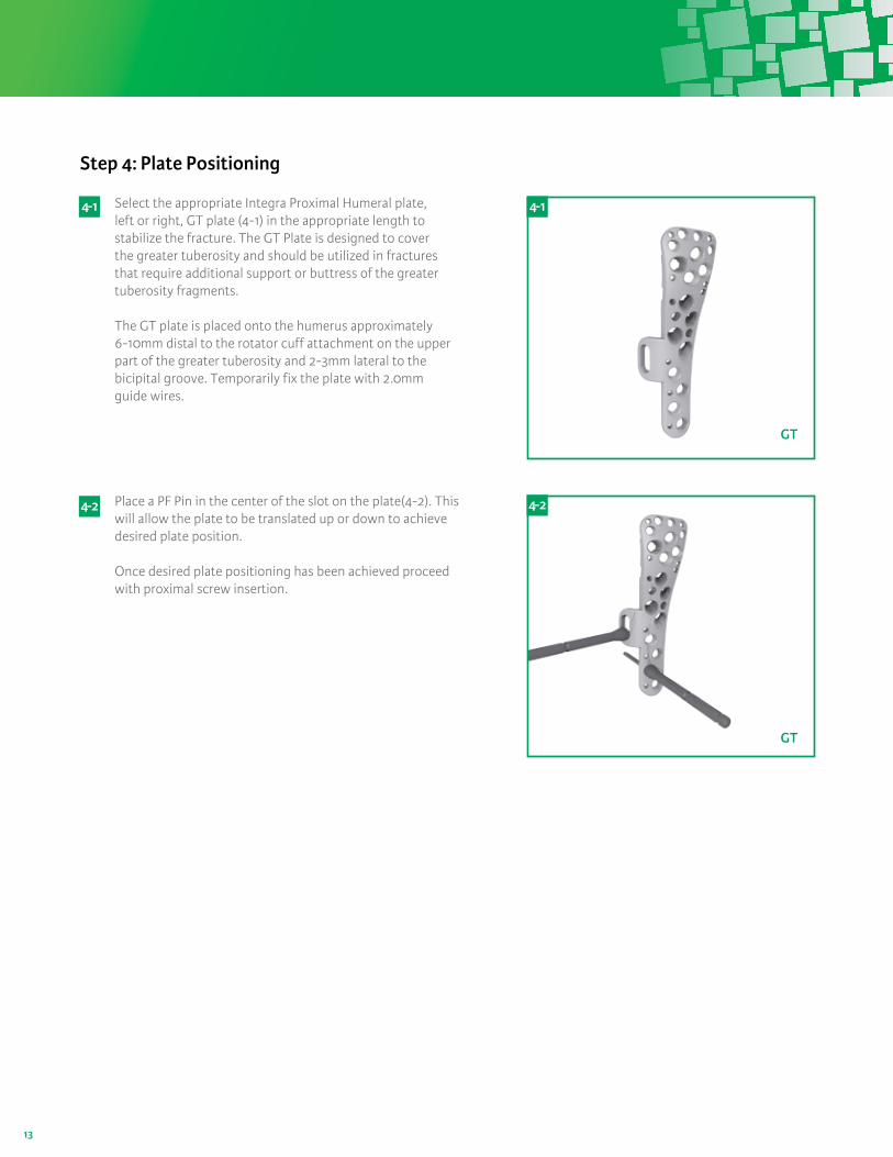
Select the appropriate Integra Proximal Humeral plate,left or right, GT plate (4-1) in the appropriate length to stabilize the fracture. The GT Plate is designed to cover the greater tuberosity and should be utilized in fractures that require additional support or buttress of the greater tuberosity fragments. The GT plate is placed onto the humerus approximately 6-10mm distal to the rotator cuff attachment on the upper part of the greater tuberosity and 2-3mm lateral to the bicipital groove. Temporarily fix the plate with 2.0mm guide wires.
Place a PF Pin in the center of the slot on the plate(4-2). This will allow the plate to be translated up or down to achieve desired plate position.
Once desired plate positioning has been achieved proceed with proximal screw insertion.
4- 1
4- 2
4- 1
GT
4- 2
GT
14
Step 5: Proximal 3.5mm Screw Insertion
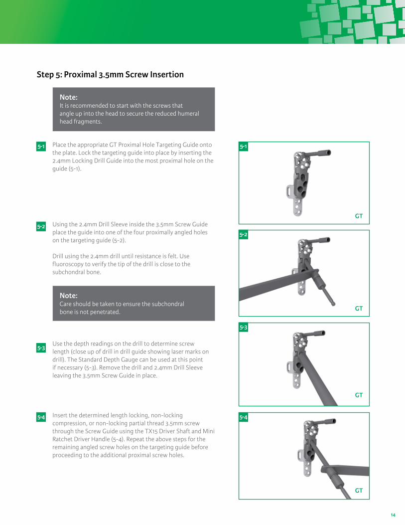
Place the appropriate GT Proximal Hole Targeting Guide onto the plate. Lock the targeting guide into place by inserting the 2.4mm Locking Drill Guide into the most proximal hole on the guide (5-1).
Using the 2.4mm Drill Sleeve inside the 3.5mm Screw Guide place the guide into one of the four proximally angled holes on the targeting guide (5-2).
Drill using the 2.4mm drill until resistance is felt. Use fluoroscopy to verify the tip of the drill is close to the subchondral bone.
Use the depth readings on the drill to determine screw length (close up of drill in drill guide showing laser marks on drill). The Standard Depth Gauge can be used at this point if necessary (5-3). Remove the drill and 2.4mm Drill Sleeve leaving the 3.5mm Screw Guide in place.
Insert the determined length locking, non-locking compression, or non-locking partial thread 3.5mm screw through the Screw Guide using the TX15 Driver Shaft and Mini Ratchet Driver Handle (5-4). Repeat the above steps for the remaining angled screw holes on the targeting guide before proceeding to the additional proximal screw holes.
5- 1
5- 2
5- 3
5-4
5- 1
5- 4
GT
GT
5- 2
GT
5- 3
GT
Note: It is recommended to start with the screws that angle up into the head to secure the reduced humeral head fragments.
Note: Care should be taken to ensure the subchondral bone is not penetrated.
15
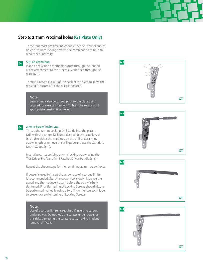
Step 6: 2.7mm Proximal holes (GT Plate Only)
These four most proximal holes can either be used for suture holes or 2.7mm locking screws or a combination of both to repair the tuberosity.
Suture TechniquePlace a heavy non absorbable suture through the tendon at the attachment to the tuberosity and then through the plate (6-1).
There is a recess cut out of the back of the plate to allow the passing of suture after the plate is secured.
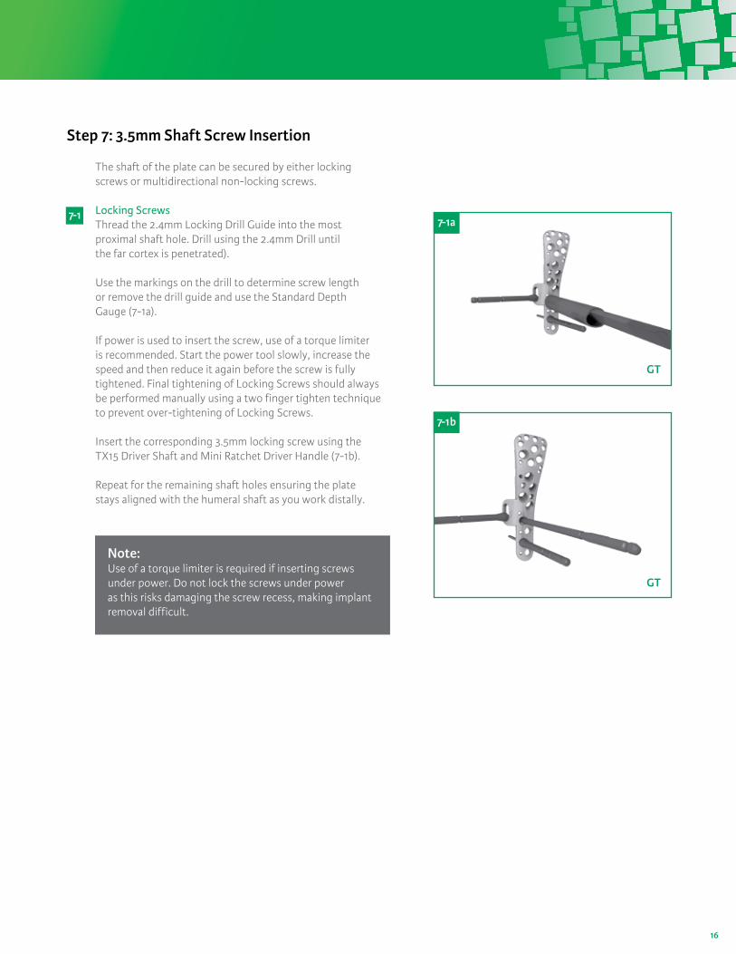
2.7mm Screw Technique Thread the 1.9mm Locking Drill Guide into the plate. Drill with the 1.9mm Drill until desired depth is achieved (6-2). Use either the markings on the drill to determine screw length or remove the drill guide and use the Standard Depth Gauge (6-3).
Insert the corresponding 2.7mm locking screw using the TX8 Driver Shaft and Mini Ratchet Driver Handle (6-4).
Repeat the above steps for the remaining 2.7mm screw holes.
If power is used to insert the screw, use of a torque limiter is recommended. Start the power tool slowly, increase the speed and then reduce it again before the screw is fully tightened. Final tightening of Locking Screws should always be performed manually using a two finger tighten technique to prevent over-tightening of Locking Screws.
6- 1
6-2
6- 1
GT
6- 2
GT
6- 3
GT
6- 4
GT
Note: Sutures may also be passed prior to the plate being secured for ease of insertion. Tighten the suture until appropriate tension is achieved.
Note: Use of a torque limiter is required if inserting screwsunder power. Do not lock the screws under power as this risks damaging the screw recess, making implant removal difficult.
16
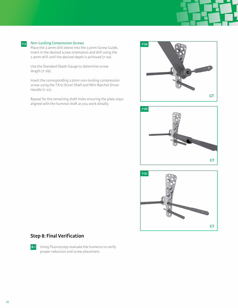
Step 7: 3.5mm Shaft Screw Insertion
The shaft of the plate can be secured by either locking screws or multidirectional non-locking screws.
Locking ScrewsThread the 2.4mm Locking Drill Guide into the most proximal shaft hole. Drill using the 2.4mm Drill until the far cortex is penetrated).
Use the markings on the drill to determine screw length or remove the drill guide and use the Standard Depth Gauge (7-1a).
If power is used to insert the screw, use of a torque limiter is recommended. Start the power tool slowly, increase the speed and then reduce it again before the screw is fully tightened. Final tightening of Locking Screws should always be performed manually using a two finger tighten technique to prevent over-tightening of Locking Screws.
Insert the corresponding 3.5mm locking screw using the TX15 Driver Shaft and Mini Ratchet Driver Handle (7-1b).
Repeat for the remaining shaft holes ensuring the plate stays aligned with the humeral shaft as you work distally.
7- 1
GT
7- 1a
GT
7- 1b
Note: Use of a torque limiter is required if inserting screws under power. Do not lock the screws under power as this risks damaging the screw recess, making implant removal difficult.
17
Non-Locking Compression ScrewsPlace the 2.4mm drill sleeve into the 3.5mm Screw Guide, insert in the desired screw orientation and drill using the 2.4mm drill until the desired depth is achieved (7-2a).
Use the Standard Depth Gauge to determine screw length (7-2b).
Insert the corresponding 3.5mm non-locking compression screw using the TX15 Driver Shaft and Mini Ratchet Driver Handle (7-2c).
Repeat for the remaining shaft holes ensuring the plate stays aligned with the humeral shaft as you work distally.
7- 2
7 - 2b
GT
7 - 2a
GT
7 - 2c
GT
Step 8: Final Verification
Using Fluoroscopy evaluate the humerus to verify proper reduction and screw placement.
8- 1

18
Catalog Number Description Catalog Number Description
Plates
HFP0930304RS Humeral Fracture Plate 4-Hole, RightHFP0930304LS Humeral Fracture Plate 4-Hole, LeftHFP0930307RS Humeral Fracture Plate 7-Hole, RightHFP0930307LS Humeral Fracture Plate 7-Hole, LeftHFP0930310RS Humeral Fracture Plate 10-Hole, RightHFP0930310LS Humeral Fracture Plate 10-Hole, Left
HFP0930103RS Low Profile Humeral Fracture Plate 3-Hole, RightHFP0930103LS Low Profile Humeral Fracture Plate 3-Hole, LeftHFP0930106RS Low Profile Humeral Fracture Plate 6-Hole, RightHFP0930106LS Low Profile Humeral Fracture Plate 6-Hole, LeftHFP0930109RS Low Profile Humeral Fracture Plate 9-Hole, RightHFP0930109LS Low Profile Humeral Fracture Plate 9-Hole, Left
Screws
2.7mm Locking ScrewsPSS2710LS 2.7mm locking screw 10mmPSS2712LS 2.7mm locking screw 12.5mmPSS2715LS 2.7mm locking screw 15mmPSS2717LS 2.7mm locking screw 17.5mmPSS2720LS 2.7mm locking screw 20mmPSS2722LS 2.7mm locking screw 22.5mmPSS2725LS 2.7mm locking screw 25mm
3.5mm Locking ScrewsPSS3515LS 3.5mm locking screw 15mmPSS3517LS 3.5mm locking screw 17.5mmPSS3520LS 3.5mm locking screw 20mmPSS3522LS 3.5mm locking screw 22.5mmPSS3525LS 3.5mm locking screw 25mmPSS3527LS 3.5mm locking screw 27.5mmPSS3530LS 3.5mm locking screw 30mmPSS3532LS 3.5mm locking screw 32.5mmPSS3535LS 3.5mm locking screw 35mmPSS3537LS 3.5mm locking screw 37.5mmPSS3540LS 3.5mm locking screw 40mmPSS3545LS 3.5mm locking screw 45mmPSS3550LS 3.5mm locking screw 50mmPSS3555LS 3.5mm locking screw 55mmPSS3560LS 3.5mm locking screw 60mmPSS3565LS 3.5mm locking screw 65mmPSS3570LS 3.5mm locking screw 70mmPSS3575LS 3.5mm locking screw 75mm
3.5mm Compression ScrewsPSS3515CS 3.5mm compression screw 15mmPSS3517CS 3.5mm compression screw 17.5mmPSS3520CS 3.5mm compression screw 20mmPSS3522CS 3.5mm compression screw 22.5mmPSS3525CS 3.5mm compression screw 25mmPSS3527CS 3.5mm compression screw 27.5mmPSS3530CS 3.5mm compression screw 30mmPSS3532CS 3.5mm compression screw 32.5mmPSS3535CS 3.5mm compression screw 35mmPSS3537CS 3.5mm compression screw 37.5mmPSS3540CS 3.5mm compression screw 40mm
3.5mm Partially Treaded ScrewsPSS3540PS 3.5mm partially threaded screw 40mmPSS3545PS 3.5mm partially threaded screw 45mmPSS3550PS 3.5mm partially threaded screw 50mmPSS3555PS 3.5mm partially threaded screw 55mmPSS3560PS 3.5mm partially threaded screw 60mmPSS3565PS 3.5mm partially threaded screw 65mmPSS3570PS 3.5mm partially threaded screw 70mmPSS3575PS 3.5mm partially threaded screw 75mm
Single Use
DRL501019 1.9mm Drill BitDRL501024 2.4mm Drill BitDRL501035 3.5mm Drill BitWIRE0930501S 2.0mm K-wire–SmoothWIRE0930501T 2.0mm K-wire–ThreadedPFP501024 2.4mm Provisional Fixation Pin09305002 13lb-in Single Use Torque Limiter09305003 4.5lb-in Single Use Torque Limiter
Catalog Number Description
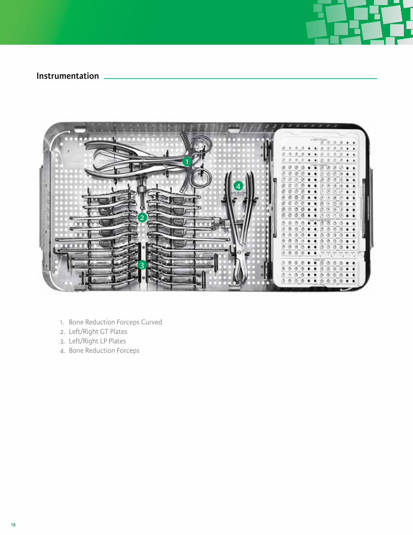
Instruments
LDG501019 1.9mm Locking drill guideLDG501024 2.4mm Locking drill guideDDG501007 2.4mm Drill GuideDDG501008 3.5mm Screw GuideDDG501009 3.5mm Drill Guide5010009 Torx 15 Drive Shaft5010010 Torx 8 Drive ShaftPDG501002 Plate Depth GaugePDG501003 Drill Guide Depth GaugeRM1011S03 Mini Ratchet Driver Handle5010001 AO to Trinkle adapter5010002A Periosteal Elevator 5010008 Bone Reduction Forceps Straight 9” 5010004 Bone Reduction Forceps Curved 8” HTG093003L Left Proximal Hole Targeting Guide–GT PlateHTG093003R Right Proximal Hole Targeting Guide–GT PlateHTG093001L Left Proximal Hole Targeting Guide–LP PlateHTG093001R Right Proximal Hole Targeting Guide–LP PlateCSA00014 Tray LidCSA093001 Tray Base CSA093002 Tray UpperCSA093003 Screw Caddy BaseCSA093004 Screw Caddy Lid
Catalog Number Description
Product Information
19
1. Bone Reduction Forceps Curved2. Left/Right GT Plates3. Left/Right LP Plates4. Bone Reduction Forceps
1
2
3
4
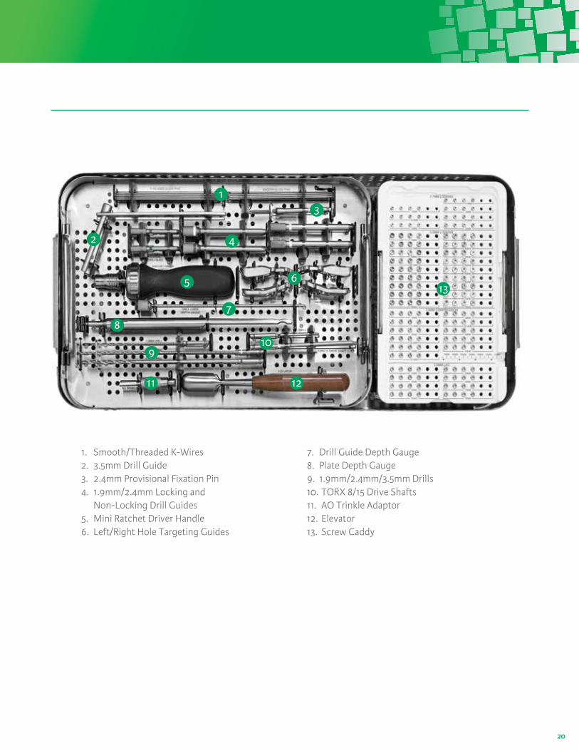
Instrumentation
20
1. Smooth/Threaded K-Wires2. 3.5mm Drill Guide3. 2.4mm Provisional Fixation Pin4. 1.9mm/2.4mm Locking and
Non-Locking Drill Guides 5. Mini Ratchet Driver Handle6. Left/Right Hole Targeting Guides
1
2
3
4
5
7
6
8
910
11 12
13
7. Drill Guide Depth Gauge8. Plate Depth Gauge9. 1.9mm/2.4mm/3.5mm Drills10. TORX 8/15 Drive Shafts11. AO Trinkle Adaptor12. Elevator13. Screw Caddy

21

22

For more information or to place an order, please contact:Integra n 311 Enterprise Drive, Plainsboro, NJ 08536800-444-1122 USA n 609-936-5400 outside USA n 888-980-7742 faxintegralife.com
Integra®
Proximal Humeral Fracture Plate System
Integra and the Integra logo are registered trademarks of Integra LifeSciences Corporation or its subsidiaries in the United States and/or other countries. ©2013 Integra LifeSciences Corporation All rights reserved. Printed in the USA. XK. 00xxxxx