support structures for additive manufacturing: a review
TRANSCRIPT

Manufacturing andMaterials Processing
Journal of
Review
Support Structures for Additive Manufacturing:A Review
Jingchao Jiang , Xun Xu and Jonathan Stringer *
Department of Mechanical Engineering, University of Auckland, Auckland 1142, New Zealand;[email protected] (J.J.); [email protected] (X.X.)* Correspondence: [email protected]
Received: 13 August 2018; Accepted: 19 September 2018; Published: 20 September 2018�����������������
Abstract: Additive manufacturing (AM) has developed rapidly since its inception in the 1980s. AM isperceived as an environmentally friendly and sustainable technology and has already gained a lotof attention globally. The potential freedom of design offered by AM is, however, often limitedwhen printing complex geometries due to an inability to support the stresses inherent within themanufacturing process. Additional support structures are often needed, which leads to material,time and energy waste. Research in support structures is, therefore, of great importance forthe future and further improvement of additive manufacturing. This paper aims to review thevaried research that has been performed in the area of support structures. Fifty-seven publicationsregarding support structure optimization are selected and categorized into six groups for discussion.A framework is established in which future research into support structures can be pursued andstandardized. By providing a comprehensive review and discussion on support structures, AM canbe further improved and developed in terms of support waste in the future, thus, making AM a moresustainable technology.
Keywords: additive manufacturing; support structure; waste reduction
1. Introduction
Additive manufacturing (AM), also known as 3D printing, direct digital manufacturing andsolid freeform fabrication, is defined by the joint ISO/ASTM terminology standard to be the “processof joining materials to make parts from 3D model data, usually layer upon layer, as opposed tosubtractive manufacturing and formative manufacturing methodologies” [1]. 3D printing has beenmentioned as a revolution by “The Economist” and others due to its distinctive manufacturingmethod [2]. The origins of additive manufacturing can be traced back to the 1980s, when a series oftechnologies were developed that were able to construct a three-dimensional object directly from asuitably formatted data file in a layer-by-layer fashion [3]. The primary market for these technologieswas in the production of models and prototypes to enable better visualization of designs, and tosee how the designed part would interact with pre-existing parts. As the use of such technologiesreduced the time necessary to make prototypes, the technologies were often referred to as ‘rapidprototyping’ [4].
As rapid prototyping technologies were developed, in particular the ability to additivelymanufacture metal parts, the possibility of using such techniques as a manufacturing process becamehighly appealing. Potential advantages of such a manufacturing approach include a reductionin material waste, decentralization of the manufacturing process and subsequent reduction intransportation and storage costs [5], realization of objects that would be difficult or impossible toachieve by conventional subtractive means [6] and mass customization of components [7]. Due to
J. Manuf. Mater. Process. 2018, 2, 64; doi:10.3390/jmmp2040064 www.mdpi.com/journal/jmmp
J. Manuf. Mater. Process. 2018, 2, 64 2 of 23
these advantages, additive manufacturing is becoming increasingly common and has been applied inmany fields such as aerospace, automotive and industrial applications [8,9].
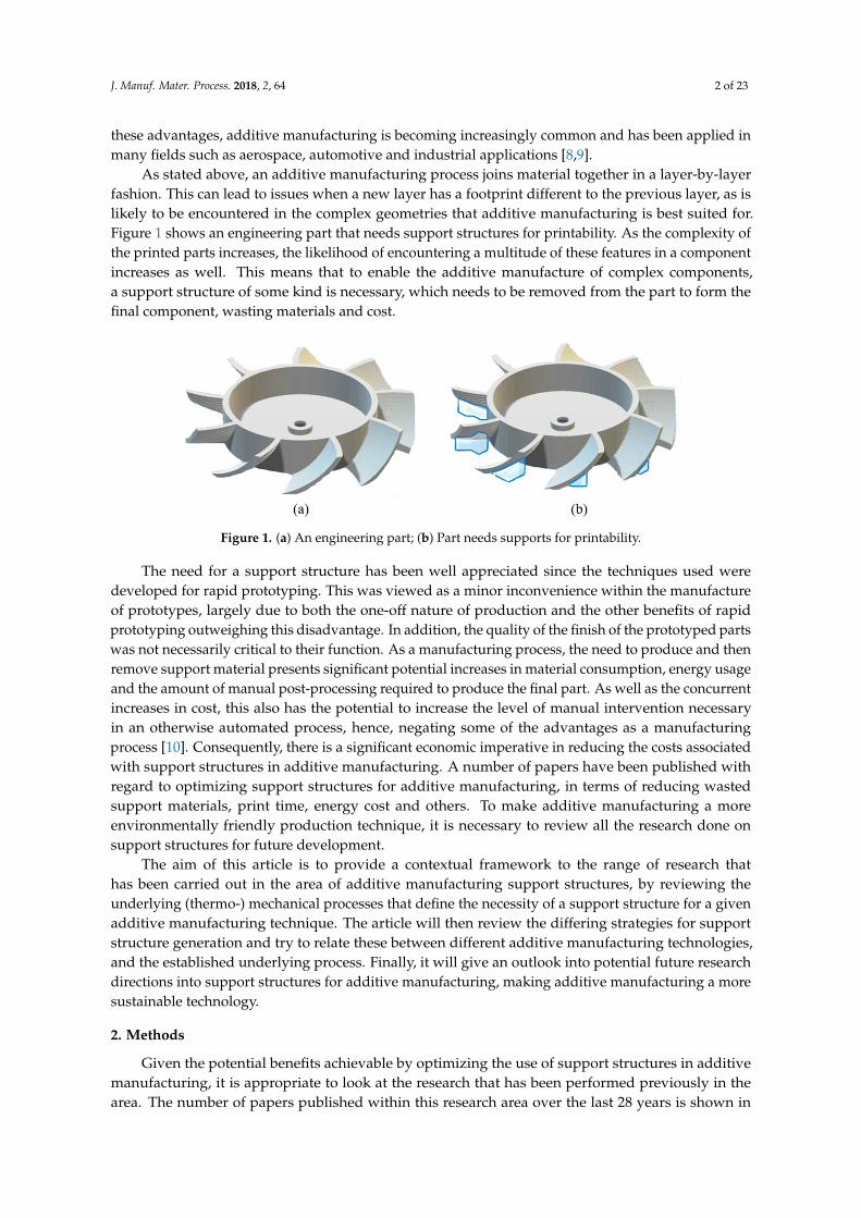
As stated above, an additive manufacturing process joins material together in a layer-by-layerfashion. This can lead to issues when a new layer has a footprint different to the previous layer, as islikely to be encountered in the complex geometries that additive manufacturing is best suited for.Figure 1 shows an engineering part that needs support structures for printability. As the complexity ofthe printed parts increases, the likelihood of encountering a multitude of these features in a componentincreases as well. This means that to enable the additive manufacture of complex components,a support structure of some kind is necessary, which needs to be removed from the part to form thefinal component, wasting materials and cost.
J. Manuf. Mater. Process. 2018, 2, x FOR PEER REVIEW 2 of 23
As stated above, an additive manufacturing process joins material together in a layer-by-layer fashion. This can lead to issues when a new layer has a footprint different to the previous layer, as is likely to be encountered in the complex geometries that additive manufacturing is best suited for. Figure 1 shows an engineering part that needs support structures for printability. As the complexity of the printed parts increases, the likelihood of encountering a multitude of these features in a component increases as well. This means that to enable the additive manufacture of complex components, a support structure of some kind is necessary, which needs to be removed from the part to form the final component, wasting materials and cost.
Figure 1. (a) An engineering part; (b) Part needs supports for printability.
The need for a support structure has been well appreciated since the techniques used were developed for rapid prototyping. This was viewed as a minor inconvenience within the manufacture of prototypes, largely due to both the one-off nature of production and the other benefits of rapid prototyping outweighing this disadvantage. In addition, the quality of the finish of the prototyped parts was not necessarily critical to their function. As a manufacturing process, the need to produce and then remove support material presents significant potential increases in material consumption, energy usage and the amount of manual post-processing required to produce the final part. As well as the concurrent increases in cost, this also has the potential to increase the level of manual intervention necessary in an otherwise automated process, hence, negating some of the advantages as a manufacturing process [10]. Consequently, there is a significant economic imperative in reducing the costs associated with support structures in additive manufacturing. A number of papers have been published with regard to optimizing support structures for additive manufacturing, in terms of reducing wasted support materials, print time, energy cost and others. To make additive manufacturing a more environmentally friendly production technique, it is necessary to review all the research done on support structures for future development.
The aim of this article is to provide a contextual framework to the range of research that has been carried out in the area of additive manufacturing support structures, by reviewing the underlying (thermo-) mechanical processes that define the necessity of a support structure for a given additive manufacturing technique. The article will then review the differing strategies for support structure generation and try to relate these between different additive manufacturing technologies, and the established underlying process. Finally, it will give an outlook into potential future research directions into support structures for additive manufacturing, making additive manufacturing a more sustainable technology.
2. Methods
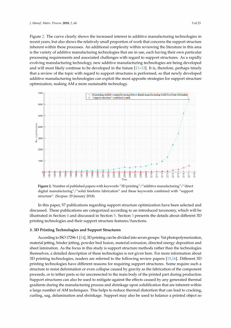
Given the potential benefits achievable by optimizing the use of support structures in additive manufacturing, it is appropriate to look at the research that has been performed previously in the area. The number of papers published within this research area over the last 28 years is shown in Figure 2. The curve clearly shows the increased interest in additive manufacturing technologies in recent years, but also shows the relatively small proportion of work that concerns the support structure inherent within these processes. An additional complexity within reviewing the literature
Figure 1. (a) An engineering part; (b) Part needs supports for printability.
The need for a support structure has been well appreciated since the techniques used weredeveloped for rapid prototyping. This was viewed as a minor inconvenience within the manufactureof prototypes, largely due to both the one-off nature of production and the other benefits of rapidprototyping outweighing this disadvantage. In addition, the quality of the finish of the prototyped partswas not necessarily critical to their function. As a manufacturing process, the need to produce and thenremove support material presents significant potential increases in material consumption, energy usageand the amount of manual post-processing required to produce the final part. As well as the concurrentincreases in cost, this also has the potential to increase the level of manual intervention necessaryin an otherwise automated process, hence, negating some of the advantages as a manufacturingprocess [10]. Consequently, there is a significant economic imperative in reducing the costs associatedwith support structures in additive manufacturing. A number of papers have been published withregard to optimizing support structures for additive manufacturing, in terms of reducing wastedsupport materials, print time, energy cost and others. To make additive manufacturing a moreenvironmentally friendly production technique, it is necessary to review all the research done onsupport structures for future development.
The aim of this article is to provide a contextual framework to the range of research thathas been carried out in the area of additive manufacturing support structures, by reviewing theunderlying (thermo-) mechanical processes that define the necessity of a support structure for a givenadditive manufacturing technique. The article will then review the differing strategies for supportstructure generation and try to relate these between different additive manufacturing technologies,and the established underlying process. Finally, it will give an outlook into potential future researchdirections into support structures for additive manufacturing, making additive manufacturing a moresustainable technology.
2. Methods
Given the potential benefits achievable by optimizing the use of support structures in additivemanufacturing, it is appropriate to look at the research that has been performed previously in thearea. The number of papers published within this research area over the last 28 years is shown in
J. Manuf. Mater. Process. 2018, 2, 64 3 of 23
Figure 2. The curve clearly shows the increased interest in additive manufacturing technologies inrecent years, but also shows the relatively small proportion of work that concerns the support structureinherent within these processes. An additional complexity within reviewing the literature in this areais the variety of additive manufacturing technologies that are in use, each having their own particularprocessing requirements and associated challenges with regard to support structures. As a rapidlyevolving manufacturing technology, new additive manufacturing technologies are being developedand will most likely continue to be developed in the future [11–13]. It is, therefore, perhaps timelythat a review of the topic with regard to support structures is performed, so that newly developedadditive manufacturing technologies can exploit the most apposite strategies for support structureoptimization, making AM a more sustainable technology.
J. Manuf. Mater. Process. 2018, 2, x FOR PEER REVIEW 3 of 23
in this area is the variety of additive manufacturing technologies that are in use, each having their own particular processing requirements and associated challenges with regard to support structures. As a rapidly evolving manufacturing technology, new additive manufacturing technologies are being developed and will most likely continue to be developed in the future [11–13]. It is, therefore, perhaps timely that a review of the topic with regard to support structures is performed, so that newly developed additive manufacturing technologies can exploit the most apposite strategies for support structure optimization, making AM a more sustainable technology.
In this paper, 57 publications regarding support structure optimization have been selected and discussed. These publications are categorized according to an introduced taxonomy, which will be illustrated in Section 4 and discussed in Section 5. Section 3 presents the details about different 3D printing technologies and their support structure features/functions.
Figure 2. Number of published papers with keywords “3D printing”/“additive manufacturing”/ “direct digital manufacturing”/“solid freeform fabrication” and these keywords combined with “support structure”. (Scopus: 29 January 2018).
3. 3D Printing Technologies and Support Structures
According to ISO 17296-1 [14], 3D printing can be divided into seven groups: Vat photopolymerization, material jetting, binder jetting, powder bed fusion, material extrusion, directed energy deposition and sheet lamination. As the focus in this study is support structure methods rather than the technologies themselves, a detailed description of these technologies is not given here. For more information about 3D printing technologies, readers are referred to the following review papers [15,16]. Different 3D printing technologies have different reasons for requiring support structures. Some require such a structure to resist deformation or even collapse caused by gravity as the fabrication of the component proceeds, or to tether parts so far unconnected to the main body of the printed part during production. Support structures can also be used to mitigate against the effects caused by any generated thermal gradients during the manufacturing process and shrinkage upon solidification that are inherent within a large number of AM techniques. This helps to reduce thermal distortion that can lead to cracking, curling, sag, delamination and shrinkage. Support may also be used to balance a printed object so that it is securely tethered to the build platform during manufacture. A comprehensively summarized table shows the details (see Table 1) about different 3D printing processes and its support structure features/functions. Overall, the purposes of support structures can be categorized into three types:
Figure 2. Number of published papers with keywords “3D printing”/“additive manufacturing”/“directdigital manufacturing”/“solid freeform fabrication” and these keywords combined with “supportstructure”. (Scopus: 29 January 2018).
In this paper, 57 publications regarding support structure optimization have been selected anddiscussed. These publications are categorized according to an introduced taxonomy, which will beillustrated in Section 4 and discussed in Section 5. Section 3 presents the details about different 3Dprinting technologies and their support structure features/functions.
3. 3D Printing Technologies and Support Structures
According to ISO 17296-1 [14], 3D printing can be divided into seven groups: Vat photopolymerization,material jetting, binder jetting, powder bed fusion, material extrusion, directed energy deposition andsheet lamination. As the focus in this study is support structure methods rather than the technologiesthemselves, a detailed description of these technologies is not given here. For more information about3D printing technologies, readers are referred to the following review papers [15,16]. Different 3Dprinting technologies have different reasons for requiring support structures. Some require such astructure to resist deformation or even collapse caused by gravity as the fabrication of the componentproceeds, or to tether parts so far unconnected to the main body of the printed part during production.Support structures can also be used to mitigate against the effects caused by any generated thermalgradients during the manufacturing process and shrinkage upon solidification that are inherent withina large number of AM techniques. This helps to reduce thermal distortion that can lead to cracking,curling, sag, delamination and shrinkage. Support may also be used to balance a printed object so
J. Manuf. Mater. Process. 2018, 2, 64 4 of 23
that it is securely tethered to the build platform during manufacture. A comprehensively summarizedtable shows the details (see Table 1) about different 3D printing processes and its support structurefeatures/functions. Overall, the purposes of support structures can be categorized into three types:
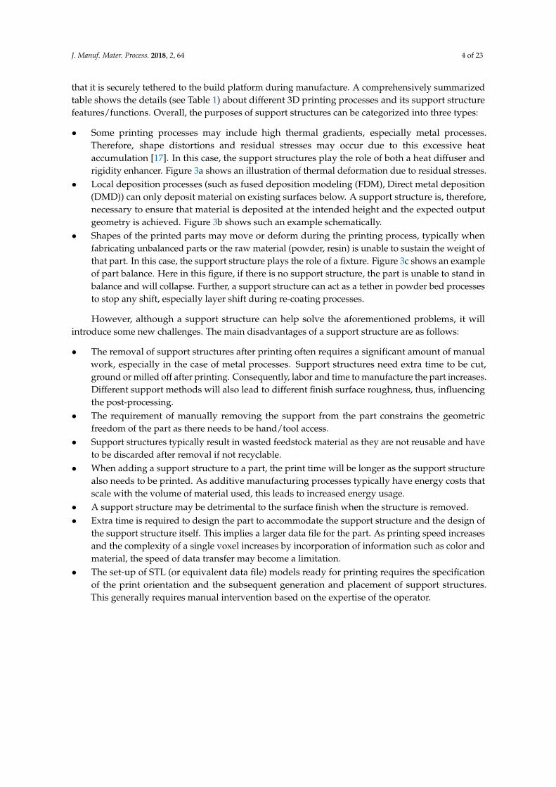
• Some printing processes may include high thermal gradients, especially metal processes.Therefore, shape distortions and residual stresses may occur due to this excessive heataccumulation [17]. In this case, the support structures play the role of both a heat diffuser andrigidity enhancer. Figure 3a shows an illustration of thermal deformation due to residual stresses.
• Local deposition processes (such as fused deposition modeling (FDM), Direct metal deposition(DMD)) can only deposit material on existing surfaces below. A support structure is, therefore,necessary to ensure that material is deposited at the intended height and the expected outputgeometry is achieved. Figure 3b shows such an example schematically.
• Shapes of the printed parts may move or deform during the printing process, typically whenfabricating unbalanced parts or the raw material (powder, resin) is unable to sustain the weight ofthat part. In this case, the support structure plays the role of a fixture. Figure 3c shows an exampleof part balance. Here in this figure, if there is no support structure, the part is unable to stand inbalance and will collapse. Further, a support structure can act as a tether in powder bed processesto stop any shift, especially layer shift during re-coating processes.
However, although a support structure can help solve the aforementioned problems, it willintroduce some new challenges. The main disadvantages of a support structure are as follows:
• The removal of support structures after printing often requires a significant amount of manualwork, especially in the case of metal processes. Support structures need extra time to be cut,ground or milled off after printing. Consequently, labor and time to manufacture the part increases.Different support methods will also lead to different finish surface roughness, thus, influencingthe post-processing.
• The requirement of manually removing the support from the part constrains the geometricfreedom of the part as there needs to be hand/tool access.
• Support structures typically result in wasted feedstock material as they are not reusable and haveto be discarded after removal if not recyclable.
• When adding a support structure to a part, the print time will be longer as the support structurealso needs to be printed. As additive manufacturing processes typically have energy costs thatscale with the volume of material used, this leads to increased energy usage.
• A support structure may be detrimental to the surface finish when the structure is removed.• Extra time is required to design the part to accommodate the support structure and the design of
the support structure itself. This implies a larger data file for the part. As printing speed increasesand the complexity of a single voxel increases by incorporation of information such as color andmaterial, the speed of data transfer may become a limitation.
• The set-up of STL (or equivalent data file) models ready for printing requires the specificationof the print orientation and the subsequent generation and placement of support structures.This generally requires manual intervention based on the expertise of the operator.

J. Manuf. Mater. Process. 2018, 2, 64 5 of 23
Table 1. Characteristics of 3D printing technologies in support structures.
3D Printing Category(ISO, 2015) Definition Technologies Material Used
Does This TechniqueNeed Support Structure?
The Functions of Support Structure
For ThermalDissipation
ForPrintability
For PartBalance
Vat photopolymerization
Liquid photopolymer in avat is selectively cured by
light-activatedpolymerization.
Stereolithography (SLA) [18] Photopolymers Yes√ √
Solid ground curing (SGC) [19] Photopolymers NO
Liquid thermal polymerization(LTP) [20] Thermosetting polymers Yes
√ √ √
Beam interference solidification(BIS)/Holographic interference
solidification (HIS) [20]Photosensitive polymers Yes
√ √
Binder jettingLiquid bonding agent isselectively deposited tojoin powder materials
Three-dimensional printing(3DP) [21] Powder materials Yes
√ √
Material jetting Droplets of build materialare selectively deposited.
Inkjet printing (IJP)/Multijetmodeling (MJM)/Thermojet
[15,22,23]Liquid materials NO
Ballistic particle manufacturing(BPM) [24]
Thermoplastics and metalsthat easily melt and solidify Yes
√ √
Powder bed fusionThermal energy
selectively fuses regionsof a powder bed.
Selective laser melting (SLM)[25]
Powder materials,including stainless steel,tool steel, cobalt chrome,titanium and aluminum
Yes√ √ √
Selective laser sintering (SLS)[26]
Powder materials, includingmetal powders, nylon,
nylon composites, sand,wax, polycarbonates etc.
Generally not necessary,depending on the materialsused. If yes, it is for thermal
dissipation only
√
Direct metal laser sintering(DMLS) [27] Metallic powder only Yes
√
Electron beam manufacturing(EBM) [28] Metal powder Yes
√ √ √
Material extrusionMaterial is selectivelydispensed through a
nozzle or orifice.
Robocasting [29] Ceramic slurry Yes√ √
Fused deposition modeling(FDM) [30] Thermoplastic material Yes
√ √ √

J. Manuf. Mater. Process. 2018, 2, 64 6 of 23
Table 1. Cont.
3D Printing Category(ISO, 2015) Definition Technologies Material Used
Does This TechniqueNeed Support Structure?
The Functions of Support Structure
For ThermalDissipation
ForPrintability
For PartBalance
Directed energy deposition
Focused thermal energy isused to fuse materials bymelting as they are being
deposited.
Direct metal deposition(DMD)/Laser engineered net
shaping (LENS) [31,32]Metal powder Yes
√ √ √
Laser powder deposition (LPD)[33] Powder materials Yes
√ √ √
Selective laser cladding (SLC)[34] Metal powder NO
Sheet laminationSheets of material are
bonded to form an object.
Laminated objectmanufacturing (LOM) [35] Adhesive backed paper NO
Solid foil polymerization (SFP)[20] Semi-polymerized foil NO
J. Manuf. Mater. Process. 2018, 2, 64 7 of 23
J. Manuf. Mater. Process. 2018, 2, x FOR PEER REVIEW 4 of 23
• Some printing processes may include high thermal gradients, especially metal processes. Therefore, shape distortions and residual stresses may occur due to this excessive heat accumulation [17]. In this case, the support structures play the role of both a heat diffuser and rigidity enhancer. Figure 3a shows an illustration of thermal deformation due to residual stresses.
• Local deposition processes (such as fused deposition modeling (FDM), Direct metal deposition (DMD)) can only deposit material on existing surfaces below. A support structure is, therefore, necessary to ensure that material is deposited at the intended height and the expected output geometry is achieved. Figure 3b shows such an example schematically.
• Shapes of the printed parts may move or deform during the printing process, typically when fabricating unbalanced parts or the raw material (powder, resin) is unable to sustain the weight of that part. In this case, the support structure plays the role of a fixture. Figure 3c shows an example of part balance. Here in this figure, if there is no support structure, the part is unable to stand in balance and will collapse. Further, a support structure can act as a tether in powder bed processes to stop any shift, especially layer shift during re-coating processes.
Figure 3. (a) stress gradients in single layers; left is the heating state of stress; right is the cooling state of stress; (b) an example of a support structure for printability; (c) an example of a support structure for part balance. (The black structures are the parts while the green struts are the support structures).
However, although a support structure can help solve the aforementioned problems, it will introduce some new challenges. The main disadvantages of a support structure are as follows:
• The removal of support structures after printing often requires a significant amount of manual work, especially in the case of metal processes. Support structures need extra time to be cut, ground or milled off after printing. Consequently, labor and time to manufacture the part increases. Different support methods will also lead to different finish surface roughness, thus, influencing the post-processing.
• The requirement of manually removing the support from the part constrains the geometric freedom of the part as there needs to be hand/tool access.
• Support structures typically result in wasted feedstock material as they are not reusable and have to be discarded after removal if not recyclable.
• When adding a support structure to a part, the print time will be longer as the support structure also needs to be printed. As additive manufacturing processes typically have energy costs that scale with the volume of material used, this leads to increased energy usage.
• A support structure may be detrimental to the surface finish when the structure is removed. • Extra time is required to design the part to accommodate the support structure and the design
of the support structure itself. This implies a larger data file for the part. As printing speed increases and the complexity of a single voxel increases by incorporation of information such as color and material, the speed of data transfer may become a limitation.
• The set-up of STL (or equivalent data file) models ready for printing requires the specification of the print orientation and the subsequent generation and placement of support structures. This generally requires manual intervention based on the expertise of the operator.
Figure 3. (a) stress gradients in single layers; left is the heating state of stress; right is the cooling stateof stress; (b) an example of a support structure for printability; (c) an example of a support structurefor part balance. (The black structures are the parts while the green struts are the support structures).
4. Support Structure Methods in 3D Printing
The reason for using support structures is to assist printability in the manufacturing process.Generally, a 3D model with overhanging, hole or edge features will need support structures forsuccessful fabrication as printed materials will not be able to stand in a position “in the air”.Therefore, support structures are necessary to keep these printed materials in the aimed position.There are many different strategies to find the supported regions that need support assistance. Based onthe literature review, STL and sliced data are two major files based on which support structures aregenerated. The STL file consists of a large number of triangles; the recognition of to-be-supportedregions needs to traverse all the triangles and judge whether each facet satisfies the conditions. All theselected facets are subsequently organized to create the support structures [36]. Another method togenerate supports is based on sliced layers. Jin et al. [37] proposed a support generation approachbased on sliced layers to generate both internal and external supports for AM, which is easier to behandled than the three-dimensional processing of the STL model.
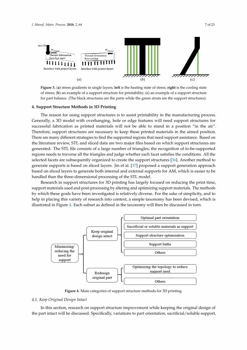
Research in support structures for 3D printing has largely focused on reducing the print time,support materials used and post-processing by altering and optimizing support materials. The methodsby which these goals have been investigated is relatively diverse. For the sake of simplicity, and tohelp in placing this variety of research into context, a simple taxonomy has been devised, which isillustrated in Figure 4. Each subset as defined in the taxonomy will then be discussed in turn.
J. Manuf. Mater. Process. 2018, 2, x FOR PEER REVIEW 7 of 23
4. Support Structure Methods in 3D Printing
The reason for using support structures is to assist printability in the manufacturing process. Generally, a 3D model with overhanging, hole or edge features will need support structures for successful fabrication as printed materials will not be able to stand in a position “in the air”. Therefore, support structures are necessary to keep these printed materials in the aimed position. There are many different strategies to find the supported regions that need support assistance. Based on the literature review, STL and sliced data are two major files based on which support structures are generated. The STL file consists of a large number of triangles; the recognition of to-be-supported regions needs to traverse all the triangles and judge whether each facet satisfies the conditions. All the selected facets are subsequently organized to create the support structures [36]. Another method to generate supports is based on sliced layers. Jin et al. [37] proposed a support generation approach based on sliced layers to generate both internal and external supports for AM, which is easier to be handled than the three-dimensional processing of the STL model.
Research in support structures for 3D printing has largely focused on reducing the print time, support materials used and post-processing by altering and optimizing support materials. The methods by which these goals have been investigated is relatively diverse. For the sake of simplicity, and to help in placing this variety of research into context, a simple taxonomy has been devised, which is illustrated in Figure 4. Each subset as defined in the taxonomy will then be discussed in turn.
Figure 4. Main categories of support structure methods for 3D printing.
4.1. Keep Original Design Intact
In this section, research on support structure improvement while keeping the original design of the part intact will be discussed. Specifically, variations to part orientation, sacrificial/soluble support, support structure optimization and the use of support baths will be discussed with reference to how they influence the support usage and final part quality.
4.1.1. Optimal Part Orientation
The build orientation of an AM part refers to the direction that is orthogonal to the layers of the object being fabricated. AM part orientations play an important role in AM processes as they have a profound influence on the properties of the final part and the nature and amount of support structure needed [38]. In addition, the part orientation affects the support contact area, surface roughness, build time and cost of the fabricated part. Figure 5 illustrates a “T” example. The left needs the most support material (see Figure 5a), followed by the example illustrated in Figure 5b, while Figure 5c does not need any support. However, different support orientations will influence the final printed mechanical properties [39]. Much research has been done on minimizing the support volume by altering the orientation of the supported parts [40–45]. For instance, Zhao [46] proposed a multi-objective function to find an optimal part orientation to minimize volumetric error, build time and
Figure 4. Main categories of support structure methods for 3D printing.
4.1. Keep Original Design Intact
In this section, research on support structure improvement while keeping the original design ofthe part intact will be discussed. Specifically, variations to part orientation, sacrificial/soluble support,
J. Manuf. Mater. Process. 2018, 2, 64 8 of 23
support structure optimization and the use of support baths will be discussed with reference to howthey influence the support usage and final part quality.
4.1.1. Optimal Part Orientation
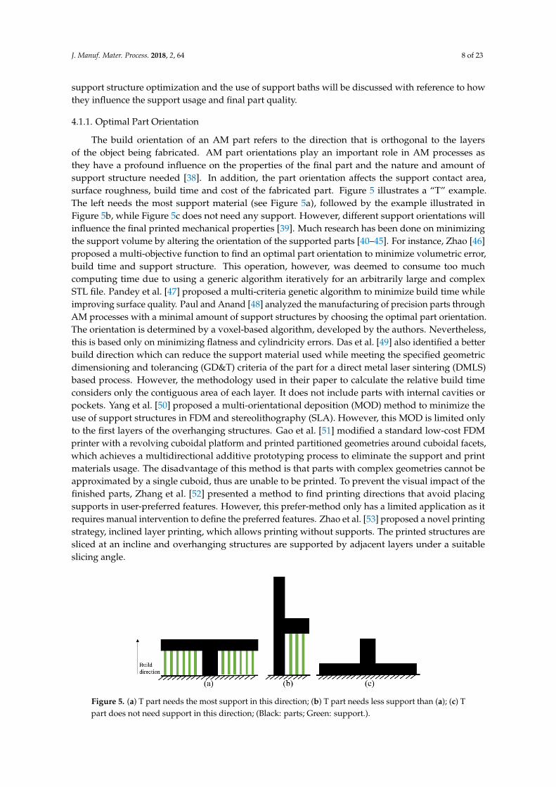
The build orientation of an AM part refers to the direction that is orthogonal to the layersof the object being fabricated. AM part orientations play an important role in AM processes asthey have a profound influence on the properties of the final part and the nature and amount ofsupport structure needed [38]. In addition, the part orientation affects the support contact area,surface roughness, build time and cost of the fabricated part. Figure 5 illustrates a “T” example.The left needs the most support material (see Figure 5a), followed by the example illustrated inFigure 5b, while Figure 5c does not need any support. However, different support orientations willinfluence the final printed mechanical properties [39]. Much research has been done on minimizingthe support volume by altering the orientation of the supported parts [40–45]. For instance, Zhao [46]proposed a multi-objective function to find an optimal part orientation to minimize volumetric error,build time and support structure. This operation, however, was deemed to consume too muchcomputing time due to using a generic algorithm iteratively for an arbitrarily large and complexSTL file. Pandey et al. [47] proposed a multi-criteria genetic algorithm to minimize build time whileimproving surface quality. Paul and Anand [48] analyzed the manufacturing of precision parts throughAM processes with a minimal amount of support structures by choosing the optimal part orientation.The orientation is determined by a voxel-based algorithm, developed by the authors. Nevertheless,this is based only on minimizing flatness and cylindricity errors. Das et al. [49] also identified a betterbuild direction which can reduce the support material used while meeting the specified geometricdimensioning and tolerancing (GD&T) criteria of the part for a direct metal laser sintering (DMLS)based process. However, the methodology used in their paper to calculate the relative build timeconsiders only the contiguous area of each layer. It does not include parts with internal cavities orpockets. Yang et al. [50] proposed a multi-orientational deposition (MOD) method to minimize theuse of support structures in FDM and stereolithography (SLA). However, this MOD is limited onlyto the first layers of the overhanging structures. Gao et al. [51] modified a standard low-cost FDMprinter with a revolving cuboidal platform and printed partitioned geometries around cuboidal facets,which achieves a multidirectional additive prototyping process to eliminate the support and printmaterials usage. The disadvantage of this method is that parts with complex geometries cannot beapproximated by a single cuboid, thus are unable to be printed. To prevent the visual impact of thefinished parts, Zhang et al. [52] presented a method to find printing directions that avoid placingsupports in user-preferred features. However, this prefer-method only has a limited application as itrequires manual intervention to define the preferred features. Zhao et al. [53] proposed a novel printingstrategy, inclined layer printing, which allows printing without supports. The printed structures aresliced at an incline and overhanging structures are supported by adjacent layers under a suitableslicing angle.
J. Manuf. Mater. Process. 2018, 2, x FOR PEER REVIEW 8 of 23
support structure. This operation, however, was deemed to consume too much computing time due to using a generic algorithm iteratively for an arbitrarily large and complex STL file. Pandey et al. [47] proposed a multi-criteria genetic algorithm to minimize build time while improving surface quality. Paul and Anand [48] analyzed the manufacturing of precision parts through AM processes with a minimal amount of support structures by choosing the optimal part orientation. The orientation is determined by a voxel-based algorithm, developed by the authors. Nevertheless, this is based only on minimizing flatness and cylindricity errors. Das et al. [49] also identified a better build direction which can reduce the support material used while meeting the specified geometric dimensioning and tolerancing (GD&T) criteria of the part for a direct metal laser sintering (DMLS) based process. However, the methodology used in their paper to calculate the relative build time considers only the contiguous area of each layer. It does not include parts with internal cavities or pockets. Yang et al. [50] proposed a multi-orientational deposition (MOD) method to minimize the use of support structures in FDM and stereolithography (SLA). However, this MOD is limited only to the first layers of the overhanging structures. Gao et al. [51] modified a standard low-cost FDM printer with a revolving cuboidal platform and printed partitioned geometries around cuboidal facets, which achieves a multidirectional additive prototyping process to eliminate the support and print materials usage. The disadvantage of this method is that parts with complex geometries cannot be approximated by a single cuboid, thus are unable to be printed. To prevent the visual impact of the finished parts, Zhang et al. [52] presented a method to find printing directions that avoid placing supports in user-preferred features. However, this prefer-method only has a limited application as it requires manual intervention to define the preferred features. Zhao et al. [53] proposed a novel printing strategy, inclined layer printing, which allows printing without supports. The printed structures are sliced at an incline and overhanging structures are supported by adjacent layers under a suitable slicing angle.
Figure 5. (a) T part needs the most support in this direction; (b) T part needs less support than (a); (c) T part does not need support in this direction; (Black: parts; Green: support.).
4.1.2. Sacrificial or Soluble Materials as Support
Another method to create support structures is by printing supports with different materials which are soluble or sacrificial in some way. This means when printing a part, the part material is used to print the final part while another sacrificial material (that is either easier to remove or cheaper than the part material) to print the support, thus, reducing the cost and post-processing requirements. In FDM processes, soluble support materials have been used extensively, with preference given to polymer feedstocks that are soluble in relatively benign solvents such as water (poly(vinyl alcohol) and limonene (high impact poly(styrene)). Another common combination is a part printed with acrylonitrile butadiene styrene (ABS) while a sacrificial support structure is printed with polylactic acid (PLA), which is later selectively removed by immersing the 3D printed structure in a solution of isopropyl alcohol and potassium hydroxide to remove the soluble support structures (PLA), while the ABS component will remain intact [54]. Hopkins et al. [55] proposed a support material containing acrylic copolymers with a polymeric impact modifier. The new support material can effectively resist cracking or breaking, and can be removed easily and quickly as well. In an alkaline aqueous solution, the material can be dissolved rapidly. In addition, Ni, Wang and Zhao [56] also
Figure 5. (a) T part needs the most support in this direction; (b) T part needs less support than (a); (c) Tpart does not need support in this direction; (Black: parts; Green: support.).
J. Manuf. Mater. Process. 2018, 2, 64 9 of 23
4.1.2. Sacrificial or Soluble Materials as Support
Another method to create support structures is by printing supports with different materialswhich are soluble or sacrificial in some way. This means when printing a part, the part material isused to print the final part while another sacrificial material (that is either easier to remove or cheaperthan the part material) to print the support, thus, reducing the cost and post-processing requirements.In FDM processes, soluble support materials have been used extensively, with preference given topolymer feedstocks that are soluble in relatively benign solvents such as water (poly(vinyl alcohol))and limonene (high impact poly(styrene)). Another common combination is a part printed withacrylonitrile butadiene styrene (ABS) while a sacrificial support structure is printed with polylacticacid (PLA), which is later selectively removed by immersing the 3D printed structure in a solution ofisopropyl alcohol and potassium hydroxide to remove the soluble support structures (PLA), while theABS component will remain intact [54]. Hopkins et al. [55] proposed a support material containingacrylic copolymers with a polymeric impact modifier. The new support material can effectively resistcracking or breaking, and can be removed easily and quickly as well. In an alkaline aqueous solution,the material can be dissolved rapidly. In addition, Ni, Wang and Zhao [56] also conducted someresearch on poly(vinyl alcohol) (PVA) which can act as a water-soluble support in 3D printing processes.
As for metal processes, Hildreth et al. [57] were the first to try to use sacrificial materials assupports in directed energy deposition. This method can be adopted in other metal deposition systems,such as wire-feed and powder-bed fusion. As a demonstration, a stainless steel bridged structurewith a 90◦ overhang was fabricated using a carbon steel sacrificial support that was later removedthrough electrochemical etching in 41 wt.% nitric acid with bubbling O2. However, all these methodsincrease the post-process treatment and hence labor and cost. Mumtaz et al. [58] adopted an anchorlessselective laser melting (SLM) method to manufacture eutectic alloys parts without support structures.Specifically, they used bismuth and zinc as the basic materials. The shortcoming is that this method islimited to producing eutectic alloys. Recently, Lefky et al. [59], for the first time, brought dissolvablesupports into powder bed based metal printers that are limited to single-material builds.
4.1.3. Support Structure Optimization
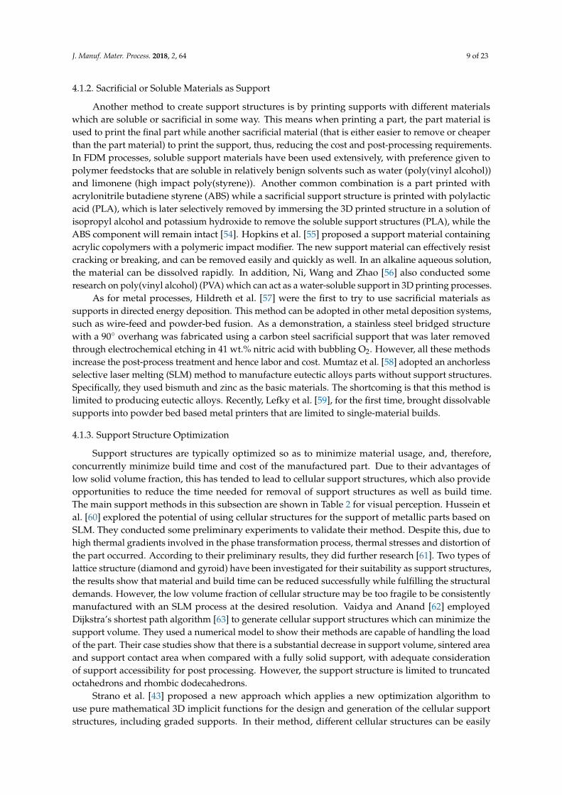
Support structures are typically optimized so as to minimize material usage, and, therefore,concurrently minimize build time and cost of the manufactured part. Due to their advantages oflow solid volume fraction, this has tended to lead to cellular support structures, which also provideopportunities to reduce the time needed for removal of support structures as well as build time.The main support methods in this subsection are shown in Table 2 for visual perception. Hussein etal. [60] explored the potential of using cellular structures for the support of metallic parts based onSLM. They conducted some preliminary experiments to validate their method. Despite this, due tohigh thermal gradients involved in the phase transformation process, thermal stresses and distortion ofthe part occurred. According to their preliminary results, they did further research [61]. Two types oflattice structure (diamond and gyroid) have been investigated for their suitability as support structures,the results show that material and build time can be reduced successfully while fulfilling the structuraldemands. However, the low volume fraction of cellular structure may be too fragile to be consistentlymanufactured with an SLM process at the desired resolution. Vaidya and Anand [62] employedDijkstra’s shortest path algorithm [63] to generate cellular support structures which can minimize thesupport volume. They used a numerical model to show their methods are capable of handling the loadof the part. Their case studies show that there is a substantial decrease in support volume, sintered areaand support contact area when compared with a fully solid support, with adequate considerationof support accessibility for post processing. However, the support structure is limited to truncatedoctahedrons and rhombic dodecahedrons.
Strano et al. [43] proposed a new approach which applies a new optimization algorithm touse pure mathematical 3D implicit functions for the design and generation of the cellular supportstructures, including graded supports. In their method, different cellular structures can be easily

J. Manuf. Mater. Process. 2018, 2, 64 10 of 23
defined and optimized, especially graded structures providing less support where it is not neededand more robust support elsewhere. Lu et al. [64] utilized the Voronoi diagram to compute irregularhoneycomb-like volume tessellations which define the inner structure. They took honeycomb-cellstructure as inner support structures based on a hollowing optimization algorithm. However, they onlyconsidered the inner support as a part of the final product rather than as a removable support structure.Wei et al. [65] presented a sparse tree support structure generation algorithm. This method consumesless time and materials and is more stable for FDM. It may be further improved if surface quality canbe considered in the future. Vanek et al. [66] proposed a tree-like support structure generation methodfor FDM which can reduce printing time and material used. However, their method is geometry-basedand considers only the angle and length of the supporting strut.
Schmidt et al. [67] proposed a type of space-efficient branching support structure which canreduce wasted time and material in fused-filament 3D printing (FDM). In their study, 75% less plasticsupport material was used than the manufacturer-provided supports, as well as reducing print timeby an hour. Shen [68] proposed a bridge support structure generation algorithm which can save anaverage of about 15.19% of printing and about 24.41% of the time, compared with a vertical supportstructure. They also developed an automatic generation algorithm based on critical angle constraint,which can achieve the same goals [69].
Gan et al. [70] explored “Y”, “IY” and Pin support structures to help design practicalsupports for thin plates and cuboids, based on SLM. Their results revealed that, with only 2.2%overhang–support contact area, uniformly spaced vertical struts can manufacture relatively levelthin plates. Another conclusion is that unequally spaced support structures can transform theheat dissipation pattern in the thin plate, thus, resulting in thermal distortions. Regardless of this,further experiments are necessary for adapting the method to more applications. Zhao et al. [71]employed particle swarm optimization (PSO) algorithm with a novel constraint handling strategy tominimize the material waste and contacting area with the consideration of mechanical analysis on thesupport structures. However, they only considered the base supports in their work, though theoreticallyit could be extended to the in-part support structures. In addition, only simulation work has been donein this paper, physical experiments are still necessary. Dumas et al. [72] presented a novel way to selectpoints to be supported based not only on overhangs but also on the stability of the printed modelthroughout the entire build process. An efficient algorithm was shown to build bridge scaffoldings thatsupport given sets of points in space with less material. However, their method does not consider therobustness of the printed object and the sweeping algorithm is unaware of the geometry of the objectaside from the collision detection. Recently, Habib and Khoda [73] proposed a grain architecture designas a support considering the amount of support volume, maximum contact interface, lower fabricationtime and ease of fabrication.
Table 2. Demonstration of main support methods.
Support Methods Suitable Techniques Examples
Lattice support [61] Metal AM processes
J. Manuf. Mater. Process. 2018, 2, x FOR PEER REVIEW 10 of 23
structure. They also developed an automatic generation algorithm based on critical angle constraint, which can achieve the same goals [69].
Gan et al. [70] explored “Y”, “IY” and Pin support structures to help design practical supports for thin plates and cuboids, based on SLM. Their results revealed that, with only 2.2% overhang–support contact area, uniformly spaced vertical struts can manufacture relatively level thin plates. Another conclusion is that unequally spaced support structures can transform the heat dissipation pattern in the thin plate, thus, resulting in thermal distortions. Regardless of this, further experiments are necessary for adapting the method to more applications. Zhao et al. [71] employed particle swarm optimization (PSO) algorithm with a novel constraint handling strategy to minimize the material waste and contacting area with the consideration of mechanical analysis on the support structures. However, they only considered the base supports in their work, though theoretically it could be extended to the in-part support structures. In addition, only simulation work has been done in this paper, physical experiments are still necessary. Dumas et al. [72] presented a novel way to select points to be supported based not only on overhangs but also on the stability of the printed model throughout the entire build process. An efficient algorithm was shown to build bridge scaffoldings that support given sets of points in space with less material. However, their method does not consider the robustness of the printed object and the sweeping algorithm is unaware of the geometry of the object aside from the collision detection. Recently, Habib and Khoda [73] proposed a grain architecture design as a support considering the amount of support volume, maximum contact interface, lower fabrication time and ease of fabrication.
Table 2. Demonstration of main support methods.
Support Methods Suitable Techniques Examples
Lattice support [61] Metal AM processes
Unit cell support [62] All processes
Cellular support [43] SLM
J. Manuf. Mater. Process. 2018, 2, 64 11 of 23
Table 2. Cont.
Support Methods Suitable Techniques Examples
Unit cell support[62] All processes
J. Manuf. Mater. Process. 2018, 2, x FOR PEER REVIEW 10 of 23
structure. They also developed an automatic generation algorithm based on critical angle constraint, which can achieve the same goals [69].
Gan et al. [70] explored “Y”, “IY” and Pin support structures to help design practical supports for thin plates and cuboids, based on SLM. Their results revealed that, with only 2.2% overhang–support contact area, uniformly spaced vertical struts can manufacture relatively level thin plates. Another conclusion is that unequally spaced support structures can transform the heat dissipation pattern in the thin plate, thus, resulting in thermal distortions. Regardless of this, further experiments are necessary for adapting the method to more applications. Zhao et al. [71] employed particle swarm optimization (PSO) algorithm with a novel constraint handling strategy to minimize the material waste and contacting area with the consideration of mechanical analysis on the support structures. However, they only considered the base supports in their work, though theoretically it could be extended to the in-part support structures. In addition, only simulation work has been done in this paper, physical experiments are still necessary. Dumas et al. [72] presented a novel way to select points to be supported based not only on overhangs but also on the stability of the printed model throughout the entire build process. An efficient algorithm was shown to build bridge scaffoldings that support given sets of points in space with less material. However, their method does not consider the robustness of the printed object and the sweeping algorithm is unaware of the geometry of the object aside from the collision detection. Recently, Habib and Khoda [73] proposed a grain architecture design as a support considering the amount of support volume, maximum contact interface, lower fabrication time and ease of fabrication.
Table 2. Demonstration of main support methods.
Support Methods Suitable Techniques Examples
Lattice support [61] Metal AM processes
Unit cell support [62] All processes
Cellular support [43] SLM
Cellular support[43] SLM
J. Manuf. Mater. Process. 2018, 2, x FOR PEER REVIEW 10 of 23
structure. They also developed an automatic generation algorithm based on critical angle constraint, which can achieve the same goals [69].
Gan et al. [70] explored “Y”, “IY” and Pin support structures to help design practical supports for thin plates and cuboids, based on SLM. Their results revealed that, with only 2.2% overhang–support contact area, uniformly spaced vertical struts can manufacture relatively level thin plates. Another conclusion is that unequally spaced support structures can transform the heat dissipation pattern in the thin plate, thus, resulting in thermal distortions. Regardless of this, further experiments are necessary for adapting the method to more applications. Zhao et al. [71] employed particle swarm optimization (PSO) algorithm with a novel constraint handling strategy to minimize the material waste and contacting area with the consideration of mechanical analysis on the support structures. However, they only considered the base supports in their work, though theoretically it could be extended to the in-part support structures. In addition, only simulation work has been done in this paper, physical experiments are still necessary. Dumas et al. [72] presented a novel way to select points to be supported based not only on overhangs but also on the stability of the printed model throughout the entire build process. An efficient algorithm was shown to build bridge scaffoldings that support given sets of points in space with less material. However, their method does not consider the robustness of the printed object and the sweeping algorithm is unaware of the geometry of the object aside from the collision detection. Recently, Habib and Khoda [73] proposed a grain architecture design as a support considering the amount of support volume, maximum contact interface, lower fabrication time and ease of fabrication.
Table 2. Demonstration of main support methods.
Support Methods Suitable Techniques Examples
Lattice support [61] Metal AM processes
Unit cell support [62] All processes
Cellular support [43] SLM
Honeycombsupport [64] FDM
J. Manuf. Mater. Process. 2018, 2, x FOR PEER REVIEW 11 of 23
Honeycomb support [64] FDM
Sparse tree support [65] FDM/DLP
Tree-like support [66] FDM
Space-efficient branching support [67] FDM
Bridge support [68] FDM
“Y”, “IY” and Pin support [70] SLM
Grain support [73] FDM
4.1.4. Support Baths
While ubiquitous in top-down stereolithography, support baths have recently garnered interest in other areas of 3D printing, mainly in the area of bio-fabrication. During the printing processes, the
Sparse tree support[65] FDM/DLP
J. Manuf. Mater. Process. 2018, 2, x FOR PEER REVIEW 11 of 23
Honeycomb support [64] FDM
Sparse tree support [65] FDM/DLP
Tree-like support [66] FDM
Space-efficient branching support [67] FDM
Bridge support [68] FDM
“Y”, “IY” and Pin support [70] SLM
Grain support [73] FDM
4.1.4. Support Baths
While ubiquitous in top-down stereolithography, support baths have recently garnered interest in other areas of 3D printing, mainly in the area of bio-fabrication. During the printing processes, the
Tree-like support[66] FDM
J. Manuf. Mater. Process. 2018, 2, x FOR PEER REVIEW 11 of 23
Honeycomb support [64] FDM
Sparse tree support [65] FDM/DLP
Tree-like support [66] FDM
Space-efficient branching support [67] FDM
Bridge support [68] FDM
“Y”, “IY” and Pin support [70] SLM
Grain support [73] FDM
4.1.4. Support Baths
While ubiquitous in top-down stereolithography, support baths have recently garnered interest in other areas of 3D printing, mainly in the area of bio-fabrication. During the printing processes, the
Space-efficientbranching support
[67]FDM
J. Manuf. Mater. Process. 2018, 2, x FOR PEER REVIEW 11 of 23
Honeycomb support [64] FDM
Sparse tree support [65] FDM/DLP
Tree-like support [66] FDM
Space-efficient branching support [67] FDM
Bridge support [68] FDM
“Y”, “IY” and Pin support [70] SLM
Grain support [73] FDM
4.1.4. Support Baths
While ubiquitous in top-down stereolithography, support baths have recently garnered interest in other areas of 3D printing, mainly in the area of bio-fabrication. During the printing processes, the
Bridge support [68] FDM
J. Manuf. Mater. Process. 2018, 2, x FOR PEER REVIEW 11 of 23
Honeycomb support [64] FDM
Sparse tree support [65] FDM/DLP
Tree-like support [66] FDM
Space-efficient branching support [67] FDM
Bridge support [68] FDM
“Y”, “IY” and Pin support [70] SLM
Grain support [73] FDM
4.1.4. Support Baths
While ubiquitous in top-down stereolithography, support baths have recently garnered interest in other areas of 3D printing, mainly in the area of bio-fabrication. During the printing processes, the

J. Manuf. Mater. Process. 2018, 2, 64 12 of 23
Table 2. Cont.
Support Methods Suitable Techniques Examples
“Y”, “IY” and Pinsupport [70] SLM
J. Manuf. Mater. Process. 2018, 2, x FOR PEER REVIEW 11 of 23
Honeycomb support [64] FDM
Sparse tree support [65] FDM/DLP
Tree-like support [66] FDM
Space-efficient branching support [67] FDM
Bridge support [68] FDM
“Y”, “IY” and Pin support [70] SLM
Grain support [73] FDM
4.1.4. Support Baths
While ubiquitous in top-down stereolithography, support baths have recently garnered interest in other areas of 3D printing, mainly in the area of bio-fabrication. During the printing processes, the
Grain support [73] FDM
J. Manuf. Mater. Process. 2018, 2, x FOR PEER REVIEW 11 of 23
Honeycomb support [64] FDM
Sparse tree support [65] FDM/DLP
Tree-like support [66] FDM
Space-efficient branching support [67] FDM
Bridge support [68] FDM
“Y”, “IY” and Pin support [70] SLM
Grain support [73] FDM
4.1.4. Support Baths
While ubiquitous in top-down stereolithography, support baths have recently garnered interest in other areas of 3D printing, mainly in the area of bio-fabrication. During the printing processes, the
4.1.4. Support Baths
While ubiquitous in top-down stereolithography, support baths have recently garnered interestin other areas of 3D printing, mainly in the area of bio-fabrication. During the printing processes,the printed parts are stabilized by the support bath that readily flows when applying an externalforce larger than its yield stress, such as that induced by a moving extrusion nozzle. Once the nozzlemoves on, the fluidized support material fills any crevasses in its wake and then returns to its gel-likebehavior. This bulk support material could successfully support every feature of a printed part whenthe yield stress of the support material is higher than surface tension and gravitational forces. Then, thewhole liquid structure is solidified in situ by applying suitable cross-linking mechanisms [74,75].Hinton et al. [76] demonstrated a new method of 3D printing polydimethylsiloxane (PDMS) usinga hydrophilic Carbopol support bath. Carbopol support acts as a Bingham plastic that yields andfluidizes when the syringe tip of the 3D printer moves through it, but acts as a solid for the PDMSextruded within it. Suspension 3D printing was proposed by Yu et al. [77] which used self-healinghydrogel support to create macroscopic structures of liquid metal that exhibits properties indicative ofa non-printable object. Another advantage of support baths is that they are theoretically reusable andcan be seen as a sustainable and green support method.
4.1.5. Others
In addition to the mentioned methods for improving support structures, there are a variety ofother trials. Chalasani et al. [78] proposed a computational algorithm for support minimization forFDM using a ray casting approach. Huang et al. [79] designed and tested a novel support structurewith sloping walls for FDM, through an algorithm, based on the STL model. The results showthat this support structure can greatly reduce the volume of support (30%), thus optimizing thefabrication process. But, they did not consider the reduction of total support contact area with the
J. Manuf. Mater. Process. 2018, 2, 64 13 of 23
part. Calignano [80] optimized the design of supports for overhanging structures in aluminum andtitanium alloys by SLM. He used Taguchi methods to find values that allow obtaining the conditionmost suitable for easy removal and reducing deformations for most geometries of the printed parts.Barnett and Gosselin [81] introduced new support geometry algorithms based on the use of twosupport materials, one of which is weak and easily removed and another that can maintain structuralintegrity. In addition, the effects of the process parameters on the lowest printable overhang angle sizewere studied by the authors for minimizing support waste [82].
The use of skin-frame structures was investigated by Wang et al. [83] with an algorithm derived forthe purpose of reducing the material cost in printing a given 3D object, with the frame effectively actingas a support structure. Unfortunately, the alteration to mechanical properties had not been considered.Zhang et al. [84] presented a novel method for designing the internal supporting structures of 3Dobjects based on their medial axis in order to reduce the amount of material used, with satisfactoryquality. However, all the above methods do not consider a self-printability requirement (i.e., thesupport structure itself should not require a support structure). Lee and Lee [85] proposed a newinner support structure generation algorithm which can reduce the amount of material used to fillthe interior of an object and the manufacturing time as well, while ensuring self-printability. Jin etal. [37] presented an approach to generate both external and internal support structures for AM basedon sliced layers to enhance the manufacturing accuracy and efficiency. Their experiments validatedthat this can reduce fabricating material usage and build time. However, they failed to take account ofpost-process impact to the surface quality and the removability of the support structures, especiallyinternal support.
4.2. Redesign Original Part
In this section, research on support structure improvement by redesigning/changing the geometryof the original part is discussed. Generally, redesign is based on topology optimization (TO) orfeature-based methods and the final part can still keep the function of that original part.
4.2.1. Optimizing the Topology to Reduce Support Used
Usually, TO methods are used to tackle practical design problems with traditional manufacturingprocesses, such as machining and casting. However, as the development of 3D printing technologyproceeds apace, it is desirable to adopt TO in 3D printing. TO can provide the ‘best’ design (structure)in a given area, load and constraint condition. The general workflow of TO for 3D printing can be foundin the following review [86]. Many researchers have done relevant works [87–92]. Unfortunately, to thebest of the authors’ knowledge, only seven papers are related to the reduction of the support structure.
Gaynor and Guest [93] attempted to more thoroughly integrate overhang constraints into thetopology optimization methodology. They embed a projection step associated with the overhangangle constraint within the standard Heaviside Projection methodology (HPM) [94]. By designingcomponents and structures whose features rise in the build direction at an angle that is greater thana process specific minimum allowable self-supporting angle, anchors in metallic AM processes orpolymer support materials can be eliminated. Mirzendehdel and Suresh [95] proposed a topologyoptimization methodology that can lead to designs requiring significantly reduced support structures.Cloots et al. [96] developed a specific component segmentation strategy for SLM which allows thesegmentation of critical areas of the parts by applying a specific scanning strategy with appropriateenergy input, thus reducing the support structures needed. Leary et al. [97] proposed an automatedmethod to modify topologically optimal geometries as required to enable support-free manufacture.However, this method has been applied to only polymeric additive systems. Langelaar [98] proposeda topology optimization formulation that can exclude unprintable geometries from the design space,resulting in fully self-supporting optimized designs. However, this will be detrimental to theperformance of some products in some cases and can only be used in limited components.

J. Manuf. Mater. Process. 2018, 2, 64 14 of 23
As stated above, all six of these papers are about topologically optimizing the final product toreduce the support needed, rather than the support structure itself. Strictly speaking, these studiescould not be directly seen as support structure research as TO is not applied in support structures.This distinction is of particular relevance as AM processes move towards mainstream manufacturing,where further constraints on design will limit the ability to redesign a component based on printabilityand support structures. Recently, Kuo et al. [99] tried to integrate topology optimization directly intothe support structure generation process itself, though they only considered a fixed part orientation.Further work needs to be carried out in the future to fully apply TO in support generation.
4.2.2. Others
Hu et al. [100] proposed an orientation-driven shape optimizer to reduce the supporting structuresused in single material-based AM (in particular FDM and selective laser sintering (SLS)). Their methodcan meet the overhang angle constraint through modifying a given topology by changing the anglesand shapes of features, thus, reducing supports. Unfortunately, this method, to some extent, needs tochange the shape of products, which is unacceptable in some cases. Figure 6 shows some printedexamples by changing the original shapes for reducing support waste.
J. Manuf. Mater. Process. 2018, 2, x FOR PEER REVIEW 13 of 23
proceeds apace, it is desirable to adopt TO in 3D printing. TO can provide the ‘best’ design (structure) in a given area, load and constraint condition. The general workflow of TO for 3D printing can be found in the following review [86]. Many researchers have done relevant works [87–92]. Unfortunately, to the best of the authors’ knowledge, only seven papers are related to the reduction of the support structure.
Gaynor and Guest [93] attempted to more thoroughly integrate overhang constraints into the topology optimization methodology. They embed a projection step associated with the overhang angle constraint within the standard Heaviside Projection methodology (HPM) [94]. By designing components and structures whose features rise in the build direction at an angle that is greater than a process specific minimum allowable self-supporting angle, anchors in metallic AM processes or polymer support materials can be eliminated. Mirzendehdel and Suresh [95] proposed a topology optimization methodology that can lead to designs requiring significantly reduced support structures. Cloots et al. [96] developed a specific component segmentation strategy for SLM which allows the segmentation of critical areas of the parts by applying a specific scanning strategy with appropriate energy input, thus reducing the support structures needed. Leary et al. [97] proposed an automated method to modify topologically optimal geometries as required to enable support-free manufacture. However, this method has been applied to only polymeric additive systems. Langelaar [98] proposed a topology optimization formulation that can exclude unprintable geometries from the design space, resulting in fully self-supporting optimized designs. However, this will be detrimental to the performance of some products in some cases and can only be used in limited components.
As stated above, all six of these papers are about topologically optimizing the final product to reduce the support needed, rather than the support structure itself. Strictly speaking, these studies could not be directly seen as support structure research as TO is not applied in support structures. This distinction is of particular relevance as AM processes move towards mainstream manufacturing, where further constraints on design will limit the ability to redesign a component based on printability and support structures. Recently, Kuo et al. [99] tried to integrate topology optimization directly into the support structure generation process itself, though they only considered a fixed part orientation. Further work needs to be carried out in the future to fully apply TO in support generation.
4.2.2. Others
Hu et al. [100] proposed an orientation-driven shape optimizer to reduce the supporting structures used in single material-based AM (in particular FDM and selective laser sintering (SLS)). Their method can meet the overhang angle constraint through modifying a given topology by changing the angles and shapes of features, thus, reducing supports. Unfortunately, this method, to some extent, needs to change the shape of products, which is unacceptable in some cases. Figure 6 shows some printed examples by changing the original shapes for reducing support waste.
Figure 6. Examples for reducing support waste by deforming original shape [100].
5. Discussion and Future Directions
Of the research looking into methods of improving support material utilization, the majority concern FDM printing technology (27 publications), and just a few could be suitable for all AM techniques (5 publications). The reason for this is most probably because of the unavoidable and higher requirement of support in FDM, and the popularity of the printing technique. FDM needs material beneath the printed layer as it is extrusion-based, while for powder processes, the powder could take the role of support. In addition, the unused powder which acts as the support can be
Figure 6. Examples for reducing support waste by deforming original shape [100].
5. Discussion and Future Directions
Of the research looking into methods of improving support material utilization, the majorityconcern FDM printing technology (27 publications), and just a few could be suitable for all AMtechniques (5 publications). The reason for this is most probably because of the unavoidable and higherrequirement of support in FDM, and the popularity of the printing technique. FDM needs materialbeneath the printed layer as it is extrusion-based, while for powder processes, the powder could takethe role of support. In addition, the unused powder which acts as the support can be reused, to anextent, in the future. However, the supports fabricated in extrusion-based processes are generallyunable to be reused, unless the supports are re-manufactured into filaments. For powder bed processes,the support material is generally for ameliorating against thermal stresses during manufacture and toanchor the printed part within the build volume.
Compared with FDM, the number of papers published on metal additive processes regardingsupport is quite small (8 publications). The comparatively low accessibility to metal 3D printersis probably one of the causes of this discrepancy. However, this does not necessarily meansupport structure for metal processes is not a topic of significant importance. On the contrary,metal-based processes will have greater research focus as their significance increases as usage ofadditive technologies trends from prototyping to manufacturing. In contrast, polymer-based additivemanufacturing technologies are easy to access and cheap, like FDM. It would, therefore, be desirable ifresearch into the more accessible additive manufacturing technologies could be more widely related toother techniques. The following discussion will focus on the current limitations of existing supportgeneration strategies and on ways in which the research can be applied in a more universal manner.
5.1. Limitations of Current Methods
A significant amount of research has been done on improving support for additive manufacturingand this has achieved a lot in reducing support material and time used. There are, however, still many

J. Manuf. Mater. Process. 2018, 2, 64 15 of 23
limitations in the current improved methods. For instance, the method from Hu et al. [100], to someextent, needs to change the shape of products for self-support, which will lead to inevitable alterationscompared with the original 3D model. This is unacceptable if the tolerance is small, especially for afunctional component which needs exactly the size and characteristics initially specified. For example,when a part from an engine is broken and will be replaced by 3D printing that part is supposed tohave the exact size and features to fit the engine. Therefore, altering the 3D model, even just a little bit,may not be acceptable.
For optimal part orientation, it is true that support could be reduced significantly by changing theprint orientation [41–43,45]. However, the strength of the printed part may be changed accordinglyas well, due to the anisotropic mechanical properties typically found in additive manufacturingtechnology. For example, the strengths of a dog bone as shown in Figure 7 printed in X (a) and Y (b)directions will be different [101]. From a design perspective, it is, therefore, desirable to manufacture apart so that the principal stresses align with the strongest print direction. Research to date has focusedsolely on the reduction in support material irrespective of mechanical properties. As the use of additivetechnologies for final part manufacture increases, the balance of time and cost savings in manufacturedue to support materials will have to be balanced with the influence on mechanical properties.
J. Manuf. Mater. Process. 2018, 2, x FOR PEER REVIEW 14 of 23
reused, to an extent, in the future. However, the supports fabricated in extrusion-based processes are generally unable to be reused, unless the supports are re-manufactured into filaments. For powder bed processes, the support material is generally for ameliorating against thermal stresses during manufacture and to anchor the printed part within the build volume.
Compared with FDM, the number of papers published on metal additive processes regarding support is quite small (8 publications). The comparatively low accessibility to metal 3D printers is probably one of the causes of this discrepancy. However, this does not necessarily mean support structure for metal processes is not a topic of significant importance. On the contrary, metal-based processes will have greater research focus as their significance increases as usage of additive technologies trends from prototyping to manufacturing. In contrast, polymer-based additive manufacturing technologies are easy to access and cheap, like FDM. It would, therefore, be desirable if research into the more accessible additive manufacturing technologies could be more widely related to other techniques. The following discussion will focus on the current limitations of existing support generation strategies and on ways in which the research can be applied in a more universal manner.
5.1. Limitations of Current Methods
A significant amount of research has been done on improving support for additive manufacturing and this has achieved a lot in reducing support material and time used. There are, however, still many limitations in the current improved methods. For instance, the method from Hu et al. [100], to some extent, needs to change the shape of products for self-support, which will lead to inevitable alterations compared with the original 3D model. This is unacceptable if the tolerance is small, especially for a functional component which needs exactly the size and characteristics initially specified. For example, when a part from an engine is broken and will be replaced by 3D printing that part is supposed to have the exact size and features to fit the engine. Therefore, altering the 3D model, even just a little bit, may not be acceptable.
For optimal part orientation, it is true that support could be reduced significantly by changing the print orientation [41–43,45]. However, the strength of the printed part may be changed accordingly as well, due to the anisotropic mechanical properties typically found in additive manufacturing technology. For example, the strengths of a dog bone as shown in Figure 7 printed in X (a) and Y (b) directions will be different [101]. From a design perspective, it is, therefore, desirable to manufacture a part so that the principal stresses align with the strongest print direction. Research to date has focused solely on the reduction in support material irrespective of mechanical properties. As the use of additive technologies for final part manufacture increases, the balance of time and cost savings in manufacture due to support materials will have to be balanced with the influence on mechanical properties.
Figure 7. Illustration of dog bone printed in (a) X direction and (b) Y direction.
The use of a material different from that used in building the object, such as the use of soluble support materials, presents inherent advantages with regards to the automation of post-processing. It does, however, raise further complications in the printing process as the AM technique has to be amenable to the use of multiple materials. It is, therefore, most suitable for techniques where this is relatively trivial, which is predominantly the case with deposition-based processes such as material jetting and fused deposition modeling. Serendipitously, these are perhaps the AM techniques in which soluble support materials are most desired. In addition, consideration has to be given to the removal
Figure 7. Illustration of dog bone printed in (a) X direction and (b) Y direction.
The use of a material different from that used in building the object, such as the use of solublesupport materials, presents inherent advantages with regards to the automation of post-processing.It does, however, raise further complications in the printing process as the AM technique has to beamenable to the use of multiple materials. It is, therefore, most suitable for techniques where this isrelatively trivial, which is predominantly the case with deposition-based processes such as materialjetting and fused deposition modeling. Serendipitously, these are perhaps the AM techniques in whichsoluble support materials are most desired. In addition, consideration has to be given to the removalprocess, which will take additional time in manufacturing and may involve the use of potentiallyharmful solvents. Approaches that limit the use of soluble material to only where it is needed may beof increased interest [81]. The use of support baths that provide the role of support material withoutthe necessity of directly printing a support is also of considerable interest for similar reasons.
For seeking better structures as supports, some structures have been optimized to fulfill theirprimary support role in the most energy and material efficient way possible. Unfortunately, the newsupport structure might also bring new problems during 3D printing. For instance, Hussein et al. [60]explored the potential of using cellular structures as support of metallic parts based on SLM. However,due to high thermal gradients involved in the phase transformation process, thermal stresses anddistortion of the part occur.
5.2. Efforts in Eliminating Supports
In addition to optimizing support structures in previous studies, some researchers have alsocarried out some work on eliminating support usage. Zhao et al. [53] tried to use an inclined depositionmethod for building parts in fused deposition modeling processes which can change the directionof the nozzle for eliminating support consumption. However, this method can only be used infused deposition modeling processes and may require accurate control of the nozzle as well as pathcalculation. Removable water/ice support for stereolithography was tried and proposed by Jin and
J. Manuf. Mater. Process. 2018, 2, 64 16 of 23
Chen [102]. Though this strategy seems to eliminate using the part material as support, it insteadrequires the repeated heating and cooling of water to induce the necessary phase change, which maybe less energy efficient. Multi-axis or robotic additive manufacturing processes were also investigatedby [103–105]. However, these techniques may require high cost at the beginning and the extracomplexity within the manufacturing process will likely render any support reduction strategieshighly specific to the process in question. The main purposes of multi-axis additive manufacturing arefor special functions such as repairing components.
5.3. Principles of Support Design
In general, a large proportion of support methods in the literature are based on the followingrules: (1) avoid large-size holes parallel to the printing surface; (2) avoid surfaces with a large overhangangle; (3) avoid trapped surfaces where support materials would be difficult or impossible to remove;and (4) structure optimization to reduce the support material used. While these methods are ofsignificant validity, especially when focusing on prototyping applications, the freedom to produce anobject based around these principles may be limited when manufacturing parts for real-world usedue to the constraints placed upon final part geometry and performance. It is, therefore, apposite toestablish whether the methods discussed in the literature are able to work within a relevant set ofconstraints related to the defined application of the part. Support structure design should also considerthe printability, constraint of overhang angle size, part balance, thermal conditions, ease of removaland any other relevant factors. Generally, the design of support structures should be based on thefollowing principles:
• The support should be able to prevent parts from collapse/warping, especially the outer contourarea which needs support; for metal processes, stress and strain needs to be considered andthermal simulation modeling can be conducted for design;
• The connection between the support and final parts should be of minimal strength to perform thesupport function, with the aim of easily removing support;
• The contact area between the support and final parts should be as small as possible to reducesurface deterioration after support removal;
• When designing the support, material consumption and build time should be considered as asignificant factor, as well as the trade-off between them and the final printed quality.
There are many software applications for generating support structures. For example, CURA andSlic3r for FDM processes and Magic for metallic processes. However, there is still no knowledge forwhich software is better than the other in terms of support structures.
5.4. Support Structure Modeling
The majority of works carried out on support modeling are for reducing support structure usage,irrespective of changing printing orientation or adopting new structures. There are papers publishedon modeling and predicting the thermal behavior change of the material during 3D printing processes,which can help understand, optimize and control the deposition process [106–110]. However, littleresearch has been carried out to investigate support structure modeling for optimizing heat dissipationand residual stresses for improving the support structure, thus, enhancing the final part quality.Research on support structure modeling is quite necessary, especially for metal 3D printing processes.Metal-based processes typically aim to produce industrially relevant components which need to beprecise within tolerance and should be strong enough for functionality. Support structure plays acrucial role in metal additive manufacturing by eliminating cracks, curling up, sag or shrinkage.If thermal and support force generation process modeling could be conducted, the modeling resultswill be beneficial for understanding and further improving the support structure for AM, especiallyfor industrial development.

J. Manuf. Mater. Process. 2018, 2, 64 17 of 23
5.5. Integrating Topology Optimization into Support Structure
Topology optimization has been used in structure optimization for a long time, which is amathematical method that can reduce material used and optimizes material layout within a givendesign space, for a given set of loads, boundary conditions and constraints with the goal of maximizingthe performance of the system. Given this advantage, it is beneficial to integrate TO into supportstructures for 3D printing. Although much research has been done on topologically optimizing3D structures for AM, most of them are on designing the final parts. Among them, six papersare related to reducing the support needed through topologically optimizing the final part ratherthan support structure themselves. Although optimizing topology is mainly for better functionalperformance in the use stage, it is potentially still useful and effective when optimizing support forlarge-scale parts. Hence, research on integrating TO for the support structure is still necessary as TOcan significantly reduce the support needed and optimize the support structures based on materialproperties. The workflow of TO for support structure should be in the way shown in Figure 8. Due tothe limitation of 3D printers’ resolution and the nature of the layer-by-layer process, some over-thinstruts or struts with too large angles could not be printed successfully. For example, it is impossibleto print a support with 0.1 mm diameter size according to the TO result when the print nozzlehas a diameter of 0.2 mm. It is also unavailable if a support structure after topology optimizationstill needs another support beneath it. Therefore, some criteria and uniformed tolerance of supportstructure for a given AM technique should be made in order to 3D print parts reliably using thesesupports. Specifically, some certain conditions (such as printable angle size and nozzle size) should beconstrained in topology optimization settings in the future.
J. Manuf. Mater. Process. 2018, 2, x FOR PEER REVIEW 16 of 23
5.4. Support Structure Modeling
The majority of works carried out on support modeling are for reducing support structure usage, irrespective of changing printing orientation or adopting new structures. There are papers published on modeling and predicting the thermal behavior change of the material during 3D printing processes, which can help understand, optimize and control the deposition process [106–110]. However, little research has been carried out to investigate support structure modeling for optimizing heat dissipation and residual stresses for improving the support structure, thus, enhancing the final part quality. Research on support structure modeling is quite necessary, especially for metal 3D printing processes. Metal-based processes typically aim to produce industrially relevant components which need to be precise within tolerance and should be strong enough for functionality. Support structure plays a crucial role in metal additive manufacturing by eliminating cracks, curling up, sag or shrinkage. If thermal and support force generation process modeling could be conducted, the modeling results will be beneficial for understanding and further improving the support structure for AM, especially for industrial development.
5.5. Integrating Topology Optimization into Support Structure
Topology optimization has been used in structure optimization for a long time, which is a mathematical method that can reduce material used and optimizes material layout within a given design space, for a given set of loads, boundary conditions and constraints with the goal of maximizing the performance of the system. Given this advantage, it is beneficial to integrate TO into support structures for 3D printing. Although much research has been done on topologically optimizing 3D structures for AM, most of them are on designing the final parts. Among them, six papers are related to reducing the support needed through topologically optimizing the final part rather than support structure themselves. Although optimizing topology is mainly for better functional performance in the use stage, it is potentially still useful and effective when optimizing support for large-scale parts. Hence, research on integrating TO for the support structure is still necessary as TO can significantly reduce the support needed and optimize the support structures based on material properties. The workflow of TO for support structure should be in the way shown in Figure 8. Due to the limitation of 3D printers’ resolution and the nature of the layer-by-layer process, some over-thin struts or struts with too large angles could not be printed successfully. For example, it is impossible to print a support with 0.1 mm diameter size according to the TO result when the print nozzle has a diameter of 0.2 mm. It is also unavailable if a support structure after topology optimization still needs another support beneath it. Therefore, some criteria and uniformed tolerance of support structure for a given AM technique should be made in order to 3D print parts reliably using these supports. Specifically, some certain conditions (such as printable angle size and nozzle size) should be constrained in topology optimization settings in the future.
Figure 8. Workflow of topology optimization for support structures.
5.6. Standardized Model for Support Structure Comparison in Different Processes
The experimental evaluation of the efficiency of support material usage has so far relied on the comparison between the ‘standard’ support generation settings for a particular 3D printing technique and the new method of support generation. This has typically taken the form of looking at the savings in terms of time and amount of material used. Such an approach, unfortunately, makes it difficult to compare different support generation techniques to each other due to the lack of standardization in both the model that is used to test the efficacy of the support generation and the method of quantification. Within the published literature, each support method has not provided the explicit
Figure 8. Workflow of topology optimization for support structures.
5.6. Standardized Model for Support Structure Comparison in Different Processes
The experimental evaluation of the efficiency of support material usage has so far relied on thecomparison between the ‘standard’ support generation settings for a particular 3D printing techniqueand the new method of support generation. This has typically taken the form of looking at the savingsin terms of time and amount of material used. Such an approach, unfortunately, makes it difficult tocompare different support generation techniques to each other due to the lack of standardization in boththe model that is used to test the efficacy of the support generation and the method of quantification.Within the published literature, each support method has not provided the explicit resolution of itsprinted products, though the support material usage was available. The comparison in a certain paperbetween the mentioned support methods in that paper may be acceptable. For example, in the study ofSchmidt et al. [67], their support structure method can reduce 75% plastic support material comparedwith the manufacturer-provided supports, as well as reducing print time by an hour. Shen et al. [68]proposed a bridge support structure generation algorithm which can save an average of about 15.19%of printing and about 24.41% of the time, compared with a vertical support structure. However, thestudies of their methods are unable to be compared with each other as they are based on different 3Dmodels and did not mention the resolution or criteria for comparison.
Since there are no benchmark examples in the literature for support volumes, a criterion is quitenecessary to evaluate the efficacy of different support method. The benchmark should be proposed andstandardized in the future [111]. A standardized model should be proposed with specific characteristicsof every possible situation for comparisons between different support methods. First, the possibleoverhang angles should be defined, a part or whole of a circle may be useful as this can contain all

J. Manuf. Mater. Process. 2018, 2, 64 18 of 23
angle sizes. Second, flat point characteristics should be included with the main angle sizes that canhelp test whether different support methods are able to adequately support this type of overhangsituation. Third, a quantitative comparison criterion is necessary and should be given. These criteriashould not only include the time and material used due to the support structure, but should also factorin criteria that are of increasing relevance to final part manufacture, such as time to remove supportand both printed and final surface finish. For example, when comparing different support methods,one may be more economical than another but with worse finish surface. The relative utility of such achange in support generation method will be dependent upon the final use of the printed part.
5.7. Criteria for Comparing Different Support Methods
There are a few academic works on standardized test pieces for AM processes which are goodexamples of test pieces to quantitatively evaluate aspects of AM processes [112,113]. However, they arenot directly used to evaluate support material. A further important consideration is how the criteriafor support generation method comparison vary between the additive manufacturing techniques.At least four aspects should be taken into account: Contact area, support material volume, time tobuild and cost per unit. Taking the common 3D printing technologies as an example, SLA, FDM andmetal processes should be compared according to different criteria. For SLA, the main focus should beon the support volume and time to build. The contact area is relatively unimportant as the resolutionis comparatively high and has little impact on the surface quality after removing support. However,for FDM, the contact area and time to build is the most significant aspect as the stair-step effect isquite influential in this process. For metal processes, support volume and contact area play the mostimportant roles as the raw materials are always expensive and thermal dissipation (support structuredesign is quite an influential factor) of printed part is crucial.
5.8. Balance Support Methods and Printed Quality
As illustrated before, there are numerous strategies for reducing support waste. While lesssupport usage may lead to poor printed quality, how to balance support and printed quality is anotherinteresting topic in the future. So far, no publications have been reported about the trade-off betweensupport usage and printed quality. Using different support strategies may lead to different finishedsurface roughness, tensile properties or other mechanical properties.
6. Conclusions
With the continuous development of 3D printing technology, the support structure is becomingan important research area for further improvement. This paper gives a comprehensive reviewon the range of research that has been carried out in the area of additive manufacturing supportstructures. Whether different technologies need support or not and the reason why they requiresupport structures are illustrated. The disadvantages and advantages of support structures aredisplayed. A support structure is unavoidable in some additive manufacturing processes. However,more efforts could be made to minimize the side effects of support structures (increasing printingtime, cost and impact on surface quality). A few of gaps can be found according to the literaturereview, lack of a comprehensive method that can largely reduce the support material while keepingthe mechanical strength and good surface finish quality is the most important one. In addition,some innovative and creative methods which can largely minimize or even achieve zero-support forAM are urgently necessary. Support structure modeling needs to be adopted in the future, especiallyfor metal processes. Further, a standardized model and uniform criteria need to be made in thefuture for fairly comparing different support methods and choosing the most economical strategy.Lastly, topology optimization is necessary to be integrated into support structures for further reducingmaterials used, making AM a more sustainable technology.
Funding: This research received no external funding.
J. Manuf. Mater. Process. 2018, 2, 64 19 of 23
Acknowledgments: Suggestions on this paper’s structure and contents from Yuanbin Wang and Mei Ying Teoare highly appreciated. The authors are also grateful to the help of the engineering librarians at the Universityof Auckland.
Conflicts of Interest: The authors declare no conflict of interest.
References
1. Bourell, D.L. Perspectives on Additive Manufacturing. Annu. Rev. Mater. Res. 2016, 46, 1–18. [CrossRef]2. Berman, B. 3-D printing: The new industrial revolution. Bus. Horiz. 2012, 55, 155–162. [CrossRef]3. Wohlers, T.; Gornet, T. History of Additive Manufacturing. In Wohlers Report 2014—3D Printing and Additive
Manufacturing State of the Industry; Cambridge University Press: Cambridge, UK, 2014; pp. 1–34. [CrossRef]4. Hopkinson, N.; Dickens, P.M. Analysis of rapid manufacturing—Using layer manufacturing processes for
production. Proc. Inst. Mech. Eng. Part C J. Mech. Eng. Sci. 2003, 217, 31–39. [CrossRef]5. Khajavi, S.H.; Partanen, J.; Holmström, J. Additive manufacturing in the spare parts supply chain.
Comput. Ind. 2014, 65, 50–63. [CrossRef]6. Huang, S.H.; Liu, P.; Mokasdar, A.; Hou, L. Additive manufacturing and its societal impact: A literature
review. Int. J. Adv. Manuf. Technol. 2013, 67, 1191–1203. [CrossRef]7. Kwok, T.-H.; Ye, H.; Chen, Y.; Zhou, C.; Xu, W. Mass Customization: Reuse of Digital Slicing for Additive
Manufacturing. J. Comput. Inf. Sci. Eng. 2017, 17, 021009. [CrossRef]8. Weng, Y.; Li, M.; Tan, M.J.; Qian, S. Design 3D printing cementitious materials via Fuller Thompson theory
and Marson-Percy model. Constr. Build. Mater. 2018, 163, 600–610. [CrossRef]9. Wang, C.; Tan, X.; Liu, E.; Tor, S.B. Process parameter optimization and mechanical properties for additively
manufactured stainless steel 316L parts by selective electron beam melting. Mater. Des. 2018, 147, 157–166.[CrossRef]
10. Thomas, D.; Gilvert, S. Costs and Cost Effectiveness of Additive Manufacturing; U.S. Department of Commerce:Washington, DC, USA, 2014; pp. 31–32. [CrossRef]
11. Folgar, L.N.; Folgar, C.E. Direct Writing for Additive Manufacturing Systems. U.S. Patent 9,533,451 B2,3 January 2017.
12. Panchagnula, J.S.; Simhambhatla, S. Manufacture of complex thin-walled metallic objects usingweld-deposition based additive manufacturing. Robot. Comput.-Integr. Manuf. 2018, 49, 194–203. [CrossRef]
13. Xu, J.; Hou, W.; Sun, Y.; Lee, Y.-S. PLSP based layered contour generation from point cloud for additivemanufacturing. Robot. Comput.-Integr. Manuf. 2018, 49, 1–12. [CrossRef]
14. ISO. Additive Manufacturing—General Principles—Terminology; ISO/ASTM 52900; ISO: Geneva, Switzerland,2015; pp. 1–26. [CrossRef]
15. Bikas, H.; Stavropoulos, P.; Chryssolouris, G. Additive manufacturing methods and modelling approaches:A critical review. Int. J. Adv. Manuf. Technol. 2016, 83, 389–405. [CrossRef]
16. Gardan, J. Additive manufacturing technologies: State of the art and trends. Int. J. Prod. Res. 2016, 54,3118–3132. [CrossRef]
17. Zhang, Y.; Chou, K.; Chou, Y. A parametric study of part distortions in fused deposition modelling usingthree-dimensional finite element analysis. Proc. Inst. Mech. Eng. Part B J. Eng. Manuf. 2008, 222, 959–967.[CrossRef]
18. Salonitis, K.; Tsoukantas, G.; Stavropoulos, P.; Stournaras, A. A critical review of stereolithography processmodeling. In Virtual Modelling and Rapid Manufacturing—Advanced Research in Virtual and Rapid Prototyping;CRC Press: Leiria, Portugal, 2003.
19. Gebhardt, I.A. Rapid Prototyping: Industrial Rapid Prototyping System: Prototyper: Solid Ground Curing; Cubital:Ra’anana, Israel, 2003; pp. 105–109.
20. Dahotre, N.B.; Harimkar, S.P. Laser Fabrication and Machining of Materials; Springer: Berlin, Germany, 2008.21. Sachs, E.; Cima, M.; Cornie, J. Three-Dimensional Printing: Rapid Tooling and Prototypes Directly from a
CAD Model. CIRP Ann. 1990, 39, 201–204. [CrossRef]22. Calvert, P. Inkjet Printing for Materials and Devices. Chem. Mater. 2001, 13, 3299–3305. [CrossRef]23. Upcraft, S.; Fletcher, R. The rapid prototyping technologies. Assem. Autom. 2003, 23, 318–330. [CrossRef]24. Pham, D.; Gault, R. A comparison of rapid prototyping technologies. Int. J. Mach. Tools Manuf. 1998, 38,
1257–1287. [CrossRef]
J. Manuf. Mater. Process. 2018, 2, 64 20 of 23
25. Bremen, S.; Meiners, W.; Diatlov, A. Selective Laser Melting. Laser Tech. J. 2012, 9, 33–38. [CrossRef]26. Lü, L.; Fuh, J.Y.H.; Wong, Y. Selective laser sintering. In Laser-Induced Materials and Processes for Rapid
Prototyping; Springer: Berlin, Germany, 2001; pp. 89–142.27. Grünberger, T.; Domröse, R. Direct Metal Laser Sintering. Laser Tech. J. 2015, 12, 45–48. [CrossRef]28. Wong, K.V.; Hernandez, A. A review of additive manufacturing. ISRN Mech. Eng. 2012. [CrossRef]29. Cesarano, J. A Review of Robocasting Technology. MRS Proc. 2011, 542, 133–139. [CrossRef]30. Comb, J.W.; Priedeman, W.R.; Turley, P.W. FDM technology process improvements. In Proceedings of the
Solid Freeform Fabrication Symposium, Austin, TX, USA, 8–10 August 1994; pp. 42–49.31. Atwood, C.; Ensz, M.; Greene, D.; Griffith, M.; Harwell, L.; Reckaway, D.; Romero, T.; Schlienger, E.;
Smugeresky, J. Laser Engineered Net Shaping (LENS(TM)): A Tool for Direct Fabrication of Metal Parts.In Proceedings of the 17th International Congress on Applications of Lasers and Elector-Optics, Orlando, FL,USA, 16–19 November 1998.
32. Lewis, K.G.; Schlienger, E. Practical considerations and capabilities for laser assisted direct metal deposition.Mater. Des. 2000, 21, 417–423. [CrossRef]
33. Costa, L.; Vilar, R. Laser powder deposition. Rapid Prototyp. J. 2009, 15, 264–279. [CrossRef]34. Liu, J.; Li, L. In-time motion adjustment in laser cladding manufacturing process for improving dimensional
accuracy and surface finish of the formed part. Opt. Laser Technol. 2004, 36, 477–483. [CrossRef]35. Mekonnen, B.G.; Bright, G.; Walker, A. A Study on State of the Art Technology of Laminated Object Manufacturing
(LOM); Springer: Berlin, Germany, 2016.36. Qian, B.; Zhang, L.; Shi, Y.; Liu, G. Support fast generation algorithm based on discrete-marking in
stereolithgraphy rapid prototyping. Rapid Prototyp. J. 2011, 17, 451–457. [CrossRef]37. Jin, Y.; He, Y.; Fu, J.Z. Support generation for additive manufacturing based on sliced data. Int. J. Adv. Manuf.
Technol. 2015, 80, 2041–2052. [CrossRef]38. Thrimurthulu, K.P.P.M.; Pandey, P.M.; Reddy, N.V. Optimum part deposition orientation in fused deposition
modeling. Int. J. Mach. Tools Manuf. 2004, 6, 585–594. [CrossRef]39. Cantrell, J.; Rohde, S.; Damiani, D.; Gurnani, R.; DiSandro, L.; Anton, J.; Young, A.; Jerez, A.; Steinbach, D.;
Kroese, C.; et al. Experimental characterization of the mechanical properties of 3D-printed ABS andpolycarbonate parts. Rapid Prototyp. J. 2017, 23, 811–824. [CrossRef]
40. Das, P.; Mhapsekar, K.; Chowdhury, S.; Samant, R.; Anand, S. Selection of build orientation for optimalsupport structures and minimum part errors in additive manufacturing. Comput.-Aided Des. Appl. 2017, 1–13.[CrossRef]
41. Frank, D.; Fadel, G. Expert system-based selection of the preferred direction of build for rapid prototypingprocesses. J. Intell. Manuf. 1995, 6, 339–345. [CrossRef]
42. Pham, D.T.; Dimov, S.S.; Gault, R.S. Part orientation in stereolithography. Int. J. Adv. Manuf. Technol. 1999, 15,674–682. [CrossRef]
43. Strano, G.; Hao, L.; Everson, R.M.; Evans, K.E. A new approach to the design and optimisation of supportstructures in additive manufacturing. Int. J. Adv. Manuf. Technol. 2013, 66, 1247–1254. [CrossRef]
44. Luo, Z.; Yang, F.; Dong, G.; Tang, Y.; Zhao, Y.F. Orientation optimization in layer-based additivemanufacturing process. In Proceedings of the ASME Design Engineering Technical Conference, Charlotte,NC, USA, 21–24 August 2016; pp. 1–10. [CrossRef]
45. Allen, S.; Dutta, D. On the computation of part orientation using support structures in layered manufacturing.In Proceedings of the Solid Freeform Fabrication Symposium, Austin, TX, USA, 8–10 August 1994;pp. 259–269.
46. Zhao, J. Determination of optimal build orientation based on satisfactory degree theory for RPT.In Proceedings of the Ninth International Conference on Computer Aided Design and Computer Graphics,CAD/CG 2005, Hong Kong, China, 7–10 December 2005; pp. 225–230. [CrossRef]
47. Pandey, P.M.; Thrimurthulu, K.; Reddy, N.V. Optimal part deposition orientation in FDM by using amulticriteria genetic algorithm. Int. J. Prod. Res. 2004, 42, 4069–4089. [CrossRef]
48. Paul, R.; Anand, S. Optimization of layered manufacturing process for reducing form errors with minimalsupport structures. J. Manuf. Syst. 2015, 36, 231–243. [CrossRef]
49. Das, P.; Chandran, R.; Samant, R.; Anand, S. Optimum Part Build Orientation in Additive Manufacturing forMinimizing Part Errors and Support Structures. Procedia Manuf. 2015, 1, 343–354. [CrossRef]
J. Manuf. Mater. Process. 2018, 2, 64 21 of 23
50. Yang, Y.; Fuh, J.Y.H.; Loh, H.T.; Wong, Y.S. Multi-orientational deposition to minimize support in the layeredmanufacturing process. J. Manuf. Syst. 2003, 22, 116–129. [CrossRef]
51. Gao, W.; Zhang, Y.; Nazzetta, D.C.; Ramani, K.; Cipra, R.J.; Lafayette, W. RevoMaker: Enabling Multi-directionaland Functionally-embedded 3D Printing using a Rotational Cuboidal Platform. In Proceedings of the28th Annual ACM Symposium on User Interface Software & Technology (UIST ’15), Hong Kong, China,7–10 December 2015; pp. 437–446. [CrossRef]
52. Zhang, X.; Le, X.; Panotopoulou, A.; Whiting, E.; Wang, C.C.L. Perceptual models of preference in 3Dprinting direction. ACM Trans. Graph. 2015, 34, 1–12. [CrossRef]
53. Zhao, H.M.; He, Y.; Fu, J.Z.; Qiu, J.J. Inclined layer printing for fused deposition modeling without assistedsupporting structure. Robot. Comput.-Integr. Manuf. 2018, 51, 1–13. [CrossRef]
54. Domonoky, BonsaiBrain. Support—Full Disclosure 2016. Available online: http://ifeelbeta.de/index.php/support/support-full-disclosure (accessed on 11 September 2017).
55. Hopkins, P.E.; Priedeman, W.R., Jr.; Bye, J.F. Support Material for Digital Manufacturing Systems. U.S. Patent8,246,888 B2, 21 August 2009.
56. Ni, F.; Wang, G.; Zhao, H. Fabrication of water-soluble poly(vinyl alcohol)-based composites with improvedthermal behavior for potential three-dimensional printing application. J. Appl. Polym. Sci. 2017, 134.[CrossRef]
57. Hildreth, O.J.; Nassar, A.R.; Chasse, K.R.; Simpson, T.W. Dissolvable Metal Supports for 3D Direct MetalPrinting. 3D Print. Addit. Manuf. 2016, 3, 90–97. [CrossRef]
58. Mumtaz, K.A.; Vora, P.; Hopkinson, N. A Method to Eliminate Anchors/Supports from Directly LaserMelted Metal Powder Bed Processes. In Proceedings of the Solid Freeform Fabrication Symposium, Austin,TX, USA, 8–10 August 2011; pp. 55–64.
59. Lefky, C.S.; Zucker, B.; Wright, D.; Nassar, A.R.; Simpson, T.W.; Hildreth, O.J. Dissolvable Supports inPowder Bed Fusion-Printed Stainless Steel. 3D Print. Addit. Manuf. 2017, 4, 3–11. [CrossRef]
60. Hussein, A.; Yan, C.; Everson, R.; Hao, L. Preliminary investigation on cellular support structures usingSLM process. In Innovative Developments in Virtual and Physical Prototyping; Taylor & Francis Group:London, UK, 2011.
61. Hussein, A.; Hao, L.; Yan, C.; Everson, R.; Young, P. Advanced lattice support structures for metal additivemanufacturing. J. Mater. Process. Technol. 2013, 213, 1019–1026. [CrossRef]
62. Vaidya, R.; Anand, S. Optimum Support Structure Generation for Additive Manufacturing Using Unit CellStructures and Support Removal Constraint. Procedia Manuf. 2016, 5, 1043–1059. [CrossRef]
63. Dijkstra, E.W. A note on two problems in connexion with graphs. Numer. Math. 1959, 1, 269–271. [CrossRef]64. Lu, L.; Sharf, A.; Zhao, H.S.; Wei, Y.; Fan, Q.N.; Chen, X.L.; Savoye, Y.; Tu, C.; Cohen-Or, D.; Chen, B.
Build-to-Last: Strength to Weight 3D Printed Objects. ACM Trans. Graph. 2014, 33, 1–10. [CrossRef]65. Wei, X.R.; Geng, G.H.; Zhang, Y.H. Steady and low consuming supporting for fused deposition modeling.
Zidonghua Xuebao/Acta Autom. Sin. 2016, 42, 98–106. [CrossRef]66. Vanek, J.; Galicia, J.A.G.; Benes, B. Clever Support: Efficient Support Structure Generation for Digital
Fabrication. Comput. Graph. Forum 2014, 33, 117–125. [CrossRef]67. Schmidt, R.; Umetani, N. Branching Support Structures for 3D Printing. In Proceedings of the ACM
SIGGRAPH 2014 Conference, Vancouver, BC, Canada, 10–14 August 2014. [CrossRef]68. Shen, Z.H. Bridge support structure generation for 3D printing. In Materials, Manufacturing Technology,
Electronics and Information Science; World Scientific: Singapore, 2016.69. Shen, Z.; Dai, N.; Li, D.; Wu, C. Generation of Branching Support Structures Based on Critical COnstraint.
China Mech. Eng. 2016, 27, 1107–1112.70. Gan, M.X.; Wong, C.H. Practical support structures for selective laser melting. J. Mater. Process. Technol. 2016,
238, 474–484. [CrossRef]71. Zhao, G.; Zhou, C.; Das, S. Solid mechanics based design and optimization for support structure generation in
stereolithography based additive manufacturing. In Proceedings of the ASME Design Engineering TechnicalConference, Boston, MA, USA, 2–5 August 2015. [CrossRef]
72. Dumas, J.; Hergel, J.; Lefebvre, S. Bridging the Gap: Automated Steady Scaffoldings for 3D Printing.ACM Trans. Graph. 2014, 33, 1–98. [CrossRef]
73. Habib, M.A.; Khoda, B. Support grain architecture design for additive manufacturing. J. Manuf. Process.2017, 29, 332–342. [CrossRef]

J. Manuf. Mater. Process. 2018, 2, 64 22 of 23
74. Jin, Y.; Compaan, A.; Chai, W.; Huang, Y. Functional Nanoclay Suspension for Printing-Then-Solidificationof Liquid Materials. ACS Appl. Mater. Interfaces 2017, 9, 20057–20066. [CrossRef] [PubMed]
75. Jin, Y.; Compaan, A.; Bhattacharjee, T.; Huang, Y. Granular gel support-enabled extrusion ofthree-dimensional alginate and cellular structures. Biofabrication 2016, 8, 025016. [CrossRef] [PubMed]
76. Hinton, T.J.; Hudson, A.; Pusch, K.; Lee, A.; Feinberg, A.W. 3D Printing PDMS Elastomer in a HydrophilicSupport Bath via Freeform Reversible Embedding. ACS Biomater. Sci. Eng. 2016, 2, 1781–1786. [CrossRef][PubMed]
77. Yu, Y.; Liu, F.; Zhang, R.; Liu, J. Suspension 3D Printing of Liquid Metal into Self-Healing Hydrogel.Adv. Mater. Technol. 2017, 2, 1700173. [CrossRef]
78. Chalasani, K.; Jones, L.; Roscoe, L.; Chalasani, K.; Jones, L.; Roscoe, L. Support generation for fused depositionmodeling. In Proceedings of the Solid Freeform Fabrication Symposium, Austin, TX, USA, 7–9 August 1995.
79. Huang, X.; Ye, C.; Wu, S.; Guo, K.; Mo, J. Sloping wall structure support generation for fused depositionmodeling. Int. J. Adv. Manuf. Technol. 2009, 42, 1074–1081. [CrossRef]
80. Calignano, F. Design optimization of supports for overhanging structures in aluminum and titanium alloysby selective laser melting. Mater. Des. 2014, 64, 203–213. [CrossRef]
81. Barnett, E.; Gosselin, C. Weak support material techniques for alternative additive manufacturing materials.Addit. Manuf. 2015, 8, 95–104. [CrossRef]
82. Jiang, J.; Stringer, J.; Xu, X.; Zhong, R. Investigation of Printable Threshold Overhang Angle inExtrusion-based Additive Manufacturing for Reducing Support Waste. Int. J. Comput. Integr. Manuf.2018, 31, 961–969. [CrossRef]
83. Wang, W.; Wang, T.Y.; Yang, Z.; Liu, L.; Tong, X.; Tong, W.; Deng, J.; Chen, F.; Liu, X. Cost-effective printingof 3D objects with skin-frame structures. ACM Trans. Graph. 2013, 32, 1–10. [CrossRef]
84. Zhang, X.; Xia, Y.; Wang, J.; Yang, Z.; Tu, C.; Wang, W. Medial axis tree—An internal supporting structure for3D printing. Comput. Aided Geom. Des. 2015, 35–36, 149–152. [CrossRef]
85. Lee, J.; Lee, K. Block-based inner support structure generation algorithm for 3D printing using fuseddeposition modeling. Int. J. Adv. Manuf. Technol. 2017, 89, 2151–2163. [CrossRef]
86. Brackett, D.; Ashcroft, I.; Hague, R. Topology optimization for additive manufacturing. In Proceedings ofthe Solid Freeform Fabrication Symposium, Austin, TX, USA, 3–5 August 2011; pp. 348–362. [CrossRef]
87. Aremu, A.; Ashcroft, I.; Hague, R.; Wildman, R.; Tuck, C. Suitability of SIMP and BESO TopologyOptimization Algorithms for Additive Manufacture. In Proceedings of the Solid Freeform FabricationProceedings, Austin, TX, USA, 9–11 August 2010; pp. 679–692.
88. Dias, M.R.; Guedes, J.M.; Flanagan, C.L.; Hollister, S.J.; Fernandes, P.R. Optimization of scaffold designfor bone tissue engineering: A computational and experimental study. Med. Eng. Phys. 2014, 36, 448–457.[CrossRef] [PubMed]
89. Gardan, N.; Schneider, A.; Gardan, J. Material and process characterization for coupling topologicaloptimization to additive manufacturing. Comput.-Aided Des. Appl. 2016, 13, 39–49. [CrossRef]
90. Li, Z.; Zhang, D.Z.; Dong, P.; Kucukkoc, I. A lightweight and support-free design method for selective lasermelting. Int. J. Adv. Manuf. Technol. 2017, 90, 2943–2953. [CrossRef]
91. Wu, J.; Wang, C.C.L.; Zhang, X.; Westermann, R. Self-supporting rhombic infill structures for additivemanufacturing. CAD Comput. Aided Des. 2016, 80, 32–42. [CrossRef]
92. Wu, J.; Dick, C.; Westermann, R. A system for high-resolution topology optimization. IEEE Trans. Visual.Comput. Graph. 2016, 22, 1195–1208. [CrossRef] [PubMed]
93. Gaynor, A.T.; Guest, J.K. Topology optimization considering overhang constraints: Eliminating sacrificialsupport material in additive manufacturing through design. Struct. Multidiscip. Optim. 2016, 54, 1157–1172.[CrossRef]
94. Guest, J.K.; Prévost, J.H.; Belytschko, T. Achieving minimum length scale in topology optimization usingnodal design variables and projection functions. Int. J. Numer. Methods Eng. 2004, 61, 238–254. [CrossRef]
95. Mirzendehdel, A.M.; Suresh, K. Support structure constrained topology optimization for additivemanufacturing. CAD Comput. Aided Des. 2016, 81, 1–13. [CrossRef]
96. Cloots, M.; Spierings, A.B.; Wegener, K. Assessing new support minimizing strategies for the additivemanufacturing technology SLM. In Proceedings of the International Solid Freeform Fabrication Symposiumon Additive Manufacturing Conference, Austin, TX, USA, 12–14 August 2013; pp. 131–139. [CrossRef]
J. Manuf. Mater. Process. 2018, 2, 64 23 of 23
97. Leary, M.; Merli, L.; Torti, F.; Mazur, M.; Brandt, M. Optimal topology for additive manufacture: A method forenabling additive manufacture of support-free optimal structures. Mater. Des. 2014, 63, 678–690. [CrossRef]
98. Langelaar, M. Topology optimization of 3D self-supporting structures for additive manufacturing.Addit. Manuf. 2016, 12, 60–70. [CrossRef]
99. Kuo, Y.-H.; Cheng, C.-C.; Lin, Y.-S.; San, C.-H. Support structure design in additive manufacturing based ontopology optimization. Struct. Multidiscip. Optim. 2018, 57, 183–195. [CrossRef]
100. Hu, K.; Jin, S.; Wang, C.C.L. Support slimming for single material based additive manufacturing.CAD Comput. Aided Des. 2015, 65, 1–10. [CrossRef]
101. Afrose, M.F.; Masood, S.H.; Nikzad, M.; Iovenitti, P. Effects of Build Orientations on Tensile Properties ofPLA Material Processed by FDM. Adv. Mater. Res. 2014, 1044–1045, 31–34. [CrossRef]
102. Jin, J.; Chen, Y. Highly removable water support for Stereolithography. J. Manuf. Process. 2017, 28, 541–549.[CrossRef]
103. Coupek, D.; Friedrich, J.; Battran, D.; Riedel, O. Reduction of Support Structures and Building Time byOptimized Path Planning Algorithms in Multi-axis Additive Manufacturing. Procedia CIRP 2018, 67, 221–226.[CrossRef]
104. Hehr, A.; Wenning, J.; Terrani, K.; Babu, S.S.; Norfolk, M. Five-Axis Ultrasonic Additive Manufacturing forNuclear Component Manufacture. JOM 2017, 69, 485–490. [CrossRef]
105. Ding, Y.; Dwivedi, R.; Kovacevic, R. Process planning for 8-axis robotized laser-based direct metal depositionsystem: A case on building revolved part. Robot. Comput.-Integr. Manuf. 2017, 44, 67–76. [CrossRef]
106. Casavola, C.; Cazzato, A.; Moramarco, V.; Pappalettera, G. Residual stress measurement in Fused DepositionModelling parts. Polym. Test. 2017, 58, 249–255. [CrossRef]
107. Coogan, T.J.; Kazmer, D.O. Healing simulation for bond strength prediction of FDM. Rapid Prototyp. J. 2017,23, 551–561. [CrossRef]
108. Wang, T.M.; Xi, J.T.; Jin, Y. A model research for prototype warp deformation in the FDM process. Int. J. Adv.Manuf. Technol. 2007, 33, 1087–1096. [CrossRef]
109. Zhang, J.; Wang, X.Z.; Yu, W.W.; Deng, Y.H. Numerical investigation of the influence of process conditionson the temperature variation in fused deposition modeling. Mater. Des. 2017, 130, 59–68. [CrossRef]
110. Zhou, X.; Hsieh, S.-J.; Sun, Y. Experimental and numerical investigation of the thermal behaviour of polylacticacid during the fused deposition process. Virtual Phys. Prototyp. 2017, 12, 221–233. [CrossRef]
111. Jiang, J.; Stringer, J.; Xu, X.; Zheng, P. A benchmarking part for evaluating and comparing support structuresof additive manufacturing. In Proceedings of the 3rd International Conference on Progress in AdditiveManufacturing (Pro-AM 2018), Singapore, 14–17 May 2018; pp. 196–202. [CrossRef]
112. Fahad, M.; Hopkinson, N. A new benchmarking part for evaluating the accuracy and repeatability ofAdditive Manufacturing (AM) processes. In Proceedings of the 2nd International Conference on Mechanical,Production, and Automobile Engineering, Singapore, 28–29 April 2012; pp. 234–238.
113. Mahesh, M.; Wong, Y.; Fuh, J.; Loh, H. Benchmarking for comparative evaluation of RP systems andprocesses. Rapid Prototyp. J. 2004, 10, 123–135. [CrossRef]
© 2018 by the authors. Licensee MDPI, Basel, Switzerland. This article is an open accessarticle distributed under the terms and conditions of the Creative Commons Attribution(CC BY) license (http://creativecommons.org/licenses/by/4.0/).