additive manufacturing of aerospace alloys for aircraft ... · additive manufacturing of aerospace...
TRANSCRIPT
RTO-MP-AVT-139 3 - 1
UNCLASSIFIED/UNLIMITED
UNCLASSIFIED/UNLIMITED
Additive Manufacturing of Aerospace Alloys for Aircraft Structures
P.A. Kobryn and N.R. Ontko AFRL/MLSC
Acquisition Systems Support Branch Materials and Manufacturing Directorate
Air Force Research Laboratory 2275 D Street
Wright-Patterson Air Force Base Ohio 45433
USA
L.P. Perkins and J.S. Tiley AFRL/MLL, Metals, Ceramics
and NDE Division Materials and Manufacturing Directorate
Air Force Research Laboratory 2275 D Street
Wright-Patterson Air Force Base Ohio 45433-7733
USA
ABSTRACT
The Materials & Manufacturing Directorate of the Air Force Research Laboratory (AFRL/ML) has been actively involved in R&D activities associated with fusion-based additive manufacturing (AM) of aerospace alloys since the late 1990’s. The primary focus of these activities has been the use of AeroMet’s LAMSM (laser additive manufacturing) process to produce Ti-6Al-4V structures. Many similar processes are under development elsewhere, including electron-beam-, plasma-transferred-arc-, and conventional welding-based AM processes. Many of the lessons learned during the development of LAMSM are directly applicable to these related processes. A key portion of the AFRL/ML LAMSM effort was the formation of a multi-disciplinary team to identify potential applications, technical gaps, and barriers to implementation. This team worked closely with various DoD and contractor organizations to develop and execute a roadmap for transitioning LAMSM into production of flight-qualified aircraft hardware. A review of the evolution of LAMSM from laboratory to production is presented with a focus on the unique aspects of LAMSM as compared to more conventional product forms. The challenges of developing and qualifying AM processes for aerospace use are also highlighted.
1.0 INTRODUCTION AND BACKGROUND
Additive manufacturing (AM) is a form of direct manufacturing, which evolved from rapid prototyping technology in the 1990’s. While the goal of rapid prototyping is to build non-functional or semi-functional prototypes directly from 3-D computer models, the goal of direct manufacturing is to build fully functional components directly from 3-D computer models. Hence, rapid prototyping methods such as stereo lithography (SLA), selective laser sintering (SLS), and fused deposition modelling (FDM) developed into various freeform fabrication technologies for direct manufacturing.1,2
In AM, parts are produced by selectively adding detailed features to a functional substrate using a computer-controlled, layer-by-layer material deposition technique. The result is a near-net-shape preform which typically requires additional processing (e.g., heat treatment, sintering, machining, surface finishing, etc.) to obtain a finished part. The goal of AM is to reduce raw material usage, lead time for part production, and/or
Kobryn, P.A.; Ontko, N.R.; Perkins, L.P.; Tiley, J.S. (2006) Additive Manufacturing of Aerospace Alloys for Aircraft Structures. In Cost Effective Manufacture via Net-Shape Processing (pp. 3-1 – 3-14). Meeting Proceedings RTO-MP-AVT-139, Paper 3. Neuilly-sur-Seine, France: RTO. Available from: http://www.rto.nato.int/abstracts.asp.
Click here to view PowerPoint presentation; Press Esc to exit
Report Documentation Page Form ApprovedOMB No. 0704-0188
Public reporting burden for the collection of information is estimated to average 1 hour per response, including the time for reviewing instructions, searching existing data sources, gathering andmaintaining the data needed, and completing and reviewing the collection of information. Send comments regarding this burden estimate or any other aspect of this collection of information,including suggestions for reducing this burden, to Washington Headquarters Services, Directorate for Information Operations and Reports, 1215 Jefferson Davis Highway, Suite 1204, ArlingtonVA 22202-4302. Respondents should be aware that notwithstanding any other provision of law, no person shall be subject to a penalty for failing to comply with a collection of information if itdoes not display a currently valid OMB control number.
1. REPORT DATE MAY 2006
2. REPORT TYPE N/A
3. DATES COVERED -
4. TITLE AND SUBTITLE Additive Manufacturing of Aerospace Alloys for Aircraft Structures
5a. CONTRACT NUMBER
5b. GRANT NUMBER
5c. PROGRAM ELEMENT NUMBER
6. AUTHOR(S) 5d. PROJECT NUMBER
5e. TASK NUMBER
5f. WORK UNIT NUMBER
7. PERFORMING ORGANIZATION NAME(S) AND ADDRESS(ES) AFRL/MLSC Acquisition Systems Support Branch Materials andManufacturing Directorate Air Force Research Laboratory 2275 D StreetWright-Patterson Air Force Base Ohio 45433 USA
8. PERFORMING ORGANIZATIONREPORT NUMBER
9. SPONSORING/MONITORING AGENCY NAME(S) AND ADDRESS(ES) 10. SPONSOR/MONITOR’S ACRONYM(S)
11. SPONSOR/MONITOR’S REPORT NUMBER(S)
12. DISTRIBUTION/AVAILABILITY STATEMENT Approved for public release, distribution unlimited
13. SUPPLEMENTARY NOTES See also ADM202748. Cost Effective Manufacture via Net Shape Processing (Rentabilite de fabrication parun traitement de finition immediate), The original document contains color images.
14. ABSTRACT
15. SUBJECT TERMS
16. SECURITY CLASSIFICATION OF: 17. LIMITATION OF ABSTRACT
SAR
18. NUMBEROF PAGES
58
19a. NAME OFRESPONSIBLE PERSON
a. REPORT unclassified
b. ABSTRACT unclassified
c. THIS PAGE unclassified
Standard Form 298 (Rev. 8-98) Prescribed by ANSI Std Z39-18
Additive Manufacturing of Aerospace Alloys for Aircraft Structures
3 - 2 RTO-MP-AVT-139
UNCLASSIFIED/UNLIMITED
UNCLASSIFIED/UNLIMITED
manufacturing cost while maintaining or improving the performance of the end item. AM is applicable to various material systems, but is of particular interest for the production and repair of high-cost, long-lead metallic aerospace components. A description of AM of metallic materials in general is presented in the following section, followed by a detailed review of the Laser Additive Manufacturing (LAMSM) process and an overview of LAM R&D activities conducted and/or managed by the Materials and Manufacturing Directorate of the U.S. Air Force Research Laboratory (AFRL/ML).
1.1 Additive Manufacturing of Metallic Materials AM of metallic materials can take several forms. The substrate can be a wrought product, a forging, a casting, or a defective/damaged part. The AM process itself can be one of several fusion-based techniques which use either a laser beam, an electron beam, a plasma beam, or an electric arc as an energy source and either metallic powder, wire, or ribbon as feedstock. Alternatively, powder-based spray processes (e.g., thermal spray or cold spray) or sintering processes (e.g., selective laser sintering) can be used to add material to the substrate. The layer-by-layer material build up can be achieved by moving the deposition head and/or the substrate using a computer-controlled translation stage, gantry, and/or multi-axis robotic system. AFRL/ML has been actively involved in R&D activities associated with fusion-based AM of aerospace alloys; hence, these fusion-based processes will be the focus of this paper.
Fusion-based AM methods build upon traditional multi-pass welding technology. Variations in energy sources, feedstock delivery, and translation speeds and paths enable a wide variety of alloys, microstructures, and geometries to be deposited. The costs of capital equipment, consumables, raw materials, and finishing processes must be weighed against the benefits of reduced lead time and/or improved mechanical properties to determine the appropriate AM process for a given application. For example, the LAMSM process was developed to address acquisition cost and lead time issues for titanium aerospace components.
1.2 The LAMSM Process LAMSM is a fusion-based AM process which was developed by a (now defunct) wholly owned subsidiary of the MTS Corporation (Eden Prairie, MN) called AeroMet. AeroMet’s LAMSM evolved from a laboratory-based process developed by a team of researchers from Johns Hopkins University and Pennsylvania State University under funding from the U.S. Office of Naval Research and Defense Advanced Research Projects Agency (ONR and DARPA).3 The ONR/DARPA project aimed to reduce raw material usage and manufacturing lead time for large titanium aircraft structures by developing a solid freeform fabrication method for aircraft-grade titanium. Upon completion of this ONR/DARPA project, AeroMet was formed to refine, scale up, and commercialize the technology.4
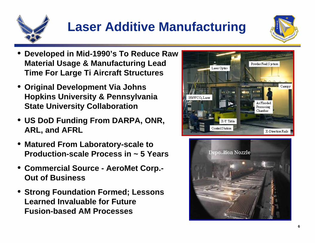
The resulting LAMSM process employs a high-wattage CO2 laser and a powder feed system to deposit wide, thick beads (~ 0.5” x 0.15”) of Ti-6Al-4V onto a substrate. The primary LAMSM deposition system features a 12’ by 4’ by 4’ deposition chamber, a 19kW CO2 laser, a proprietary beam delivery head which moves along the vertical (Z) axis of the deposition chamber, a translation stage which moves the chamber in the X and Y directions beneath the laser beam, a powder delivery system, an off-set powder feed nozzle, and the associated control systems. Part preforms are built in a layer-by-layer fashion by translating the substrate beneath the laser beam along a pre-programmed path. An over-pressure of high-purity argon is maintained in the deposition chamber to prevent oxidation of the titanium during the process and an inert carrier gas is used to transport the powder to the processing zone. The result of the process are LAMSM preforms which require heat treatment and machining to become finished parts.
Additive Manufacturing of Aerospace Alloys for Aircraft Structures
RTO-MP-AVT-139 3 - 3
UNCLASSIFIED/UNLIMITED
UNCLASSIFIED/UNLIMITED
The U.S. Department of Defense played a critical role in funding and managing the development of LAMSM for use in producing aircraft structures. The initial ONR/DARPA investment was followed by investments from the Army, Navy, and Air Force.5 This follow-on funding combined with inter-agency and industry collaboration enabled LAMSM to mature from an experimental laboratory system into a commercial process capable of producing aerospace-quality Ti-6Al-4V hardware in a span of approximately five years. Unfortunately business pressures led to the discontinuation of AeroMet operations in mid-2005. However, the foundation developed for the use of fusion-based AM processes for the production of aerospace hardware remains, and the technological, procedural, and fiscal lessons learned provide invaluable information for organizations developing derivative technologies.
1.3 Overview of AFRL/ML LAMSM R&D Activities Beginning in 1998, AFRL/ML took a lead role in planning, funding, and executing concurrent LAMSM-related R&D activities spanning the range of DoD R&D program elements from basic research (PE 6.1) to manufacturing technology (PE 7.8). The Metals Affordability Initiative (MAI)6,7 provided the primary Air Force funding for LAMSM R&D and facilitated the formation of an industry-wide team to guide the development process. Participants included Boeing, Lockheed Martin, Pratt & Whitney, and AeroMet.
In addition to the MAI effort, AFRL/ML formed a multi-disciplinary team of in-house researchers and technologists to explore applications and challenges for fusion-based AM in general. This AFRL/ML team worked with the MAI team to identify potential high-payoff aerospace applications for the technology, unique aspects of the technology as compared to conventional manufacturing techniques, and barriers to implementing the technology for the manufacture of aerospace hardware. These applications and challenges are highlighted in Section 2.0.
As the MAI projects proceeded and applications and challenges were identified, the need for focused R&D efforts to augment the work being accomplished within the core MAI project became evident. Hence, AFRL/ML initiated various in-house and collaborative projects to address emerging issues. The key results of these projects are highlighted in Section 3.0.
As a result of these AFRL/ML-led activities and associated inter-agency and industry collaborations, LAMSM was qualified as a production method for a select few Air Force aircraft structural components. However, many challenges remain for fusion-based AM of aerospace structures. Some of these challenges are discussed in Section 4.0, which focuses on the future of AM of aerospace alloys.
2.0 APPLICATIONS AND CHALLENGES
The AFRL/ML and MAI teams recognized the potential for AM to revolutionize the aerospace manufacturing industry, with impacts to production lead time, acquisition cost, and performance envisioned. However, significant challenges were also evident in light of the maturity, complexity, and uniqueness of AM combined with the stringent requirements for implementing new aerospace manufacturing processes. A summary of the potential applications for AM, unique aspects of AM, and barriers to implementing AM identified by the joint AFRL/ML - MAI team are described in sections 2.1 – 2.3.
2.1 Potential Aerospace Applications of Additive Manufacturing Within the aircraft industry, AM has four primary applications: the manufacture of components, the repair of components, the manufacture of tooling, and the repair of tooling. The AFRL/ML - MAI team focused on the
Additive Manufacturing of Aerospace Alloys for Aircraft Structures
3 - 4 RTO-MP-AVT-139
UNCLASSIFIED/UNLIMITED
UNCLASSIFIED/UNLIMITED
manufacture and repair of components due to a higher potential payoff. The major sub-sets of components for which AM was deemed to hold potential are discussed in the remainder of section 2.1.
2.1.1 Rib-Web Structural Components
The majority of aircraft sub-structure is comprised of rib-web components such as bulkheads, spars, ribs, and longerons. These components (typically made from aluminium- or titanium-based alloys) feature a mainly planar ‘web’ reinforced with sparsely spaced, essentially perpendicular ‘ribs’ to efficiently carry aircraft loads. These large, major structures are designed to last the entire lifetime of the airframe. They are typically machined out of die forgings, hand forgings, or plate stock, resulting in typical buy-to-fly ratios of 10:1 or higher. Thus, for these types of components, the near net shape process of AM provides several potential benefits including reduced raw material usage, reduced raw material stock size, reduced machining operations, and, when compared to forgings, reduced hard tooling requirements.
These rib-web parts can be difficult to procure in a timely manner, particularly in small quantities (such as when just a few replacement parts are needed), as lead times for obtaining thick-section plate and forgings can be significant. In such a case, AM has the potential to reduce procurement lead time because thinner plate stock and smaller quantities of raw material are required. The extent of lead-time reduction possible with AM is driven by the relative availability of raw materials, lead/cycle times for producing the machining preforms (i.e., thick plate stock, forgings, or additive-manufactured preforms), and lead/cycle times for machining. Other factors also impact procurement lead time, including the availability of forging presses versus AM systems and the lead/cycle times associated with ancillary operations such as stress relief, heat treatment, and non-destructive inspection.
A potential to reduce acquisition cost for rib-web parts also seems apparent considering the reduction in raw material usage, machining operations, and, in some cases, tooling. However, one must consider the cost of the powder, wire, or ribbon feedstock and the cost of the AM process itself before drawing conclusions regarding cost. In many cases, the cost of excess forging or plate material and the associated additional machining operations do not outweigh the cost of the AM process and its feedstock. This is predominantly the case for aluminium components, for which raw material and machining are not overly expensive. However, in the case of titanium components, in which raw material costs are higher and machining is more difficult, AM has a higher potential for reducing acquisition cost. Again, the cost of ancillary operations also must be considered.
The high cost and long lead times often associated with rib-web structural components makes the ability to repair damaged components extremely desirable as well. The utility of AM for repair is impacted by a number of factors, including the ability to inspect the repair and the resulting material for current and future defects, restore the full mechanical capability of the part, the ability to repair the part in situ, and the availability of faster or cheaper repair techniques.
2.1.2 Turbine Engine Cases
Turbine engine cases are major structural components which form the outer surface of the engine and generally are made of titanium- or nickel-based alloys. These cases are typically comprised of thick, cylindrical sections with a small number of low-volume, asymmetric protuberances. The height of these protuberances drives the thickness of the forging preform, and therefore, the buy-to-fly ratio. Hence, buy-to-fly ratios for engine cases can be even higher than those for rib-web components. Thus, similar advantages are expected for AM of these components and reductions in procurement lead time and acquisition cost and the utility of AM for repair are dependant upon essentially the same mitigating factors.
Additive Manufacturing of Aerospace Alloys for Aircraft Structures
RTO-MP-AVT-139 3 - 5
UNCLASSIFIED/UNLIMITED
UNCLASSIFIED/UNLIMITED
2.1.3 Engine Blades and Vanes
Engine blades and vanes are typically comprised of complex airfoil-shaped sections, some of which contain internal cooling passages. These components are often made of titanium- or nickel-based alloys via precision die forging or investment casting (and, hence, have fairly low buy-to-fly ratios), can be quite expensive to procure, and typically experience significant wear and/or damage during their service life. Because little reduction in buy-to-fly ratio is possible, the AM process offers little advantage for component manufacturing. However, the utility of AM for repair has the potential to be significant for blades and vanes, as these components are often repaired or refurbished as part of a typical engine overhaul. AM has the potential to compete with existing repair methods and to enable previously impossible repairs in certain circumstances. In this case, cost and restoration of mechanical performance are the key factors.
2.2 Unique Aspects of Additive Manufacturing The ability to apply AM to the production and/or repair of the components described in Section 2.1 is predicated not only on the ability of AM to be competitive with conventional manufacturing methods in terms of schedule and acquisition cost, but also on its ability to deliver parts with both sufficient and repeatable mechanical performance. In this regard, AM has many unique aspects when compared to wrought products and forgings. These include the hybrid nature of the resulting part, which includes both substrate and deposit, the complexity of the deposition process, and the effect of both of these on the development of process-property relationships.
The hybrid nature of parts produced via AM makes components produced in this manner quite different from those produced using conventional manufacturing methods. For instance, in most cases, the AM substrate and deposit are two entirely different product forms with different characteristic microstructures and slightly different chemical compositions. Additionally, the frames of reference for mechanical anisotropy in the substrate and deposit regions are different. For example, if the substrate is a wrought plate, the frame of reference is fixed by the longitudinal (L), transverse (T), and short transverse (S) directions of the rolling process and many properties are known to be slightly different in each of these directions. However in the deposit, the frame of reference typically is defined with respect to the axis of the focused energy source and the relative direction of travel of the energy source, and therefore varies as the deposition path varies. A typical frame of reference for deposition places the Z direction parallel to the focused energy source, the X direction parallel to the direction of energy source translation, and the Y direction perpendicular to both Z and X; the specific relationship between orientation within the reference frame and mechanical properties depends on the details of the deposition process. Finally, the transition zone between the substrate and the deposit has its own unique characteristics. This lack of microstructural homogeneity within a single part which results from the hybrid nature of AM presents potential difficulties in characterizing and predicting structural performance and in designing parts for AM. (Related difficulties are encountered when using fusion welding for the fabrication of complex aircraft assemblies.)
The complexity of the AM deposition process also distinguishes it from conventional manufacturing techniques. One obvious complexity of the deposition process is that two different raw materials are required: the substrate, which can be as simple as a piece of wrought plate or as complicated as a die forging or precision casting; and the deposition feedstock, which can be as simple as pre-alloyed wire or ribbon or as complicated as elemental blends of metallic powder. Hence, the impact of differences in substrate and deposition feedstock characteristics on the resulting deposit characteristics must be considered. Another complexity is the large number of process variables inherent in the deposition process. These variables can be grouped into two categories: those selected during system design and those selected during process design.
Additive Manufacturing of Aerospace Alloys for Aircraft Structures
3 - 6 RTO-MP-AVT-139
UNCLASSIFIED/UNLIMITED
UNCLASSIFIED/UNLIMITED
System design parameters include the choice of energy source type and power/size, energy source delivery/focusing method, feed mechanism for the feedstock, and translation mechanisms for the substrate and/or energy source. Part-specific process design parameters include the selection of the size and shape of the deposit, total power and power intensity distribution of the energy source, translation path (including line spacing and layer thickness), translation speed, and feedstock flow rate. These part-specific process parameters not only vary from part to part, but also frequently vary locally within a single part so that the desired deposit shape can be attained. Additional process parameters arise from post-deposition processing such as heat treatments for stress relief or metallurgical purposes and hot isostatic pressing to heal porosity.
This sizeable number of possible variations in raw materials, deposition systems, and part-specific process variables in turn complicates the development of process-property relationships and appropriate process control procedures. The mechanical properties of metallic parts are largely governed by characteristics such as the composition, morphology, crystallographic texture, and scale of the microstructure; the size, morphology, and distribution of discontinuities; the residual stress state; and spatial gradients in these characteristics. Hence, the relationships between process variables and such characteristics must govern process-property relationships for AM. However, the majority of these characteristics are directly related to transport phenomena such as fluid flow, heat transfer, and diffusion and to metallurgical phenomena such as melting, solidification, solid-state phase transformations, and solid-state deformation. Because AM involves a multitude of complex, interacting physical phenomena, is different for every part-specific manufacturing procedure, and is transient within a given part, the a priori determination of critical parameters for both obtaining the desired mechanical properties and maintaining process control is virtually impossible.
2.3 Barriers to Implementation of Additive Manufacturing While the possibilities for AM intrigue both the materials engineer and the design engineer, they present a great challenge for those responsible for qualification and certification. Typical manufacturing processes for aircraft hardware are well understood and the resulting product forms are well characterized. Hence, process-property relationships are known to the extent that a combination of fixed process agreements and acceptance testing (both non-destructive inspection (NDI) and destructive coupon testing) are sufficient to confirm adequate part performance. Furthermore, statistically derived mechanical properties datasets are available for use in conventional design activities, both product and process specifications are available to ensure adequate and consistent performance of parts, and multiple qualified suppliers are available in the industrial base to enable time- and cost-effective procurement. Unfortunately, in its current state, AM is not sufficiently understood nor characterized such that conventional design practices and process qualification methodologies can be used; therefore no qualified suppliers exist. This lack of maturity in terms of design, qualification, and procurement procedures is the overarching barrier to implementing AM. Specific aspects of this barrier are described in the remainder of this section.
From a purely technical standpoint, AM cannot be considered for the manufacture of aircraft components unless the process is stable and controlled, the resulting mechanical properties are well characterized and sufficiently invariable, the structural performance of AM parts is predictable using conventional design tools, and the ability to accomplish down-stream processes such as machining and drilling is demonstrated. Inherent in these requirements is the need to develop a process specification which requires the monitoring and control of key raw materials, consumables, and process parameters; the development of a fixed practice for each AM component; the verification of each fixed practice via NDI and destructive testing; and part-specific acceptance testing (both NDI and destructive “witness material” testing) to ensure the integrity of parts. Of course, no such specification can be developed without a fair amount of process development and at least a rudimentary understanding of process-property relationships. Once the specification is generated,
Additive Manufacturing of Aerospace Alloys for Aircraft Structures
RTO-MP-AVT-139 3 - 7
UNCLASSIFIED/UNLIMITED
UNCLASSIFIED/UNLIMITED
development of design data must be accomplished using material produced to the requirements of the specification. If the products of the AM process are proven to be robust by exhibiting nearly isotropic and uniform behaviour throughout the entire component (including the substrate) and having low variability from part to part when parts are produced within the limits of the specification, a single design database for a given alloy is feasible. Otherwise, several feature-dependent databases might be required, or, in the worst case, design data will have to be independently generated for each new component. Once design data are available, an assessment of the predictability of structural performance must be conducted. In the case of a robust product (and the associated single database), it is very likely that conventional homogeneous, isotropic, linear elastic strength and lifing tools will adequately predict the behaviour of the components. However, if mechanical properties are sufficiently variable throughout a given component, more advanced strength and lifing tools might be required to adequately predict structural behaviour. Similarly, mechanical properties and their variability must be considered in an assessment of machining and drilling qualities.
From a business standpoint, there are several barriers to achieving the technical maturity just described. First and foremost is the wide variety of processes within the AM family and the associated differences in (usually proprietary) processing approaches. Without some sort of standardization, it is difficult for the aircraft industry to develop a single specification and associated database for AM of a given alloy. Instead, process-specific specifications and databases might be required, which would then lead to increased data requirements, increased specification authoring and maintenance costs, and difficulties in substituting one process for another for procurement purposes (e.g., to avoid a sole source situation). Another business consideration is the possibility of requiring a different design methodology for AM parts. The cost of developing such a methodology and the associated base of analysts would likely preclude the use of AM unless mitigating performance or acquisition cost benefits were anticipated.
While these technical and business considerations have limited the use of AM in the aircraft industry, they are not insurmountable, and, in fact, were surmounted, at least in part, for LAMSM. Instead, in the end, the ultimate barrier to implementing AM is the lack of a clear performance, schedule, or cost benefit for using it. While schedule and cost benefits seem possible, analyses conducted based on current process maturity for LAMSM, for example, do not show the expected advantage over conventional manufacturing techniques for Ti-6Al-4V in most cases. This inability to realize the full potential of the process is related to two main factors: incomplete understanding of the value stream and supply chain for LAMSM; and inability to design an optimized deposition process without significant pre-production development activities. A complete understanding of the value stream for AM, including the impact of market pressures and advancements in existing technologies on this value stream, is key to developing an AM process with the ability to compete with conventional manufacturing in terms of schedule and cost. Such a value stream analysis would help technologists assess the potential of a given AM technique and identify appropriate areas for future investment. However, one key factor in achieving the anticipated AM advantage is already clear: the need to deliver an optimized AM process for a given part without significant pre-production development activities. In its current state of maturity, the LAMSM process requires some amount of trial and error to determine an acceptable fixed practice for a selected part. This fine-tuning diminishes both the cost and schedule benefit of the process, but has the potential to be eliminated as both understanding of process-property relationships improves and modelling and simulation capabilities develop. Another factor impacting the pre-production development cycle is the need to apply a point design philosophy to the qualification of LAMSM for each and every part. The use of the point design approach typically requires the fabrication and testing of multiple destruct articles, leading to increased cost and lead time. Hence, reduction of lead time requires the use of a broader qualification approach.
Additive Manufacturing of Aerospace Alloys for Aircraft Structures
3 - 8 RTO-MP-AVT-139
UNCLASSIFIED/UNLIMITED
UNCLASSIFIED/UNLIMITED
3.0 KEY AFRL/ML LAMSM DEVELOPMENTS
After ascertaining general areas in which LAMSM was expected to be beneficial, the aircraft and engine manufacturers of the MAI LAMSM team identified specific components within existing weapons system programs for which LAMSM was expected to deliver an economic benefit. Those deemed to have the highest near-term pay-off and feasibility were pursued within the MAI program. At the same time, AFRL/ML initiated in-house R&D to augment the MAI effort and to provide a basis for future applications of AM. These activities can be categorized as follows: characterization of process-property relationships for LAMSM (Section 3.1); development of a feasible implementation path for AM (Section 3.2); and development of a generic process qualification method for AM (Section 3.3). Some of these activities were planned and performed jointly with the Boeing MAI team under U.S. Air Force Cooperative Agreement No. F33615-99-2-5216.
3.1 Process – Property Relationships As described in Section 2.2, process-property relationships for AM are complicated by the large number of variables and physical phenomena involved in the process. However, in the case of LAMSM of Ti-6Al-4V, preliminary results from development activities indicated that this particular AM process yielded strength properties which were just slightly anisotropic and had variability comparable to wrought material over the range of development articles produced.8 Hence, the urgency of developing detailed process-property relationships was somewhat diminished. In spite of this apparent robustness of the LAMSM process, internal AFRL/ML research on microstructure evolution during laser deposition of Ti-6Al-4V demonstrated that changes in process variables could impact microstructure and discontinuity evolution and, therefore, mechanical properties.9,10 Moreover, the preliminary LAMSM development articles did not cover a wide range of processing space, and no attempt was made to determine the limits of the processing window.
Consequently, AFRL/ML undertook independent R&D efforts to make a preliminary assessment of the robustness of the LAMSM process for Ti-6Al-4V. This assessment was conducted in two parts: by investigating the impacts of powder properties (powder production method and mesh size distribution), deposition trajectory, and geometric feature type (linear features versus intersections) on properties of a simulated bulkhead test component; and by joining with the Boeing MAI team and investigating the impact of gross variations in specific energy input and time between subsequent deposition passes on properties in thin- & thick-walled deposits. The results of these efforts can be summarized as follows:
• Sound simulated bulkhead test components exhibiting typical LAMSM mechanical properties can be produced using the standard LAMSM process provided that PREP (plasma rotating electrode) powder is used, regardless of the mesh size distribution of the powder.
• The use of GA (gas atomized) powder requires yet-to-be-determined changes to the standard LAMSM process to produce sound simulated bulkhead test components and therefore is not recommended for use in LAMSM at this time.
• The use of two different deposition trajectories did not cause a statistically relevant difference in tensile strength, fatigue crack growth rate, or fracture toughness properties of the simulated bulkhead component. This result indicates that the LAMSM process might not be terribly sensitive to deposition trajectory in real components, but does not support eliminating deposition path from any fixed practice agreement required by a LAMSM process specification at this time.
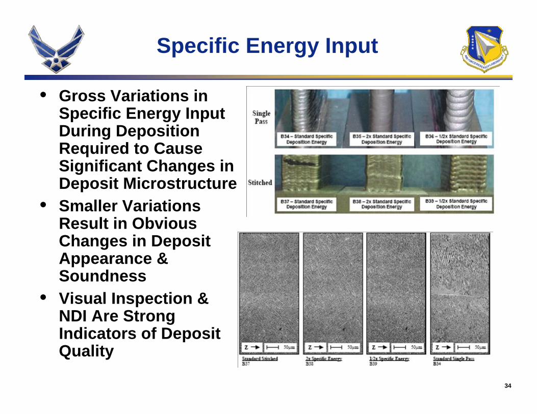
• Gross variations in specific energy input during deposition (from less than 50% to over 200% of the standard input) cause variations in deposit appearance/geometry (as determined via visual inspection)
Additive Manufacturing of Aerospace Alloys for Aircraft Structures
RTO-MP-AVT-139 3 - 9
UNCLASSIFIED/UNLIMITED
UNCLASSIFIED/UNLIMITED
and soundness (as determined via ultrasonic inspection) prior to causing significant variations in microstructure and, thus, mechanical properties, of sound deposit material. Therefore, visual appearance and NDI results are strong indicators of deposit quality.11,12
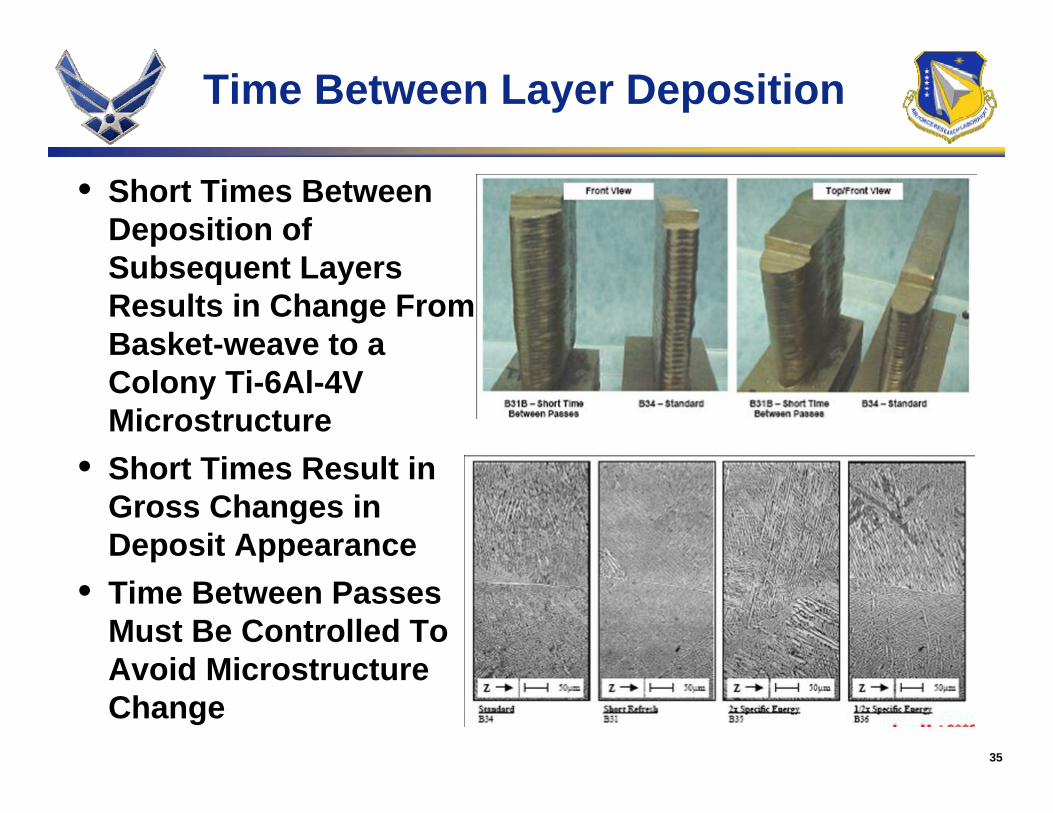
• Testing of deposits made with variations in the time between the deposition of subsequent layers revealed a strong sensitivity of deposit strength, fatigue, and fracture properties to these variations. The differences in mechanical properties in these specimens have been linked directly to differences in deposit microstructure caused by differences in solid-state cooling rates. Based on this result, it is clear that consideration of time between subsequent passes must be considered during the design of deposition trajectories with the specific minimum time between passes depending on the specific geometry of a given part. 11,12
• Lack-of-fusion discontinuities can be generated during LAMSM of Ti-6Al-4V, but do not appear to occur within the standard LAMSM operating window. Furthermore, lack-of-fusion discontinuities cannot be consistently eliminated via HIP and do cause the expected detriment to fatigue and fracture properties. However, ultrasonic tomography is extremely effective in detecting lack of fusion and appears to over-estimate the actual flaw size. Hence, lack of fusion must be eliminated via process design and control and implications of process robustness and NDI capability must be considered for LAMSM of fracture critical hardware.12,13
3.2 Implementation Path for Additive Manufacturing of Aircraft Structures One key step in transitioning a new manufacturing process or product is developing a feasible implementation strategy. Oftentimes, such strategies are ill devised and focus more on near-term payoffs than long-term benefits of implementing the new technology. In the case of LAMSM for Ti-6Al-4V, preliminary assessments of near-term payoffs tempted the joint AFRL/ML – MAI team to focus implementation efforts on large, complex, high-volume, fracture-critical hardware. However, upon a detailed assessment of the maturity of LAMSM and the great effort required to apply LAMSM to such hardware, a more reasonable implementation strategy was developed.14 This strategy targeted medium-sized, simple-geometry, low-volume, high-margin-of-safety, non-safety-of-flight-critical parts first and aimed to transition to higher-volume, medium-margin-of-safety, non-safety-of-flight-critical parts in the near term and to increasingly complex and critical parts as process maturity increased. Such a strategy reduced the risk of implementing LAMSM for the early-adopting weapons systems while providing additional time for maturing LAMSM, developing a production-based design database, and assessing production capacity capabilities. This strategy proved successful, as LAMSM was eventually qualified for the production of two non-safety-of-flight-critical airframe components.15 Hence, the experience of the AFRL/ML – MAI team demonstrated the importance of considering a feasible implementation path when developing and transitioning new manufacturing technologies.
3.3 Qualification of Additive Manufacturing of Aircraft Structures As revealed in Section 2.3, process qualification is a major concern for transitioning any new process into the aircraft design and manufacturing community. Legacy manufacturing methods for metallic materials have well-established specifications and design databases, and therefore protocols for qualifying processes and suppliers are similarly well-established. Hence, specifications, design databases, and qualification protocols must be made available for LAMSM and similar new technologies before they can gain wide acceptance in the aircraft industry. However, achieving these milestones requires significant investment and technical achievement. Determining acceptable procedures and protocols for qualifying new production processes and approving vendors to execute these processes requires extensive knowledge of the details of the entire process and its supply chain and, more specifically, the key characteristics of the process. The complexity of the
Additive Manufacturing of Aerospace Alloys for Aircraft Structures
3 - 10 RTO-MP-AVT-139
UNCLASSIFIED/UNLIMITED
UNCLASSIFIED/UNLIMITED
qualification process increases with process complexity, yet the qualification process must remain tenable if it is to be widely applied. Thus, a manageable strategy for qualifying the LAMSM process is needed before widespread application of the technology is possible.
Based on these realities, the AFRL/ML – MAI team devised a qualification approach based on the approach introduced by the American Welding Society to qualify fusion welding processes.16 This approach aims to use the concept of Procedure Qualification Records for specific deposit geometries and Welding Procedure Specifications for specific part deposition procedures. If the LAMSM analogs of the PQR and WPS are included in the industry-wide process specification, a clear path to process qualification emerges. Design databases for specific deposit features can be generated, and the use of LAMSM will be able to expand. A similar strategy is expected to be applicable to related AM processes. However, the specific details of the PQR/WPS approach remain to be determined within the airframe materials and processes community.
4.0 THE FUTURE OF ADDITIVE MANUFACTURING OF AEROSPACE ALLOYS
Sections 1 through 3 illustrate part of the great potential AM holds for the aerospace community. To date, R&D activities have focused predominantly on LAMSM of Ti-6Al-4V for airframe components. The difficulties inherent in such applications have been clearly delineated. While the technology still remains a curiosity in the aerospace community, the widespread use of such a process for the manufacture of structural components is not imminent. However, technologists within the aerospace community have not abandoned R&D efforts in the area of AM. Activities continue to address issues such as fundamental scientific understanding of AM processes and their key characteristics; improvements in process design and control capabilities via the development of modelling and simulation tools; inclusion of advanced machining concepts into AM processes; and reduction of cost via value stream analysis, AM system design, and process optimization. It is imperative that the scientific and technical community continue these activities if the benefits of lead time and/or cost reduction via true “art-to-part” AM or are ever to be realized.
The future of AM is also envisioned to advance beyond the production of monolithic parts and into the realm of producing advanced materials, functionally graded materials (FGM), and smart structures. As the understanding of the physics of the AM process improve, the feasibility of achieving such goals becomes more realistic. However, the path to flying the clearly heterogeneous FGM and smart structures is fraught with enormous challenges in the areas of structural design, process qualification, and structural certification. While materials and manufacturing engineers develop the know-how to build truly hybrid and/or graded structures, the design and design verification communities must concomitantly develop structural sizing and lifing tools and the associated qualification and certification techniques if these structures are ever to find their way into aircraft structure.
5.0 SUMMARY AND CONCLUSIONS
A team of AFRL/ML technologists in collaboration with industry counterparts from the MAI consortium planned, managed, and executed a series of R&D efforts to successfully transition LAMSM for producing select aircraft structures. In so doing, the team also provided a framework for future AM R&D by assessing the potential benefits and barriers to implementation for AM and devising suitable implementation and qualification paths for such technologies. AM R&D efforts continue with the aim of enabling true process optimization and control for AM and cost-effective AM in the future.
Additive Manufacturing of Aerospace Alloys for Aircraft Structures
RTO-MP-AVT-139 3 - 11
UNCLASSIFIED/UNLIMITED
UNCLASSIFIED/UNLIMITED
6.0 ACKNOWLEDGEMENTS
The authors would like to acknowledge the support of AFRL/MLLM, AFRL/MLSC, AFRL/MLSA, AFRL/MLMP, and ASC/AAA and the cooperation of Kevin Slattery (Boeing), David Chellman (Lockheed Martin), David Alexander (Pratt & Whitney), Frank Arcella and David Abbott (formerly of AeroMet Corp.) in conducting the efforts described in this paper.
7.0 REFERENCES
[1] Bourell, David L.; Beaman Jr., Joseph J., “Freeform fabrication - History and current processes”, Proceedings of Symposium on Rapid Prototyping of Materials, pp. 3-17, 2002.
[2] Das, Suman, Joseph J. Beamam, Martin Wohlert, David L. Bourell, “Direct laser freeform fabrication of high performance metal components”, Rapid Prototyping Journal, Vol. 4, No. 3, pp. 112 – 117, 1998.
[3] DARPA “Flexible Fabrication in Titanium (FFTi)” Program, U.S. Government Contract Number N00014-95-C-0029.
[4] Abbott, D., and F. Arcella, “Laser Forming Titanium Components”, Advanced Materials & Processes, ASM International, Vol. 153, No. 5, pp. 29 to 31, 1998.
[5] Arcella, F. G. Froes, F. H., “Producing Titanium Aerospace Components from Powder Using Laser Forming”, JOM, Vol. 52; No. 5, pp. 28-30, 2000.
[6] Bayha, T., D. Evans, D. Furrer, and A. Poole, “Metals Affordability Initiative Consortium”, Advanced Materials & Processes, ASM International, Vol. 160, No. 5, pp. 30 to 32, 2002.
[7] Martin, R., and D. Evans, “Reducing Costs in Aircraft: The Metals Affordability Initiative Consortium”, JOM, Vol. 52, No. 3, pp. 24-28, 2000.
[8] F. G. Arcella, D. H. Abbott, and M. A. House, “ Titanium alloy structures for airframe application by the laser forming process”, AIAA-2000-1465, 41st AIAA/ASME/ASCE/AHS/ASC Structures, Structural Dynamics, and Materials Conference and Exhibit, Atlanta, GA, Apr. 3-6, 2000.
[9] Kobryn, P.A., E.H. Moore, and S.L. Semiatin, “The effect of laser power and traverse speed on microstructure, porosity, and build height in laser-deposited Ti-6Al-4V”, Scripta Mater., Vol. 43, pp. 299-305, 2000.
[10] Kobryn, P.A. and S.L. Semiatin, “Microstructure and texture evolution during solidification processing of Ti-6Al-4V”, J. mat. Proc. Tech., Vol. 135, pp. 330-339, 2003.
[11] Slattery, K. et al.,” Effects Of Deposition And Thermal Processing Variables On Laser Additive Manufactured Ti-6Al-4V”, Presentation at AeroMat 2003, 11 June 2003.
[12] Slattery K.T. et al., “Processing/Microstructure/Property Relationships in Laser Deposited Ti-6Al-4V”, Presentation at AeroMat 2004, 10 June 2004.
[13] Slattery K.T. et al., “Effects of Discontinuities in Laser Additive Manufactured Ti-6Al-4V”, Presentation at AeroMat 2005, 9 June 2005.
Additive Manufacturing of Aerospace Alloys for Aircraft Structures
3 - 12 RTO-MP-AVT-139
UNCLASSIFIED/UNLIMITED
UNCLASSIFIED/UNLIMITED
[14] Kobryn, P.A., et al., “Rapid Fabrication Of Replacement Components Via Laser Additive Manufacturing Of Titanium”; 6th Joint FAA/DoD/NASA Conference on Aging Aircraft, San Francisco, CA, 16 – 19 September, 2002.
[15] Boyer, R.R., and R.D. Briggs, “Titanium Cost Reduction for Boeing Aircraft”, Materials Forum, Vol. 29, pp. 47 - 54, 2005.
[16] American Welding Society: http://www.aws.org
Additive Manufacturing of Aerospace Alloys for Aircraft Structures
RTO-MP-AVT-139 3 - 13
UNCLASSIFIED/UNLIMITED
UNCLASSIFIED/UNLIMITED
MEETING DISCUSSION – PAPER NO: 3
Author: P. Kobryn
Discusser: D. Dicus
Question: Assuming further research in additive manufacturing is warranted, what are the characteristics the candidate process should have in order to justify the investment required to develop the required complete value stream analysis and the development of automatic process control?
Response: 1. Applicability to multiple structural alloys. 2. A well established, competitive raw material supply chain capable of providing high quality materials on demand. 3. An expectation that true “art-to-part” capability can be achieved with appropriate investment (including design database).
Discusser: C. Bampton
Question: Would the same problem exist with lack of value-stream benefit for complex parts produced at a very low rate (say 10 parts per year versus 500 parts per year)?
Response: To a certain extent, the LAM process does become more attractive for low-rate production. However the pre-production development costs will still be significant. Therefore, the LAM process will not compare favorably to hog-outs for low-rate production but might compare favorably to forgings or castings.
Discusser: X. Wu
Question: Is Ti-6-4 a wrong material for additive manufacturing since it is developed for thermal mechanical processing? Perhaps one should try material designed for casting. That could be one way to get out of the problem in microstructure control.
Response: Certainly, the selection of alloy is important. By selecting an alloy with favorable solidification characteristics or developing an alloy with such characteristics, one could influence the ability to obtain suitable homogenous microstructures. However, consideration must be given to the difficulty of obtaining acceptance of a new or less common alloy.
Discusser: A. Pinkerton
Question: What do you consider to be the key variable in the process (as well as specific energy)? Is there a mass-related parameter that is key?
Response: Specific energy input is clearly a key variable. However, it is influenced by several system variables such as input energy, travel speed, and powder flow rate. At this point it is not clear if specific energy is the correct parameter to use in process control.
Discusser: J. Allen
Question: Could you please give us your view on the use of automatic on-line control systems in future additive manufacturing systems?
Additive Manufacturing of Aerospace Alloys for Aircraft Structures
3 - 14 RTO-MP-AVT-139
UNCLASSIFIED/UNLIMITED
UNCLASSIFIED/UNLIMITED
Response: I believe that the development and implementation of autonomous control systems is key to the future success of additive manufacturing.
Discusser: R. Bondaruk
Question: What is the Technology Readiness Level (TRL) for LAM?
Response: The TRL for LAM of Ti-6AI-4V for producing non-safety-of-flight-critical structure using a point design philosophy is 7. The TRL of laser deposition for repair of certain components is 9, but TRL is slightly different for every application.
Discusser: P. Carroll
Question: Will CAM packages for deposition be as comprehensive as those for conventional machining?
Response: I do not see fusion-based additive manufacturing as being a big enough market to justify investment by a commercial CAM software provider. Therefore, AMers will likely be forced to adapt commercially available packages to suit their needs. Alternatively, individual AMers could (and do) develop their own CAM software. As process models and process control tools are developed, their integration into the CAM software will be important. The mechanism for this integration is yet to be determined.
Comment: Author thinks that current CAM packages are sufficiently developed. (I don’t agree!) Also, author needs to link between modeling and CAM output.
Response: I did not intent to intimate that CAM development for AM is not important to future advancement of these technologies, as it clearly is important. My answer was intended to express my opinion regarding the development of a state-of-the-art “CAM for AM” software package that would be marketed to those performing AM. In this case, I do not believe that payoff is worth the investment and follow-on support that would be required. Another road block is the proprietary nature of many AM process details. Hence, I expect AMers to develop the tools they need rather than support the development to industry-wise software packages.
Discusser: P. Brown
Question: Do you think that LAM will be overtaken by other rapid manufacture techniques?
Response: Yes. I suspect that fusion-based additive manufacturing techniques which employ less costly capital equipment, require less energy input, or enable faster deposition rates will overtake the laser-based process for most applications. The laser-based processes have their niche in applications which take advantage of the small heat affected zones which can result. However, I do believe that fusion-based AM will hold advantages over casting and solid-state RP methods for years to come, primarily due to the possibility of building higher quality parts.
1
Additive Manufacturing of Aerospace Alloys for Aircraft
StructuresDr. Pamela A. Kobryn
Dr. Jaime S. Tiley, Mr. Larry P. Perkins, Mr. Neal R. OntkoMaterials & Manufacturing Directorate
Air Force Research Laboratory15 May 2006
Presented at NATO RTO AVT-139 Specialists’ Meeting on Cost Effective Manufacture via Net Shape Processing; 15 – 17 May 2006; Amsterdam, The Netherlands
2
Outline
• Introduction & Background– Additive Manufacturing (AM) of Metallic Materials– The Laser Additive Manufacturing (LAMSM) Process– LAMSM R&D Overview
• Applications & Challenges– Potential Aerospace Applications of AM– Unique Aspects of AM– Barriers to Implementation of AM
• Key LAMSM Developments– Process - Property Relationships – Implementation Path for AM of Aircraft Structures– Qualification of AM of Aircraft Structures
• The Future of AM of Aerospace Alloys• Summary & Conclusions
3
Introduction & Background
• Additive Manufacturing (AM) of Metallic Materials• The Laser Additive Manufacturing (LAMSM) Process• AFRL/ML LAMSM R&D Overview
4
Additive Manufacturing (AM) of Metallic Materials
• “Additive Manufacturing” Is Selective Addition of Material to a Functional Substrate
• Often Describes a Fusion-based Deposition Process (Akin to Fusion Welding), but Not Always (e.g., Cold Spray)– Energy Sources: Laser, Electric Arc, Electron Beam, Plasma Beam– Feedstock Types: Powder, Wire, Ribbon– Translation Mechanisms: CNC Stage, Gantry, Multi-axis Robot
• Result Is a Hybrid Manufacturing Method– Substrates Can Be Wrought Sheet / Plate, Forgings, Castings,
or Damaged Parts– AM Adds High-aspect-ratio / Low-volume Features to the Substrate– Post-AM Processing Required (e.g., Heat Treatment, Machining)
• AM Used for Best Combo of Part Performance, Cost, and Schedule
5
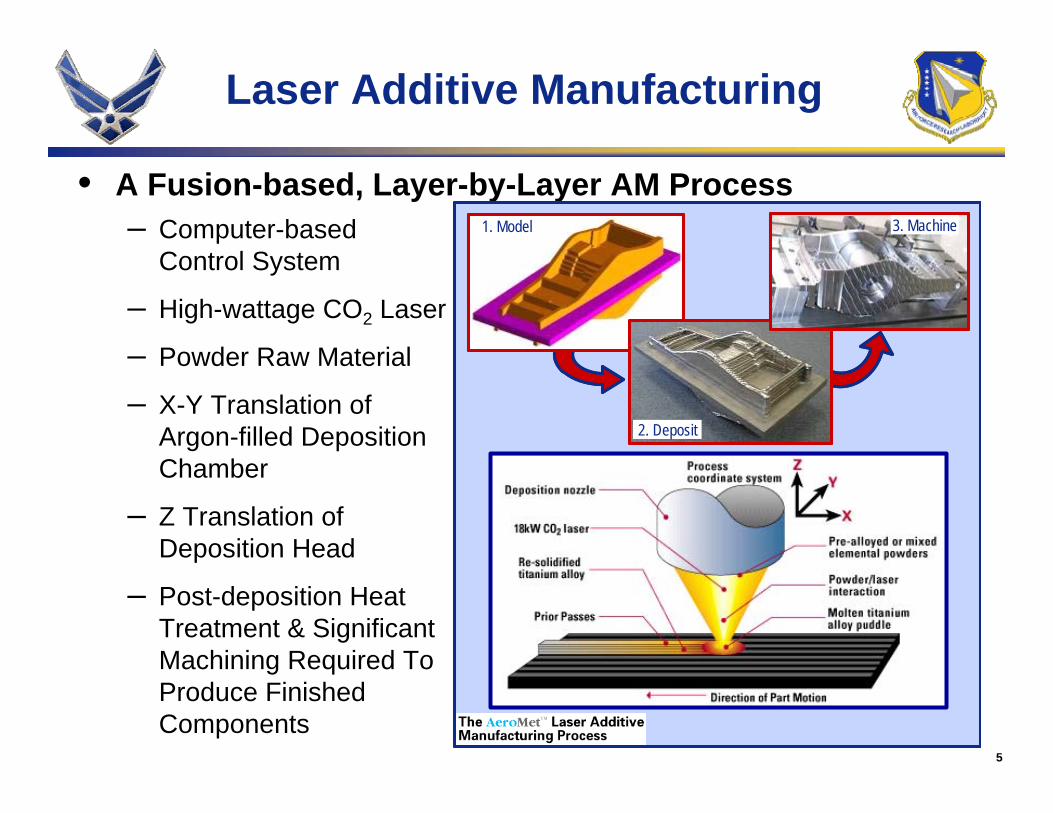
Laser Additive Manufacturing
• A Fusion-based, Layer-by-Layer AM Process– Computer-based
Control System
– High-wattage CO2 Laser
– Powder Raw Material
– X-Y Translation of Argon-filled DepositionChamber
– Z Translation of Deposition Head
– Post-deposition Heat Treatment & SignificantMachining Required To Produce Finished Components
1. Model 3. Machine
2. Deposit
1. Model 3. Machine
2. Deposit
1. Model 3. Machine
2. Deposit
6
Laser Additive Manufacturing
• Developed in Mid-1990’s To Reduce Raw Material Usage & Manufacturing Lead Time For Large Ti Aircraft Structures
• Original Development Via Johns Hopkins University & Pennsylvania State University Collaboration
• US DoD Funding From DARPA, ONR, ARL, and AFRL
• Matured From Laboratory-scale to Production-scale Process in ~ 5 Years
• Commercial Source - AeroMet Corp.-Out of Business
• Strong Foundation Formed; Lessons Learned Invaluable for Future Fusion-based AM Processes
7
AFRL/ML LAMSM R&D Overview
• Metals Affordability Initiative– AFRL/ML-led Aerospace Metals Industry Consortium
• Includes OEMs, Parts Manufacturers, and Raw Material Suppliers• Projects Selected Competitively & Managed by the Consortium
– Funded LAMSM R&D Projects from 1999 – 2004• Facilitated Formation of Industry-wide LAM Team• Participants Included Boeing, Lockheed Martin, Pratt & Whitney,
& AeroMet
• AFRL/ML In-house R&D– Formed Multi-disciplinary Team of In-house Researchers &
Technologists To Guide Development & Collaborate with MAI Team– Executed Focused In-house R&D To Augment MAI Effort
• OUTCOME: Identified Applications & Challenges, Then Developed a Successful Implementation Process
8
Applications & Challenges
• Potential Aerospace Applications of AM
• Unique Aspects of AM
• Barriers to Implementation of AM
9
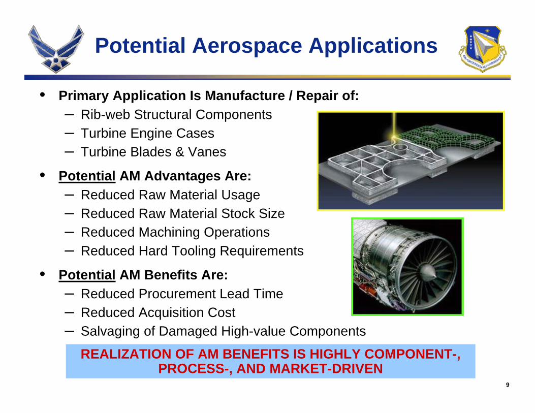
REALIZATION OF AM BENEFITS IS HIGHLY COMPONENT-, PROCESS-, AND MARKET-DRIVEN
Potential Aerospace Applications
• Primary Application Is Manufacture / Repair of:– Rib-web Structural Components– Turbine Engine Cases– Turbine Blades & Vanes
• Potential AM Advantages Are:– Reduced Raw Material Usage– Reduced Raw Material Stock Size– Reduced Machining Operations– Reduced Hard Tooling Requirements
• Potential AM Benefits Are:– Reduced Procurement Lead Time– Reduced Acquisition Cost– Salvaging of Damaged High-value Components
10
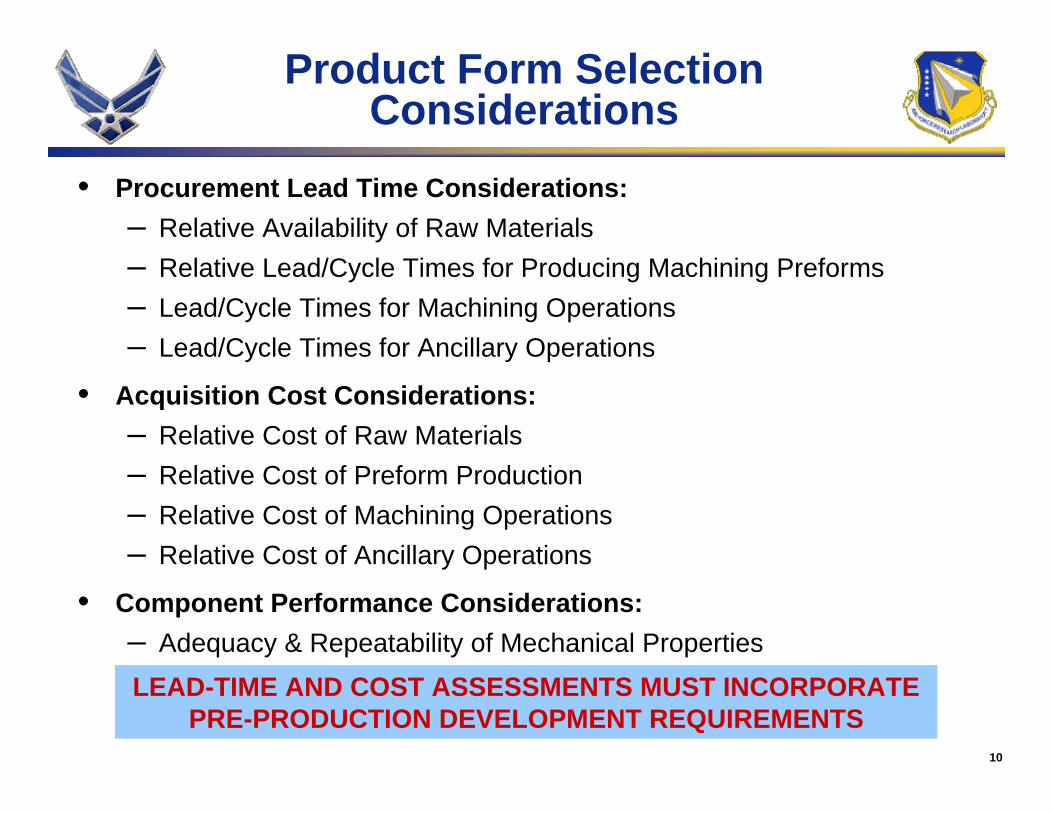
LEAD-TIME AND COST ASSESSMENTS MUST INCORPORATEPRE-PRODUCTION DEVELOPMENT REQUIREMENTS
Product Form Selection Considerations
• Procurement Lead Time Considerations:– Relative Availability of Raw Materials– Relative Lead/Cycle Times for Producing Machining Preforms– Lead/Cycle Times for Machining Operations– Lead/Cycle Times for Ancillary Operations
• Acquisition Cost Considerations:– Relative Cost of Raw Materials– Relative Cost of Preform Production– Relative Cost of Machining Operations– Relative Cost of Ancillary Operations
• Component Performance Considerations:– Adequacy & Repeatability of Mechanical Properties
11
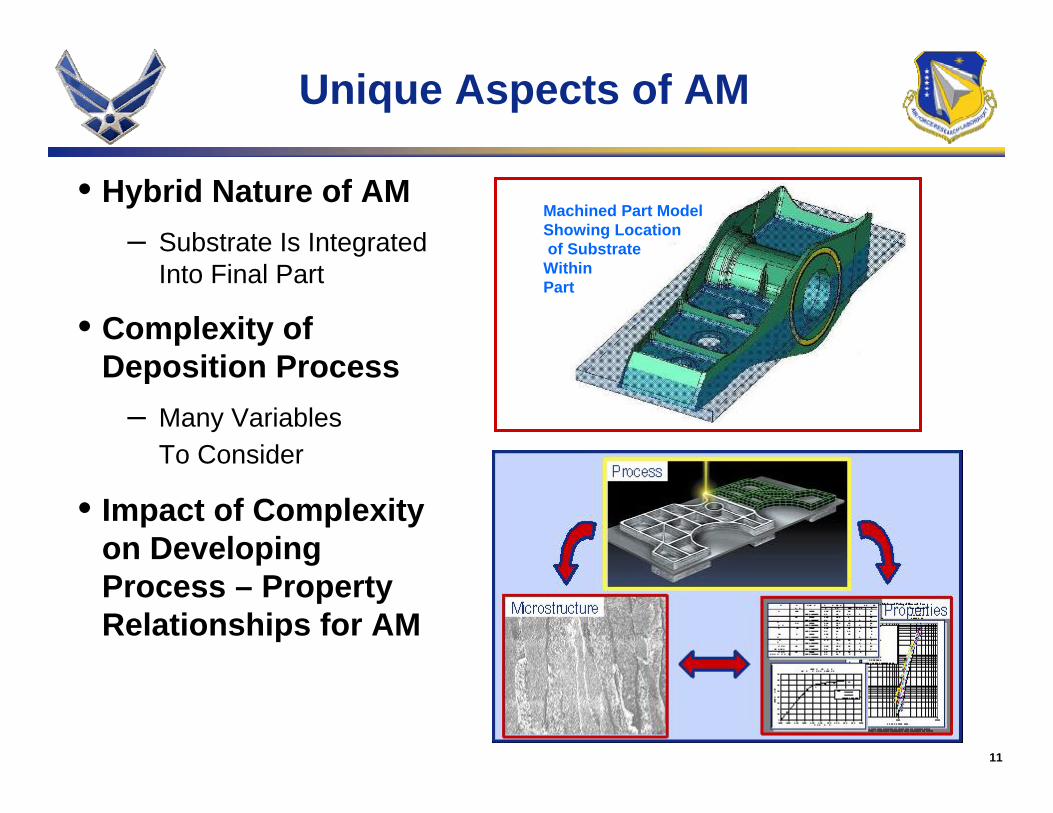
Unique Aspects of AM
• Hybrid Nature of AM– Substrate Is Integrated
Into Final Part
• Complexity ofDeposition Process
– Many VariablesTo Consider
• Impact of Complexityon Developing Process – Property Relationships for AM
Machined Part ModelShowing Locationof Substrate
WithinPart
12
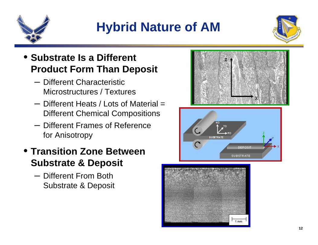
Hybrid Nature of AM
• Substrate Is a Different Product Form Than Deposit– Different Characteristic
Microstructures / Textures– Different Heats / Lots of Material =
Different Chemical Compositions– Different Frames of Reference
for Anisotropy
• Transition Zone Between Substrate & Deposit– Different From Both
Substrate & Deposit
13
Complexity of Deposition Process
• Multitude of Complex, Interacting Physical Phenomena Involved
– Heat Transfer, Fluid Mechanics, Continuum Mechanics
– Melting, Solidification, Solid-State Phase Transformations, Grain Growth, Diffusion
• Many Process Variations Possible
• Many Important Characteristics of the Deposit
14
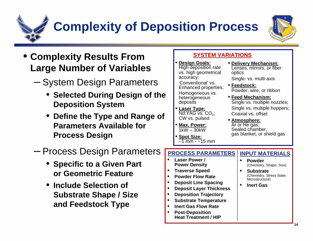
Complexity of Deposition Process
• Complexity Results From Large Number of Variables– System Design Parameters
• Selected During Design of the Deposition System
• Define the Type and Range of Parameters Available for Process Design
– Process Design Parameters• Specific to a Given Part
or Geometric Feature• Include Selection of
Substrate Shape / Size and Feedstock Type
PROCESS PARAMETERS• Laser Power /
Power Density• Traverse Speed• Powder Flow Rate • Deposit Line Spacing• Deposit Layer Thickness• Deposition Trajectory• Substrate Temperature• Inert Gas Flow Rate• Post-Deposition
Heat Treatment / HIP
INPUT MATERIALS• Powder
(Chemistry, Shape, Size)
• Substrate(Chemistry, Stress State, Microstructure)
• Inert Gas
• Delivery Mechanism:Lenses, mirrors, or fiber opticsSingle- vs. multi-axis
• Feedstock:Powder, wire, or ribbon
• Feed Mechanism:Single vs. multiple nozzles;Single vs. multiple hoppers;Coaxial vs. offset
• Atmosphere:Ar or He gas; Sealed chamber, gas blanket, or shield gas
SYSTEM VARIATIONS• Design Goals:
High deposition rate vs. high geometrical accuracy;‘Conventional’ vs. Enhanced properties;Homogeneous vs. heterogeneous deposits
• Laser Type:Nd:YAG vs. CO2; CW vs. pulsed
• Max. Power:1kW – 30kW
• Spot Size:~1 mm - ~15 mm
15
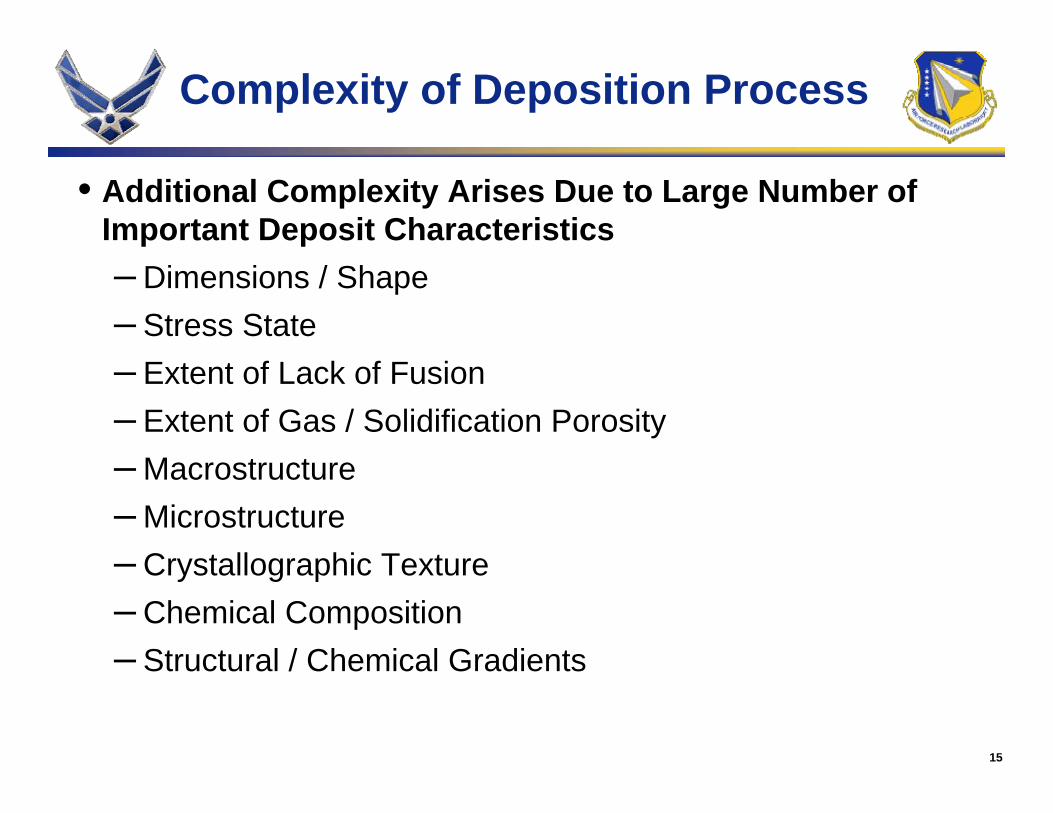
Complexity of Deposition Process
• Additional Complexity Arises Due to Large Number of Important Deposit Characteristics– Dimensions / Shape – Stress State – Extent of Lack of Fusion– Extent of Gas / Solidification Porosity– Macrostructure– Microstructure– Crystallographic Texture– Chemical Composition – Structural / Chemical Gradients
16
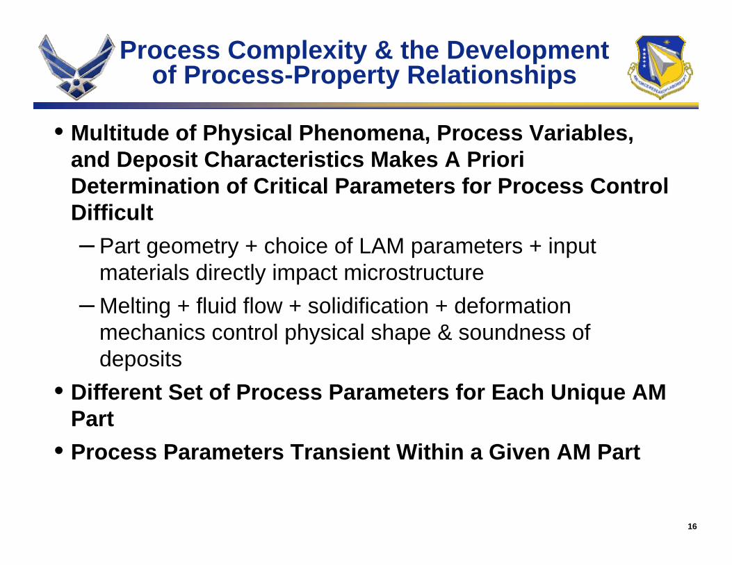
Process Complexity & the Development of Process-Property Relationships
• Multitude of Physical Phenomena, Process Variables, and Deposit Characteristics Makes A Priori Determination of Critical Parameters for Process Control Difficult– Part geometry + choice of LAM parameters + input
materials directly impact microstructure– Melting + fluid flow + solidification + deformation
mechanics control physical shape & soundness of deposits
• Different Set of Process Parameters for Each Unique AM Part
• Process Parameters Transient Within a Given AM Part
17
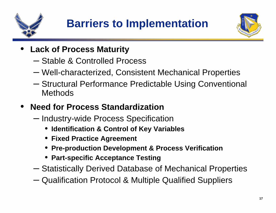
Barriers to Implementation
• Lack of Process Maturity– Stable & Controlled Process– Well-characterized, Consistent Mechanical Properties– Structural Performance Predictable Using Conventional
Methods
• Need for Process Standardization– Industry-wide Process Specification
• Identification & Control of Key Variables• Fixed Practice Agreement• Pre-production Development & Process Verification• Part-specific Acceptance Testing
– Statistically Derived Database of Mechanical Properties– Qualification Protocol & Multiple Qualified Suppliers
18
Barriers to Implementation
• No Clear Performance, Schedule, or Cost Benefit With AM at Current Maturity Level– Incomplete Understanding of the Complete AM Value
Stream & Supply Chain• Assessment of Viability of AM for Specific Applications
Not Possible• Impact of Market Pressures or Advancements in Other
technologies Not Understood• Areas for Future Investment Not Defined
– No Ability To Design Optimized Process Without Significant Pre-production Development Activities• Process – Property Relationships Not Defined• Modeling & Simulation Tools Not Available• Point Design Required for Every Part
19
Key LAMSM Developments
• Process - Property Relationships
• Implementation Path for AM of Aircraft Structures
• Qualification of AM of Aircraft Structures
20
Process-Property Relationships
• Characteristics of LAMSM Ti-6Al-4V Development Articles:– Properties Similar to Those of Conventional Product Forms– Majority Exhibited Only Slight Anisotropy in Strength Properties– Variability in Strength Properties Similar to That of Wrought Material– Process Appeared Robust, But Small Range of Processing Space
Interrogated
• In-house R&D Highlighted Relationship Between Deposition Parameters and Microstructure
• LAMSM Process Robustness Investigation Focused on:– Changes in Powder Properties & Deposition Trajectory– Gross Variations in Specific Energy Input & Time Between Layer
Deposition
21
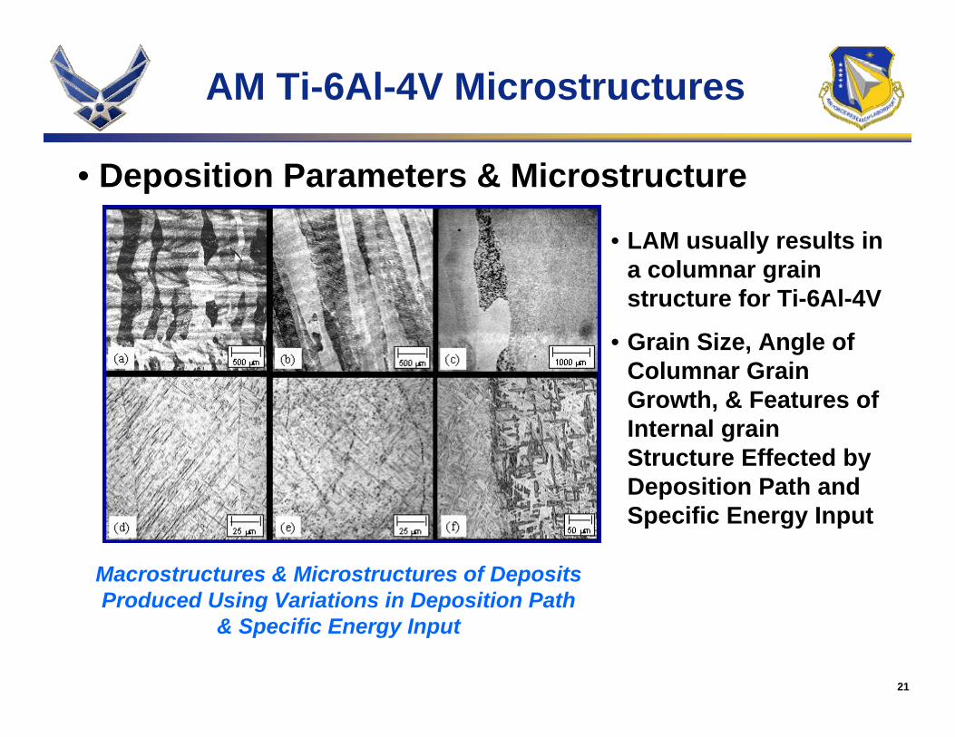
AM Ti-6Al-4V Microstructures
• LAM usually results in a columnar grain structure for Ti-6Al-4V
• Grain Size, Angle of Columnar Grain Growth, & Features of Internal grain Structure Effected by Deposition Path and Specific Energy Input
Macrostructures & Microstructures of Deposits Produced Using Variations in Deposition Path
& Specific Energy Input
• Deposition Parameters & Microstructure
22
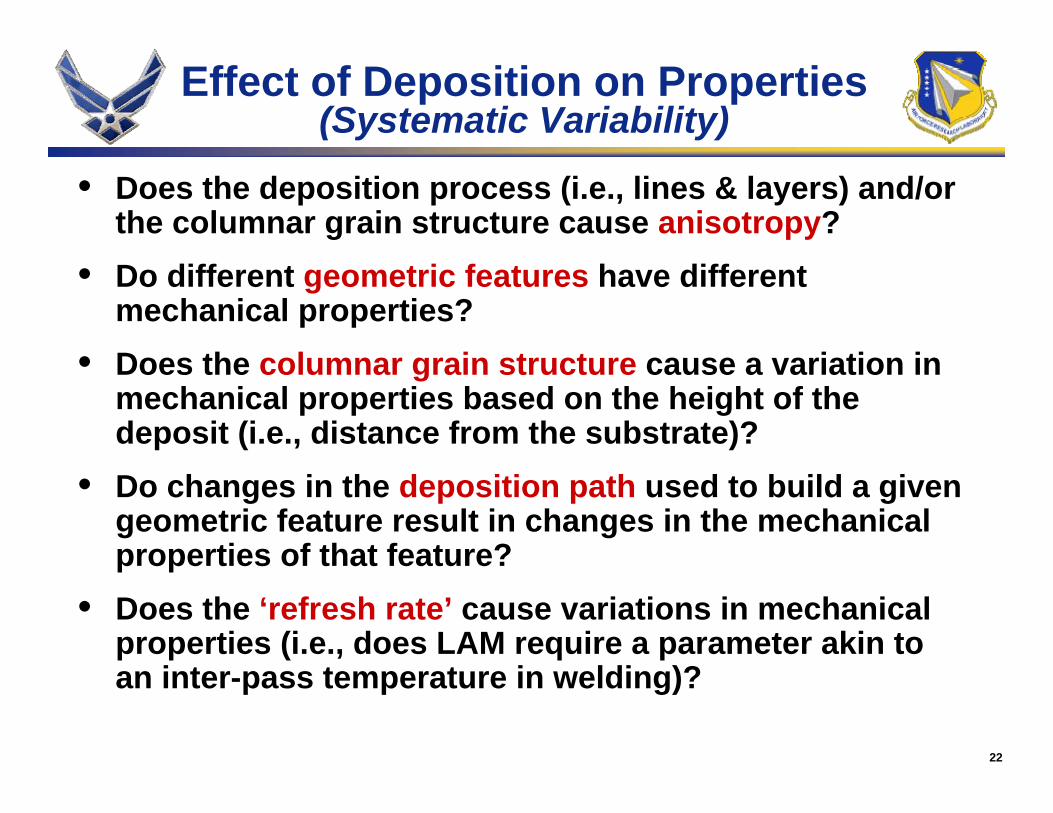
Effect of Deposition on Properties(Systematic Variability)
• Does the deposition process (i.e., lines & layers) and/or the columnar grain structure cause anisotropy?
• Do different geometric features have different mechanical properties?
• Does the columnar grain structure cause a variation in mechanical properties based on the height of the deposit (i.e., distance from the substrate)?
• Do changes in the deposition path used to build a given geometric feature result in changes in the mechanical properties of that feature?
• Does the ‘refresh rate’ cause variations in mechanical properties (i.e., does LAM require a parameter akin to an inter-pass temperature in welding)?
23
vs.
Y Dire
ction
X Direction
X Direction
Z D
irect
ion
vs.
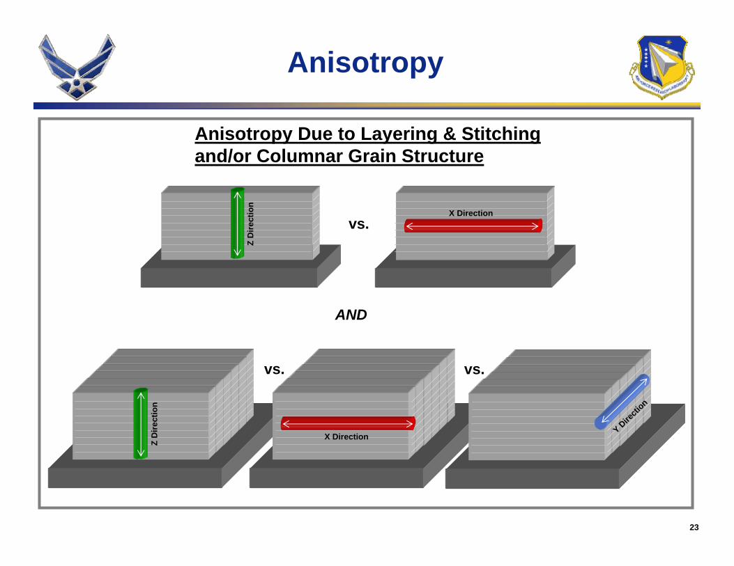
Anisotropy Due to Layering & Stitchingand/or Columnar Grain Structure
vs.
Z D
irect
ion
AND
Anisotropy
24
vs.
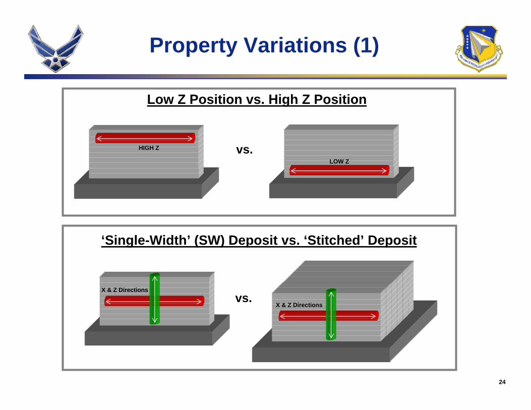
Low Z Position vs. High Z Position
HIGH Z
LOW Z
vs.
‘Single-Width’ (SW) Deposit vs. ‘Stitched’ Deposit
X & Z Directions
X & Z Directions
Property Variations (1)
25
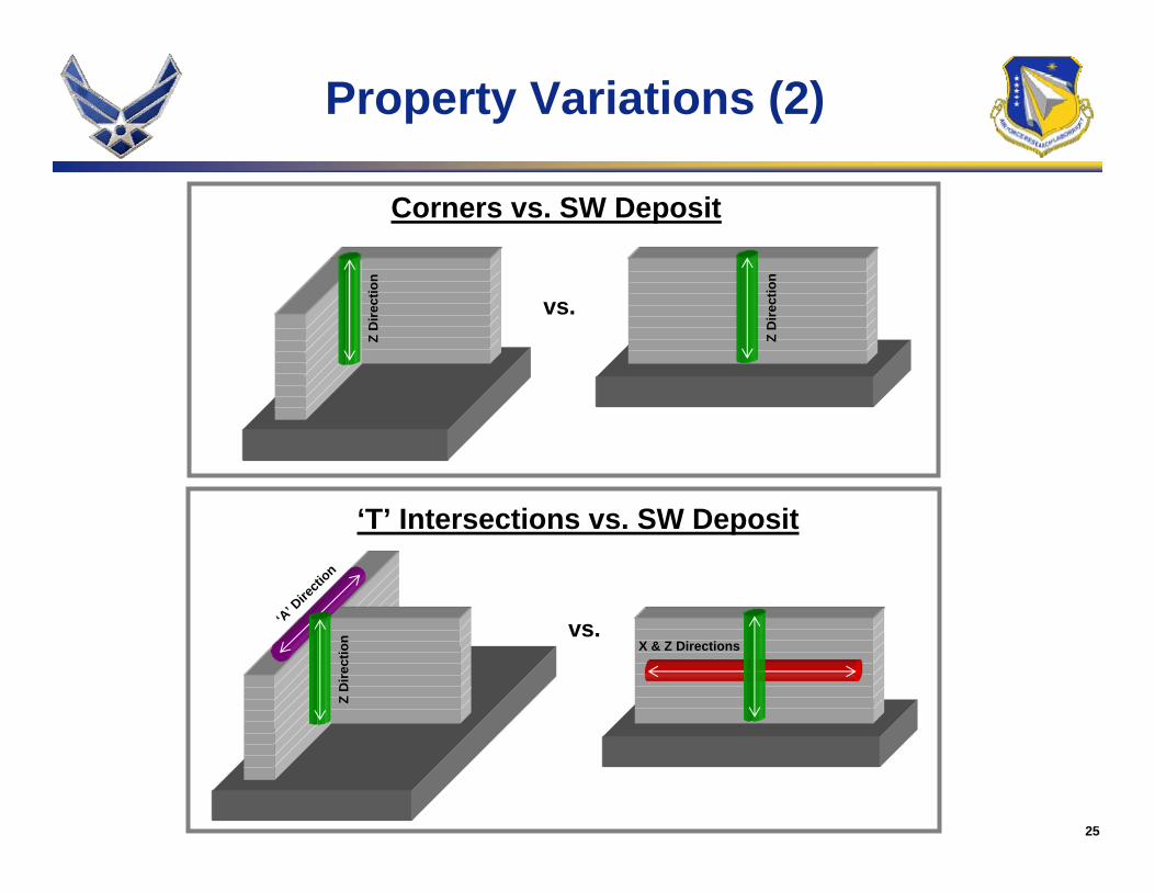
Corners vs. SW Deposit
Z D
irect
ion
vs.
‘T’ Intersections vs. SW Deposit
‘A’ Dire
ction
vs.X & Z Directions
Property Variations (2)
Z D
irect
ion
Z D
irect
ion
26
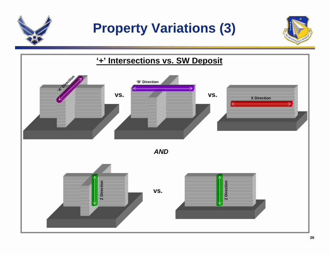
‘+’ Intersections vs. SW Deposit
‘B’ Direction
vs. X Direction
vs.
vs.
Z D
irect
ion
AND
Property Variations (3)
Z D
irect
ion
‘A’ D
irecti
on
27
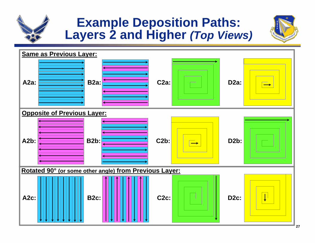
Same as Previous Layer:
A2a: B2a: C2a: D2a:
A2b: B2b: C2b: D2b:
Opposite of Previous Layer:
Rotated 90° (or some other angle) from Previous Layer:
A2c: B2c: C2c: D2c:
Example Deposition Paths:Layers 2 and Higher (Top Views)
28
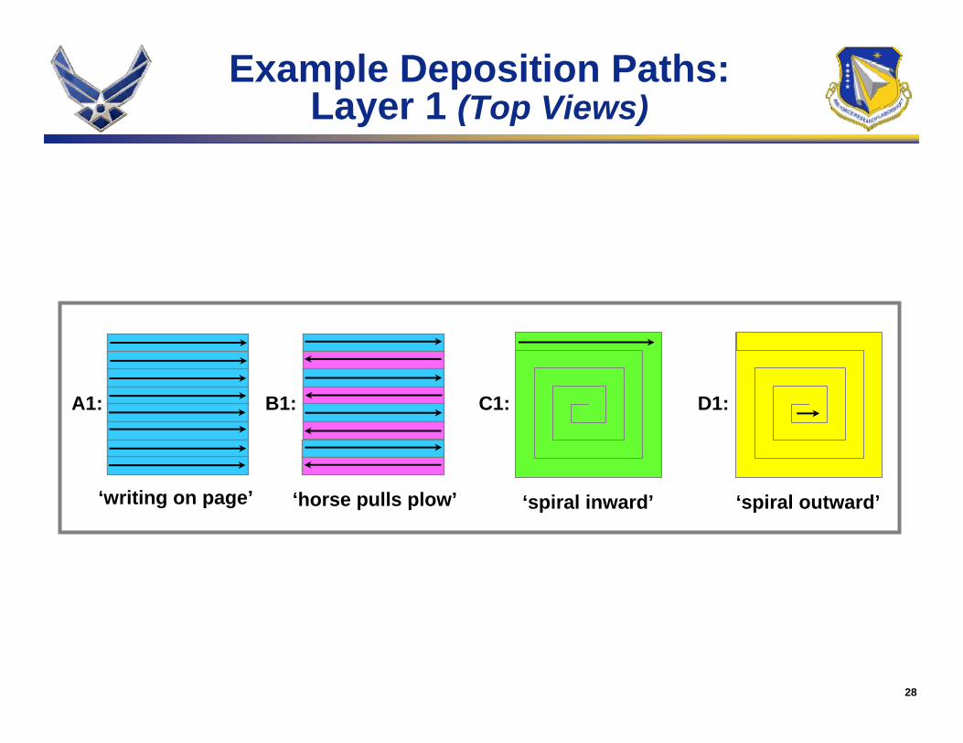
A1: B1: C1: D1:
‘writing on page’ ‘horse pulls plow’ ‘spiral inward’ ‘spiral outward’
Example Deposition Paths:Layer 1 (Top Views)
29
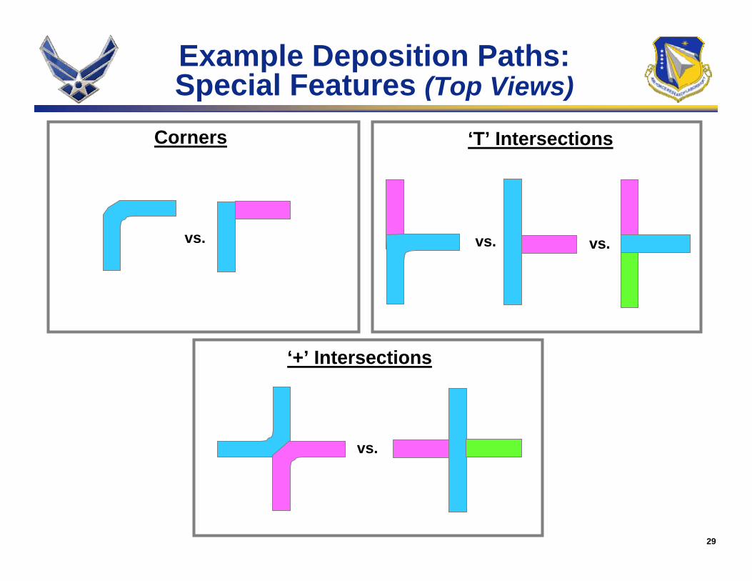
‘+’ Intersections
Corners ‘T’ Intersections
vs.
vs.
vs. vs.
Example Deposition Paths:Special Features (Top Views)
30
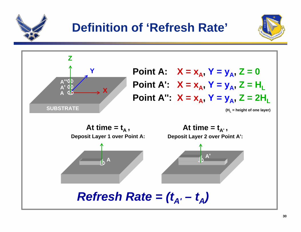
Definition of ‘Refresh Rate’
At time = tA ,Deposit Layer 1 over Point A:
At time = tA' ,Deposit Layer 2 over Point A':
Z
X
Y
AA'A''
Point A: X = xA, Y = yA, Z = 0Point A': X = xA, Y = yA, Z = HL
Point A'': X = xA, Y = yA, Z = 2HL
A A'
Refresh Rate = (tA' – tA)
SUBSTRATE (HL = height of one layer)
31
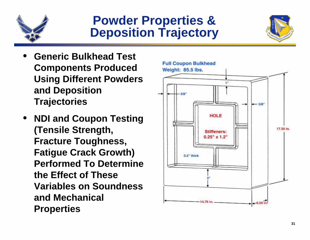
Powder Properties & Deposition Trajectory
• Generic Bulkhead Test Components Produced Using Different Powders and Deposition Trajectories
• NDI and Coupon Testing (Tensile Strength, Fracture Toughness, Fatigue Crack Growth) Performed To Determine the Effect of These Variables on Soundness and Mechanical Properties
32
Powder Properties & Deposition Trajectory
• Sound Deposits w/ Typical Properties Produced Using Standard LAM Parameters & Pre-alloyed PREP Powder, Regardless of Mesh Size
• Use of Gas Atomized Powder Requires Changes to Standard Process
• The Two Chosen Deposition Trajectories Did Not Cause Statistically Relevant Difference in Properties
• Investigation of Differences Between Properties of Various Geometric Features Inconclusive
• Standard LAM Process Appears Robust for Bulkhead-like Geometry
33
Specific Energy Input / Time Between Layers
• Specific Energy Input Intentionally Varied in Single-width & Stitched Deposits– Levels Chosen Were “Standard”, “1/2x Standard”, & “2x Standard”
• Time Between Passes Intentionally Varied in Single-width Deposits
• Visual Inspection, NDI, Coupon Testing, & Metallographic Analysis Performed on All Deposits
34
Specific Energy Input
• Gross Variations in Specific Energy Input During Deposition Required to Cause Significant Changes in Deposit Microstructure
• Smaller Variations Result in Obvious Changes in Deposit Appearance & Soundness
• Visual Inspection & NDI Are Strong Indicators of Deposit Quality
35
Time Between Layer Deposition
• Short Times Between Deposition of Subsequent Layers Results in Change From Basket-weave to aColony Ti-6Al-4V Microstructure
• Short Times Result in Gross Changes in Deposit Appearance
• Time Between Passes Must Be Controlled To Avoid Microstructure Change
36
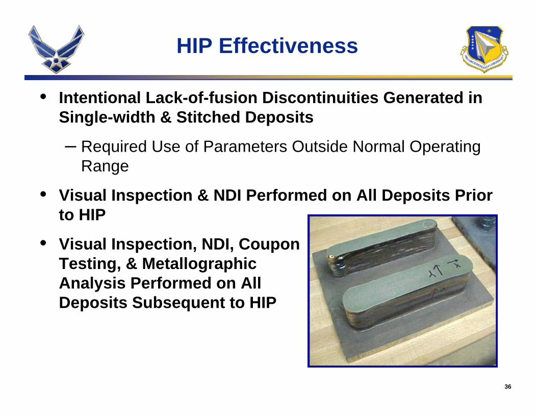
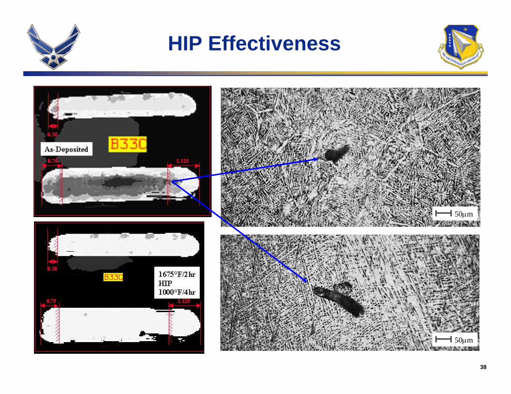
HIP Effectiveness
• Intentional Lack-of-fusion Discontinuities Generated in Single-width & Stitched Deposits
– Required Use of Parameters Outside Normal Operating Range
• Visual Inspection & NDI Performed on All Deposits Prior to HIP
• Visual Inspection, NDI, Coupon Testing, & Metallographic Analysis Performed on All Deposits Subsequent to HIP
37
HIP Effectiveness
• Lack-of-fusion Discontinuities Can Be Produced Using LAMSM, But Rarely Within Standard Operating Window
• LAMSM Lack-of-fusion Discontinuities Cannot be Consistently Eliminated With HIP
• LAMSM Lack-of-fusion Discontinuities Do Cause the Expected Debit to Fatigue & Fracture Properties
• NDI (Ultrasonic Tomography) Is Extremely Effective in Detecting Lack-of-fusion Discontinuities & Appears to Over-estimate Actual Flaw Sizes
• Lack-of-fusion Discontinuities Must be Eliminated Via Process Design & Control
• NDI Capability Must Be Considered for LAMSM of Critical Hardware
38
HIP Effectiveness
50m
50m
39
Implementation Path for Aircraft Structures
• Successful Transition of New Technology to Production of Aircraft Structures Requires an Intelligent Implementation Strategy
• Strategy Must Be Based on an Assessment of Maturity & Risk, Not on Near-Term Payoff
• Early Transition to Components with:– Small to Medium Size– Simple Geometric Features– Low Production Volume Requirements– High Margins of Safety– No Safety-of-Flight Criticality
• Carries Acceptable Risk for Early Adopters • Enables Time for Additional Process Maturation,
Production-based Database Generation, & Production Capacity Assessments
40
Qualification of AM for Aircraft Structures
• Tenable Qualification Protocol for AM Required to Enable Widespread Application
• Protocol Must Be Tied to the Process Specification
• Detailed Knowledge of Key Characteristics Required
• American Welding Society Approach To Qualifying Fusion Welds Holds Potential– Develop Procedure Qualification Records (PQR) for Selected
Geometric Features– Generate Welding Procedure Specifications (WPS) for Specific
Components– WPS Specifies Multiple PQRs– Enables Generation of Generic Mechanical Properties Database &
Expansion of AM Usage
41
The Future of AM of Aerospace Alloys
42
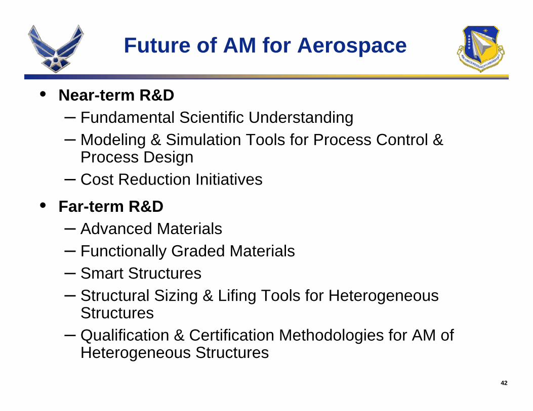
Future of AM for Aerospace
• Near-term R&D– Fundamental Scientific Understanding– Modeling & Simulation Tools for Process Control &
Process Design– Cost Reduction Initiatives
• Far-term R&D– Advanced Materials– Functionally Graded Materials– Smart Structures– Structural Sizing & Lifing Tools for Heterogeneous
Structures– Qualification & Certification Methodologies for AM of
Heterogeneous Structures
43
Summary & Conclusions
44
Summary & Conclusions
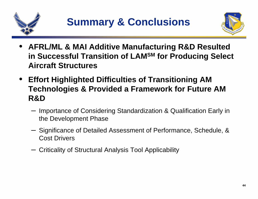
• AFRL/ML & MAI Additive Manufacturing R&D Resulted in Successful Transition of LAMSM for Producing Select Aircraft Structures
• Effort Highlighted Difficulties of Transitioning AM Technologies & Provided a Framework for Future AM R&D– Importance of Considering Standardization & Qualification Early in
the Development Phase
– Significance of Detailed Assessment of Performance, Schedule, & Cost Drivers
– Criticality of Structural Analysis Tool Applicability