drone based additive manufacturing of architectural structures
TRANSCRIPT

Proceedings of the International Association for Shell and Spatial Structures (IASS)
Symposium 2015, Amsterdam
Future Visions
17 - 20 August 2015, Amsterdam, The Netherlands
Drone-Based Additive Manufacturing
of Architectural Structures
Pierre LATTEURa, Sébastien GOESSENS
a, Jean-Sébastien BRETON
a, Justin LEPLAT
a,
Zhao MAb, Caitlin MUELLER
b
a Université catholique de Louvain, Louvain School of Engineering EPL/IMMC,
Civil & Environmental Engineering,
Place du Levant 1 (Vinci), bte L5.05.01, 1348-Louvain-la-Neuve, Belgium,
b Massachusetts Institute of Technology, Department of Architecture,
77 Massachusetts Ave, Cambridge, MA 02139, United States
Abstract
The paper presents the first results of a new collaboration project between MIT and UCL (MISTI
MIT-UCL seed fund), which investigates the feasibility of the construction of building-scale
structures with unmanned aerial vehicles, commonly called drones, according to a procedure
described below:
1. Designing the building by the architect and the engineer;
2. Modeling the building into a CAD/BIM tool;
3. Translating the CAD/BIM model into remote control instructions compatible with the drones;
4. Assembling the structure with the drones.
The major components of the project consists of choosing the best drone-compatible assembly
processes and materials, developing the guiding systems for the drones for both broad large-scale
movements and precise small-scale motions and developing the best possible translation tools between
the CAD/BIM models, and the drone’s remote control instructions.
The paper will emphasize on the results of the first part of the project, related to the construction of
structures made of geometrically modified blocks bonded together, called dricks and droxels.
Keywords: digital fabrication, robotic fabrication, additive manufacturing, unmanned aerial vehicles,
drone
1. Introduction
The contemporary engineering industry has been revolutionized by additive manufacturing via 3D
printers, which are capable of producing geometrically complex mechanical parts quickly and
Proceedings of the International Association for Shell and Spatial Structures (IASS) Symposium 2015, Amsterdam
Future Visions
precisely. As an extension, experimental 3D printers aimed at fabricating full-scale buildings are
currently in development, but they are limited in the size of objects they can produce to the extents of
their print bed, restricting possibilities for building sizes and shapes.
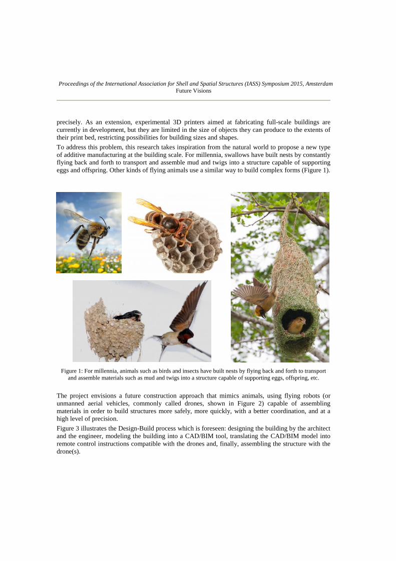
To address this problem, this research takes inspiration from the natural world to propose a new type
of additive manufacturing at the building scale. For millennia, swallows have built nests by constantly
flying back and forth to transport and assemble mud and twigs into a structure capable of supporting
eggs and offspring. Other kinds of flying animals use a similar way to build complex forms (Figure 1).
Figure 1: For millennia, animals such as birds and insects have built nests by flying back and forth to transport
and assemble materials such as mud and twigs into a structure capable of supporting eggs, offspring, etc.
The project envisions a future construction approach that mimics animals, using flying robots (or
unmanned aerial vehicles, commonly called drones, shown in Figure 2) capable of assembling
materials in order to build structures more safely, more quickly, with a better coordination, and at a
high level of precision.
Figure 3 illustrates the Design-Build process which is foreseen: designing the building by the architect
and the engineer, modeling the building into a CAD/BIM tool, translating the CAD/BIM model into
remote control instructions compatible with the drones and, finally, assembling the structure with the
drone(s).

Proceedings of the International Association for Shell and Spatial Structures (IASS) Symposium 2015, Amsterdam
Future Visions
Figure 2: different types of drones
Figure 3: “Drones Compatible Design&Build” process

Proceedings of the International Association for Shell and Spatial Structures (IASS) Symposium 2015, Amsterdam
Future Visions
The project investigates the feasibility of such a building methodology and integrates several distinct
but complementary tasks:
1. Quantification of the energy requirements: under what conditions this construction method
feasible, given the tradeoffs of energy consumption and payload?
2. Development of the ideal assembly process and the adequate construction materials, combined
with a guiding system allowing the drones to move spatially with a suitable accuracy;
3. Development of a material delivery mechanism attached on the drones, able to transport and
deposit construction material(s);
4. Construction of a few small structures characterized by different assembly processes (§2);
5. Development of an interface able to translate CAD/BIM output files into instructions for drone
movements.
This paper presents results from the first phase of this project, focusing on drone guiding systems and
the design of a preliminary material system.
2. Drone compatible assembly processes (DCAP)
Figure 4: Examples of drone compatible assembly processes (DCAP)
Although the use of drones is compatible with the use of common construction materials such as
concrete, steel, masonry, and wood, a given project with a given architecture (e.g. bridge, building,
renovation), may require, on one hand, one specific or a combination of specific DCAPs and, on the
other hand, the development of new materials and construction details.
Proceedings of the International Association for Shell and Spatial Structures (IASS) Symposium 2015, Amsterdam
Future Visions
Given the exploratory character of the project, the focus is first on the development of four DCAPs
based on classical building methods, eventually improved or modified (e.g. new block designs; see
Section 4), as shown in Figure 4 :
1. Structures composed of walls made of cellular concrete blocks bonded together (Fig. 4a);
2. Frames composed of timber and/or steel beams, assembled together (Fig. 4b);
3. Curved structures made of a succession of small amounts of a material that harden and adhere
after being deposited by the drone, using a material such as fiber-reinforced concrete (Fig. 4c);
4. Cast-in-place frames composed of columns and beams made of fiber-reinforced concrete (Fig.
4d). The drones are in this case also be programmed to assemble formworks and remove them
after sufficient material curing.
3. Positioning systems and building accuracy
A drone is often composed of 4 to 8 fixed pitch propellers, and the navigation system is assumed by
different electronic devices as a gyroscope that measures changes in angles (pitch, roll, yaw), cameras,
a GPS which measures the geographical position and a pressure sensor which measures altitude at the
condition that the ground topography is not too rough.
It is typical to consider that the precision needed for construction is on the order of a centimeter but
for more specific tasks such as tightening a bolt, a higher precision around one mm is necessary.
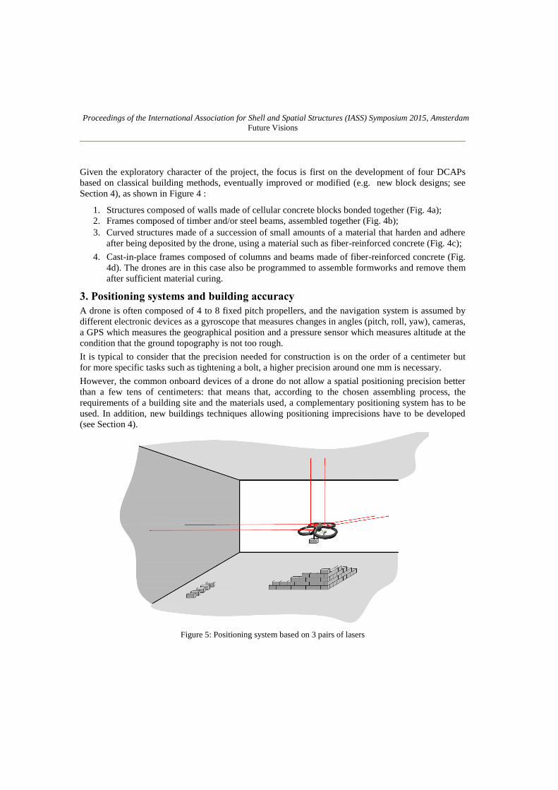
However, the common onboard devices of a drone do not allow a spatial positioning precision better
than a few tens of centimeters: that means that, according to the chosen assembling process, the
requirements of a building site and the materials used, a complementary positioning system has to be
used. In addition, new buildings techniques allowing positioning imprecisions have to be developed
(see Section 4).
Figure 5: Positioning system based on 3 pairs of lasers

Proceedings of the International Association for Shell and Spatial Structures (IASS) Symposium 2015, Amsterdam
Future Visions
This project used a quadrotor drone called the AR.Drone 2.0, developed by Parrot (Figure 9a, [3]). For
the first experiments, image recognition was used with colored tags placed at ground level and on the
structure. This method does not produce acceptable results because it requires complex software
development, coded differently in each situation. Furthermore, it is difficult to always keep tags
within the camera’s field of view when the drone goes down near the ground. Finally, the image
recognition has to be adapted at each stage of the construction as far as the local landscape is
constantly changing (shapes and colors).
Another positioning system being developed in the project is based on a system of several laser
distance meters placed on the drone. The 3 pairs of lasers measure the distance between the drone and
3 screens placed around the construction, as shown in Figure 5. The (x,y,z) position of the drone is
then calculated (accuracy less than 1 cm) and sent in real time to the computer with a wifi connection.
The disadvantage of this solution is that there may be no obstacles between the drone and the screens,
which is quite restrictive. Furthermore, the screen which gives the vertical z position has to be put
above the building, which is only possible if its height is small.
Another positioning system uses the classic GPS system with RTK (Real Time Kinematics). RTK is a
technique used to enhance the precision of a GPS system, which uses information from a fixed
reference station to provide real-time correction of the signal. This can provide a rather good
positioning accuracy, which nevertheless remains very sensitive to the constructed topography around
the construction site (Figure 6).
Figure 6: Global Positioning System GPS combined with the RTK system.
Another possible positioning system combines a classic GPS “non-accurate” positioning system
coupled to an automatic theodolite instrument (Figure 7). The GPS is used to move the drone over

Proceedings of the International Association for Shell and Spatial Structures (IASS) Symposium 2015, Amsterdam
Future Visions
long distances, such as between the storage area and the construction area, and then, the theolodite
station is used to accurately place the drone at the right place.
Figure 7: Combination GPS/automatic theodolite
4. Drone compatible masonry: dricks
The feasibility of a construction mode based on rigid rectangular bricks placed above each other has
already been demonstrated recently by researchers led by R. D’Andrea at ETH Zurich, with the
construction of a 6-m-tall tower composed of 1500 foam modules assembled by 4 quadrocopters [1].
Other promising experiments have been presented by Q. Lindsey et al. at the University of
Pennsylvania, who used drones to build tower-like small-scale cubic structures made of modular parts
assembled with magnets [2]. While these developments are promising, there is a need for further
investigation into structural units that can be used additively in drone-based construction, where less
precision is available compared to manual or other robotic methods.
To address this need, this paper presents a new unit for drone-based construction called the drick, a
portmanteau of “drone” and “brick.” In many building applications, masonry units need to be
assembled next to and on top of each other at a precision of less than 1 cm. To reach this objective, we
developed dricks with geometry such that they naturally align themselves exactly at the right place
despite an inaccurate dropping position of several cm. Currently, three kinds of dricks have been
Proceedings of the International Association for Shell and Spatial Structures (IASS) Symposium 2015, Amsterdam
Future Visions
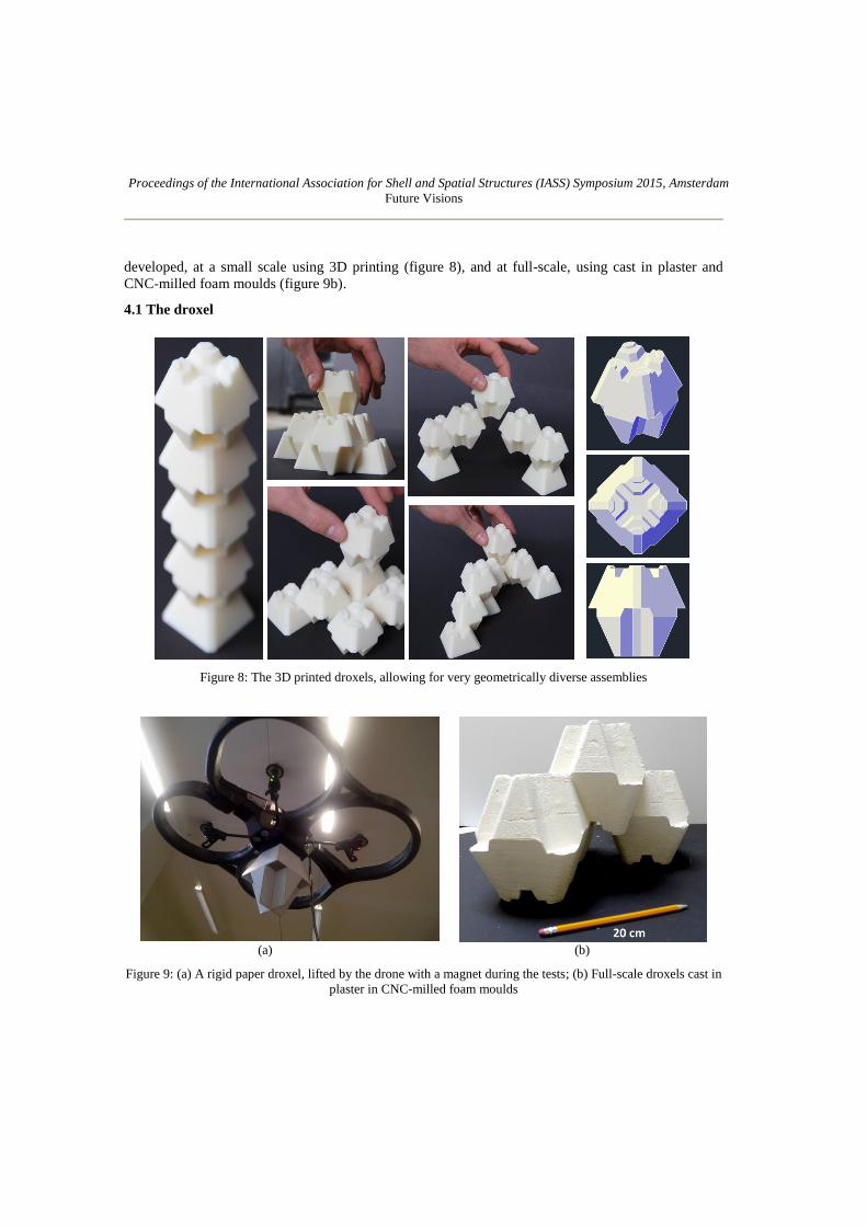
developed, at a small scale using 3D printing (figure 8), and at full-scale, using cast in plaster and
CNC-milled foam moulds (figure 9b).
4.1 The droxel
Figure 8: The 3D printed droxels, allowing for very geometrically diverse assemblies
(a) (b)
Figure 9: (a) A rigid paper droxel, lifted by the drone with a magnet during the tests; (b) Full-scale droxels cast in
plaster in CNC-milled foam moulds

Proceedings of the International Association for Shell and Spatial Structures (IASS) Symposium 2015, Amsterdam
Future Visions
Droxel is here defined as a portmanteau of “drone” and “voxel;” a voxel is a three-dimensional pixel,
and the term is used here to allude to the space-filling potential of the droxel masonry elements. The
droxel was shaped to allow a maximum contact area with its neighbors. Figure 8 shows a few possible
configurations: columns, arches, cantilevers, 3D volumes but any structure can be shaped droxel by
droxel to create an endless number of designs. Each Droxel is locked in position by its neighbors, up
to 10 (8 on the beveled sides, 1 each on the top and bottom). This means that besides providing a very
accurate self-alignment–up to a 5 cm tolerance for full scale droxels in both horizontal directions–they
also provide rigidity to the structure. Figure 9 shows a droxel lifted up by the drone by an electro-
magnet during testing, and full-scale cast droxels made of plaster (future versions will be made of
light-weight concrete to achieve a reasonable payload).
4.2 The conical interlocking drick (CID)
The conical interlocking drick, or CID, is locked in position by up to four blocks, as shown in
Figure 10. CID’s design provides a positioning tolerance even for the last block closing a structure.
However, special blocks have to be designed in order to realize corners. The CIDs can be made of
reinforced concrete or fiber reinforced concrete, and even be completely made from an insulating
material used as formwork for in situ concrete pouring.
Figure 10: The conical interlocking drick (CID)
4.3 The rounded conical interlocking drick (RCID)
The Rounded Conical Interlocking Drick (RCID) is an alternative of the CID, with a rounded shape
topped by two cones, allowing for the creation curved walls as shown in Figure 11.

Proceedings of the International Association for Shell and Spatial Structures (IASS) Symposium 2015, Amsterdam
Future Visions
²
Figure 11: The rounded conical interlocking drick (RCID)
5. Compatibility between CAD models and DCAPs
Figure 12: A simple example illustrating the translation between a CAD model
and a drone-based construction

Proceedings of the International Association for Shell and Spatial Structures (IASS) Symposium 2015, Amsterdam
Future Visions
Figure 13: Flying routes that the drone has to follow between the storage location
and the dropping points
This simple experiment demonstrates the feasibility of the translation of a CAD model into drone-
compatible instructions. The structure chosen for the experiment is a planar closed structure made of
one layer of dricks and was modeled by 6 nodes and 6 straight lines forming right angles (Figure 12).
All the dricks are first placed by hand on defined places, waiting to be lifted and transported by the
drone. The CAD model is saved into a .dxf file, which is then treated by a C++ subroutine that divides
each line into a number of (x,y) points equal to the number of dricks per line. The C++ subroutine
then creates a .txt file with all the flying routes that the drone has to follow between the storage
location and the dropping points (Figure 13).
6. Energy requirements of the drone-based construction
The calculation of the energy costs related to the classical construction of a building-scale structure
must include:
1. Before construction: embodied energy related to factors such as the extraction of building
materials, transportation, and treatment (blast furnace for steel, sawmill for wood, concrete
plant);
2. During construction: energy from factors related to the way the building is assembled, such as
the digging of foundations and the erection of the structure, most commonly achieved by
cranes;
3. After construction: operational energy requirements such as heat and conditioning, cleaning, as
well as post-usage energy related to dismantling and recycling.
Among all these factors, energy related to the assembly of the building is most impacted by the use of
drones. While it seems clear that assembly by drones requires more energy than conventional
construction methods using cranes, it is desirable to quantify the impact of such an assembly mode. In
other words, considering the whole process of construction from the extraction of the material until
disassembly and recycling, two questions should be answered:

Proceedings of the International Association for Shell and Spatial Structures (IASS) Symposium 2015, Amsterdam
Future Visions
1. For conventional construction, what is the average percentage of the energy cost related to
building assembly, with respect to its total energy cost?
2. For assembly with drones, what is the average value of the energy cost, compared to the
conventional assembly and erection methods, usually achieved with cranes?
Other aspects such as the mode of propulsion and energy source of the drones are included in the
project’s objectives. Finally, the use of drones supplied by a portable wire connected to the ground
could also be considered, which would be a compromise between drones equipped with batteries and
drones supplied with fuel. These questions will be investigated in future work.
7. Conclusion
The first steps of the project tend to confirm the feasibility of large scale drone-based constructions
and show its potential. Given the recent (and continuing) extraordinary developments of drone
technologies, the future of construction may undergo a revolution in the coming decades, with science
fiction becoming a reality.
The use of drones is not necessarily incompatible with common construction materials such as
concrete, steel, masonry, and wood. Nevertheless, while the drone-based construction is likely more
energy-intensive and expensive in general, the project aims to strategically identify situations and
conditions in which it offers the most potential benefits.
Other major components of the project will consist of selecting the best assembly processes, making
laboratory strength tests over full scale dricks and droxels, developing the guiding systems and
developing the best possible translation tools between the Computer-Aided Drafting (CAD) models
and the drone’s remote control instructions. The study itself is broad: just as multiple ways exist in
digital modeling software to represent and generate the same structure, multiple ways exist for a drone
to erect a building.
Acknowledgement
The authors wish to thank the MISTI MIT-UCL Seed Fund, for sponsoring part of this research, in
addition to the following individuals, all from the UCL:
- J. Hendrickx and F. Wielant for having given a few drones for our experiments, but also for the
help in “decoding” the codes;
- A. Bertholet and S. Courtois for their help in the “customization” of our drones;
- B. Herman for the help in the 3D printings.
References
[1] Augugliaro, F. et al, The Flight Assembled Architecture installation: Cooperative construction
with flying machines, Control Systems, IEEE , Volume 34, 2014.
[2] Lindsey Q. et al, Construction of Cubic Structures with Quadrotor Teams, Robotics, Science
and systems VII, 2011, MIT Press, Cambridge, Massachusetts, 2012.
[3] Piskorski S., Brulez N., Eline P., D’Haeyer F., AR.Drone Developer Guide. Revision SDK 2.0,
2012.