sub marine explorer field records - · pdf fileconfederate submarine h.l. hunley dating to...
TRANSCRIPT

SUB MARINE EXPLORER HAER CZ-5
Located along the beach of Isla San Telmo, Pearl Islands CZ-5 Isla San Telmo Former Panama Canal Zone Canal Zone (Panama)
PHOTOGRAPHS
WRITTEN HISTORICAL AND DESCRIPTIVE DATA
REDUCED COPIES OF MEASURED DRAWINGS
FIELD RECORDS
HISTORIC AMERICAN ENGINEERING RECORD National Park Service
U.S. Department of the Interior 1849 C Street NW
Washington, DC 20240-0001
HISTORIC AMERICAN ENGINEERING RECORD
SUB MARINE EXPLORER
Location:
UTM Coordinates:
HAER No. CZ-5
Located along the beach of Isla San Telmo, Pearl Islands, Isla San Telmo, Former Panama Canal Zone, Canal Zone (Panama)
17, 737265.80 E, 916069.46 N The coordinate was derived from Google Earth Pro v5 on December 9, 2010. The imagery dates from January 7, 2008.
Rig/Type of Craft: Submarine
Principal Dimensions:
Dates of Construction:
Length: 36' Beam: 10' Height: 10'-6 V2" Weight: 88,161 pounds Displacement: 116,745 pounds
1865-67
Architect/Engineer: Julius W. Kroehl with assistance from Ariel Patterson
Builder: Julius W. Kroehl and Ariel Patterson
Disposition:
Significance:
Historians:
Shipwreck
Sub Marine Explorer is significant as one of only five known submarines dating to pre-1870 and as an example of early submarine technology. The submarine was, and remains, even as a ruin, an amazing technological and engineering achievement of the mid-nineteenth century.
James P. Delgado and John W. McKay, 2007
Project Information: After the discovery of Sub Marine Explorer in 2001, two preliminary seasons of documentation were undertaken in 2001 and 2002. More comprehensive field work was done in 2004 and 2006 under permit by the Government of Panama through the Instituto Nacional de Cultura. The Council of American Maritime Museums (CAMM) and the Historic American Engineering Record (HAER) of the National Park Service through the Sally Kress Tompkins Fund for historic vessel documentation conducted the work in part, along with the National Oceanic and
SUB MARINE EXPLORER HAERNo. CZ-5
Page 2
Atmospheric Administration's Office of Ocean Exploration (grant number NA050AR4601168). LIDAR scanning of the exterior ofExplorer in 2004 was accomplished through the support of Doug DeVine and Carlos Velazquez of Pacific Survey and Epic Scan, Ltd., and Eco-Nova Productions, Ltd. Sea Hunter's film company also supported the field work. Final documentation of the submarine was possible through the support of the Waitt Institute for Discovery and the Institute of Nautical Archaeology. The field survey team (2001-2008) consisted of Todd Croteau (HAER), James Delgado, Mike Fletcher, Warren Fletcher, Ann Goodhart, Bert Ho, Don Johnson, Michael McCarthy, Larry Murphy, Joshua Price, Mark Ragan, Joe Valencic, Frederick Hanselmann, Clyde Paul Smith, Jacinto Almendra, Ghislaine Maxwell, and Karl Vandenhole. Todd Croteau (HAER) produced the large-format photographs and prepared the field sketches, and John McKay completed the interpretive reconstruction drawings in 2007.
Reconstructing Sub Marine Explorer proved to be a difficult task. Years on the beach of Isla San Telmo have caused the destruction of some parts ofExplorer. Because of the loss of original material, conjectural reconstruction of approximately 10 percent of the submarine had to be done. The team made conjectural assumptions based on the fragmentary information at hand, as well as information from other primary and secondary sources. Some questions are likely not to be resolved unless excavation of the site recovers missing portions of the craft or additional archival details become available. As the "reconstruction" of Explorer continued, another area of consideration was the terminology to be applied to naming the various parts of the submarine. While terms for some parts might seem simple enough, such as "conning tower" and "ballast tank," some of the terms were in use in 1864-1866, when submarine construction was in its infancy. The primary source ultimately used in the reconstruction drawings was W.W.W. Wood's report dating from February 2, 1865, which contains some two dozen technical terms. Other technical terms from contemporary sources were also employed in the description.
SUB MARINE EXPLORER HAERNo. CZ-5
Page 3
HISTORY
Design and Construction Julius W. Kroehl designed the submersible Sub Marine Explorer in 1863. He built it along with shipbuilder Ariel Patterson at Patterson's shipyard at 273 First Street (now Kent Avenue), near North Third Street on the shores of the East River in Brooklyn, New York, between 1864 and 1865. Julius Kroehl was a Prussian immigrant who arrived in New York City on July 29, 1844, and became a naturalized U.S. citizen on October 26, 1849. He had a range of experience, beginning as a partner in the daguerreotype firm "Messrs. Kroehl & Vetter" ca. 1851. Kroehl was the first assistant on construction and the assistant engineer for the Crystal Palace, which was erected for the 1853 World Fair in New York City. From 1854 to 1855, he formed the company, Husted and Kroehl, Submarine Engineers, while also continuing his work in cast-iron. As a result of his work on the glass and cast-iron Crystal Palace, he was granted a patent in 1855 for machinery to bend the flanges of wrought-iron beams. During the following year, Kroehl continued in the field of cast-iron construction when he won a contract with the city to build a cast-iron fire watch tower at Mt. Morris Park. This contract was not without controversy. James Bogardus, who had built similar towers, sued Kroehl for copyright infringement. Husted and Kroehl then began marketing their services in underwater excavation, which also caused problems as they were essentially duplicating methods pioneered by Benjamin Maillerfert. Nevertheless, the two won a contract to blast the obstruction of Diamond Reef in the East River. With the onset of the Civil War, Kroehl launched a campaign to win contracts with the U.S. Navy and was eventually hired for his blasting knowledge in 1862. After catching malaria in 1863, his status was revoked as a volunteer lieutenant in the U. S. Navy. He next turned to his attentions to recuperating and developing a submarine.
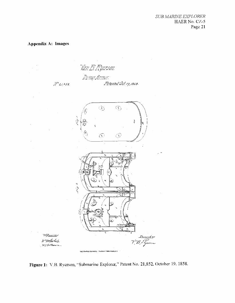
Kroehl's design incorporated features of an earlier diving bell, named Submarine Explorer that had been invented by Van Buren Ryerson and patented as Patent 21,582 on October 19, 1858. Ryerson's cylindrical craft consisted of a double-walled chamber containing compressed air that was heavily ballasted on the bottom. It was suspended from a vessel on the surface and could rise and submerge. The vessel could also sustain the life and operations of its crew without an air link to the surface. (See Appendix A, Figure 1.) Kroehl's innovations included lengthening the Ryerson cylinder into a boat-shaped craft, developing a more complex system of ballasting, and adding a propulsion system. Dived to depth as a sealed chamber and then pressurized to ambient sea pressure at depth, Kroehl's craft was then capable of direct access to the seabed through bottom hatches. This made Kroehl's Explorer a very different craft, termed an "automobile diving bell" or, in modern terms, a submersible with lock-out dive capability. While it was not the first such craft, with early examples dating to the 1850s (particularly the work of Lodner Phillips in the United States, Prosper Payerne in France, and Bruno de Villeroi in France), Kroehl's Explorer is, along with the contemporary American submersible Intelligent
1 The watch tower is the sole survivor of the type. Consequently, it is now a New York City Landmark and is listed in the National Register of Historic Places. For additional information, see Historic American Engineering Record, National Park Service, Department of the Interior, "Harlem Fire Watch Tower," HAERNo. NY-104. 2 For complete information on Kroehl, see the forthcoming publication by James Delgado entitled Sub Marine Explorer: the Historical and Archaeological Context of a Long-Lost Civil War Submarine and its Builders.
SUB MARINE EXPLORER HAERNo. CZ-5
Page 4
Whale, one of only two such "diver-lock out" craft of this pioneer period. Sub Marine Explorer is one of only five submarines dating to pre-1870 known to exist either as a display or as an archaeological site in the world as of 2007 when the fieldwork and research of this vessel was undertaken. The others are Wilhelm Bauer's Der Brandtaucher dating to 1850 in Kiel, Germany; an unnamed Confederate submarine dating to ca. 1862 in New Orleans, Louisiana; the Confederate submarine H.L. Hunley dating to 1863 in Charleston, South Carolina; and Intelligent Whale dating to 1866 in New Jersey.
Building Explorer required not only access to an industrial facility, such as Patterson's yard, but also it probably would have required a working partnership with Ariel Patterson for its design and fabrication. Kroehl, trained as an engineer with experience in iron casting and fabrication, was not a naval architect or shipbuilder. Patterson, a veteran New York shipbuilder, operated New York's fourth largest shipyard, Perrine, Patterson & Stack, between 1845 and 1853. The yard built a number of merchant vessels, clipper ships, and steamships, including several vessels employed in the steamer routes to and from Panama during the California Gold Rush. In one 1852 project, the yard built the experimental "caloric ship" Ericsson for inventor John Ericsson, which utilized hot air engines for propulsion. Perrine, Patterson & Stack dissolved in 1853, and the principals operated separately until 1854, when the shipbuilding boom collapsed. Patterson's last vessel, a 209-ton schooner, was launched in August 1854. Patterson remained at the site of the old Patterson, Perrine & Stack shipyard, at First Street near North Sixth, through 1865. City directories list him as a "shipbuilder" or "ship joiner" (carpenter) in 1861-62, and, when working with Kroehl, again as a "ship builder" from 1864-65. An advertisement in the Brooklyn directory at the time stated Patterson served as a "ship builder and ship smith" and noted his work in both wood and iron: "planning [sic], sawing, re-sawing, and scroll sawing," as well as "heavy iron planning [sic], turning, punching, and cutting."
Patterson's work with Kroehl probably involved his facilities as well as his shipbuilder's experience as the submersible progressed through design and into fabrication. The vessel's lines, metacentric height, stability, and trim required naval architectural experience, and certain construction features on the submersible, as noted archaeologically, suggest experienced marine engineering craftsmen were employed. For example, the bracing of the compressed air chamber (see below) employed what appear to be modified stays or braces from a marine steam boiler.
The construction sequence would have first required the completion of the initial drawings for every aspect of the submersible, and the laying out of the vessel's mould lines and preliminary offsets at Patterson's yard. The complex castings for the submersible required the completion of wooden patterns for each, based on the drawings, which would have likely been completed in Patterson's carpenter shop. The large wooden flasks, with their two-sided drag (or bottom), and cope (or top), contained the sand, clay, and water moldable composite that held the impression of the wooden pattern. Assembled and drilled with a riser and sprue to hold and pour the molten iron into the empty cavity, the cope was ready for casting. Iron melted on site at a casting shed
3 J. Lain, compiler, Lain's Brooklyn City Directory (Brooklyn: J. Lain, 1864), 368; J. Lain, compiler, Lain's Brooklyn City Directory (Brooklyn: J. Lain, 1865), 96.
SUB MARINE EXPLORER HAERNo. CZ-5
Page 5
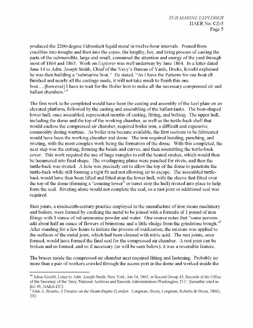
produced the 2200-degree Fahrenheit liquid metal in twelve-hour intervals. Poured from crucibles into troughs and then into the copes, the lengthy, hot, and tiring process of casting the parts of the submersible, large and small, consumed the attention and energy of the yard through most of 1864 and 1865. Work on Explorer was well underway by June 1864. In a letter dated June 14 to Adm. Joseph Smith, Chief of the Navy's Bureau of Yards, Docks, Kroehl explained he was then building a "submarine boat." He stated, "As I have the Patterns for one boat all finished and nearly all the castings made, it will not take much to finish this one boat.... [however] I have to wait for the Boiler Iron to make all the necessary compressed air and ballast chambers."
The first work to be completed would have been the casting and assembly of the keel plate on an elevated platform, followed by the casting and assembling of the ballast tanks. The boat-shaped lower hull, once assembled, represented months of casting, fitting, and bolting. The upper hull, including the dome and the top of the working chamber, as well as the turtle-back shell that would enclose the compressed air chamber, required boiler iron, a difficult and expensive commodity during wartime. As boiler iron became available, the first sections to be fabricated would have been the working chamber and dome. The iron required bending, punching, and riveting, with the most complex work being the formation of the dome. With this completed, the next step was the cutting, forming the bends and curves, and then assembling the turtle-back cover. This work required the use of huge mangles to roll the heated strakes, which would then be hammered into final shape. The overlapping plates were punched for rivets, and then the turtle-back was riveted. A hole was precisely cut to allow the top of the dome to penetrate the turtle-back while still forming a tight fit and not allowing air to escape. The assembled turtle- back would have then been lifted and fitted atop the lower hull, with the sleeve that fitted over the top of the dome (forming a "conning tower" or turret atop the hull) riveted into place to help form the seal. Riveting alone would not complete the seal, so a rust joint or additional seal was required.
Rust joints, a nineteenth-century practice employed in the manufacture of iron steam machinery and boilers, were formed by caulking the metal to be joined with a formula of 1 pound of iron filings with 1 ounce of sal-ammoniac powder and water. One source notes that "some persons add about half an ounce of flowers of brimstone and a little sludge from the grindstone trough." After standing for a few hours to initiate the process of oxidization, the mixture was applied to the surfaces of the metal joint, which had been cleaned with nitric acid. The rust joints, once formed, would have formed the final seal for the compressed air chamber. A rust joint can be broken and re-formed, and so if necessary (as will be seen below), it was a reversible feature.
The braces inside the compressed air chamber next required fitting and fastening. Probably no more than a pair of workers crawled through the access port in the dome and worked inside the
44 Julius Kroehl, Letter to Adm. Joseph Smith, New York, Jun 14, 1865, in Record Group 45, Records of the Office of the Secretary of the Navy, National Archives and Records Administration-Washington, D.C. (hereafter cited as RG 45, NARA-DC). 5 John A. Bourne, A Treatise on the Steam-Engine (London: Longman, Green, Longman, Roberts & Green, 1866), 292.
SUB MARINE EXPLORER HAERNo. CZ-5
Page 6
compressed air chamber, hand-fastening the braces one at a time, before bolting the top and then the bottom to the angle-iron ribs and angle-iron mounts. With the turtle-back firmly bolted into place, the external portions of Explorer were completed. Either at this time, or perhaps earlier, workers would begin installing the internal systems, which included fitting the propulsion machinery and installing the piping systems for transferring compressed air into the working chamber and ballast chambers, as well as the dive manifold for regulating the egress of air from the ballast chambers as they filled with seawater. The hatches on the bottom of the submersible may have provided easier access and working conditions on an elevated platform than access through the dome.
Once the internal systems were fitted, the final details would have included fitting the propeller, rudder, and steering system, and final painting of the interior and possibly the exterior of the submarine. The interior was probably painted white to reflect the light of the spermaceti candles Kroehl employed. The exterior may not have been painted because of the rust joint. As one source states, "the skin of the iron must, in all cases, be broken where a rust joint is to be made; and, if the place be greasy, the surface must be well rubbed over with nitric acid, and then washed with water, till no grease remains. The oil about engines has a tendency to damage rust joints by recovering the oxide." Explorer's, case is different than rust joints for engines, but this shows the relationship between oxide and oil, and most paints of the period were oil-based. If the exterior were painted, the rust joint would have been avoided.
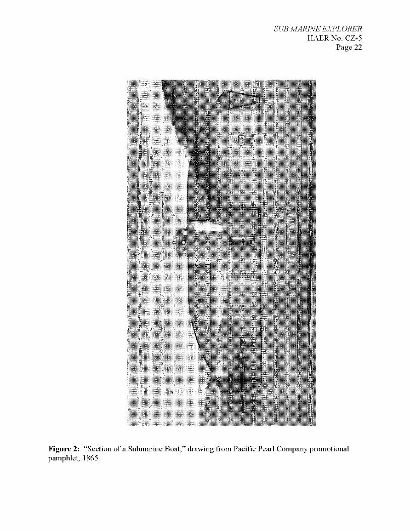
Other final details would have included fitting the rubber gaskets for the hatches and manhole and fitting and installing the glass deadlights in the dome collar sleeve (turret) and bow. (See Appendix A, Figure 2 for a drawing of Sub Marine Explorer.) The construction crew would have transferred Explorer, probably by the yard's marine railway, to the dock at the foot of North Third and launched her into the East River, sometime around or after the reported completion of the submersible in November 1865. Given winter conditions and the probability of ice in the river, it is likely that the launching took place in spring 1866. The first of four trials took place over a short period of time, culminating in the fourth "private trial" in front of the Pacific Pearl Company's officers and investors on May 30, 1866.
Operation Intended for military purposes, as well as commercial operation in the Pacific as a pearl-diving craft, Kroehl's Sub Marine Explorer was funded by a consortium of investors who incorporated as the Pacific Pearl Company with a capital stock of $1,000,000 in 1865. They reportedly paid $40,000 for the vessel's construction. As stated in one publication,
THIS Company has been organized for the purpose of gathering pearls and pearl- shells on the Pacific coast. Their operations will be carried on by means of a Sub- Marine Explorer of an improved construction. The enterprise is not speculative, but as real, substantial, and legitimate, as the smelting of copper or the importation of ivory. It was suggested by the progress and inventions of the arts,
Bourne, 292.
SUB MARINE EXPLORER HAERNo. CZ-5
Page 7
and the caprices of fashion, which have made pearls and pearl-shells, or mother- of-pearl, essential among articles of luxury. The largely increased and increasing demand for these articles has prompted men of genius and enterprise to perfect some mode of gratifying this demand, more reliable than the uncertain and dangerous process of searching for them by divers.
Following the tests and the decision to relocate Explorer to Panama, the yard partially disassembled the submersible so it could be shipped as cargo. This probably took a few months. The only portions of the craft readily accessible for disassembly without punching out rivets (an unlikely, expensive, and potentially damaging process) would have been the external plates sealing the ballast chambers, the rudder, propeller, and potentially the turtle-back, all of which, if removed and separately crated for shipment, would have reduced the total weight of the sub by one-third. A considerable amount of disassembly was apparently undertaken, as Explorer arrived in Panama in December, was shipped across the isthmus by flatcar by the Panama Railroad, and then was reassembled at the Panama Railroad dock in Panama City. The reassembly took until May 1867 when the first open water tests of the submarine occurred.
Isla San Telmo, where the open water tests took place, rests at the edge of a formerly rich series of pearl oyster beds that were known to the pre-European contact inhabitants of the islands. Heavy "fishing" in the early Spanish colonial period and again in the eighteenth and early nineteenth centuries successively depleted the beds. The "Pearl Islands" were a seemingly ideal location to operate the submarine and utilize its technological advantage for greater profit than the earlier techniques used by breath-holding divers. This turned out not to be case, though, because by the time Explorer arrived, the pearl beds had been effectively fished out, although this was not known to the Pacific Pearl Company at the time. Tests of the submersible continued through summer 1867 but the expedition abruptly ended with the death of Kroehl in September, probably due to a recurrence of his malaria, after which it sat idle. A new supervising engineer took charge of the craft, and pearl diving commenced again in the Pearl Islands from 1868 to 1869. The last known dives, in November 1869, ended with the submersible's lay-up in a small cove off Isla San Telmo. No further contemporary mention of the craft was made. The dives ceased after Explorer's crew came down with fevers that were attributed to the tropical locale at the time but were probably the result of decompression sickness. Reports of the operation of the submarine indicate that the crew did not decompress properly, leading to the cessation of the dives. The company's decision to fish an area that had been depleted coupled with the technological failure of the submarine and crew to decompress properly led to the abandonment of the vessel. Pacific Pearl Company attempted to patent Explorer but the application was never completed for unknown reasons. In 1870, the Pacific Pearl Company was listed in the New York City directory, but it disappeared after that date. In 1924, the company was dissolved.
Reports of a mysterious submarine thought to date to World War II and to be of Japanese origin began to circulate in the 1960s. Inhabitants ofthe islands, descendents of slaves imported for the
7 The Pacific Pearl Company, Incorporated Under the Laws ofthe State of New York (New York: Published by E. S. Dodge & Co., printers and stationers, 84 John Street, 1865), 3.
SUB MARINE EXPLORER HAERNo. CZ-5
Page 8
pearl fishery, were vague about the craft's origins. At some time in the past, unknown parties appear to have partially blasted into the submarine to salvage it. Extensive damage to the stern is suggestive of blasting to gain access to the submersible's presumably brass propulsion machinery. Wire cable is wrapped around the "conning tower" or turret, and strain on that wire deformed the hull in this area. The manhole, or hatch, atop the submersible was cut off, either by chisel or torch, and the rudder and propeller were also removed. Most of the accessible brass, bronze, or copper fittings were stripped, including much of the interior piping, although the brass manifold remains.
DESCRIPTION In addition to the detailed archaeological and architectural assessments of Sub Marine Explorer undertaken in the field between 2001 and 2008, two of the primary sources of information on the vessel's appearance and operation are a drawing of the submarine by Julius Kroehl and a report by W.W.W. Wood, General Inspector of Steam Machinery with the U.S. Navy. The U.S. Navy had assigned Wood to inspect and evaluate the submarine, which resulted in an eighteen-page report dated February 2, 1865. Kroehl's drawing is ink on linen, and it was likely produced especially to give to Wood when his report was presented to the U.S. Navy. The sheet is composed of a longitudinal section, half plan, and partial cross-section and is well detailed at 3/i" to the foot scale. In addition to showing proposed construction methods, it could also be considered a general arrangement drawing. The name of the draftsman is not given, but the signature by Kroehl indicates that he may have produced it himself. Kroehl would have had many other drawings to build his complicated vessel from, but, as is usual with commercial endeavors, these records were apparently not saved and no other drawings of Explorer have been found. Thus, it is because of the federal government's interest in this project that Kroehl's drawing and Wood's report has survived. Wood's report was presented to the U.S. Navy to demonstrate the viability of employing such a vessel for quasi-military purposes. It is therefore a very detailed and comprehensive document that explains all aspects of the proposed vessel's construction and speculates on its then unproved merits.
Body Julius Kroehl designed Sub Marine Explorer with three distinct spaces: the water ballast chambers, the compressed air chamber, and the working chamber with its central dome. The vessel is 36' long, 10' in breadth, and 10'-6 V2" in overall height. For the most part, the lower section (to a line 4' above the underside of the bottom plate) is of cast iron that is bolted or screwed together. In form, it resembles a bateau, a double-ended, flat-bottomed craft with raking bow and stern and flaring sides. Above the 4' line, riveted wrought iron (which Kroehl described as boiler iron) is mostly employed. This top can be described as "turtle-backed" in form. The dome and the top lining of the working chamber are also wrought iron.
Kroehl's drawings show that he assigned station lines to his vessel at 2' intervals, beginning with "0" at the foremast tip of the bow, termed the fore perpendicular, and ending at the stern with "36," termed the aft perpendicular.
SUB MARINE EXPLORER HAERNo. CZ-5
Page 9
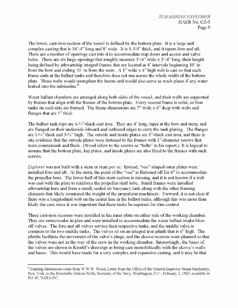
The lower, cast-iron section of the vessel is defined by the bottom plate. It is a large and complex casting that is 34'-4" long and 8' wide. It is 1-3/4" thick, and it tapers fore and aft. There are a number of openings cast into it to accommodate trap doors and access and valve holes. There are six large openings that roughly measure 3'-6" wide x 3'-4" long, their length being defined by athwartship integral frames that are located at 4' intervals beginning 10' in from the bow and ending 10' in from the stern. A 1" wide x 4" high web is cast so that each frame ends at the ballast tanks and therefore does not run across the whole width of the bottom plate. These webs would strengthen the beams and would also serve as wash plates if any water leaked into the submarine.
Water ballast chambers are arranged along both sides of the vessel, and their walls are supported by frames that align with the frames of the bottom plate. Every second frame is solid, so four tanks on each side are formed. The frame dimensions are 7" wide x 4" deep with webs and flanges that are 1" thick.
The ballast tank tops are l-W-thick cast iron. They are 4' long, taper at the bow and stern, and are flanged on their underside inboard and outboard edges to carry the tank plating. The flanges are l-3/i" thick and 3-3/4" high. The outside and inside plates are l"-thick cast iron, and there is site evidence that the outside plates were fastened to the frames with l"-diameter screws that were countersunk and flush. (Wood refers to the screws as "bolts" in his report.) It is logical to assume that the bottom plate, top plates, and inside plates are also fixed to the frames with such screws.
Explorer was not built with a stern or stem/?er se. Instead, "vee" shaped outer plates were installed fore and aft. At the stern, the point of the "vee" is flattened off for 6" to accommodate the propeller boss. The lower half of this stern section is missing, and it is not known if a web was cast with the plate to reinforce the propeller shaft tube. Small frames were installed athwartship here and form a small, sealed air buoyancy tank along with the other framing elements that likely countered the weight of the propulsion machinery. Forward, it is not clear if there was a longitudinal web on the center line in the ballast tanks, although this was more than likely the case since it was important that these tanks be separate for trim control.
Three cast-iron recesses were installed in the inner plate on either side of the working chamber. They are semicircular in plan and were installed to accommodate the water ballast intake/blow off valves. The fore and aft valves service their respective tanks, and the middle valve is common to the two middle tanks. The valves sit on an integral iron plinth that is 6" high. The plinths facilitate the movement of the valve's plugs, and the alcove recesses were planned so that the valves were not in the way of the crew in the working chamber. Interestingly, the bases of the valves are shown in Kroehl's drawings as being cast monolithic ally with the alcove's walls and bases. This would have made for a very complex and expensive casting, and it may be that
8 Framing dimensions come from W.W.W. Wood, Letter from the Office of the General Inspector Steam Machinery, New York, to the Honorable Gideon Wells, Secretary of the Navy, Washington, D.C., February 2, 1865, available in RG 45, NARA-DC.
SUB MARINE EXPLORER HAERNo. CZ-5
Page 10
for ease of maintenance, they were cast separately. Excavation and analysis of the bottom of the submersible would provide the final answers to this question.
Each ballast tank has an 18"-diameter access hole and cover plate in its inside plate. The holes were for inspection, maintenance, and removal of scale.
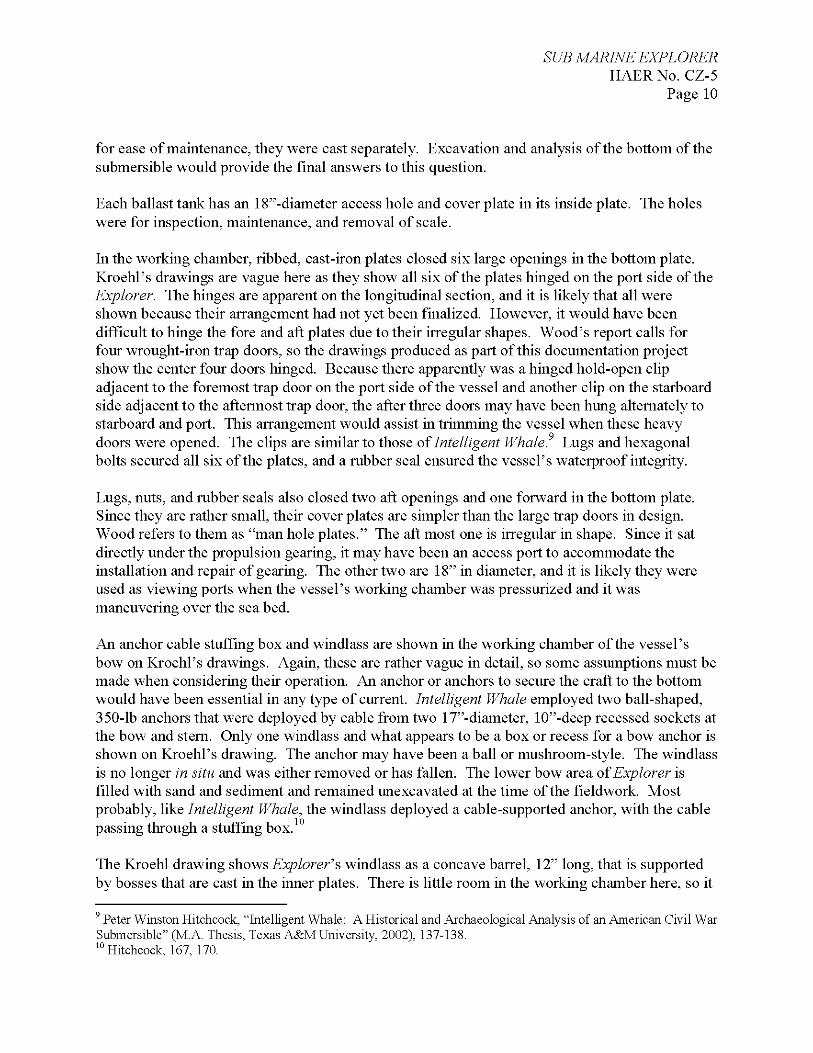
In the working chamber, ribbed, cast-iron plates closed six large openings in the bottom plate. Kroehl's drawings are vague here as they show all six of the plates hinged on the port side of the Explorer. The hinges are apparent on the longitudinal section, and it is likely that all were shown because their arrangement had not yet been finalized. However, it would have been difficult to hinge the fore and aft plates due to their irregular shapes. Wood's report calls for four wrought-iron trap doors, so the drawings produced as part of this documentation project show the center four doors hinged. Because there apparently was a hinged hold-open clip adjacent to the foremost trap door on the port side of the vessel and another clip on the starboard side adjacent to the aftermost trap door, the after three doors may have been hung alternately to starboard and port. This arrangement would assist in trimming the vessel when these heavy doors were opened. The clips are similar to those of Intelligent Whale. Lugs and hexagonal bolts secured all six of the plates, and a rubber seal ensured the vessel's waterproof integrity.
Lugs, nuts, and rubber seals also closed two aft openings and one forward in the bottom plate. Since they are rather small, their cover plates are simpler than the large trap doors in design. Wood refers to them as "man hole plates." The aft most one is irregular in shape. Since it sat directly under the propulsion gearing, it may have been an access port to accommodate the installation and repair of gearing. The other two are 18" in diameter, and it is likely they were used as viewing ports when the vessel's working chamber was pressurized and it was maneuvering over the sea bed.
An anchor cable stuffing box and windlass are shown in the working chamber of the vessel's bow on Kroehl's drawings. Again, these are rather vague in detail, so some assumptions must be made when considering their operation. An anchor or anchors to secure the craft to the bottom would have been essential in any type of current. Intelligent Whale employed two ball-shaped, 350-lb anchors that were deployed by cable from two 17"-diameter, 10"-deep recessed sockets at the bow and stern. Only one windlass and what appears to be a box or recess for a bow anchor is shown on Kroehl's drawing. The anchor may have been a ball or mushroom-style. The windlass is no longer in situ and was either removed or has fallen. The lower bow area of Explorer is filled with sand and sediment and remained unexcavated at the time of the fieldwork Most probably, like Intelligent Whale, the windlass deployed a cable-supported anchor, with the cable passing through a stuffing box.
The Kroehl drawing shows Explorer's windlass as a concave barrel, 12" long, that is supported by bosses that are cast in the inner plates. There is little room in the working chamber here, so it
9 Peter Winston Hitchcock, "Intelligent Whale: A Historical and Archaeological Analysis of an American Civil War Submersible" (MA. Thesis, Texas A&M University, 2002), 137-138. 10 Hitchcock, 167, 170.
SUB MARINE EXPLORER HAERNo. CZ-5
Page 11
would have been operated by only one man who would have used an iron bar for leverage. It is likely that a ratchet regulated the windlass. When the anchor was hove to the hull, the cable probably simply remained wrapped around the capstan barrel.
Generally speaking, the bottom section of Explorer seems very sound and almost over-designed. This is due to natural uncertainties over design requirements in a fledgling field of engineering. "Overbuilding" is a design feature noted by archaeological and architectural historians with many mid-nineteenth-century iron structures. The over-designed nature of Explorer would also have made it expensive to build. Many of the castings are very complex and even though the vessel is quadrally symmetrical, only a few of the mold patterns could have been used for more than two applications. Further, waterproof integrity relied on rust joints and this technique demanded extremely tight fitting surfaces, so much hand fitting and grinding would have been necessary. This may help account for the reported cost, in 1865, of $40,000 for Explorer, which in 2007 would be slightly more than half a million dollars.
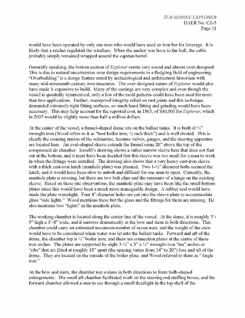
At the center of the vessel, a funnel-shaped dome sits on the ballast tanks. It is built of V2" wrought iron (Wood refers to it as "best boiler iron, V2 inch thick") and is well riveted. This is clearly the conning station of the submarine, because valves, gauges, and the steering apparatus are located here. An oval-shaped sleeve extends the funnel some 20" above the top of the compressed air chamber. Kroehl's drawing shows a rather narrow sleeve here that does not flair out at the bottom, and it must have been decided that this sleeve was too small for a man to work in when the fittings were installed. The drawing also shows that a very heavy cast-iron sleeve with a thick cast-iron hatch (manhole plate) was planned. Two I-V2" diameter bolts secured the hatch, and it would have been slow to unbolt and difficult for one man to open. Currently, the manhole plate is missing, but there are two bolt clips and the remnants of a hinge on the existing sleeve. Based on these site observations, the manhole plate may have been like the small bottom plates since this would have been a much more manageable design. A rubber seal would have made the plate watertight. Four 4"-diameter holes are cut into the sleeve plate to accommodate glass "side lights." Wood mentions these but the glass and the fittings for them are missing. He also mentions two "lights" in the manhole plate.
The working chamber is located along the center line of the vessel. At the dome, it is roughly 5'- 9" high x 3'-8" wide, and it narrows dramatically at the bow and stern in both directions. This chamber could carry an estimated maximum number of seven men, and the weight of the crew would have to be considered when water was let into the ballast tanks. Forward and aft of the dome, the chamber top is V2" boiler iron, and there are connection plates at the centre of these iron arches. The plates are supported by eight 3-Vi" x 3" x V2" wrought-iron "tee" arches or "ribs" that are fitted at roughly 18" apart (the spacing varies from 14" to 20") fore and aft of the dome. They are located on the outside of the boiler plate, and Wood referred to them as "Angle iron."
At the bow and stern, the chamber top widens in both directions to form bulb-shaped enlargements. The small aft chamber facilitated work on the steering rod stuffing boxes, and the forward chamber allowed a man to see through a small deadlight in the top shell of the
SUB MARINE EXPLORER HAERNo. CZ-5
Page 12
compressed air chamber. Again, this light is missing, but there is a large hole in the vessel where it was fitted, and Kroehl's drawing also shows it. This light would have been similar to those in the dome sleeve.
Curiously, Kroehl had planned to fit partitions on Explorer at the extreme ends of the working chamber. These seem to be watertight bulkheads with small doors measuring 1 '-9" wide x 3' high in them. They are shown on his drawing l'-6" inboard of the windlass and l'-4" inboard of the propulsion wheel. It is impossible to guess what the purpose of these bulkheads might be given the extreme lack of space here, but it seems the idea was abandoned because no trace of them can be found aboard the submersible.
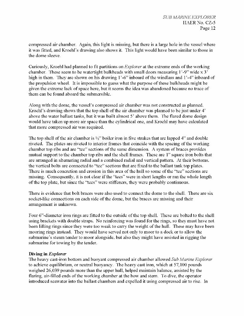
Along with the dome, the vessel's compressed air chamber was not constructed as planned. Kroehl's drawing shows that the top shell of the air chamber was planned to be just under 4' above the water ballast tanks, but it was built almost 5' above them. The flared dome design would have taken up more air space than the cylindrical one, and Kroehl may have calculated that more compressed air was required.
The top shell of the air chamber is V2" boiler iron in five strakes that are lapped 4" and double riveted. The plates are riveted to interior frames that coincide with the spacing of the working chamber top ribs and are "tee" sections of the same dimension. A system of braces provides mutual support to the chamber top ribs and the shell frames. These are 1" square iron bolts that are arranged in alternating radial and a combined radial and vertical pattern. At their bottoms, the vertical bolts are connected to "tee" sections that are fixed to the ballast tank top plates. There is much concretion and erosion in this area of the hull so some of the "tee" sections are missing. Consequently, it is not clear if the "tees" were in short lengths or ran the whole length of the top plate, but since the "tees" were stiffeners, they were probably continuous.
There is evidence that bolt braces were also used to connect the dome to the shell. There are six socket-like connections on each side of the dome, but the braces are missing and their arrangement is unknown.
Four 6"-diameter iron rings are fitted to the outside of the top shell. These are bolted to the shell using brackets with double straps. No reinforcing was found for the rings, so they must have not been lifting rings since they were too weak to carry the weight of the hull. These may have been mooring rings instead. They would have served not only to moor to a dock or to allow the submarine's steam tender to moor alongside, but also they might have assisted in rigging the submarine for towing by the tender.
Diving in Explorer The heavy cast-iron bottom and buoyant compressed air chamber allowed Sub Marine Explorer to achieve equilibrium, or neutral buoyancy. The heavy cast iron, which at 57,100 pounds weighed 26,039 pounds more than the upper hull, helped maintain balance, assisted by the flaring, air-filled ends of the working chamber at the bow and stern. To dive, the operator introduced seawater into the ballast chambers and expelled it using compressed air to rise. In

SUB MARINE EXPLORER HAERNo. CZ-5
Page 13
1865, W.W.W. Wood described how the submarine had "ease of descent and ascent." To dive, the operator opened the blow off cocks in the ballast or water chambers "to admit water. The specific gravity of the boat is thus increased at will, and the descent may be made rapid or slow as desired by the operator, it is thus perfectly competent to descend to final limit or remain suspended at intermediate depth required."
To ascend,
the blow off cocks would be closed, the exhaust valve of the water chamber opened and air from the compressed air chamber admitted; this being at greater pressure than the water forces it out; and thus reducing the specific gravity causes the boat to rise at the will of the operator governed by the force with which the air is admitted into, and the water forced out of, the water chambers. These two chambers (compressed air and water chambers) thus perform for the boat the same office that the air bladder does for the fish, and at once does away with all necessity for suspended ballast or any other extraneous methods of sinking the vessel. The division of the water chambers into fore, aft, and amid-ship chambers, allows the perfect equilibrium of the boat to be maintained without the
1 o
necessity of shifting ballast.
Wood's report stated the three chambers enclosed a total area of 1,770 cubic feet. They were divided as follows: compressed air chamber-560 cubic feet (15.8 cubic m); ballast chambers-550 cubic feet (15.5 cubic m); working chamber-600 cubic feet (18.6 cubic m).
According to a published account of an 1869 dive in the submarine, the compressed air chamber was pressurized to 60 pounds per square inch. The vessel was then sealed, and the crew began the dive by flooding the ballast chambers. Since each cubic foot of seawater weighs 64 pounds, completely flooding the ballast tanks would have added 35,200 pounds of weight (or 4,241 gallons of seawater) to overcome the buoyant force of the 1,220 cubic feet of the air-filled chambers. To submerge, Explorer needed to displace 116,745 pounds. The submarine's weight was 88,161 pounds, so it needed to add approximately 28,584 pounds, or 3,443.8 gallons of seawater, to submerge.
Propulsion and Steering It would seem that Kroehl considered two steering techniques before deciding on the one that he would finally employ on Explorer. The first appears in the Pacific Pearl Company pamphlet and had no rudder proper. Instead, the propeller sat on an iron frame hung on hinges at the vessel's stern. Just outboard of the stern a universal joint connected the propeller to the shaft. Wood calls this "Cathcart's plan," referring to the system of yoking a rudder and propeller together with a universal joint as patented by James L. Cathcart of Washington, DC, in 1854, and
11 "Apparatus for Submarine Exploration," Provisional Patent No. 2466, August 29, 1867, 15. 'Apparatus for Submarine Exploration," 15.
SUB MARINE EXPLORER HAERNo. CZ-5
Page 14
subsequently refined through the 1860s. The Buffalo [New York] Commercial Advertiser of Wednesday, August 16, 1871, described the system.
The CATHCART was built in Washington, D.C., in 1869, and has been running for a length of time on the Schuykill Canal, where she is said to have been quite successful. She is 98 feet over all, 17 lA feet wide, 8 lA feet hold and registers 93 63-100 tons. Her carrying capacity, exclusive of fuel and water, is 175 tons.. .The propelling power is a common screw wheel in her stern. The most interesting feature of the CATHCART's machinery is the steering apparatus, which worked admirably. The improvement consists of a moveable joint on the shaft of the propeller, outside of the sternpost of the boat, by which the propeller can be moved laterally by a standard coming up like the rudder head to the deck of the boat. On this is fitted a semi-circular yoke about five feet long, to each end of which is a chain fastened, the bugles passing round a wheel about a foot in diameter, which is fastened to the rudder head, and fitted with cogs to catch the links of the chain. Thus the direction of the rudder and propeller are changed simultaneously, at the will of the helmsman. When going straight ahead, the direction of the rudder and the wheel are on a line with the keel. But as the rudder is moved, the pressure of the wheel is shifted to the quarter, making the propeller power an aid to the rudder in steering the boat. With this arrangement a very slight deflection of the rudder produces a considerable change in the direction of the boat. It is claimed that the CATHCART steers easily in water only a few inches deeper than her draught. On leaving one of our elevators, loaded, she turned around in a space a little more than her own length, which is sufficient evidence of her good steering qualities.
The New York World of July 22, 1871, had earlier commented on the Cathcart system.
Mr. J.S. Cathcart, which has been tried on the propeller CATHCART, and which is claimed to be an entire success. The improvement is a movable joint on the shaft of the propeller, outside of the stern-post of the boat, by which the propeller can be moved laterally by a standard coming up like the rudder-head to the deck of the boat. On this is fitted a semi-circular yoke about five feet long, to each end of which is a chain fastened, the bugles passing round a wheel about a foot in diameter, which chain. Thus each motion of the rudder alters the direction of the propeller with the helm amidships; the pressure of the propeller is in the line of the keel of the boat, or directly aft as in ordinary boats, but as the rudder is moved the pressure is shifted to the quarter, thus making the propeller an aid to the rudder in steering the boat, and requiring so slight a deflection of the direction of the rudder that little or no swell is caused thereby. And this is the advantage claimed, that the boat will run without any wash to injure the banks of the canal, and will steer easily even when there is little more water in the canal than the boat draws.
SUB MARINE EXPLORER HAERNo. CZ-5
Page 15
Presumably Kroehl's use of the Cathcart system, which is illustrated in a redrawn plan in an 1865 pamphlet of the Pacific Pearl Company, was abandoned because it was impractical. Due to the universal joint, a good deal of power would have to be exerted on the propeller as its angle became more acute. With a hand-powered device operated presumably by one man inside a sealed compartment, this would not have provided the same power as a steam engine. In addition, the cramped internal area of the submersible did not provide adequate room for the Cathcart apparatus as well as the propulsion system's machinery. The second method appears on Kroehl's drawing and shows the rudder held aft of the propeller by carriers at the top and bottom. The forward ends of the carriers were to be hinged within the vessel. This may not have been used because the connections would have been difficult to waterproof.
Explorer's rudder, propeller, propulsion, and steering machinery, and a large section of the lower part of her stern are missing as a result of explosive demolition to salvage the machinery. However, there is an iron plate bolted to the top of the aft ballast tank and what seems to be a carrier (it is broken off) pierces the top shell. From this, it may be concluded that a more conventional rudder was installed with carriers top and bottom. A cable system controlled the rudder; a yoke was fixed to the top of the rudder and cable linkages were attached to both of its ends. Two steering rods that passed through cast-iron tubes set into the top shell were at the inboard ends of the linkages. Stuffing boxes were fitted here, and the inner ends of the rods connected to inboard cables. The cable was likely a flexible wire of Vi" diameter, and there were pulley-like fixed guide blocks at the sides of the working chamber leading to the vessel's dome. This is similar to the system employed on Intelligent Whale. No evidence was found of controlling devices for the cables, but lockable levers or slide blocks are assumed to have been used. A wheel at the control station steered Intelligent Whale, but such a system would have proved cumbersome in Explorer due to the need to freely pass and work in the cramped quarters of the submarine.
Kroehl's drawing shows a 3 '-6"-diameter propeller and this is confirmed in Wood's report. From the drawings, it seems to be four-bladed, although at the time two- or three-bladed propellers were more common. It also seems to have turned in a counter-clockwise direction, when seen from aft, to move the vessel forward. The shaft and gear mechanism is best understood when looking at drawings, but it is not complicated. Three shafts with four gears were carried on bridges with pillow blocks that could be lubricated. A heavy iron turning wheel that, due to the cramped space in the working chamber, could have been moved by only one man operated the machinery. The small gears are about 10" in diameter (31.43" in circumference), while the large ones are I8-V2" in diameter (58.14" in circumference). This gives a speed advantage of about 185 percent per gearing, and there are three gearings. Thus, if the turning wheel was spun at 30 revolutions per minute, the propeller would turn at 190 revolutions per minute. While not shown on the drawings, a detachable iron crank may have been part of the mechanism to facilitate the rotation of the wheel by an operator.
Hitchcock, 161.
SUB MARINE EXPLORER HAERNo. CZ-5
Page 16
When looking at the propulsion machinery, it is difficult to imagine how one man could push such a heavy weight as Explorer through the water. However, once set into motion, the heavy turning wheel would act at least as a minimal fly wheel. While Wood states in his report that the apparatus had not been tested and that he could not provide an opinion, he also stated, "the means provided for locomotion would seem ample to secure a rate of speed sufficient to overcome local currents."
Piping Unfortunately, most of Explorer's piping systems are missing. According to Wood, they did not appear on Kroehl's drawings because "their position will be decided when the boat is nearly finished." Wood reveals what was intended for the vessel, but from archaeological observations, it seems that some changes were made. Much of the piping appears to have been copper and brass and was stripped from the submersible at some point after abandonment. Fragments and indications of differential corrosion on the interior of the submersible reveal probable placement of some piping.
A 30-hp air pump of "7 lA in diameter driven by a direct acting engine of 14 in diameter, both air pump and steam cylinder having an 18 in stroke" pumped air into the compressed air chamber. A tender carried the machinery, and Wood states that the air pressure chamber was tested at 200 pounds per square inch (psi). Just ahead of the dome, there is a l"-diameter threaded hole in the top shell that is assumed to be the compressed air supply. This would connect to the air pump with a hose. In the lower dome there is a ere scent-shaped pipe that has a valve at its bottom end and a flanged "tee" in the middle that may have been a pressure gauge. Both ends of this pipe discharge into the compressed air chamber. A pipe is assumed to have connected to the hole in the shell with a valve and lead to the top of the crescent pipe. The lower end of the crescent simply discharged air into the chamber; the vessel's operator controlled it by the valve while using the gauge.
There are a number of similar flanges in four key positions on Explorer. They are located where the middle tanks join the fore and aft tanks and can be considered as control positions. At each location, two flanges are fit to the top of the ballast tanks. They are about 25" apart, centered on the tank's joint, and the pipe size seems to be about I-V2" inside diameter. Two similar flanges are fitted directly above them and connect to the air pressure chamber. Thus, a pipe with a control valve connected the air pressure chamber to the water ballast chamber. Wood notes that a 3/4" valve admitted air into the working chamber, and while no evidence of this has been found, it may be assumed that the working chamber drew air from the compressed air chamber.
After both air spaces had been pressurized, the vessel was submerged by opening the six ballast fill and blow off valves, probably in a prescribed sequence, until it began to sink. The valves would then be closed. To surface, the valves connecting the ballast tanks to the compressed air chamber were opened, again probably in a sequence, and their corresponding blow off valves
14 "Apparatus for Submarine Exploration," 5. 15 "Apparatus for Submarine Exploration," 5. 16 "Apparatus for Submarine Exploration," 4.
SUB MARINE EXPLORER HAERNo. CZ-5
Page 17
would be opened. In the top of the center blow off valve alcoves, there seems to be a pipe valve that connects the two central tanks. Its design and function are not known. Even through the center blow off valves serviced both middle tanks, this pipe valve may have been a water and air transfer valve.
A 2"-outside diameter pipe connects to the atmosphere at the aft end of the dome sleeve and leads down into the dome. At its bottom end is a valve and a cluster of flanges for a l-Vi" outside diameter pipe. At the top of the ballast tanks, between the four sets of compressed air transfer valves, 3/i" pipes lead to a connection tube that extends upward (the only surviving example in the submarine is heavily concreted). In an experiment, the authors of this report connected the dome valves to the upstand pipe with l-Vi" outside diameter pipe in a logical manner. This experiment led to the conclusion that this configuration forms a compressed air exhaust system to expel air from the ballast tanks. Wood mentions air exhaust, but the reference is ambiguous. The provisional patent notes, "a pipe is also disposed at the top of the casing passing through the roof for discharging air at any time from the working chamber when it is desired to reduce the buoyant power of the apparatus."
Connected to the bottom plate in the dome area is a brass sleeve with a glass tube inside that has been broken off at about 12" and still contains mercury. This is assumed to be the remains of a depth gauge. It must be noted that on this submersible there was no means of regulating depth (depth in a more modern submarine is controlled by propulsion and planes). The submersible either sat on the surface or the bottom or went up and down. Furthermore, operating the valves was a delicate matter because a very small quantity of air or water, rather like the "last straw" near the end of blowing off or flooding, made the vessel sink or rise.
Having an indication of depth and water pressure was also critical to the lock-out function of the submarine. Knowing the ambient pressure at the bottom allowed the operator to let an equal amount of compressed air into the working chamber to the point that the internal pressure was the same as the external. A sea cock used as a "test cock" would be opened to allow water to flow into the chamber at a minimal volume, and as the pressure built up, the flow would stop, indicating equalization.
Air Replenishment and Internal Illumination Other than ambient light introduced to the submarine through the dome and bow headlights, Kroehl indicated the interior could be lit with candles. One account noted that spermaceti candles were employed. Spermaceti, a solid, waxy product taken from a cavity in the head of a Sperm Whale, was one of the by-products of the whaling industry. Like sperm oil, also in the
1 Q
head cavity, spermaceti burned clear and bright, and because of this was a valuable commodity. Candle makers mixed the spermaceti with 5 to 10 percent paraffin to make spermacetic candles, which at the time of Explorer's dives were considered the best candles as they were brighter and
17 "Apparatus for Submarine Exploration," 2. 18 Lance E. Davis, Robert E. Gallman, and Karen Gleiter, In Pursuit of Leviathan: Technology, Institutions, Productivity, and Profits in American Whaling, 1816-1906 (Chicago and London: University of Chicago Press, 1997), 29, 56, 344.
SUB MARINE EXPLORER HAERNo. CZ-5
Page 18
lasted longer than a pure wax candle. The standard measurement of light at the time, one candle power (cp) was measured as the light given off by a 2 ounce pure spermaceti candle that burned 120 grains per hour.
Maintaining an adequate oxygen level in a submerged craft was and remains a critical factor in determining a submarine or diving bell's success. Explorer had the means to replenish the air in the working chamber by introducing air stored in the compressed air tanks. However, the principal means was through spraying seawater in a fine mist throughout the chamber. The idea was to force the "carbonic acid gas" that accumulated inside the sub to be absorbed into the seawater, which would then release oxygen. Seawater for the air purification system was admitted through an "induction pipe extending down to the water and provided with a discharge pipe with a rose head." The only archeological evidence of this system was a handle and rod assembly with a plunger valve at the proximal end. Looking much like the central portion of a bicycle pump, this may be the remains of a portable "hand force" pump used to distribute seawater inside the working compartment by drawing water up to be discharged through a hose.
CONCLUSION The surviving plan, contemporary accounts, and the material record in the form of the remains of the Sub Marine Explorer are not sufficient by themselves as solitary evidence to reconstruct this unique, individual craft. However, the combination of all the evidence, as well as a "best guess" based on an understanding of the technology and materials of the time, plus comparison with the more intact Intelligent Whale, has allowed this fairly detailed reconstruction of the vessel.
Sub Marine Explorer is, as G. W. Baird noted in a 1903 article, a link between the diving bell and the submarine, borrowing the basic systems configuration for pressurization from Van Buren Ryerson's Explorer of 1858, but with fundamentally different aspects that make it a true
91 submarine, and more particularly, a submarine with a lock-out diver chamber. As Kroehl reported in a letter, his submarine did not need any
communication .. .with the surface so that the enemy will be unable to discover its movements below water as is the case with all other submarine boats. In other boats, the enemy can cut the necessary supply of air from the parties inside the boat, thereby endangering the lives of its occupants. It is independent of hose, float or anything connected with the surface of the water, & by a simple process of purifying the air when it has become vitiated by respiration it enables the men to remain for 24 hours or in fact an indefinite period of time.
19 Rudolf Wagner, A Handbook of Chemical Technology (London: J. & A. Churchill, 1872), 634. 20 'Apparatus for Submarine Exploration," 2. 21 G.W. Baird, "Submarine Torpedo Boats,'" Journal of the American Society of Naval Engineers 14, no. 2 (1902): 852. 22 George Wrightson to Gideon Welles, New York, June 14, 1864, Letters Sent to the Secretary of the Navy, RG 45, NARA-DC.

SUB MARINE EXPLORER HAERNo. CZ-5
Page 19
Despite the fact that this type of design was later abandoned, the submarine remains significant as one of only five known submarines dating to pre-1870 and an example of early submarine technology. The submarine was, and remains, even as a ruin, an amazing technological and engineering achievement of the mid-nineteenth century.
SUB MARINE EXPLORER HAERNo. CZ-5
Page 20
BIBLIOGRAPHY "Apparatus for Submarine Exploration." Provisional Patent No. 2466, August 29, 1867.
Baird, G.W. "Submarine Torpedo Boats." Journal of the American Society of Naval Engineers 14, no. 2(1902): 845-855.
Bourne, John A. A Treatise on the Steam-Engine. London: Longman, Green, Longman, Roberts & Green, 1866.
Davis, Lance E., Robert E. Gallman, and Karen Gleiter. In Pursuit of Leviathan: Technology, Institutions, Productivity and Profits in American Whaling, 1816-1906. Chicago and London: University of Chicago Press, 1997.
Delgado, James P. "Archaeological Reconnaissance of the 1865 American-Built Sub Marine Explorer at Isla San Telmo, Archipielago de las Perlas, Panama." The International Journal of Nautical Archaeology 35, no. 2 (2006): 230-252.
Hitchcock, Peter Winston. "Intelligent Whale: A Historical and Archaeological Analysis of an American Civil War Submersible." M.A. Thesis Texas A&M University, 2002.
Kroehl, Julius. "Submarine ExplorerT Noted as (Signed) Julius H. Kroehl Engineer Pacific Pearl Co. A Broad Wy N.Y. 1864. Drawing on Linen. Available in Record Group 45, Records of the Office of the Secretary of the Navy, National Archives and Records Administration- Washington, D.C.
. Letter to Adm. Joseph Smith, New York, June 14, 1865. Available in Record Group 45, Records of the Office of the Secretary of the Navy, National Archives and Records Administration-Washington, D.C.
Lain, J., compiler. Lain's Brooklyn City Directory. Brooklyn: J. Lain, 1862-1863; 1864-1865.
Pacific Pearl Company. "Section of a Submarine Boat." Drawing from promotional pamphlet, 1865. Redrawn by Baird, 1902.
Wagner, Rudolf. A Handbook of Chemical Technology. London: J. & A. Churchill, 1872.
Wood, W.W. W. Letter from the Office of the General Inspector Steam Machinery, New York, to the Honorable Gideon Welles, Secretary of the Navy, Washington, D.C, February 2, 1865. Available in Record Group 45, Records of the Office of the Secretary of the Navy, National Archives and Records Administration-Washington, D.C.
Appendix A: Images
SUB MARINE EXPLORER HAERNo. CZ-5
Page 21
JTwf*. /ff£.
-&&»
•T,'T!f-&?pwi7—..
THE GRAPHIC CO.PhOTD-LirH.aai^lPAWK PLACE,tM
Figure 1: V.B. Ryerson, "Submarine Explorer," Patent No. 21,852, October 19, 1858.
SUB MARINE EXPLORER HAERNo. CZ-5
Page 22
Figure 2: "Section of a Submarine Boat," drawing from Pacific Pearl Company promotional pamphlet, 1865.