structures inspection procedure - artc - extranet · pdf file6.1 steel degradation ......
TRANSCRIPT
Division / Business Unit: Enterprise Services Function: Engineering (Track & Civil) Document Type: Procedure
© Australian Rail Track Corporation Limited (ARTC)
Disclaimer
This document has been prepared by ARTC for internal use and may not be relied on by any other party without ARTC’s prior written consent. Use of this document shall be subject to the terms of the relevant contract with ARTC.
ARTC and its employees shall have no liability to unauthorised users of the information for any loss, damage, cost or expense incurred or arising by reason of an unauthorised user using or relying upon the information in this document, whether caused by error, negligence, omission or misrepresentation in this document.
This document is uncontrolled when printed.
Authorised users of this document should visit ARTC’s intranet or extranet (www.artc.com.au) to access the latest version of this document.
CONFIDENTIAL Page 1 of 45
Structures Inspection Procedure ETE-09-02
Applicability
ARTC Network Wide SMS
Publication Requirement
Internal / External
Primary Source
Procedure Document Status
Version # Date Reviewed Prepared by Reviewed by Endorsed Approved
1.6 03 July 2017 ARTC Technical Standards
Stakeholders Manager Standards
A/GM Technical Standards
08/09/2017
Amendment Record
Amendment Version #
Date Reviewed
Clause Description of Amendment
1.0 08 Dec 09 Originally published as ETN-09-01 Structures Inspection Manual version 1.0 Working Draft. Reissued as a Procedure.
1.1 18 Jun 10 Banner added regarding mandatory requirements in other documents and alternative interpretations.
1.2 31 Oct 11 Appendices Updates to Appendix B, E, F & P.
Minor editorial change to remove CRN applicability box.
1.3 12 Nov 12 Appendix B Updated with pre-approved amendment (Nov 2011) to remove CRN related lines & data following hand over of CRN Network effective 15 January 2012.
1.4 10 Feb 14 Various Updated inspection process for Bridge Wood panels, Fibre Composite products, ‘Expanda’ & ‘Rotaloc’ pvc pipes / liners and Redundant Structures.

Structures Inspection Procedure
ETE-09-02
Table of Contents
This document is uncontrolled when printed. Version Number: 1.6 Date Reviewed: 03 July 2017 Page 2 of 45
1.5 18 Jun 15 Various Review of Documents to align with Ellipse 8 and AS7636 Railway Structures Approved by OSERC 13 Nov 2015
20 Nov 15 Minor editorial updates and document rebranded
1.6 28 Jul 16 Various Minor editorial changes
Exposure/Condition Rating of Elements deleted to align with ETE-09-01.
References to BMS and BMS related processed deleted to align with EGP-10-01 and EGW-10-01
Structures Inspection Procedure
ETE-09-02
Table of Contents
This document is uncontrolled when printed. Version Number: 1.6 Date Reviewed: 03 July 2017 Page 3 of 45
Table of Contents
Table of Contents ............................................................................................................................................. 3
1 Introduction ............................................................................................................................................. 6
1.1 Purpose .......................................................................................................................................... 6
1.2 Scope ............................................................................................................................................. 6
1.3 Procedure Owner ........................................................................................................................... 6
1.4 Responsibilities .............................................................................................................................. 6
1.5 Reference Documents ................................................................................................................... 7
2 Engineering Inspection .......................................................................................................................... 7
2.1 Inspection Procedure ..................................................................................................................... 7
2.1.1 Pre Inspection Investigation ............................................................................................................ 7 2.1.2 “As-New” Load Rating .................................................................................................................... 7
2.1.3 Fatigue Assessment ....................................................................................................................... 8 2.1.4 Preparation for Inspection ............................................................................................................... 8
2.1.5 Detailed Inspection ......................................................................................................................... 8 2.1.6 Site Measurements ....................................................................................................................... 10
2.1.7 “As-Is” Load Rating ....................................................................................................................... 10 2.1.8 Bridge Management Strategies .................................................................................................... 10
2.2 Inspection Review ........................................................................................................................ 11
2.2.1 Defects ......................................................................................................................................... 11 2.2.2 Mitigation/Maintenance Work ....................................................................................................... 11
2.2.3 Engineering Inspection Report ..................................................................................................... 11 2.2.4 Overall Review of Inspection Report............................................................................................. 11
3 Visual Inspection .................................................................................................................................. 12
3.1 Inspection Procedure ................................................................................................................... 12
3.1.1 Pre Inspection Investigation .......................................................................................................... 12 3.1.2 Preparation for Inspection ............................................................................................................. 12
3.1.3 The structures inspector must prepare a Safety Plan and submit to ARTC’s nominated representative for approval. Visual Inspection .............................................................................. 12
3.2 Inspection Review ........................................................................................................................ 14
3.2.1 Defects ......................................................................................................................................... 14 3.2.2 Mitigation/Maintenance Work ....................................................................................................... 14
3.2.3 Overall Review of Inspection Report............................................................................................. 14
Structures Inspection Procedure
ETE-09-02
Table of Contents
This document is uncontrolled when printed. Version Number: 1.6 Date Reviewed: 03 July 2017 Page 4 of 45
4 Special Inspection ................................................................................................................................ 14
4.1 Inspection Procedure ................................................................................................................... 14
5 Track Patrol ........................................................................................................................................... 14
5.1 Inspection Procedure ................................................................................................................... 14
5.2 Data Recording ............................................................................................................................ 15
6 All defects should be reported to the structures representative, who should arrange for assessment and upload into Ellipse. Appendix A – Inspection of Steel Structural Elements ..... 15
6.1 Steel Degradation ........................................................................................................................ 15
6.2 Inspection Methods ...................................................................................................................... 15
6.3 Element Inspection ....................................................................................................................... 16
6.4 Broad Flange Beam ..................................................................................................................... 18
6.5 Additional Inspection Requirements ............................................................................................ 19
7 Appendix B – Inspection of Timber Structural Elements ................................................................. 21
7.1 BridgeWood Decking ................................................................................................................... 21
7.2 Timber degradation ...................................................................................................................... 21
7.3 Inspection methods ...................................................................................................................... 21
7.4 Inspection procedure .................................................................................................................... 22
8 Appendix C – Inspection of Concrete Structural Elements ............................................................. 25
8.1 Concrete Degradation .................................................................................................................. 25
8.2 Inspection Methods ...................................................................................................................... 25
8.3 Locations ...................................................................................................................................... 26
9 Appendix D – Inspection of Fibre Composite Structural Elements ................................................ 27
9.1 Fibre Composite Degradation ...................................................................................................... 27
9.1.1 Inspection ..................................................................................................................................... 27
9.2 Inspection Methods ...................................................................................................................... 27
9.3 Locations ...................................................................................................................................... 28
10 Appendix E – Inspection of Interflow Expanda & Rotaloc Pipes .................................................... 29
10.1 General ......................................................................................................................................... 29
10.2 Expanda & Rotaloc Degradation .................................................................................................. 29
10.2.1 Inspection 29
10.3 Inspection Methods ...................................................................................................................... 30
10.4 Locations ...................................................................................................................................... 30
Structures Inspection Procedure
ETE-09-02
Table of Contents
This document is uncontrolled when printed. Version Number: 1.6 Date Reviewed: 03 July 2017 Page 5 of 45
11 Appendix F – Inspection of Masonry Structural Elements .............................................................. 31
11.1 Overview ...................................................................................................................................... 31
11.2 Defects Caused by Structural Distress ........................................................................................ 31
11.3 Defects arising due to the nature of the material ......................................................................... 32
11.4 Defects instigated by external agents .......................................................................................... 32
12 Appendix G – Inspection of Tunnels .................................................................................................. 32
13 Appendix H – Inspection of Substructure Elements ........................................................................ 34
13.1 Introduction ................................................................................................................................... 34
13.2 Inspection procedures .................................................................................................................. 34
14 Appendix I – Inspection of Underwater Structural Elements .......................................................... 36
14.1 Introduction ................................................................................................................................... 36
14.2 Frequency .................................................................................................................................... 36
14.3 Methods of Underwater Inspection .............................................................................................. 36
14.4 Diving Inspection Intensity Levels ................................................................................................ 37
14.5 Types of Inspection ...................................................................................................................... 38
14.6 Qualifications of Diver-Inspectors ................................................................................................ 39
15 Appendix J – Inspection of Miscellaneous Structures ..................................................................... 40
16 Appendix K – Inspection of Redundant Structures .......................................................................... 41
17 Appendix L – Load Rating of Bridges ................................................................................................ 42
17.1 Introduction ................................................................................................................................... 42
17.2 Load Rating Results ..................................................................................................................... 42
17.3 Train Load Effects ........................................................................................................................ 42
17.4 Speed Restriction ......................................................................................................................... 43
17.5 Fatigue Rating .............................................................................................................................. 43
17.6 Wind & Sway Bracing ................................................................................................................... 44
17.7 Road Bridge – Load Limit Sign .................................................................................................... 45
Structures Inspection Procedure
ETE-09-02
Introduction
This document is uncontrolled when printed. Version Number: 1.6 Date Reviewed: 03 July 2017 Page 6 of 45
Mandatory requirements also exist in other documents.
Where alternative interpretations occur, the Manager Standards shall be informed so the ambiguity can be removed. Pending removal of the ambiguity the interpretation with the safest outcome shall be adopted.
1 Introduction
1.1 Purpose This document forms an integral part of Structures Inspection Standard ETE–09–01 and describes the system and processes for inspecting structures on the Australian Rail Track Corporation’s (ARTC) network.
1.2 Scope Section 9 of the ARTC Code of Practice identifies the minimum requirements for the inspection of structures.
This Structures Inspection Procedure applies to all structures under ARTC’s responsibility and provides guidance for the processes for undertaking the following inspections:
• Engineering Inspections;
• Visual Inspections;
• Special Inspections;
• Track Patrol Inspections.
The systematic inspection of structures forms the basis of good asset management practice. The outcomes from the inspection process are used to:
i. Provide data on the current condition, performance and environment of a structure including the severity and extent of defects. The data enables those responsible for managing structures on ARTC’s network to assess if a structure is currently safe for use and fit for purpose, and provides sufficient data for actions to be planned where structures do not meet these requirements.
ii. Provide analyses, assessments and processes where there is a change in condition, cause of deterioration, rate of deterioration, maintenance requirements, effectiveness of maintenance and structural capacity.
iii. Provide data for asset management planning in order to deliver an acceptable level of service.
iv. Compile, verify and maintain inventory data for all structures under ARTC responsibility.
1.3 Procedure Owner The Manager Standards is the Procedure Owner and is the initial point of contact for all queries relating to this Procedure.
1.4 Responsibilities Business Unit management is responsible for implementing this procedure.
Structures Inspection Procedure
ETE-09-02
Engineering Inspection
This document is uncontrolled when printed. Version Number: 1.6 Date Reviewed: 03 July 2017 Page 7 of 45
1.5 Reference Documents The following documents are supported by this Procedure:
• ARTC Track & Civil Code of Practice Section 9 Structures
• ETG-09-01 Structures Inventory
• ETE-09-01 Structures Inspection
2 Engineering Inspection The purpose and scope of an Engineering Inspection is provided in the Standard ETE-09-01 Structures Inspection.
Further general information for specific types of structures is provided in the appendices of this procedure. These appendices provide general guidance only and it is expected the Structures Inspector will use appropriate engineering judgement and experience when recommending actions from an Engineering Inspection.
2.1 Inspection Procedure The process of undertaking an Engineering Inspection is shown in a flowchart in Appendix L.
2.1.1 Pre Inspection Investigation
Prior to undertaking an Engineering Inspection the structures inspector should review the 1.available relevant historical information for the structure, including:
i. Available inspection and engineering investigation reports
ii. Maintenance history
iii. Outstanding defects and proposed Major Periodic Maintenance
iv. Defects identified for future observation from previous inspections
v. Structural issues that have been recorded since the last inspection
vi. “As-New” and “As-Is” load rating and load effects from traffic from previous inspections and/or investigations
vii. Nominated train operating configurations
viii. Train loading history and previous fatigue assessments
ix. Underwater Inspections (including assessing the need to undertake a further underwater inspection as part of this Engineering Inspection)
2.1.2 “As-New” Load Rating
Where a structure does not have an “As-New” load rating in terms of LA design railway loading or T44 design road vehicle loading in accordance with AS 5100.7 and construction drawings are available the rating should be calculated prior to undertaking the on-site inspection, so that there is a better understanding of the structurally critical elements. The drawing dimensions should later be confirmed by site measurements and rating results corrected as necessary.
Structures Inspection Procedure
ETE-09-02
Engineering Inspection
This document is uncontrolled when printed. Version Number: 1.6 Date Reviewed: 03 July 2017 Page 8 of 45
The load assessment should identify;
• The capacity of each primary and secondary element
• The equivalent train load effects for each primary and secondary element for each nominated train consist
The load rating should be determined in accordance with the “Load Rating of Bridges”, which is included in Appendix N.
2.1.3 Fatigue Assessment
Prior to undertaking the on-site inspection, the fatigue assessment should be updated to include the train loading history for the period since the last fatigue assessment, so there is a better understanding of the critical elements that have reached or are approaching the end of their theoretical remaining fatigue lives.
Fatigue assessment for road bridges and culverts are not required unless otherwise included in the scope of work.
2.1.4 Preparation for Inspection
In preparation for the inspection, the structures inspector should liaise with the local structures representative and/or the Structures Inspector to ensure the appropriate arrangements are in place to undertake the inspection, including;
• Track protection
• Inspection access arrangements
• Safety equipment
• Arrangements with relevant authorities/stakeholders
The structures inspector must prepare a Safety Plan and submit to ARTC’s nominated representative for approval.
2.1.5 Detailed Inspection
The detailed inspection should cover all elements of the structure, including below ground and water level where appropriate. The individual elements of the bridge should be visually examined either with the naked eye or through the use of appropriate equipment such as mirrors, telescopic equipment or video recording in order to identify structural defects.
Review of Equipment Register
The structures inspector is required to review the existing equipment register information currently held in Ellipse for the structure and identify;
• Additional information to make the inventory data complete
• Modifications to correct any errors or changes arising from maintenance work, to the existing information
Photographic Record of Structure
For each structure, the following photographic records that form part of the equipment register information are required;
A view along the deck system 1.
Structures Inspection Procedure
ETE-09-02
Engineering Inspection
This document is uncontrolled when printed. Version Number: 1.6 Date Reviewed: 03 July 2017 Page 9 of 45
One or two views (depending on the size of the structure) showing the elevation of the 2.structure
One or two representative photographs of more complex structures such as trusses 3.
The structures inspector should review the existing photographs in Ellipse for that structure, and take additional photographs if currently inadequate or there has been a substantive change.
Following the inspection, the structures inspector should advise the structures representative of any required changes to the equipment register. The structures representative should review the proposed changes and arrange for the changes to be made in Ellipse.
Assessment of Previously Reported Defects
At the start of the inspection procedure, the structures inspector should review the status of all existing defects.
Where existing defect records are incomplete, or the defect has changed (i.e. the measurement or severity has increased), the structures inspector should update the defect data entry as necessary.
Where the existing defect has not changed, no further action is required by the structures inspector.
All existing defects shall be retained in Ellipse, even if the defect is deemed to be inert over multiple inspections. The structures inspector may recommend to ARTC’s designated representative that a defect should be closed in Ellipse if it has been rectified or the record is identified as being erroneous.
New Defect Identification
New defects identified by the structures inspector during an inspection shall have a defect record created in Ellipse. The defect record shall be created in accordance with this section of the CoP, and as per the data requirements specified in EGW-10-01.
Establishing the cause of an observed defect is crucial to determining the severity of a defect. If the structures inspector is unable to determine the mechanism responsible for the cause of a defect, further input should be sought from a specialist engineer. If the cause of a defect cannot be identified and the level of risk cannot be determined, further investigation should be recommended.
The structures inspector should take into account the required response timeframes documented in Table 8 in ETE-09-01.
Photographic records are required for all defects.
Data Proformas
ARTC shall provide proformas to collate data from work tasks where the data requirements are not specified in EGP-10-01 or EGW-10-01, or the data cannot be currently stored in Ellipse (e.g. load ratings, timber boring).
Specific Requirements for Engineering Inspections
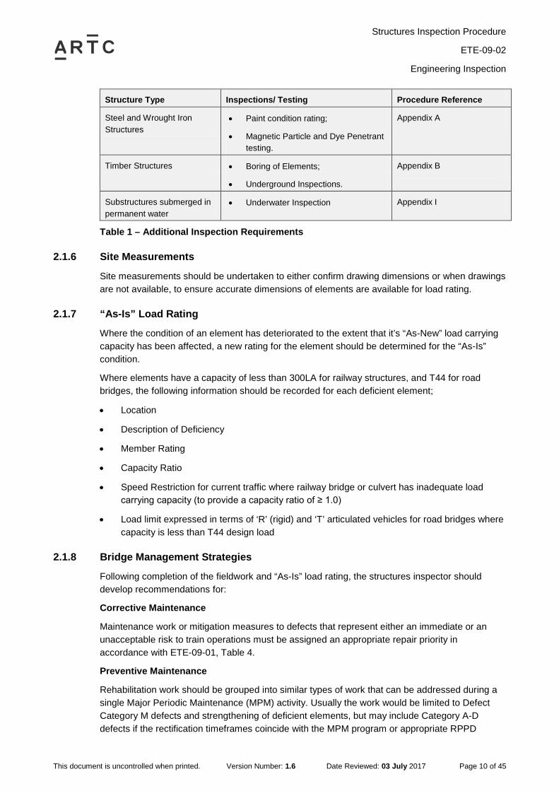
In addition to the inspection requirements outlined above for all structures, it is necessary to undertake specific inspection and/or testing as listed below in Table 2;
Structures Inspection Procedure
ETE-09-02
Engineering Inspection
This document is uncontrolled when printed. Version Number: 1.6 Date Reviewed: 03 July 2017 Page 10 of 45
Structure Type Inspections/ Testing Procedure Reference
Steel and Wrought Iron Structures
• Paint condition rating;
• Magnetic Particle and Dye Penetrant testing.
Appendix A
Timber Structures • Boring of Elements;
• Underground Inspections.
Appendix B
Substructures submerged in permanent water
• Underwater Inspection Appendix I
Table 1 – Additional Inspection Requirements
2.1.6 Site Measurements
Site measurements should be undertaken to either confirm drawing dimensions or when drawings are not available, to ensure accurate dimensions of elements are available for load rating.
2.1.7 “As-Is” Load Rating
Where the condition of an element has deteriorated to the extent that it’s “As-New” load carrying capacity has been affected, a new rating for the element should be determined for the “As-Is” condition.
Where elements have a capacity of less than 300LA for railway structures, and T44 for road bridges, the following information should be recorded for each deficient element;
• Location
• Description of Deficiency
• Member Rating
• Capacity Ratio
• Speed Restriction for current traffic where railway bridge or culvert has inadequate load carrying capacity (to provide a capacity ratio of ≥ 1.0)
• Load limit expressed in terms of ‘R’ (rigid) and ‘T’ articulated vehicles for road bridges where capacity is less than T44 design load
2.1.8 Bridge Management Strategies
Following completion of the fieldwork and “As-Is” load rating, the structures inspector should develop recommendations for:
Corrective Maintenance
Maintenance work or mitigation measures to defects that represent either an immediate or an unacceptable risk to train operations must be assigned an appropriate repair priority in accordance with ETE-09-01, Table 4.
Preventive Maintenance
Rehabilitation work should be grouped into similar types of work that can be addressed during a single Major Periodic Maintenance (MPM) activity. Usually the work would be limited to Defect Category M defects and strengthening of deficient elements, but may include Category A-D defects if the rectification timeframes coincide with the MPM program or appropriate RPPD
Structures Inspection Procedure
ETE-09-02
Engineering Inspection
This document is uncontrolled when printed. Version Number: 1.6 Date Reviewed: 03 July 2017 Page 11 of 45
actions have been programmed for the defect, e.g. scheduled intermediate inspections to ensure the defect does not deteriorate.
The recommendations for MPM work should take into account work already programmed for that structure.
Special Inspections
The structures inspector may recommend that Special Inspections are undertaken to monitor specific defects. Where a Special Inspection is currently being undertaken, the structures inspector may recommend a change in the frequency of the Inspection if appropriate or recommend the inspections are no longer required.
Special Inspections may also be scheduled as part of the RPPD strategy for a structure.
Engineering and Visual Inspections
The structures inspector may recommend an increase in the frequency of Engineering and / or Visual Inspections where deemed necessary.
The structures inspector should take into account the overall condition of the structure and the criticality of the line when developing the recommendations.
2.2 Inspection Review
2.2.1 Defects
The structures representative should review all defects within the specified timeframes.
2.2.2 Mitigation/Maintenance Work
Corrective Maintenance
The structures representative should allocate the corrective maintenance work to be actioned within the timeframe allowed by the allocated Repair Priority the structures representative should also arrange any short term mitigation actions recommended by the structures inspector.
Preventive Maintenance
For preventive maintenance work, the structures representative should develop MPM strategies for the structure taking into account the recommendations of the structures inspector.
2.2.3 Engineering Inspection Report
The structures inspector should submit a draft engineering report containing a summary of critical defects, deficient elements, speed restrictions, load ratings, fatigue assessments, recommended inspection frequencies and short term mitigation actions within the timeframes identified in the Inspection Standard, ETE–09–01.
2.2.4 Overall Review of Inspection Report
Following successful resolution of all of the above issues, the structures inspector should upload the report, including all ratings, calculations, etc., into Ellipse.
The structures representative shall ensure any requirement for special inspections, speed restrictions, etc. is actioned in Ellipse.
Structures Inspection Procedure
ETE-09-02
Visual Inspection
This document is uncontrolled when printed. Version Number: 1.6 Date Reviewed: 03 July 2017 Page 12 of 45
3 Visual Inspection The purpose and scope of a Visual Inspection is provided in the Standard ETE-09-01 Structures Inspection.
Further general information for specific types of structures is provided in the appendices of this procedure. These appendices provide general guidance only and it is expected the Structures Inspector will use appropriate judgement and experience when recommending actions from a Visual Inspection.
3.1 Inspection Procedure The process of undertaking a Visual Inspection is shown in the flowchart in Appendix M.
3.1.1 Pre Inspection Investigation
Prior to undertaking a Visual Inspection the Structures Inspector should review the available relevant historical information for the structure, including;
• Available inspection, engineering and any investigation reports
• Maintenance history
• Outstanding defects and planned Major Periodic Maintenance
• Deficiencies identified for future observation
• Structural issues that have been recorded since the last inspection
3.1.2 Preparation for Inspection
In preparation for the Inspection, the Structures Inspector should liaise with the structures representative to ensure the appropriate arrangements are in place to undertake the Inspection, including;
• Safety Plan
• Track protection
• Inspection access arrangements and safety equipment
• Arrangements with relevant authorities/stakeholders
3.1.3 The structures inspector must prepare a Safety Plan and submit to ARTC’s nominated representative for approval. Visual Inspection
A Visual Inspection covers all elements of the structure above ground and water level. Inspections below ground and water level and non-destructive testing, such as MPI, Dye Penetrant or timber boring, may be necessary for specific structures from time to time. The individual elements of the bridge should be visually examined either with the naked eye or through the use of appropriate equipment such as mirrors, telescopic equipment or video recording in order to identify structural defects.
Review of Equipment Register
The Structures Inspector is required to review the existing equipment register data currently held in Ellipse for the structure and identify either;
Structures Inspection Procedure
ETE-09-02
Visual Inspection
This document is uncontrolled when printed. Version Number: 1.6 Date Reviewed: 03 July 2017 Page 13 of 45
• Additional information to make the equipment register data complete
• Modifications to correct data errors or changes arising from maintenance work
Photographic Record of Structure
For each structure, the following photographic records that form part of the equipment register are required;
• A view along the deck system
• One or two views (depending on the size of the structure) showing the elevation of the structure
• One or two representative photographs of more complex structures such as trusses
The Structures Inspector should review the existing photographs in Ellipse for that structure, and take additional photographs if currently inadequate or there has been a substantive change.
Following the inspection, the Structures Inspector should advise the structures representative of any required changes to the equipment register. The structures representative should review the proposed changes and arrange for the changes to be made Ellipse.
Assessment of Previously Reported Defects
At the start of the inspection procedure, the structures inspector should review the status of all existing defects.
Where existing defect records are incomplete, or the defect has changed (i.e. the measurement or severity has increased), the structures inspector should update the defect data entry as necessary.
Where the existing defect has not changed, no further action is required by the structures inspector.
All existing defects shall be retained in Ellipse, even if the defect is deemed to be inert over multiple inspections. The structures inspector may recommend to ARTC’s designated representative that a defect should be closed in Ellipse if it has been rectified or the record is identified as being erroneous.
New Deficiency Identification
New defects identified by the structures inspector during an inspection shall have a defect record created in Ellipse. The defect record shall be created in accordance with this section of the CoP, and as per the data requirements specified in EGW-10-01.
Establishing the cause of an observed defect is crucial to determining the severity of a defect. If the structures inspector is unable to determine the mechanism responsible for the cause of a defect, further input should be sought from a specialist engineer. If the cause of a defect cannot be identified and the level of risk cannot be determined, further investigation should be recommended.
The structures inspector should take into account the required response timeframes documented in Table 8 in ETE-09-01.
Photographic records are required for all defects.

Structures Inspection Procedure
ETE-09-02
Special Inspection
This document is uncontrolled when printed. Version Number: 1.6 Date Reviewed: 03 July 2017 Page 14 of 45
Data Proformas
ARTC shall provide proformas to collate data from work tasks where the data requirements are not specified in EGP-10-01 or EGW-10-01, or the data cannot be currently stored in Ellipse (e.g. timber boring).
3.2 Inspection Review
3.2.1 Defects
The structures representative shall review all defects within the specified timeframes.
3.2.2 Mitigation/Maintenance Work
Corrective Maintenance
The structures representative should allocate the corrective maintenance work to be actioned in accordance with the agreed repair priorities. The structures representative should also arrange for any short term mitigation actions to be implemented.
Preventive Maintenance
For preventive maintenance work, the structures representative should review the outcomes of the Visual Inspection against the proposed MPM works for the structure and make modifications as required.
3.2.3 Overall Review of Inspection Report
Following successful resolution of all of the above issues the structures representative should upload the accepted visual inspection report into Ellipse.
The structures representative shall ensure any requirement for special inspections, speed restrictions, etc. is actioned in Ellipse.
4 Special Inspection The purpose and scope of a Special Inspection is provided in ETE-09-01.
4.1 Inspection Procedure Special Inspections should generally be carried out in accordance with Section 3.1 of this Procedure.
5 Track Patrol The purpose and scope of a Track Patrol inspection is provided in Standard ETE-09-01 Structures Inspection.
5.1 Inspection Procedure Track Patrols should be carried out in accordance with ARTC Code of Practice (Track & Civil).
Structures Inspection Procedure
ETE-09-02
All defects should be reported to the structures representative, who should arrange for assessment and upload into Ellipse. Appendix A – Inspection of Steel Structural Elements
This document is uncontrolled when printed. Version Number: 1.6 Date Reviewed: 03 July 2017 Page 15 of 45
5.2 Data Recording
6 All defects should be reported to the structures representative, who should arrange for assessment and upload into Ellipse. Appendix A – Inspection of Steel Structural Elements
6.1 Steel Degradation In general, steel deteriorates in service in the following ways; 4.
a. Erosion or corrosion at exposed surfaces, and at timber or concrete interfaces
b. Cracking in elements or welds
c. Relaxation of fastenings
d. Distortion due to overload, or from direct impact from road or rail vehicles
e. Fatigue from repetition of external loading
6.2 Inspection Methods The principal inspection methods are;
Visual
Most cracks in steel bridges are first detected by visual inspection. Once a crack is found, other non-destructive inspection methods, such as dye Penetrant and magnetic particle, are used to further clarify the extent of the crack.
The usual and most reliable sign of fatigue cracks is the oxide or rust stains that develop after the paint film has cracked. Experience has shown that cracks have generally propagated to a depth between one-fourth and one-half the plate thickness before the paint film is broken, permitting the oxide to form. This occurs because the paint is more flexible than the underlying steel.
In Broad Flange Beams inspect for notches caused by impact from vehicles or equipment. Report on loss of section on completion of grinding as required.
Inspect for water build-up, especially in areas that could cause corrosion.
Inspect for loose fasteners. The most reliable sign for loose structural fasteners is the leaching of rust stains from the interface of the connecting elements.
Elements are to be observed under load where possible, and any excessive movement in elements or fastenings is to be noted.
Hammer Test
When elements are tapped lightly with an inspector’s hammer, it will help to identify loose plates and fastenings, the extent of corrosion, and effectiveness of corrosion protection. Care must be taken that hammering does not cause unnecessary destruction of protection systems.
Specialist inspection methods, including X-Ray, Ultrasonic, Acoustic Emission, and Laboratory analysis of steel samples, are beyond the normal scope of Visual Inspections and Engineering Inspections.
Structures Inspection Procedure
ETE-09-02
All defects should be reported to the structures representative, who should arrange for assessment and upload into Ellipse. Appendix A – Inspection of Steel Structural Elements
This document is uncontrolled when printed. Version Number: 1.6 Date Reviewed: 03 July 2017 Page 16 of 45
Advanced Inspection Techniques
Magnetic Particle Testing (MPI) or flaw detection penetrant dye will detect suspected cracking not clearly visible. The local area is to be cleaned back to bare metal to perform the testing. The bare metal shall be re-primed with an appropriate paint system if no crack is found.
Where protective coatings are showing signs of deterioration, or where remote faces of steel elements preclude surface inspection, a dry film thickness gauge or ultrasonic flaw detector device should be used to determine relevant thickness of coating or steel section.
6.3 Element Inspection General
Examine elements for;
• Corrosion and section loss
• Buckled webs, web stiffeners and flanges
• Cracks in webs, flanges and welds
• Loose bolts, rivets, plates and bars
• Paintwork condition
• Distortion from corrosion products
• Stain trails indicating hidden corrosion
• Polished surfaces indicating movement between elements
Particular defect areas to be examined are;
Main Girders (Plate Web or Rolled Section)
Corrosion under transoms or decking, at toes of bottom flange angles between flange plates, 1.around bearings, at abutments and piers, at bracing connections, in rivet and bolt heads
Loose rivets or bolts in flange angles, splices, bracing connections, web stiffeners and 2.splices, bearing plates
Cracks in bottom flange (tension zone), particularly in the area of mid-span 3.
Cracked welds in flange/flange fillets, web stiffeners with diaphragm bracing, bottom of web 4.stiffeners, web/flange fillets
Notches in bottom flanges from road vehicle impact, particularly in Broad Flange Beams 5.
Cracks, loss of section or buckling in webs at ends of girders 6.
Buckled webs of unstiffened girders 7.
Cross Girders
Corrosion under transoms or decking, at toes of bottom flange angles between flange plates, 1.around bearings, at abutments and piers, at bracing connections, in rivet and bolt heads
Cracks in flanges and webs at ends of girders 2.
Loose rivets or bolts in connections 3.
Structures Inspection Procedure
ETE-09-02
All defects should be reported to the structures representative, who should arrange for assessment and upload into Ellipse. Appendix A – Inspection of Steel Structural Elements
This document is uncontrolled when printed. Version Number: 1.6 Date Reviewed: 03 July 2017 Page 17 of 45
Stringer Girders
Corrosions under transoms or decking 1.
Cracks in bottom flange, particularly in the area of mid-span 2.
Cracks in top fillets at ends of girders 3.
Loose rivets or bolts in connections 4.
Detailing 5.
Bearings
Corrosion at flange plate/end bearing stiffener connections 1.
Cracks in bearing or bed plates 2.
Cracked welds between flanges and bearing plates 3.
Loose, broken or missing holding down bolts, studs, and clips 4.
Ineffective sliding, roller or segmented expansion bearings 5.
Expansion bearings not working and segmented bearings lying over 6.
Truss Girders
Corrosion in top and bottom chords, batten plates and lacing bars, portal and wind bracing 1.over tracks, gusset plates, rivet and bolt heads
Misalignment or distortion in chords 2.
Cracks in cleats and connector plates 3.
Loose rivets or bolts and turnbuckles 4.
Damaged steelwork from equipment or loads traveling out-of-gauge 5.
Stepways / Stairways
Corrosion at base connection, stepway risers, stringer webs, tread cleats and clips 1.
Loose bolts and clips to treads 2.
Trestles
Corrosion around baseplates, between angles in bracing, in rivet heads and holding down 1.bolts
Loose rivets or bolts in connections to girders or bracing 2.
Loose turnbuckles in bracing 3.
Piers/Caissons
Corrosion at crosshead connection at water or ground level 1.
Excessive movement of any element under load 2.
Cracks in cylinder walls 3.
Corrugated Steel Pipes
Corrosion in corrugation 1.
Distortion in pipe profile 2.
Structures Inspection Procedure
ETE-09-02
All defects should be reported to the structures representative, who should arrange for assessment and upload into Ellipse. Appendix A – Inspection of Steel Structural Elements
This document is uncontrolled when printed. Version Number: 1.6 Date Reviewed: 03 July 2017 Page 18 of 45
Breakdown of coating 3.
Change in invert alignment indicating bedding failure 4.
Rivets
There are two types of rivets in the bridge system;
• Structural rivets – rivets that need to be tightly fitted e.g. rivets connecting stringer to cross girder or lacing bars to top and bottom chords. Inspect for leaching of rust stain or looseness apparent to a hammer tap
• Stitching rivets – that do not need to be tightly fitted to hold the elements together e.g. rivets connecting diagonal lacing bars or lacing bar spacers in truss bridges. Inspect for slackness due to excessive wear and tear
Deflection
Deflection in steel elements is normally small. Any clear movement under live load is to be measured, or closely estimated, and reported.
Temporary Supports
Inspect visually for soundness and effective support, including footing, foundation and drainage. Packing and wedges are to be tightened and secured as necessary. Where temporary supports have been in service for more than 1 year they must be thoroughly inspected in the same manner as other elements of the structure.
6.4 Broad Flange Beam Introduction
Broad Flange Beam (BFB) spans over roadways are subject to a significant risk of fatigue and/or brittle fracture if damaged by road vehicle impact. The beams become brittle when the ambient temperature is less than 13°C. In order to minimize this risk all such structures are included in a special inspection program during winter months.
Inspection
The spans are to be examined for evidence of flange damage, i.e. cracking, notching, bruising, distortion, scores, and bends) as well as grinding or other repairs. Note that cracks can develop from previously ground or repaired areas.
Inspection must be carried out from close proximity to enable measurement of defects, and to give a reasonable chance of detection of cracking on any surface of the flanges.
Where there are welded flange plates special attention must be given to the BFB flange in the proximity of the welds, as there is a possibility of crack initiation and propagation from welds.
Recording
Each notch is to be individually measured and recorded. Where the flange is bent laterally or vertically, an estimate of the distance is to be recorded. The report should indicate whether damage is in the BFB flange, or the flange plate, or both.
Site action to be taken when cracking or damage occurs.
Where any cracking is found in the BFB bottom flange / flange plate / cover plate area, the structures representative is to be informed immediately and a speed restriction imposed, or the
Structures Inspection Procedure
ETE-09-02
All defects should be reported to the structures representative, who should arrange for assessment and upload into Ellipse. Appendix A – Inspection of Steel Structural Elements
This document is uncontrolled when printed. Version Number: 1.6 Date Reviewed: 03 July 2017 Page 19 of 45
track closed, or the bridge temporarily supported, depending on the extent of the crack as detailed below.
If the track is not closed the bridge must be monitored very closely and a speed restriction imposed to suit. A significant risk and rapid crack growth exists with any unplated BFB showing any crack, or a plated span showing cracks in both BFB and plate flanges. Plated flanges showing cracks in one element, but not in both, are less of a risk.
If a span is temporarily supported at a crack, trains may run indefinitely up to 50km/h depending on the quality of the supports.
If a span is not temporarily supported at a crack, the following action is required:
• If the flange is plated and a crack up to 25mm exists in either the BFB flange or in the flange plate, speed is to be limited to 20km/h, and the crack is to be checked after each train
• If the crack is greater than 25mm but less than 100mm, road traffic is to be suspended during the passage of rail traffic
• If the crack is greater than 100mm, rail traffic must NOT be permitted
• Where the flange is not plated or both flange and flange plate are cracked, rail traffic may be permitted if the crack is up to 25mm long. Rail speed must be limited to 20km/h, road traffic must be stopped during the passage of each train, and the crack is to be checked after each train
• Where the flange is not plated or both flange and flange plate are cracked, and the crack is over 25mm, rail traffic is to be stopped
Repair method
No welding, straightening or cutting is to be done on BFB spans without the prior approval of ARTC.
6.5 Additional Inspection Requirements When undertaking an Engineering Inspection for a Steel Bridge the structures inspector shall provide the following additional information;
Paint Condition Rating
Paint Condition Ratings are to be assigned by the structures inspector to reflect the condition of the surface coating for the overall structure. The ratings are defined as follows;
Poor: Paint broken down throughout. Program to paint within 10 years.
Fair: Paint broken down locally. Patch paint as required within 5 years.
Good: Paint in satisfactory condition.
Painting not required: The structure is located in a benign environmental location area where the rate of corrosion is low and corrosion of steel structural elements will not significantly affect the design life of the structure.
Non Destructive Testing
Non-destructive testing (NDT) shall be carried out on site to verify cracks and crack lengths where;
• Cracks on wrought iron structural elements exceed 50mm
Structures Inspection Procedure
ETE-09-02
All defects should be reported to the structures representative, who should arrange for assessment and upload into Ellipse. Appendix A – Inspection of Steel Structural Elements
This document is uncontrolled when printed. Version Number: 1.6 Date Reviewed: 03 July 2017 Page 20 of 45
• Any new crack, or any extension to a previously noted crack, on steel structural elements
The NDT shall include;
• Magnetic Particle Testing
• Liquid Penetrant Testing
The structures inspector is required to have the competency to undertake the testing, or arrange for the testing to be undertaken by someone with sufficient competency. The minimum level of competency acceptable to ARTC is successful completion of a Level 1 – Liquid Penetrant and Magnetic Particle Testing Methods course that meets the requirements of AS 3998 – 2006 - "Non-destructive testing—Qualification and certification of person.
Structures Inspection Procedure
ETE-09-02
Appendix B – Inspection of Timber Structural Elements
This document is uncontrolled when printed. Version Number: 1.6 Date Reviewed: 03 July 2017 Page 21 of 45
7 Appendix B – Inspection of Timber Structural Elements
7.1 BridgeWood Decking The BridgeWood decking consists of specially designed and treated plywood panels which are specifically designed for both road and rail bridge applications. It requires the similar examinations to traditional hardwood timber components to ensure continued safety of traffic operation.
7.2 Timber degradation In general, timber deteriorates in service only when attacked by outside agencies. These can be categorized as follows;
• Weathering at exposed surfaces
• Decay or rot
• Insect attack, whether termites or borers
• Fire
• Mechanical damage from vehicles or equipment
• Checks and splits
Of the above categories, decay and insect attack usually cause deterioration inside an element and therefore are the hardest to measure.
7.3 Inspection methods The principal timber inspection methods are;
Visual inspection
All bridge elements are to be inspected for indications of deterioration or damage such as;
• Weathering, cracks, shakes, splits
• Bubbles, especially in laminated panel indicating internal de-lamination
• Surface decay where elements join or where elements project behind abutments
• Damp sides of elements, especially of timber decking
• Indicators of internal decay such as troughing, sides bulging, brooming out of fibres, body bolts hanging out or loose in their holes
• Termite or fungus attack
• Crushing of elements, especially headstocks, at seating and joints
• Spike killing of transoms
• Loose or missing bolts, including transom bolts
Hammer Testing
Hammering, or sounding, a timber element gives an indication of internal deterioration. The presence of delamination, rot or termite attack may cause a hollow sound when struck by the
Structures Inspection Procedure
ETE-09-02
Appendix B – Inspection of Timber Structural Elements
This document is uncontrolled when printed. Version Number: 1.6 Date Reviewed: 03 July 2017 Page 22 of 45
hammer, indicating boring is required. The hammer should weigh about 1kg, with one face flat and the other face spiked.
Bore and Probe
Test boring is carried out with a 10 mm auger in order to locate internal defects such as pipes, rot or termites. Holes are bored square to the face of girders, corbels, headstocks, piles, sills and other elements, as necessary. Boring must not be overdone and holes are to be preservative treated and plugged, leaving the plug 20mm proud. Unused holes are to be plugged flush. The extent of an internal pipe or other defect is found and measured with a feeler gauge made from 4 mm steel wire with one end flattened and about 4 mm bent over at right angle. By probing down the bore hole, the extent of a defect can be felt, measured and recorded.
NOTE: No boring of BridgeWood decking is required because the Engineered Wood Product is not subject to piping or internal rot as in sawn hardwood.
Deflection Test
A deflection test gives an indication of girder condition and riding quality.
Deflections are to be measured at the mid-point of all girders in the tested span and recorded. If deflection limits are exceeded at permitted track speed, temporarily reduce train speed to suit. If the limit is exceeded at 20 km/h, the structures representative is to be advised the same day.
7.4 Inspection procedure The following inspections are to be undertaken by the inspector:
Transoms
Inspect for weathering, splitting, crushing, spike killing, fire damage, condition at rail seating, and condition at girder bearings for intermediate transoms.
Ballast Walls
Inspect for general condition, tightness of bolts, and capacity to retain ballast.
Runners
Inspect for general condition and tightness of bolts.
Decking
Determine the general condition of the timber decking. Note the number, size and location of pieces split, or with more than twenty percent (20%) section loss.
Ballast Logs
Inspect for general condition and tightness of bolts.
Girders
Inspect visually and hammer test for soundness. Bore new holes and probe girders at each Engineering Inspection. Inspect compound girders individually. If necessary, the inspector may bore during a Visual Inspection preferably using existing holes.
Girders are to be inspected for signs of decay, particularly where this may be occurring on the top surface under the decking of ballast top spans. Bore girders horizontally at mid depth over corbel ends or sill face and at centre span.
Structures Inspection Procedure
ETE-09-02
Appendix B – Inspection of Timber Structural Elements
This document is uncontrolled when printed. Version Number: 1.6 Date Reviewed: 03 July 2017 Page 23 of 45
Where a pipe is found over 125 mm wide, cross bore vertically at the location and note size and position of the pipe. Where visual inspection raises any doubt or where termites appear active, additional boring is to be carried out as necessary.
Check the bearing areas for crushing of the beams near the bearing seat. Investigate for decay and insect damage by visual inspection and sounding and/or probing at the ends of the beams where dirt, debris, and moisture tend to accumulate.
Investigate the area near the supports for the presence of horizontal shear cracking. The presence of transverse cracks on the underside of the girders or horizontal cracks on the sides of the girders indicate the onset of shear failure.
Inspect the zones of maximum tension for signs of structural distress. The maximum tension generally occurs at the bottom half of the middle third of the beam span. Tension cracks in timber break the cell structure perpendicular to the grain and are typically preceded by the appearance of horizontal shear cracks.
Corbels
Inspect in a similar manner to girders. Bore holes to be 300 mm from each end, and at the centre, but clear of bolt holes. Where packing is installed, the location, size and type are to be noted.
Headstocks
Inspect visually and hammer test for soundness. Identify solid and double waling types. Bore and probe ends of elements if hammer test indicates internal decay. Give special attention to corbel seatings and to pile bearings. Inspect waling headstocks for loose bolts and for bearing on pile shoulders.
Bracing
Inspect all horizontal and diagonal bracing visually and hammer test for soundness. Inspect for loose bolts, and effectiveness of bracing in restraining side-sway.
Sills
Inspect visually and hammer test for soundness. Identify solid and double waling types. Inspect for loose bolts, straps, decay of undersides on concrete bases, and bearing of walings on pile shoulders.
Piles
Inspect visually and hammer test for soundness. Bore new holes during every Engineering Inspection and probe at headstock level and at ground level.
Inspection below ground is required during Engineering Inspection, using a backhoe where possible. Excavate to a depth of 500 mm, or more if necessary, and bore at trench bottom. Where spliced piles show signs of vertical or sideways movement, the splice rails and pipe stumps are to be exposed and inspected. All excavations are to be backfilled, rammed, and scour protection reinstated. If necessary, the Structures Inspector may bore new holes during a Visual Inspection
Spliced and planted piles are to be specially noted. Depth of splice, or of plant footing, below bottom waling is to be noted. Where piles have a surrounding concrete collar or invert, the concrete must not be cut away for inspection unless extensive pile necking or piping is evident.
Inspect piles in permanent water during Engineering Inspection, or more frequently depending on deterioration shown at the previous inspection, or if major scouring is suspected. The underwater inspection should be carried out in accordance with the guidance of this Procedure.
Structures Inspection Procedure
ETE-09-02
Appendix B – Inspection of Timber Structural Elements
This document is uncontrolled when printed. Version Number: 1.6 Date Reviewed: 03 July 2017 Page 24 of 45
At Engineering Inspections, when the cross-sectional area of a pile is found to be degraded to 50% of its original cross sectional area the following procedure is required. The defect is to be rated a Defect Category D. Subsequently any such degraded pile that is assessed to be performing satisfactorily and deemed to be able to remain in place, must then have 2 yearly cyclic boring carried out (i.e. at the normal cyclic visual inspections).
Abutment sheeting and wing capping
Inspect for general condition and for ability to retain backfill. Inspect sheeting behind girders of end spans.
Walkways and Refuges
Inspect for overall safety.
Truss spans
Inspect truss elements generally, as for girder spans. Bore new holes and probe top chords, bottom chords, cross girders, stringers and end posts at element ends. Tighten tension elements, taking care to avoid crushing of timber in joints.
Timber box drains
Inspect visually for general condition, and note any indication of failure of roof or wall timbers.
Temporary supports
Inspect visually for soundness and effective support, including footing, foundation and drainage. Packing and wedges are to be tightened and re-spiked where necessary. Where temporary supports have been in service for more than 1 year they must be thoroughly inspected, including new bore holes, in the same manner as other elements of the structure.
Termites and Fungus
Termite infestations found either visually or by boring during inspection are to be reported to the structures representative immediately. Suspected areas of fungal attack could be inspected by prodding the exposed surface with a sharp probe to detect areas of softness compared to the surrounding good timber.
Screwing Up
During the inspections, all bolts are to be inspected and tightened as necessary.
Packing is to be inspected, repacked and spiked as necessary.
Site condition
All dry grass, flood debris, and other foreign matter that may cause a fire hazard, or may accelerate timber decay, must be removed from the immediate vicinity of the bridge element.
Structures Inspection Procedure
ETE-09-02
Appendix C – Inspection of Concrete Structural Elements
This document is uncontrolled when printed. Version Number: 1.6 Date Reviewed: 03 July 2017 Page 25 of 45
8 Appendix C – Inspection of Concrete Structural Elements
8.1 Concrete Degradation In general, concrete deteriorates in service in the following ways; 1.
a. Weathering or spalling at exposed faces, resulting from erosion, poor quality concrete, chemical action, water action, corrosion of reinforcement, low cover to reinforcing bars, crushing at bearing surfaces and poorly compacted concrete
b. Cracking from loading changes, including settlement
c. Mechanical damage, especially collision damage from road or rail vehicles, or abrasion
8.2 Inspection Methods The principal inspection methods are;
Visual
Visual inspection will detect most defects in concrete structural elements. The inspector is to look for signs of;
• Weathering or spalling of surfaces or mortar joints
• Cracking within elements or at joints
• Stains on surfaces indicating reinforcement corrosion
• Crushing especially at bearings or at pre-stressing anchorage points
• Changed alignment of elements
o vertically, e.g. abutments;
o horizontally, e.g. deck camber
o laterally, e.g. footings and culverts
Cracking in concrete structural elements is an indicator of weakness in the element. Cracks must be examined for size and movement under load, and details recorded. Shrinkage or hairline cracks need be noted only.
Cracking or crushing around pre-stressing anchorages must be noted.
Length, width, and location of cracks are to be measured. A short line scribed across the midpoint of a crack will give easy indication of further movement. Reference points scribed at each end of the line can be measured to indicate changes in crack width.
Examine all elements for the unplanned ingress of water. Scuppers, weep holes, and other outlets are to be cleared of rubbish. Any water build-up, or seepage into unwanted areas, is to be reported.
Hammer Test
Hammer testing, where surfaces are tapped lightly with an examination hammer, can indicate “drumminess” (a dull hollow sound) and potential spalling areas.
Structures Inspection Procedure
ETE-09-02
Appendix C – Inspection of Concrete Structural Elements
This document is uncontrolled when printed. Version Number: 1.6 Date Reviewed: 03 July 2017 Page 26 of 45
Advanced Inspection Techniques
Where the cause of cracking or bulging of an element cannot be explained by visual inspection, specialist testing such as X-Ray, Ultrasonic, and Acoustic Emission can be used to examine the internal condition of structures and the underlying cause of the observed defects. The inspector is to note such concerns for follow-up by the structures representative.
8.3 Locations Bearing Areas
Examine bearing areas for spalling where friction from thermal movement and high bearing pressure could cause the concrete to spall. Check for crushing of the stem near the bearing seat. Check the condition and operation of any bearings.
Shear Zones
Investigate the area near the supports for the presence of shear cracking. The presence of transverse cracks on the underside of the stems or diagonal cracks on the sides of the stem indicate the onset of shear failure. These cracks represent lost shear capacity and should be carefully measured.
Tension Zones
Check for deteriorated concrete in the tension zones, which could result in the debonding of the tension reinforcement. This would include delamination, spalls, and contaminated concrete. Cracks greater than 2 mm wide are considered wide cracks and indicate extreme bending stresses. They should be measured and recorded.
Cracks
Check for efflorescence from cracks and discoloration of the concrete caused by rust stains from the reinforcing steel. In severe cases, the reinforcing steel may become exposed due to spalling. Document the effective cross section of reinforcing steel since section loss will decrease live load carrying capacity of the element.
Deflection
Deflection in concrete elements is normally small. Any clear movement under normal traffic load is to be measured and reported.
Diaphragms
Diaphragms should be inspected for flexure and shear cracks as well as typical concrete defects. Cracks in the diaphragms could be an indication of overstress or excessive differential deflection between adjacent beams.
Areas Exposed to Drainage
Check around scuppers, inlets or drain holes for leaking water or deterioration of concrete.
Structures Inspection Procedure
ETE-09-02
Appendix D – Inspection of Fibre Composite Structural Elements
This document is uncontrolled when printed. Version Number: 1.6 Date Reviewed: 03 July 2017 Page 27 of 45
9 Appendix D – Inspection of Fibre Composite Structural Elements
9.1 Fibre Composite Degradation In general, Fibre Composite products deteriorate in service in the following ways;
Surface cracking
• When overstressed due to excessive loading a non-structural coating or paintwork on element will show signs of fine cracks or spalling at bottom and on side surfaces at load point
• On impact the coating may spall, split or crack. Small localized damage is of no immediate engineering concern however, all damages should be reported
Crushing
• Crushing at load points (on edges at bearings or around bolt holes) is most likely an indication of excessive loading. The coating will show signs of discoloring/spalling. All such discoloring/spalling shall be reported
Wear and tear
• Excessive wear and tear or overstressing at bolt holes will show signs of discoloring or spalling in the coating. Loose fasteners will indicate wearing in threads of material
Fire Damage
• The coating can be subject to fire damage in much the same way as timber however, the Fibre Composite product itself will withstand intense heat/fire
• To determine the extent to which the element is affected, any lose or charred material must be removed until unburned material is exposed. If the fire damage is limited to the protective layer no immediate engineering concern exists however all fire damages should be reported
9.1.1 Inspection
• Fibre Composite material will not rot or decay and it is resilient to any attack by termites or fungus
• A close visual inspection is to be made of all exposed surfaces
• No boring for inspection purpose shall be undertaken as it will not reveal any internal defects
• No chemical etching or hard tapping with any object shall be undertaken
9.2 Inspection Methods The principal inspection methods are;
Visual
Visual inspection will detect most defects in fibre composite structural elements. The inspector is to look for signs of:
• Cracking within elements or at joints
• Stains or discolouring on surfaces indicating overstressing of localized area
• Crushing especially at bearings or load points
Structures Inspection Procedure
ETE-09-02
Appendix D – Inspection of Fibre Composite Structural Elements
This document is uncontrolled when printed. Version Number: 1.6 Date Reviewed: 03 July 2017 Page 28 of 45
• Changed alignment of elements;
o Cracking in structural elements is an indicator of weakness in the element. Cracks must be examined for size and movement under load, and details recorded. Shrinkage or hairline cracks need be noted only
o Length, width, and location of cracks are to be measured. A short line scribed across the midpoint of a crack will give easy indication of further movement. Reference points scribed at each end of the line can be measured to indicate changes in crack width
Hammer Test
Hammer testing, where surfaces are tapped lightly with an examination hammer, can indicate “drumminess” and potential spalling areas.
Advanced Inspection Techniques
Where the cause of cracking or bulging of an element cannot be explained by visual inspection, specialist testing such as X-Ray, Ultrasonic, and Acoustic Emission can be used to examine the internal condition of structures and the underlying cause of the observed defects. The inspector is to note such concerns for follow-up by the structures representative.
9.3 Locations Bearing Areas
Examine bearing areas for spalling where friction from thermal movement and high bearing pressure could cause the fibre composite to wear/spall. Check for crushing of the stem near the bearing seat. Check the condition and operation of any bearings.
Shear Zones
Investigate the area near the supports for the presence of shear cracking. The presence of transverse cracks on the underside of the stems or diagonal cracks on the sides of the stem indicate the onset of shear failure. These cracks represent lost shear capacity and should be carefully measured.
Tension Zones
Check for cracks in the tension zones, which could result in the debonding of any tension reinforcement. This would include delamination and spalls. All cracks must be measured and recorded.
Cracks
Check for efflorescence from cracks and discoloration of the coating caused by overloading.
Deflection
Deflection in elements is normally small. Any clear movement under normal traffic load is to be measured and reported.
Structures Inspection Procedure
ETE-09-02
Appendix E – Inspection of Interflow Expanda & Rotaloc Pipes
This document is uncontrolled when printed. Version Number: 1.6 Date Reviewed: 03 July 2017 Page 29 of 45
10 Appendix E – Inspection of Interflow Expanda & Rotaloc Pipes
10.1 General
• Expanda & Rotaloc pipe products are two different methods of fabricating new drainage pipes or lining the interior surfaces of severely corroded corrugated steel pipes (CSP) to strengthen them to railway design loading 300LA.
• The liners are designed to sustain full design load without sharing any design loads with the existing corroded pipe.
• The annulus between the Interflow liner and CSP pipe is then pressure grouted with cementitious grout.
• These products are made from PVC or HDPE Plastic by Interflow Ltd, an Australian based company.
• ARTC has approved use of Expanda & Rotaloc pipes/liners for pipes up to 1000mm and 1500mm diameter respectively.
10.2 Expanda & Rotaloc Degradation Unlike steel and concrete, polyethylene and PVC don’t corrode in acidic conditions and don’t need protective coatings that need to be maintained. The liners are continuous and don’t have fasteners, bolts, etc.
In general, the products deteriorate in service in the following ways;
Deformation
• As the products are flexible, deformation would indicate overstressing due to excessive loading or loss of embedment support, most likely caused by scouring around the outside of the liner and would need to be addressed
Cracked barrel / Joint broken or separated
• When overstressed due to excessive loading the pipe will develop cracks or joint separation
Abrasion in sectional area
• While PVC and Polyethylene are more abrasion resistant than steel or concrete, the liners/pipes should be inspected for any evidence of abrasion, particularly in floor
Fire / Ultra Violet Radiation damage
• The products could be subject to fire/UVR damage however, they will withstand intense heat/fire
10.2.1 Inspection
• Expanda and Rotaloc material will not rot or decay and it is resilient to any attack by termites or fungus
• A close visual inspection is to be made of all exposed surfaces
• No boring for inspection purpose shall be undertaken as it will not reveal any internal defects
• No chemical etching or hard tapping with any object shall be undertaken
Structures Inspection Procedure
ETE-09-02
Appendix E – Inspection of Interflow Expanda & Rotaloc Pipes
This document is uncontrolled when printed. Version Number: 1.6 Date Reviewed: 03 July 2017 Page 30 of 45
10.3 Inspection Methods The principal inspection methods are;
Visual
Visual inspection will detect most defects in Expanda and Rotaloc pipes. The inspector is to look for signs of;
• Deformation
• Settlement / Changed alignment
• Cracking/Disjointing
• Abrasion
• Fire / UVR damages within elements or at joints
Deformation and/or cracking in pipes are indicators of weakness. These defects must be examined for size and movement under load, and details recorded. All cracks need be noted carefully.
Length, width, and location of cracks are to be measured. A short line scribed across the midpoint of a crack will give easy indication of further movement. Reference points scribed at each end of the line can be measured to indicate changes in crack width.
Hammer Test
Hammer testing, where surfaces are tapped lightly with an examination hammer, can indicate “drumminess” and potential loss of backfill material or undermining of foundation.
10.4 Locations Deformation
As the products are flexible, deformation would indicate overstressing due to excessive loading or loss of embedment support, most likely caused by scouring around the outside of the pipe and would need to be addressed.
Cracked barrel / Joint broken or separated
When overstressed due to excessive loading the pipe will develop cracks or joint separation.
Abrasion in sectional area
While PVC and Polyethylene are more abrasion resistant than steel or concrete, the liners/pipes should be inspected for any evidence of abrasion, particularly in floor.
Fire / Ultra Violet Radiation damage
The products could be subject to fire/UVR damage however, they will withstand intense heat/fire.
Foundation
Examine for differential settlement and undermining of the foundation and around inlet/outlet of pipe.
Deformation
Check for deformation in highly stressed zones at 10 and 2 0’clock and at any other locations along full length of the pipe.
Structures Inspection Procedure
ETE-09-02
Appendix F – Inspection of Masonry Structural Elements
This document is uncontrolled when printed. Version Number: 1.6 Date Reviewed: 03 July 2017 Page 31 of 45
Tension Zones
Check for cracks in the tension zones, which could result in the disjointing along seams. All cracks must be measured and recorded.
Deflection
Deflection in elements is normally small. Any clear movement in roof under normal traffic load is to be measured and reported.
11 Appendix F – Inspection of Masonry Structural Elements
11.1 Overview This section describes typical defects that occur in masonry structures. 2.
11.2 Defects Caused by Structural Distress Excessive Loading
a. Excessive loading, particularly when applied as a point loading, may cause localised crushing of masonry or even displacement of individual masonry units
b. An increase in lateral pressure of earth behind abutments, wing walls and retaining walls may cause forward movement or tilting leading to distortion of the shape of an arch structure and may cause transverse cracking of the arch barrel. Recent cracks would indicate that movement is occurring
c. An increase in lateral forces or pressures in the fill material may destabilize spandrel walls on arch structures
Arch Shape Deformation
Flattening of the arch may be a sign of outward movement of the abutments. Movements may be more easily identified by evidence of dips in the courses of the spandrel walls or the parapets above the arch.
Structural Cracking
Cracks in masonry construction may only affect the appearance but can also be indicative of a more serious underlying defect. The inspector should observe many aspects of the cracking, including length, width, variation of width along its length, location, distribution, and, in some cases, depth. The displacements forwards, backwards and sideways of the masonry on each side of a crack should also be recorded. The current extent of the displacement should, if possible, be marked and dated on the surface of the structure to assist future inspections.
The most serious form of cracking is that caused by structural inadequacy or overloading. The four types of cracking associated with this are described as follows:
• Longitudinal cracks (in direction of span) – Differential settlement or movement across the width of an abutment or pier will produce longitudinal cracks in the arch barrel, as the structure splits apart, dividing the barrel into independent sections. If accessible, the depth of the cracks should be probed to reveal whether or not the whole thickness of the arch barrel has been cracked
• Transverse (lateral) cracks – These may be accompanied by permanent deformations of the arch shape and are caused by partial load failure of the arch or by movement at the supports
Structures Inspection Procedure
ETE-09-02
Appendix G – Inspection of Tunnels
This document is uncontrolled when printed. Version Number: 1.6 Date Reviewed: 03 July 2017 Page 32 of 45
• Diagonal cracks – These normally start near the sides of the arch at the springs and spread up towards the centre of the barrel at the crown. They are generally due to subsidence at the sides of the abutment or pier and are caused by the resultant twisting of the arch
• Longitudinal cracks near the spandrel walls – Longitudinal cracks near the edge of the arch barrel may be a sign that the spandrel wall has been forced outward and, instead of the spandrel wall sliding on the extrados (i.e. the exterior curve) of the arch, the arch ring itself has cracked
11.3 Defects arising due to the nature of the material Arch Ring Separation
The load capacity can be significantly reduced if ring separation has occurred. Separation within the barrel of an arch may be detected by hammer tapping to detect “drumminess” as opposed to a solid “ring” if fully bonded.
Defective Mortar and Pointing
The load carrying capacity of a masonry arch is dependent upon the thickness of the arch ring. If the mortar is missing, loose, or friable, then that depth of the ring affected is unable to transmit load and contribute to the strength of the arch.
Displaced or Missing Stones or Bricks
Deterioration of mortar, localised loading or large structure movements may result in masonry units becoming loose or displaced. The displacement of individual masonry units should be noted; particular emphasis should be made to those at the crown of arches with shallow depths of cover over the crown.
11.4 Defects instigated by external agents Deterioration under these conditions may occur due to one or a combination of two or more of the following reasons;
• Erosion by water and wind and water borne particles, by frost attack and by vegetation root growth
• Chemical/biological attack due to acids, sulphates and chemicals either water-borne or released by water, or from air-borne pollution
• Efflorescence staining
• Moisture and thermal movement of bricks and blocks
12 Appendix G – Inspection of Tunnels Serious deterioration in the stability of a tunnel is evidenced by bulging, distortion, cracking or changing geometry in the tunnel.
Inspection requires a working platform and good lighting so that close examination of the periphery can be made.
Tunnel Inspection should highlight the following indicators;
• The general condition of the rock face in unlined tunnels, or of the lining in others
• The condition of joints in concrete, brickwork and stonework
Structures Inspection Procedure
ETE-09-02
Appendix G – Inspection of Tunnels
This document is uncontrolled when printed. Version Number: 1.6 Date Reviewed: 03 July 2017 Page 33 of 45
• Cracks, spalling, hollows or bulges in tunnel linings
• Ineffective drainage, especially through weep holes and track drains
• Signs of water seepage remote from constructed drainage outlets
• Condition of attachments to tunnel lining
• Track heave, subsidence, or alignment change
• Condition of tunnel refuges and lighting
• Condition of Portals and movement of portal away from tunnel stem
Cracks, bulges, and spalled areas are to be measured for length, position and displacement. Cracks or displacement greater than 10mm should have measurement reference pins.
All extensively cracked areas or individual critical cracks should be adequately mapped and photographed for easy reference during the next inspection.
Structures Inspection Procedure
ETE-09-02
Appendix H – Inspection of Substructure Elements
This document is uncontrolled when printed. Version Number: 1.6 Date Reviewed: 03 July 2017 Page 34 of 45
13 Appendix H – Inspection of Substructure Elements
13.1 Introduction The substructure is the component of a bridge that includes all elements supporting the superstructure. Its purpose is to transfer the loads from the superstructure to the foundation soil or rock. The primary structural elements of the bridge substructure are the abutments (including wingwalls) and the piers (or trestles).
13.2 Inspection procedures Inspection procedures for substructure elements are the principally the same as superstructure elements of similar material type, particularly when it involves material deterioration. However, because stability is a paramount concern, checking for various forms of movement is required.
Vertical Movement
Vertical movement can occur in the form of uniform settlement or differential settlement. A uniform settlement of all bridge substructure units often will have little effect on the structure, although it will affect the vertical alignment of the railway track(s) and road onto and off the structure.
Differential settlement can produce serious distress in a structure. Differential settlement may occur between different substructure units, causing damage of varying magnitude depending on span length and structure type. It may also occur under a single substructure unit causing an opening of the expansion joint between the abutment and wingwall, or it may cause cracking or tipping of the abutment, pier, or wall.
The most common causes of vertical movement are soil bearing failure, consolidation of soil, scour, and deterioration of the abutment foundation material.
Inspection for vertical movement, or settlement, should include;
• Investigate existing and new cracks for signs of settlement
• Examine the superstructure alignment for evidence of settlement (particularly the bridge deck kerbs or railing)
• Check for scour around abutment and pier footings or foundations
• Inspect the joint that separates the wingwall and abutment for proper alignment
• Check for any new or unusual cracking
Lateral Movement
Earth retaining structures, such as abutments and retaining walls, are susceptible to lateral movements, or sliding. Lateral movement occurs when the horizontal earth pressure acting on the wall exceeds the friction forces that hold the structure in place.
The most common causes of lateral movement are slope failure, water seepage, changes in soil characteristics, and time consolidation of the original soil.
Inspection for lateral movement, or sliding, should include;
• Inspect the general alignment of abutments, wingwalls, piers and exposed footings
• Check the bearings for evidence of lateral displacement
Structures Inspection Procedure
ETE-09-02
Appendix H – Inspection of Substructure Elements
This document is uncontrolled when printed. Version Number: 1.6 Date Reviewed: 03 July 2017 Page 35 of 45
• Examine the opening in the construction joint between the wingwall and the abutment
• Investigate the joint opening between the primary elements
• Settlement of fill behind the abutment and wingwalls
• Check the expansion gap at the ends of spans
• Examine for clogged drains and/or water seepage
• Inspect for erosion or scour of the embankment material in front of abutments or pier footings
Rotational Movement
Rotational movement, or tilting, of substructure units is generally the result of unsymmetrical settlements. Abutments and walls are typically subject to this type of movement.
The most common causes of rotational movement are scour, erosion, saturation of backfill, soil bearing failure, erosion of backfill along the sides of the abutment, and poor design.
Inspection for rotational movement, or tilting, should include;
• Check the vertical plumbness of the substructure
• Examine the clearance between individual spans
• Inspect for clogged drains or weep holes and/or water seepage
• Investigate for cracks, and record the crack width, length, and direction
Structures Inspection Procedure
ETE-09-02
Appendix I – Inspection of Underwater Structural Elements
This document is uncontrolled when printed. Version Number: 1.6 Date Reviewed: 03 July 2017 Page 36 of 45
14 Appendix I – Inspection of Underwater Structural Elements
14.1 Introduction Where structural elements are continuously submerged, underwater inspections must be undertaken to establish their condition. Underwater structural elements must be inspected to the extent necessary to determine with certainty that their condition has not compromised the structural integrity of the bridge.
In general, the term "underwater inspection" is taken to mean a hands-on inspection that may require underwater breathing apparatus and related diving equipment.
14.2 Frequency All structures should receive routine underwater inspections at the time of the Engineering Inspection, but special inspections may be implemented more frequently where appropriate for the individual bridge.
Structures inspector can determine underwater examination frequency greater than 6 years for structures other than timber piles and shallow footed piers.
The decision must at least be based on the following factors;
• Last inspection date
• Structure type
• Water flow characteristics
• Risk of scouring
• Risk of deterioration of elements
• Local environment
The underwater examination for rail bridges must not lapse more than 12 years.
14.3 Methods of Underwater Inspection There are three general methods used to perform underwater inspections;
• Wading inspection
• Self-contained diving (SCUBA)
• Surface-supplied diving
Wading Inspection
Wading inspection is the basic method of underwater inspection used on structures with shallow streams. The substructure condition should be evaluated using a probing rod, sounding rod or line, waders, and possibly a boat.
Self-contained Diving (SCUBA)
In this mode, the diver operates independently from the surface, carrying his/her own supply of compressed breathing gas (typically air). This dive mode is best used at sites where environmental and waterway conditions are favorable, and where the duration of the dive is relatively short.
Structures Inspection Procedure
ETE-09-02
Appendix I – Inspection of Underwater Structural Elements
This document is uncontrolled when printed. Version Number: 1.6 Date Reviewed: 03 July 2017 Page 37 of 45
Extreme care should be exercised when using SCUBA equipment at bridge sites where the waterway exhibits low visibility and/or high current, and where drift and debris may be present at any height in the water column.
Surface-Supplied Diving
Surface-supplied diving uses a breathing gas supply that originates above the water surface providing the diver with a nearly unlimited supply of breathing gas, and also provides a safety tether line and hard-wire communications system connecting the diver and above water personnel. Using surface-supplied equipment, work may be safely completed under adverse conditions.
Method Selection Criteria
In determining whether a bridge can be inspected by wading or whether it requires the use of diving equipment, water depth should not be the sole criteria. Many factors combine to influence the proper underwater inspection method including;
• Water depth
• Water visibility
• Current velocity
• Streambed conditions (softness, mud, "quick" conditions, and slippery rocks)
• Debris
• Substructure configuration
14.4 Diving Inspection Intensity Levels Three diving inspection intensity levels have evolved as follows;
• Level I: Visual, tactile inspection
• Level II: Detailed inspection with partial cleaning
• Level III: Highly detailed inspection with nondestructive testing
Level I
Level I inspection consists of a "swim-by" overview at arm’s length with minimal cleaning to remove marine growth. Although the Level I inspection is referred to as a "swim-by" inspection, it must be detailed enough to detect obvious major damage or deterioration. A Level I inspection is normally conducted over the total (100%) exterior surface of each underwater element, involving a visual and tactile inspection with limited probing of the substructure and adjacent streambed.
The results of the Level I inspection provide a general overview of the substructure condition and verification of the as-built drawings. The Level I inspection can also indicate the need for Level II or Level III inspections and aid in determining the extent and selecting the location of more detailed inspections.
Level II
Level II inspection is a detailed inspection that requires that portions of the structure be cleaned of marine growth. It is intended to detect and identify damaged and deteriorated areas that may be hidden by surface growth.
Structures Inspection Procedure
ETE-09-02
Appendix I – Inspection of Underwater Structural Elements
This document is uncontrolled when printed. Version Number: 1.6 Date Reviewed: 03 July 2017 Page 38 of 45
A Level II inspection is typically performed on at least 10% of all underwater elements. The thoroughness of cleaning should be governed by what is necessary to determine the condition of the underlying material. Generally, the critical areas are near the low waterline, near the mud line, and midway between the low waterline and the mud line.
On submerged piles, horizontal bands, approximately 150 to 300 mm in height, should be cleaned at designated locations. On large elements, such as piers and caissons, areas approximately 300mm square should be cleaned at three or more levels on each face of the element (or at quarter points for circular elements). Deficient areas should be measured, and the extent and severity of the damage recorded.
Level III
A Level III inspection is a highly detailed inspection of a critical structure or structural element, or an element where extensive repair or possible replacement is contemplated. The purpose of this type of inspection is to detect hidden or interior damage and loss in cross-sectional area. This level of inspection includes extensive cleaning, detailed measurements, and selected nondestructive and partially destructive testing techniques.
Level III inspections are not included in the scope of Engineering Inspections and will be undertaken as part of a specific investigation.
14.5 Types of Inspection Routine Inspections
A routine inspection is typically undertaken as part of an Engineering Inspection. It is an intermediate level inspection consisting of sufficient observations and measurements;
• To determine the physical and functional condition of the bridge
• To identify any change from "inventory" or previously recorded conditions
• To ensure that the structure continues to satisfy present service requirements
The scope of work for a routine inspection should include;
• A Level I inspection of all the submerged elements
• A Level II inspection on at least 10% of submerged elements
The dive team should also conduct a scour evaluation at the bridge site, including inspecting the channel bottom and sides for scour and, in particular, checking for local scour in the vicinity of submerged elements.
Damage Inspections
Certain conditions and events affecting a bridge may require more frequent, or unscheduled, inspections to assess structural damage resulting from environmental or accident related causes.
A Level III inspection may be necessary to determine the need for emergency load restrictions or closure of the bridge to traffic and to assess the level of effort necessary to repair the damage. The amount of effort expended on this type of inspection will vary significantly depending upon the extent of the damage. If major damage has occurred, the inspector must evaluate section loss, make measurements for misalignment of elements, and check for any loss of foundation support.
Situations that may warrant a Level I inspections include;
Structures Inspection Procedure
ETE-09-02
Appendix I – Inspection of Underwater Structural Elements
This document is uncontrolled when printed. Version Number: 1.6 Date Reviewed: 03 July 2017 Page 39 of 45
• Floods - bridge elements located in streams, rivers, and other waterways with known or suspected scour potential should be inspected after every major runoff event to the extent necessary to ensure bridge foundation integrity
Situations that may warrant Level III inspections include;
• Vessel impact - elements should be inspected underwater if there is visible damage
• Buildup of debris at piers or abutments - the buildup effectively lessens the waterway opening and may cause scouring currents or increase the depth of scour
• Evidence of deterioration or movement
• Following significant earthquakes
14.6 Qualifications of Diver-Inspectors All divers shall have a commercial diver’s license and have all appropriate insurances to undertake the work.
The underwater inspector must have knowledge and experience in bridge inspection. When necessary, the structures inspector shall be present at site to direct the divers during the underwater inspection in order to determine the extent of any damage.
Structures Inspection Procedure
ETE-09-02
Appendix J – Inspection of Miscellaneous Structures
This document is uncontrolled when printed. Version Number: 1.6 Date Reviewed: 03 July 2017 Page 40 of 45
15 Appendix J – Inspection of Miscellaneous Structures Generally, the elements that comprise Miscellaneous Structures should be inspected in accordance with the recommendations given in Appendices A to F of this Procedure.
Where blockage is occurring in a waterway, the inspector is required to make an assessment if the material causing the blockage will be flushed away during a storm event. Only where the inspector makes an assessment that the blockage will not be self-flushing s/he should allocate a defect category in accordance with the Standard, ETE–09-01.
It should be noted the above descriptions cannot cover every situation and the inspector is expected to exercise judgement based on local knowledge and experience to identify the criticality of identified defects and deficiencies during an inspection.
Structures Inspection Procedure
ETE-09-02
Appendix K – Inspection of Redundant Structures
This document is uncontrolled when printed. Version Number: 1.6 Date Reviewed: 03 July 2017 Page 41 of 45
16 Appendix K – Inspection of Redundant Structures Generally, the elements that comprise Redundant Structures should be inspected in accordance with the recommendations given in Appendices A to F of this Procedure.
Redundant structures could be located in close proximity to operational tracks or anywhere within the railway corridor.
All redundant structures must be inspected to ensure they do not incur any safety risk to the public at large and/or normal train operations.
Some typical things to look for during inspections are as follows;
• Structural integrity – ensuring that it will not fail or collapse under its own dead load, due to wind load, vibration, etc.
• Dangerous sites are properly fenced off
• All ladders attached to structures are at least 3m above ground level to prevent children from climbing up the structures
• All water tanks and their openings are properly secured to prevent entry of children into tanks
• All water tanks are empty
• Track side access roads at bridge abutments or at other dangerous locations are adequately protected by road traffic barriers, earth mounts or other suitable barricades to prevent vehicles being driven off the high embankments
• Appropriate signage is displayed at all concerned structures, track side access roads, etc.
o “Access for Authorised Persons Only”
o “Danger – Falling Objects”
o “Danger – No Pedestrian Access”
o “Danger – Do Not Climb”
o “Road Closed”
It should be noted the above descriptions cannot cover every situation and the inspector is expected to exercise judgement based on local knowledge and experience to identify the criticality of identified defects and deficiencies during an inspection.
Structures Inspection Procedure
ETE-09-02
Appendix L – Load Rating of Bridges
This document is uncontrolled when printed. Version Number: 1.6 Date Reviewed: 03 July 2017 Page 42 of 45
17 Appendix L – Load Rating of Bridges
17.1 Introduction In addition to the requirements provided in ARTC Code of Practice Section 9 and ETE-09-01 the following is provided.
17.2 Load Rating Results The definition of Rating Factor is provided in AS 5100.7 as;
RF = Available bridge capacity for live load effects
Live load effects from the nominated rating vehicle
Where the nominated rating vehicle is 300LA railway design load the structural capacity of a railway bridge or culvert shall be expressed in terms of the equivalent LA loading (i.e. RF x 300LA).
The live load rating of a road bridge is expressed in terms of standard ‘R’ and ‘T’ vehicles.
Where the structure has been rated for specific train consist the results shall be expressed in terms of:
• The Rating Factor (RF) for that vehicle under full DLA
• The minimum equivalent LA loading
• Where the value of RF is less than unity (1.0), for each structural element the following should be reported
o The reduced speed necessary to raise the value of RF to unity (1.0) i.e. reducing DLA with respect to lower speed
Calculated load factor (λL) for live load with full DLA.
17.3 Train Load Effects The load effects from the following train consists must be considered as a minimum unless otherwise specified in Scope of Work;
• For all lines – 300LA design loading with 1.6 live load factor
• RAS 270 locomotives hauling RAS 270 wagons
• RAS 210 locomotives hauling RAS 210 – 100T general freight or RAS 210 – 92T steel wagons with 1.6 live load factor
• For heavy coal lines – Heavy Haulage Coal trains
• For all main lines – Main Line Freight Trains with 25t and 23t axles
All the above train consists with their load effects on all elements under consideration must be recorded on the proforma provided.
Structures Inspection Procedure
ETE-09-02
Appendix L – Load Rating of Bridges
This document is uncontrolled when printed. Version Number: 1.6 Date Reviewed: 03 July 2017 Page 43 of 45
17.4 Speed Restriction Railway bridges in Australia have historically been designed and load rated in accordance with American and British practices and to Australia New Zealand Railway Corporation (ANZRC) bridge design manual.
In 2004, Australian Standard 5100: Bridge Design was introduced, covering both road and rail bridges.
AS ISO 13822 Basis for Design of Structures – Assessment of Existing Structures (which applies to structures generally, not just bridges) aims to provide guidelines for extending the life of structures, while limiting construction intervention. The guidelines include procedures for assessment based on past performance.
The application of AS 13822 can allow the existing train operating conditions to prevail across steel bridges without reducing the operational track speed or undertaking any upgrading work to conform to AS 5100 requirements.
Application of AS 13822 -2005
Load carrying capacity of structures can be derived using AS 13822 provided the original physical and structural integrity of element under consideration have not been significantly altered and similar traffic conditions prevail.
Traffic Conditions for main lines
• Train configurations with load effects not exceeding more than the load effects of current traffic
• Performance based on at least past 20 years of operation for current traffic
Element Conditions
• Original physical characteristics and structural integrity of element is not altered by either strengthening or replacing it
• Element has not suffered more than 10% loss in capacity when load rated using dynamic load allowance factor (impact) from ANZRC Manual 1974. The impact load for open deck steel bridges is determined by taking a percentage of live load;
I = 31 + 40 - 3L3 Where Y = girder spacing and L = element length up to 25m
Y 150 For ballasted deck steel bridges use 90% of impact for open deck.
Application of AS 5100
Where the above traffic and element conditions for the application of AS 13822 cannot be attained then the load carrying capacity of that element shall be carried out using dynamic load allowance from AS 5100.
17.5 Fatigue Rating The theoretical remaining fatigue life of only steel elements of railway bridges are required under engineering inspection.
Structures Inspection Procedure
ETE-09-02
Appendix L – Load Rating of Bridges
This document is uncontrolled when printed. Version Number: 1.6 Date Reviewed: 03 July 2017 Page 44 of 45
17.6 Wind & Sway Bracing The wind bracing (secondary elements) of the old steel bridges are fabricated mostly from flat bars and as such they do not have adequate theoretical capacity for the current railway traffic in accordance with the AS 5100. The old sway bracing angles and riveted connections also do not have adequate theoretical capacity.
However, experience to date has shown that in reality there is no evidence of distress to suggest that they are being overloaded. Where the existing braces are rated between 0.8 and 0.99 for the current traffic then the structures inspector should give firm recommendations on inspection frequency, intervention levels and responses necessary to maintain safety. Where rating is below 0.8 then consideration should be given for monthly inspections and replacement within a reasonable timeframe.
Structures Inspection Procedure
ETE-09-02
Appendix L – Load Rating of Bridges
This document is uncontrolled when printed. Version Number: 1.6 Date Reviewed: 03 July 2017 Page 45 of 45
17.7 Road Bridge – Load Limit Sign