streetsmart aerial fdh - fttx deployment solutions
TRANSCRIPT
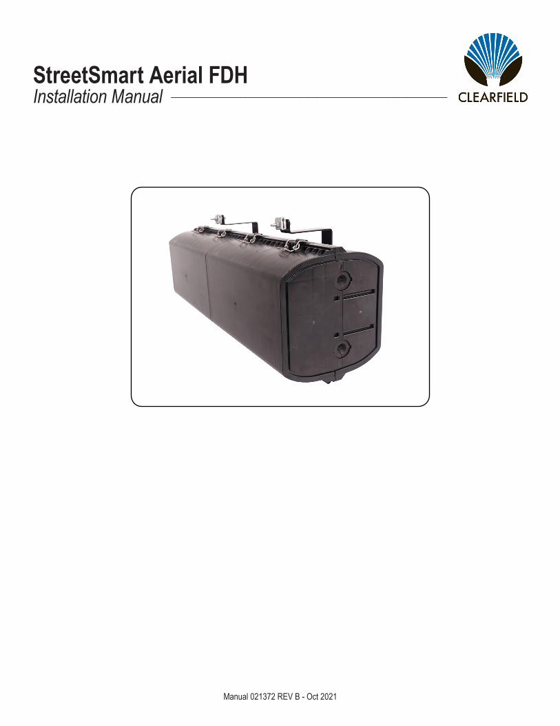
StreetSmart Aerial FDHInstallation Manual ______________________________________________________
Manual 021372 REV B - Oct 2021
Direct: 763.476.6866 • National: 800.422.2537 • www.SeeClearfield.com • [email protected] 2
StreetSmart Aerial FDHInstallation Manual _________________________________________________________
Manual 021372 REV B - Oct 2021
Table of ContentsApplication 3Description 3Technical Specifications 3Components 4Strand Mounting 5Accessing the Aerial FDH 6Layout - 288 7Layout - 144 8Splitter Routing 9Splitter Routing 10Desi Card 13Ice Removal 13Connector Cleaning Procedure 14Standard Warranty 19Proprietary Notice 20Technical Support 20
3
StreetSmart Aerial FDH__________________________________________________________ Installation Manual
Direct: 763.476.6866 • National: 800.422.2537 • www.SeeClearfield.com • [email protected] Manual 021372 REV B - Oct 2021
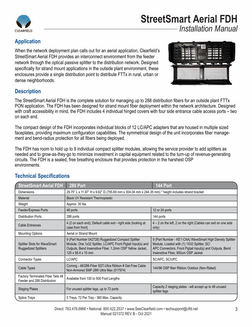
DescriptionThe StreetSmart Aerial FDH is the complete solution for managing up to 288 distribution fibers for an outside plant FTTx PON application. The FDH has been designed for strand mount fiber deployment within the network architecture. Designed with craft accessibility in mind, the FDH includes 4 individual hinged covers with four side entrance cable access ports – two on each end.
The compact design of the FDH incorporates individual blocks of 12 LC/APC adapters that are housed in multiple sized faceplates, providing maximum configuration capabilities. The symmetrical design of the unit incorporates fiber manage-ment and bend-radius protection for all fibers being deployed.
The FDH has room to hold up to 9 individual compact splitter modules, allowing the service provider to add splitters as needed and to grow-as-they-go to minimize investment in capital equipment related to the turn-up of revenue-generating circuits. The FDH is a sealed, free breathing enclosure that provides protection in the harshest OSPenvironments.
ApplicationWhen the network deployment plan calls out for an aerial application, Clearfield’s StreetSmart Aerial FDH provides an interconnect environment from the feeder network through the optical passive splitter to the distribution network. Designed specifically for strand mount applications in the outside plant environment, these enclosures provide a single distribution point to distribute FTTx in rural, urban or dense neighborhoods.
Technical SpecificationsStreetSmart Aerial FDH 288 Port 144 PortDimensions 29.75” L x 11.97” H x 9.62” D (755.65 mm x 304.04 mm x 244.35 mm) * height includes strand bracketMaterial Black UV Resistant ThermoplasticWeight Approx. 30 lbs.Feeder/Express Ports 48 ports 12 or 24 portsDistribution Ports 288 ports 144 ports
Cable Entrances 4 (2 on each end); Default cable exit - right side (looking at case from front)
4 – 2 on the left, 2 on the right (Cables can exit on one side only)
Mounting Options Aerial or Strand Mount
Splitter Slots for WaveSmartRuggedized Splitters
9 (Part Number 042728) Ruggedized Compact Splitter Module, One 1x32 Splitter, LC/APC Front Pigtail Input(s) and Outputs, Bend Insensitive Fiber, 1.2mm OSP Yellow Jacket, 125 x 58.4 x 10 mm
9 (Part Number - KE1-CAA) WaveSmart High Density Splitter Module, Loaded with (1) 1X32 Splitter, SC/APC Connectors, Front Pigtail Input(s) and Outputs, Bend Insensitive Fiber, 900um OSP Jacket
Connector Types LC/APC SC/APC, SC/UPC
Cable Types Corning - 48/288-Fiber SST-Ultra Ribbon # Gel-Free Cable Non-Armored SMF-28® Ultra Max (017974) 144/96 OSP fiber Ribbon Outdoor (Non-Rated)
Factory Terminated Fiber Tails 48 Feeder and 288 Distribution Available from 100 to 500 Foot Lengths
Staging Plates For unused splitter legs, up to 72 ports Capacity 2 staging plates - will accept up to 48 unused splitter legs
Splice Trays 5 Trays, 72 Per Tray - 360 Max. Capacity
Direct: 763.476.6866 • National: 800.422.2537 • www.SeeClearfield.com • [email protected] 4
StreetSmart Aerial FDHInstallation Manual _________________________________________________________
Manual 021372 REV B - Oct 2021
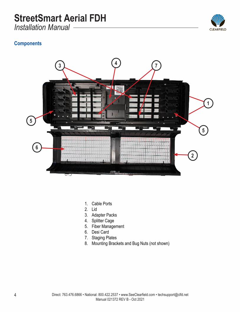
Components
1. Cable Ports2. Lid3. Adapter Packs4. Splitter Cage5. Fiber Management6. Desi Card7. Staging Plates8. Mounting Brackets and Bug Nuts (not shown)
1
2
3 4
5
6
7
5
5
StreetSmart Aerial FDH__________________________________________________________ Installation Manual
Direct: 763.476.6866 • National: 800.422.2537 • www.SeeClearfield.com • [email protected] Manual 021372 REV B - Oct 2021
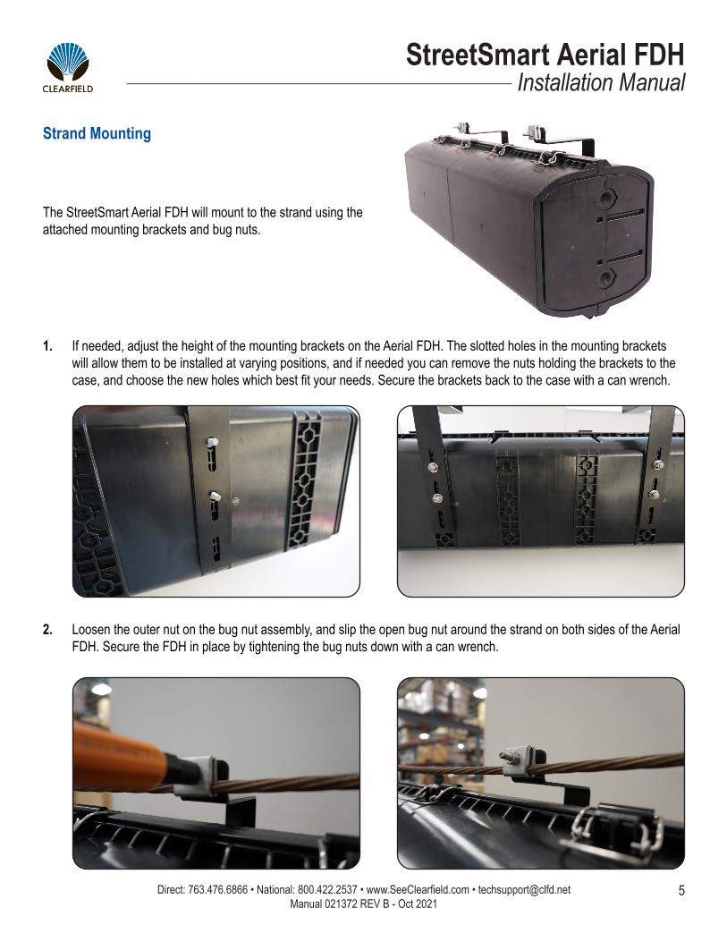
Strand Mounting
The StreetSmart Aerial FDH will mount to the strand using the attached mounting brackets and bug nuts.
Loosen the outer nut on the bug nut assembly, and slip the open bug nut around the strand on both sides of the Aerial FDH. Secure the FDH in place by tightening the bug nuts down with a can wrench.
2.
If needed, adjust the height of the mounting brackets on the Aerial FDH. The slotted holes in the mounting brackets will allow them to be installed at varying positions, and if needed you can remove the nuts holding the brackets to the case, and choose the new holes which best fit your needs. Secure the brackets back to the case with a can wrench.
1.
Direct: 763.476.6866 • National: 800.422.2537 • www.SeeClearfield.com • [email protected] 6
StreetSmart Aerial FDHInstallation Manual _________________________________________________________
Manual 021372 REV B - Oct 2021
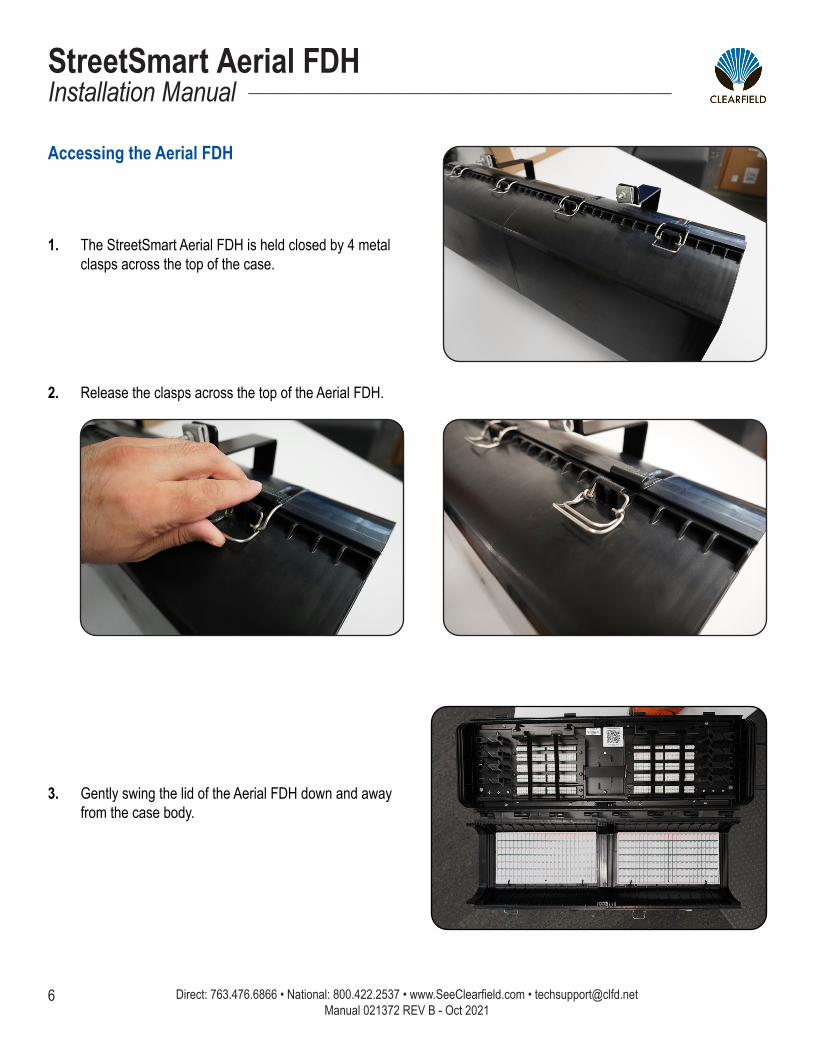
Accessing the Aerial FDH
The StreetSmart Aerial FDH is held closed by 4 metal clasps across the top of the case.
1.
Release the clasps across the top of the Aerial FDH.2.
Gently swing the lid of the Aerial FDH down and away from the case body.
3.
7
StreetSmart Aerial FDH__________________________________________________________ Installation Manual
Direct: 763.476.6866 • National: 800.422.2537 • www.SeeClearfield.com • [email protected] Manual 021372 REV B - Oct 2021
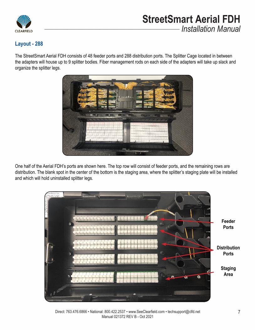
Layout - 288
The StreetSmart Aerial FDH consists of 48 feeder ports and 288 distribution ports. The Splitter Cage located in between the adapters will house up to 9 splitter bodies. Fiber management rods on each side of the adapters will take up slack and organize the splitter legs.
One half of the Aerial FDH’s ports are shown here. The top row will consist of feeder ports, and the remaining rows are distribution. The blank spot in the center of the bottom is the staging area, where the splitter’s staging plate will be installed and which will hold uninstalled splitter legs.
DistributionPorts
StagingArea
FeederPorts
Direct: 763.476.6866 • National: 800.422.2537 • www.SeeClearfield.com • [email protected] 8
StreetSmart Aerial FDHInstallation Manual _________________________________________________________
Manual 021372 REV B - Oct 2021
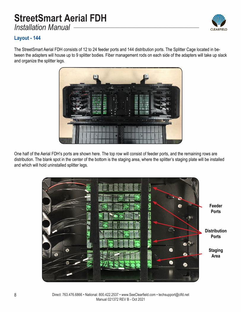
Layout - 144
The StreetSmart Aerial FDH consists of 12 to 24 feeder ports and 144 distribution ports. The Splitter Cage located in be-tween the adapters will house up to 9 splitter bodies. Fiber management rods on each side of the adapters will take up slack and organize the splitter legs.
One half of the Aerial FDH’s ports are shown here. The top row will consist of feeder ports, and the remaining rows are distribution. The blank spot in the center of the bottom is the staging area, where the splitter’s staging plate will be installed and which will hold uninstalled splitter legs.
DistributionPorts
StagingArea
FeederPorts

9
StreetSmart Aerial FDH__________________________________________________________ Installation Manual
Direct: 763.476.6866 • National: 800.422.2537 • www.SeeClearfield.com • [email protected] Manual 021372 REV B - Oct 2021
Splitter Routing
Staging Route Path
Splitter Leg Installation Route Path

Direct: 763.476.6866 • National: 800.422.2537 • www.SeeClearfield.com • [email protected] 10
StreetSmart Aerial FDHInstallation Manual _________________________________________________________
Manual 021372 REV B - Oct 2021
1. To install splitters into the StreetSmart Aerial FDH (288 port), first place the splitter body into the splitter cage. Start with the first splitter body on the left side of the splitter cage.
288 Port
144 Port1. To install splitters into the StreetSmart Aerial FDH (144 port) splitter cage, first hook the lower half of the splitter body
under the 2nd splitter cage rod. Then apply pressure on the upper portion of the splitter body to snap it into place.
11
StreetSmart Aerial FDH__________________________________________________________ Installation Manual
Direct: 763.476.6866 • National: 800.422.2537 • www.SeeClearfield.com • [email protected] Manual 021372 REV B - Oct 2021
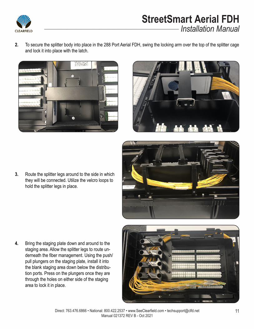
3. Route the splitter legs around to the side in which they will be connected. Utilize the velcro loops to hold the splitter legs in place.
4. Bring the staging plate down and around to the staging area. Allow the splitter legs to route un-derneath the fiber management. Using the push/pull plungers on the staging plate, install it into the blank staging area down below the distribu-tion ports. Press on the plungers once they are through the holes on either side of the staging area to lock it in place.
2. To secure the splitter body into place in the 288 Port Aerial FDH, swing the locking arm over the top of the splitter cage and lock it into place with the latch.

Direct: 763.476.6866 • National: 800.422.2537 • www.SeeClearfield.com • [email protected] 12
StreetSmart Aerial FDHInstallation Manual _________________________________________________________
Manual 021372 REV B - Oct 2021
5. In order to properly take up splitter leg slack inside the Aerial FDH, splitter legs will start underneath the crossbars of the fiber management rods.
9. Route and connect the distribution legs of the splitter as needed.
Note: Always inspect and clean connectors before installing.
Once a proper amount of the slack has been taken up, transition up to above the crossbar of the rods, reversing direction.
Exit the fiber management through one of the gaps in line with the desired port. Always clean and inspect connectors before making a connection to the port.
6.
7.
Route and connect the feeder leg of your splitter.8.
13
StreetSmart Aerial FDH__________________________________________________________ Installation Manual
Direct: 763.476.6866 • National: 800.422.2537 • www.SeeClearfield.com • [email protected] Manual 021372 REV B - Oct 2021
Ice Removal
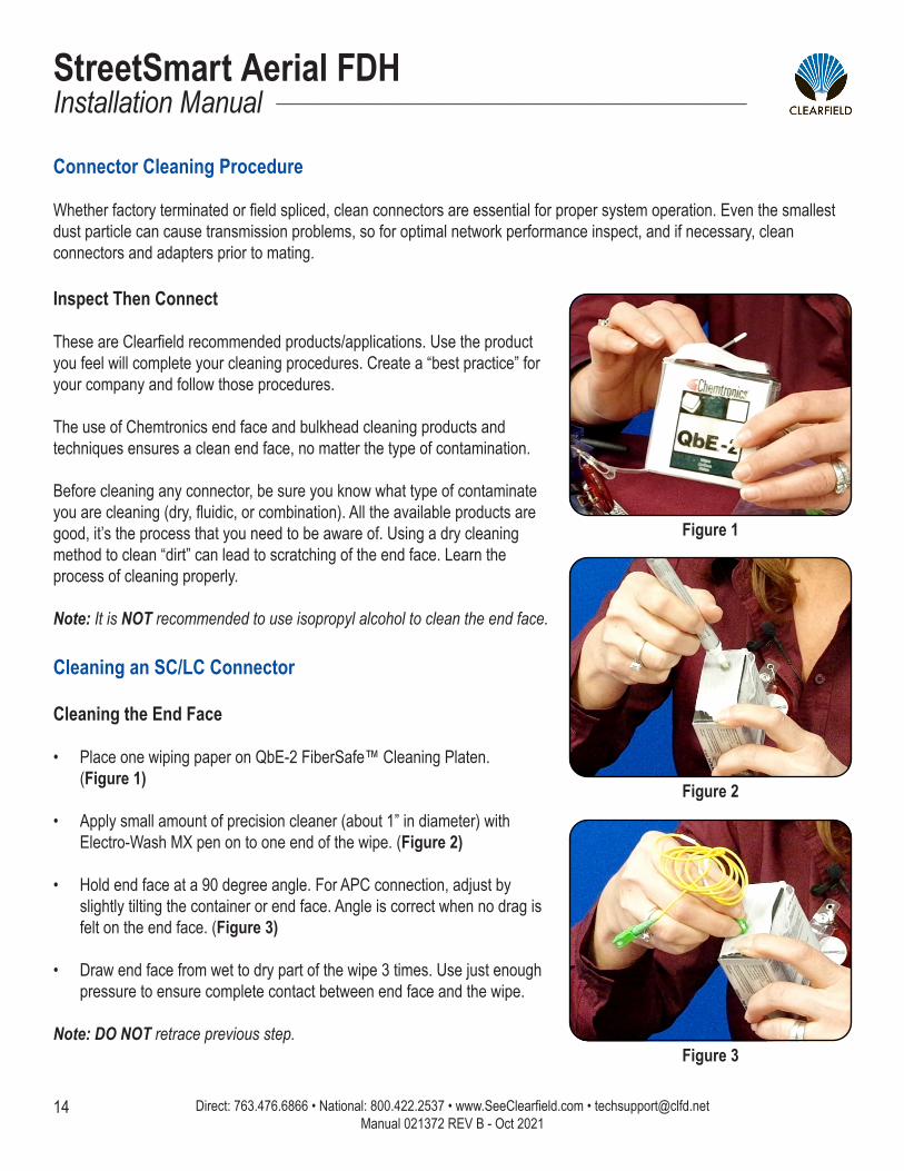
If the Aerial is covered in ice, it will need to be removed to access the interior of the case. In order to remove the ice from the clasps on top of the case holding it closed, use a blunt, non-metallic tool, such as a rubber mallet or back side of a screwdriver. Gently strike the ice until it has broken away from the clasps, allowing the case to be opened.
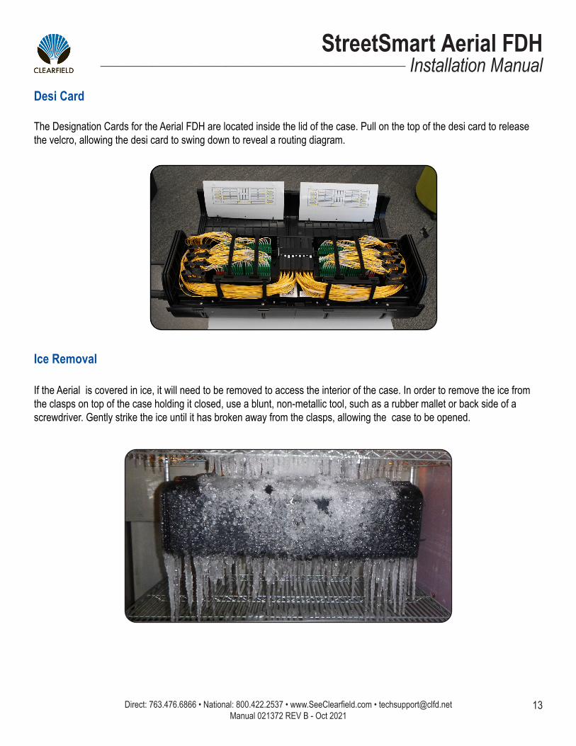
Desi Card
The Designation Cards for the Aerial FDH are located inside the lid of the case. Pull on the top of the desi card to release the velcro, allowing the desi card to swing down to reveal a routing diagram.
Direct: 763.476.6866 • National: 800.422.2537 • www.SeeClearfield.com • [email protected] 14
StreetSmart Aerial FDHInstallation Manual _________________________________________________________
Manual 021372 REV B - Oct 2021
Inspect Then Connect These are Clearfield recommended products/applications. Use the product you feel will complete your cleaning procedures. Create a “best practice” for your company and follow those procedures.
The use of Chemtronics end face and bulkhead cleaning products and techniques ensures a clean end face, no matter the type of contamination.
Before cleaning any connector, be sure you know what type of contaminate you are cleaning (dry, fluidic, or combination). All the available products are good, it’s the process that you need to be aware of. Using a dry cleaning method to clean “dirt” can lead to scratching of the end face. Learn the process of cleaning properly.
Note: It is NOT recommended to use isopropyl alcohol to clean the end face.
Cleaning an SC/LC Connector
Cleaning the End Face
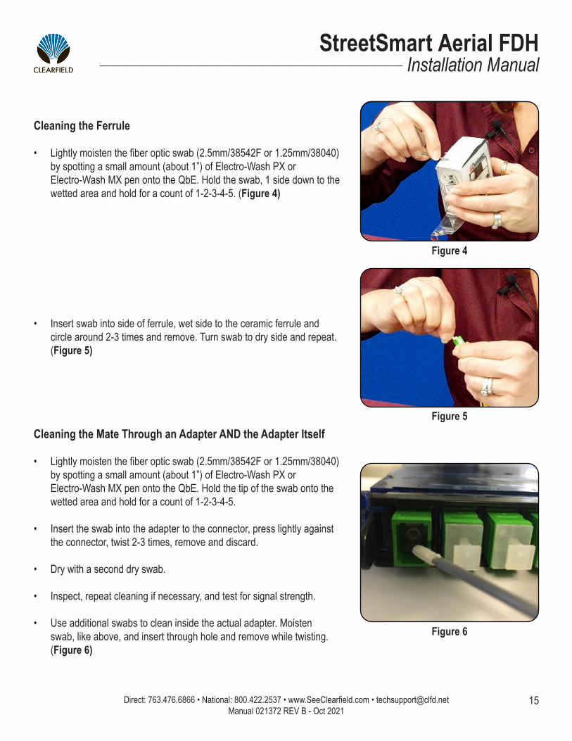
• Place one wiping paper on QbE-2 FiberSafe™ Cleaning Platen. (Figure 1)
• Apply small amount of precision cleaner (about 1” in diameter) with Electro-Wash MX pen on to one end of the wipe. (Figure 2)
• Hold end face at a 90 degree angle. For APC connection, adjust by slightly tilting the container or end face. Angle is correct when no drag is felt on the end face. (Figure 3)
• Draw end face from wet to dry part of the wipe 3 times. Use just enough pressure to ensure complete contact between end face and the wipe.
Note: DO NOT retrace previous step.
Figure 1
Figure 2
Figure 3
Connector Cleaning Procedure
Whether factory terminated or field spliced, clean connectors are essential for proper system operation. Even the smallest dust particle can cause transmission problems, so for optimal network performance inspect, and if necessary, clean connectors and adapters prior to mating.
15
StreetSmart Aerial FDH__________________________________________________________ Installation Manual
Direct: 763.476.6866 • National: 800.422.2537 • www.SeeClearfield.com • [email protected] Manual 021372 REV B - Oct 2021
Cleaning the Ferrule
• Lightly moisten the fiber optic swab (2.5mm/38542F or 1.25mm/38040) by spotting a small amount (about 1”) of Electro-Wash PX or Electro-Wash MX pen onto the QbE. Hold the swab, 1 side down to the wetted area and hold for a count of 1-2-3-4-5. (Figure 4)
Figure 4
Figure 5
Figure 6
Cleaning the Mate Through an Adapter AND the Adapter Itself
• Lightly moisten the fiber optic swab (2.5mm/38542F or 1.25mm/38040) by spotting a small amount (about 1”) of Electro-Wash PX or Electro-Wash MX pen onto the QbE. Hold the tip of the swab onto the wetted area and hold for a count of 1-2-3-4-5.
• Insert the swab into the adapter to the connector, press lightly against the connector, twist 2-3 times, remove and discard.
• Dry with a second dry swab.
• Inspect, repeat cleaning if necessary, and test for signal strength.
• Use additional swabs to clean inside the actual adapter. Moisten swab, like above, and insert through hole and remove while twisting. (Figure 6)
• Insert swab into side of ferrule, wet side to the ceramic ferrule and circle around 2-3 times and remove. Turn swab to dry side and repeat. (Figure 5)
Direct: 763.476.6866 • National: 800.422.2537 • www.SeeClearfield.com • [email protected] 16
StreetSmart Aerial FDHInstallation Manual _________________________________________________________
Manual 021372 REV B - Oct 2021
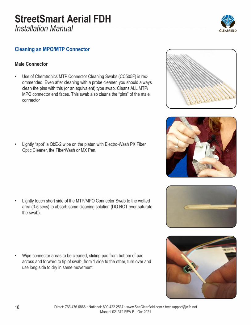
Male Connector
• Use of Chemtronics MTP Connector Cleaning Swabs (CC505F) is rec-ommended. Even after cleaning with a probe cleaner, you should always clean the pins with this (or an equivalent) type swab. Cleans ALL MTP/MPO connector end faces. This swab also cleans the “pins” of the male connector
• Lightly “spot” a QbE-2 wipe on the platen with Electro-Wash PX Fiber Optic Cleaner, the FiberWash or MX Pen.
• Lightly touch short side of the MTP/MPO Connector Swab to the wetted area (3-5 secs) to absorb some cleaning solution (DO NOT over saturate the swab).
• Wipe connector areas to be cleaned, sliding pad from bottom of pad across and forward to tip of swab, from 1 side to the other, turn over and use long side to dry in same movement.
Cleaning an MPO/MTP Connector
17
StreetSmart Aerial FDH__________________________________________________________ Installation Manual
Direct: 763.476.6866 • National: 800.422.2537 • www.SeeClearfield.com • [email protected] Manual 021372 REV B - Oct 2021
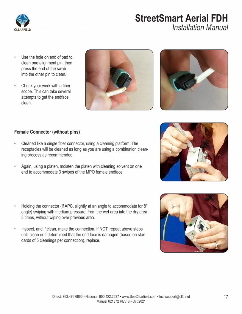
• Use the hole on end of pad to clean one alignment pin, then press the end of the swab into the other pin to clean.
• Check your work with a fiber scope. This can take several attempts to get the endface clean.
Female Connector (without pins)
• Cleaned like a single fiber connector, using a cleaning platform. The receptacles will be cleaned as long as you are using a combination clean-ing process as recommended.
• Again, using a platen, moisten the platen with cleaning solvent on one end to accommodate 3 swipes of the MPO female endface.
• Holding the connector (If APC, slightly at an angle to accommodate for 8° angle) swiping with medium pressure, from the wet area into the dry area 3 times, without wiping over previous area.
• Inspect, and if clean, make the connection. If NOT, repeat above steps until clean or if determined that the end face is damaged (based on stan-dards of 5 cleanings per connection), replace.
Direct: 763.476.6866 • National: 800.422.2537 • www.SeeClearfield.com • [email protected] 18
StreetSmart Aerial FDHInstallation Manual _________________________________________________________
Manual 021372 REV B - Oct 2021
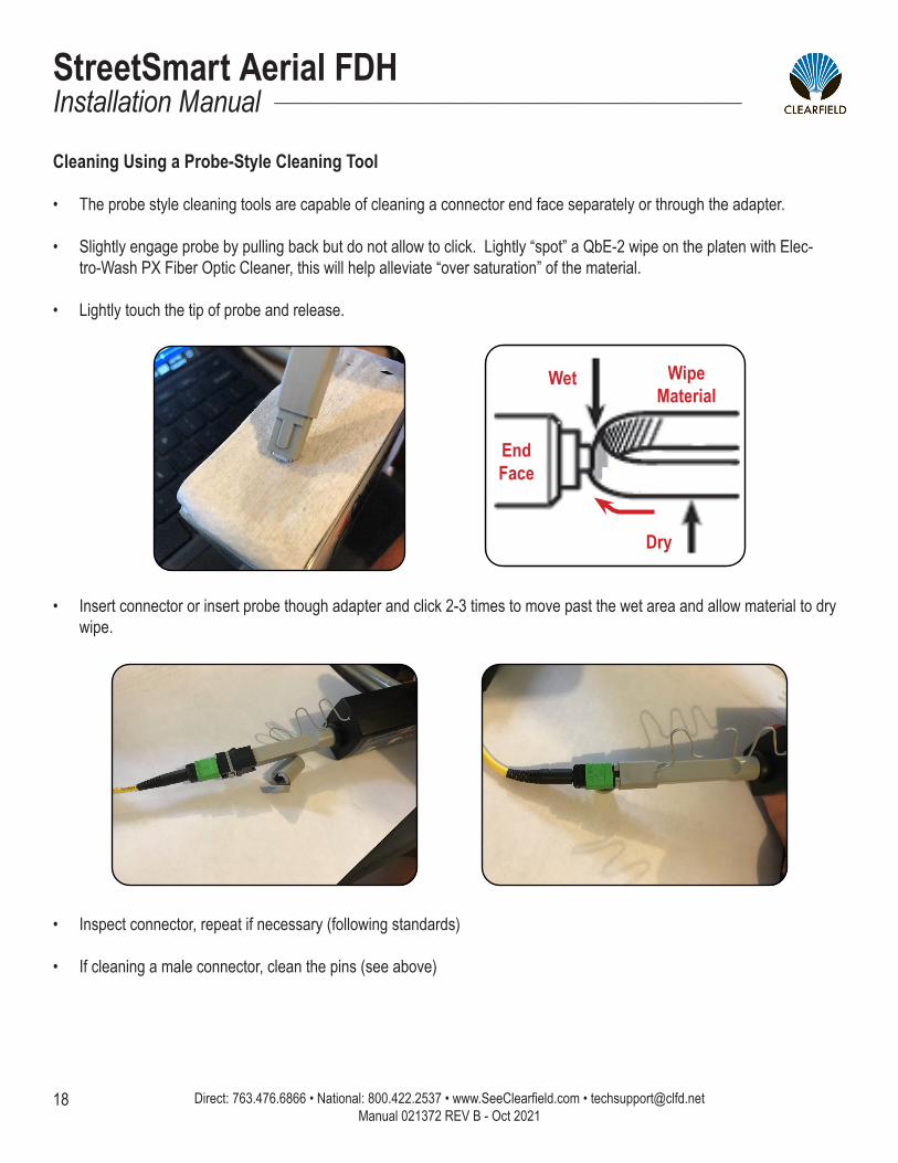
Cleaning Using a Probe-Style Cleaning Tool
• The probe style cleaning tools are capable of cleaning a connector end face separately or through the adapter.
• Slightly engage probe by pulling back but do not allow to click. Lightly “spot” a QbE-2 wipe on the platen with Elec-tro-Wash PX Fiber Optic Cleaner, this will help alleviate “over saturation” of the material.
• Lightly touch the tip of probe and release.
WipeMaterial
Wet
EndFace
Dry
• Insert connector or insert probe though adapter and click 2-3 times to move past the wet area and allow material to dry wipe.
• Inspect connector, repeat if necessary (following standards)
• If cleaning a male connector, clean the pins (see above)
19
StreetSmart Aerial FDH__________________________________________________________ Installation Manual
Direct: 763.476.6866 • National: 800.422.2537 • www.SeeClearfield.com • [email protected] Manual 021372 REV B - Oct 2021
Standard WarrantyClearfield warrants to the original purchaser of the Product sold hereunder is free from defects in material and workmanship under normal use and service, subject to exceptions stated herein. Product purchased is warranted as follows: Clearfield designed and branded Products are warranted for three (3) years: Products manufactured by Clearfield to customer prints and/or specifications are warranted for one (1) year; and any Product Clear-field acquires from or through a third-party manufacturer or distributor and resells to Customer as the original customer will carry the manufacturer’s pass-through warranty, if any. In all cases, the warranty period commences on the date of shipment to the original purchaser.
Warranty Claim Procedure
If any Product purchased from Clearfield is found defective under the above warranty, the following basic procedure must be followed:
1. Customer must contact Clearfield and obtain a Return Materials Authorization2. Following authorization, the Customer ships the product-freight collect-to Clearfield’s manufacturing facility3. Clearfield shall repair or replace the defective Product at its sole option and discretion, and return the repaired or replacement Product to Cus-
tomer’s site, freight prepaid
Note: If the Product is not found to be defective by Clearfield, the product will be returned to the Customer and the customer billed for freight in both directions.
View our warranty policy here: https://www.seeclearfield.com/warranty.html
Limitations of Warranty
Correction of defects by repair or replacement, at the option of Clearfield Inc, shall constitute the exclusive sole remedy for a breach of this limited warranty. Clearfield shall not be liable under any circumstances for any special, consequential, incidental, punitive, or exemplary damages arising out of or in any way connected with the product or with agreement to sell product to buyer, including, but not limited to damages for lost profits, loss of use, or for any damages or sums paid by buyer to third parties. The foregoing limitation of liability shall apply whether the claim is based upon principles of contract, warranty, negligence or other tort, breach of statutory duty, principles of indemnity or contribution, the failure of any limited or exclusive remedy to achieve its essential purpose, or otherwise.
Clearfield will not be responsible for any labor or materials costs associated with installation or incorporation of Clearfield products at customer sites, including any costs of alteration, replacement or defective product, or any field repairs.
Other Limitations
Clearfield assumes no warranty liability regarding defects caused by:
1. Customer’s modification of Product, excepting installation activities described in Clearfield documentation2. Customer re-packaging of Product for shipment to third parties or destinations other than those originally shipped to by Clearfield, or any de-
fects suffered during shipping where the Product has been re-packaged3. Customer’s installation or maintenance, excepting activities described in and performed in accordance with Clearfield documentation4. Customer’s improper or negligent use or application of Product5. Other causes external to the Product, including but not limited to accidents, catastrophe, acts of God, government action, war, riot, strikes, civil
commotion, sovereign conduct, or the acts or conduct of any person or persons not party to or associated with Clearfield6. Environmental factors and weathering resulting in aging and damage not necessary or applicable to the function of the product
Direct: 763.476.6866 • National: 800.422.2537 • www.SeeClearfield.com • [email protected] 20
StreetSmart Aerial FDHInstallation Manual _________________________________________________________
Manual 021372 REV B - Oct 2021
Proprietary Notice
Information contained in this document is copyrighted by Clearfield, Inc. and may not be duplicated in full or part by any person without prior written approval of Clearfield, Inc.
Its purpose is to provide the user with adequately detailed documentation to efficiently install the equipment supplied. Every effort has been made to keep the information contained in this document current and accurate as of the date of publication or revision.
However, no guarantee is given or implied that the document is error free or that it is accurate with regard to any specification.
Technical Support
Clearfield, Inc. can be contacted for any issues that arise with the supplied product.
If you need to return the supplied product, you must contact the Clearfield, Inc. Customer Service Department to request a Returned Materials Authorization (RMA) number.
Clearfield, Inc.7050 Winnetka Ave NMinneapolis, MN 55428
Toll Free: 800.422.2537Phone: 763.476.6866Fax: 763.475.8457
Customer Support: [email protected] Support: [email protected]