steps for selecting the proper buck-boost … for selecting the proper buck-boost transformer ......
TRANSCRIPT
Acme Electric Corporation
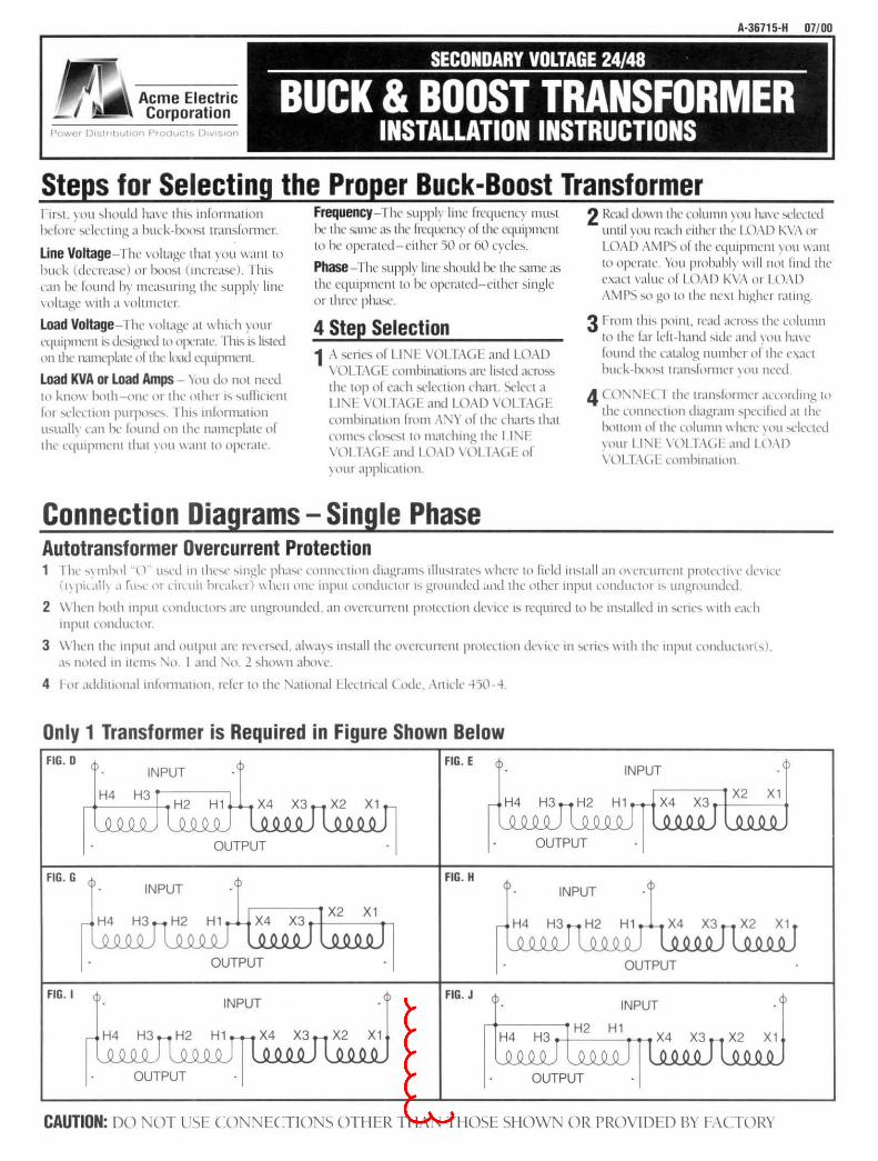
Steps for Selecting the Proper Buck-Boost Transformer Fir'>t, you '>hnuld hm e thi~ mfonnation bdm-c .,clecung a buck-boo'>t transfom1er.
Line Voltage- ! he' oltage that you want to buck (decrea'>e) or boo<,t (lnt:re<l'>e). This can he lound h)' meac,uring the <;uppl)' line 'oltage " 1th a 'oltmeter.
load Voltage- I he ,·oltage at "hich your cqu1pment L'> dc~1gncd to operate. Thi>. i!. listed on the namcpbtc of the load L't)Uipmmt.
load KVA or load Amps - 'tou do not need to kno\\ hot h-one or the nt her I'> 'ou1Tic1ent lor '>dn:uon purpo-.c-.. l lu.., mlornl<llion u.,ualh L,lll he lound on the nameplate of the equ1pment tll<lt \'llU "ant to operate.
Frequency- 1 he !>upply line frequency must be the ~une a~ the frcquenL)' of the equipmem to he operated-either 50 or 60 C)'eb.
Phase- The c,upply line ~hould be the same as the equipment to be operated-either single or three pha!>c.
4 Step Selection 1 A '>cnc~ ol L I l \'l)L rAG I: and LOAD
\ 'OL l . \G [ combmation'> arc listed aero§ the top of each '>election chan. Select a L 1'-<L· \01 J,\(,[ and LOAD \ 'OLT.\GE combmauon I rom A. 't of the chans that come<, do.,c-.t to matchmg the L 1:'\E \'OLl \(,[ and I(.),\)) \01 Tr\(,E of \ OUI ,tppltGllllln.
Connection Diagrams- Single Phase Autotransformer Overcurrent Protection
2 Read do" n the column you hmc '>elected unul rou reach euhcr the IOr\D K\'. \ or LOAD t\MP', of the eqwpment \'Oll want to operate. You probahl)' " ill not find the exact value of I OAD KVt\ or LOAD AMP') '>ll go to the ne't higher rating.
3 I-rom thl'> pomt. read acro'>s the column to the lar !cit-hand '>Ide and \'Oll ha\'e lound the catalog number of the e\act buck-bno'>l tran ... lonnrr 'ou need.
4 ((.)'\'-< I ( I the tran.,formcr accnrdmg tn the connection l.lt,tgram -.pccilted at the hottom of the column" here \nu '>Cicllcd YOUr l I I \'l)( 1.\(, ( and I 0.\D \'OL 1.\C.J combmat1nn.
1 I he ..,, mbnl " t) tN'd Ill thc ... e -.mglc pluo.,c conm•ct1nn diagranl'> illu'>tratc-. \\'here to field in'>tall <Ill m c1ntnent prottTtl\ c tin 1cc ( t, pil.tlh ,1 fthl 111 L ill uit brcakc1) "hen nne inputumductol h grounded and the other input condul'lnr 1~ ungrounded.
2 \\hen both 1nput condttLtor'> arc ungrounded. an 0\ crcurrent protectton de' 1cc I'> required to he lll'>tallcd 1n -.eric-." nh cad1 mput conductot.
3 \\hen the mput and output arc re,ers<'d, alway'> lll'>tall the mcrcunent protccuon de,·ice in '>l'lle'> \\llh the mput conduetnrh). <1'> noted 111 Ill.' Ill'> \.o I and '\n. 2 sho" n ahm e
4 I or <lddtl lonal mlnnnat1on, rclcr to the '\atton,tl Llcctru:al C.. ode .. \1ttclc 450-4.
Only 1 Transformer is Required in Figure Shown Below FIG. D FIG . E
OUTPUT OUTPUT
FIG. G FIG. H INPUT
OUTPUT
FIG . I FIG. J
OUTPUT OUTPUT
CAUTION: DO OT U~C CON ECTIO S OTIIER TIIA TI IOSE 51 IOWN OR PROVIDED BY f ACTORY
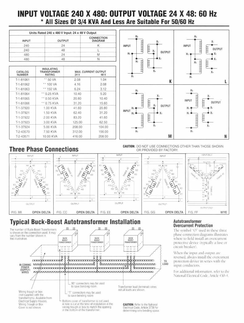
INPUT VOLTAGE 240 X 480: OUTPUT VOLTAGE 24 X 48: 60 Hz * All Sizes Of 3/4 KVA And Less Are Suitable For 50/60Hz
Units Rated 240 x 480 V Input: 24 x 48 V Output
CONNECTION INPUT OUTPUT DIAGRAM
240 24 K
240 48 L 480 24 M
480 48 N
INSULATING CATALOG TRANSFORMER MAX. CURRENT OUTPUT NUMBER RATING 24 v 48 v
T-1·81061 ··50 VA 2.08 1.04
T-1-81062 •• 100VA 4.16 2.08
T-1·81063 •• 150VA 6.24 3. 12
T-1 -81064 •• 0.25 KVA 10.40 5.20
T-1 -81065 .• 0.50 KVA 20.80 10.40
T- 1-81066 •• 0.75 KVA 31.20 15.60
T- 1-37920 1.00 KVA 41 .60 20.80
T-1-37921 1.50 KVA 62.40 31.20
T- 1-37922 2.00 KVA 83.20 41.60
T-1 -37923 3.00 KVA 125.00 62.50
T-1 -37924 5.00 KVA 208.00 104.00
T-2-43570 7.50 KVA 312.00 156.00
T-2-43571 10.00 KVA 416.00 208.00
Three Phase Connections
FIG. BB OPEN DELTA FIG CC OPEN DELTA FIG EE
H, H,
x,
~UTPUT x. x.
K
H• H•
x,
OUTPUT
x,
x. x.
M
CAUTION: DO NOT USE CONNECTIONS OTHER THAN THOSE SHOWN OR PROVIDED BY FACTORY.
OUTPUT O'lLY
L
N
OPEN DELTA FIG. GG OPEN DELTA FIG. FF WYE
Typical Buck-Boost Autotransformer Installation Autotransformer Overcurrent Protection
ck-8oost Translormers / onnectiOn used It may
The number of Bu IS shown on the c vary from the nun thiS tllustratton
1ber shown 10
101 101 101 101
~ / (6
IN COMIN POWER
(SUPPLY WIRES
/ t I
G
I
/1 I
ugh or box lied wtth the
Wtnng tro (not supp transform ers) Available from Electncal Supply Houses Wtnng Trough or Box Cover IS not shovm
BUCK BUCK BOOST BOOST
TRANSFORMER ' '
TRANSFORMER ' '
-, r n .., r
/ - , r n '"' r
/ tl II I I II II II
II II II II II II
1:! H 1>1
~ bl
'- 90 connectors may be used to save bendmg room
'- T connectors may be used to save bendmg room
Bottom cover of transformer 1s not used A hole ts cut at the l tme of tnstallatlon tn the v11nng trough or box to match the opemng m the bottom of the transformer.
101 101
/ ~ BUCK
BOOST TRANSFORMER
' ' -. r n.., r v / I I II II
II I I II
...
/ Transformer lead (term mal) w1res not all leads are shown
CAUTION: Refer to the NatiOnal Electncal Code. Arttcle 3736 for determtmng w1re bendtng space.
TO LOAD
The"' mho I .. 0 .. tN'U 111 thl''>l' three pha-.e connect ion diagram'> lllu-.tratc-. " here to held liN all an m crcurrcnt protrcun· dn ICC ( t\ ptralh a ltN' or rnnut hreakcrl
\\ hen the tnput and t1tttput .trc IT\Tt'>Cd. aJmt\''> in'>talithc tl\UClliTL'nl protection dn tee in -.eric'> "11 h the 1nput cnnductor~.
I or addlllnnal mlnnn.ninn. rclcr Ill thr '-<tllnn,tl llrcllical (ode. , \ ntrlc +50--+
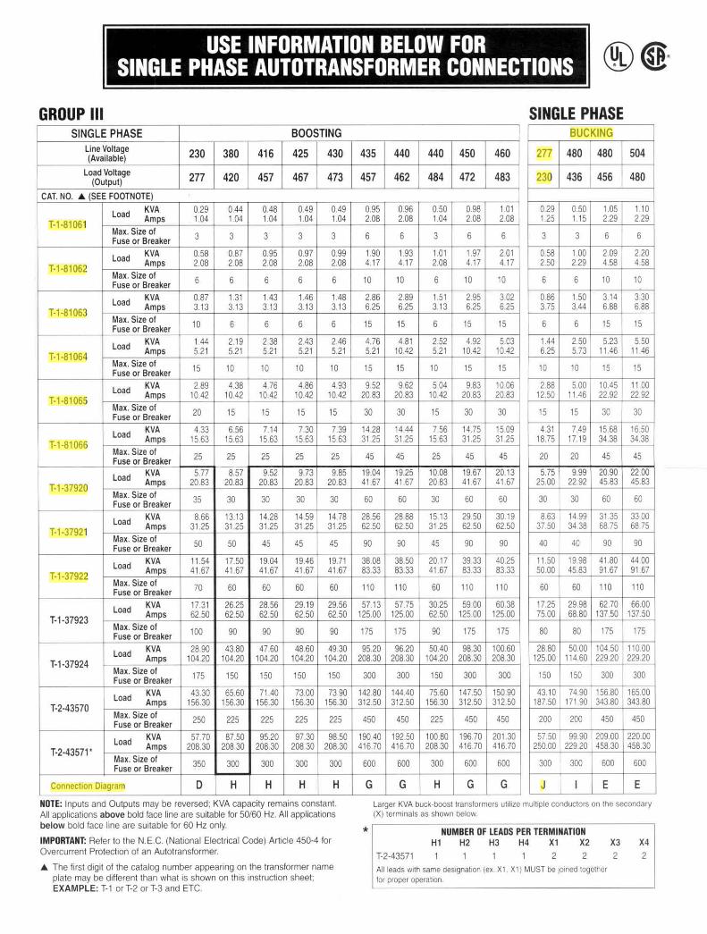
USE INFORMATION BELOW FOR SINGLE PHASE AUTOTRANSFORMER CONNECTIONS
GROUP Ill SINGLE PHASE BOOSTING
line Voltage 230 380 416 425 430 (Available)
Load Voltage 277 420 457 467 473 (Output)
CAT. NO . .A. (SEE FOOTNOTE)
Load KVA 0.29 0.44 0.48 0.49 0.49
T-1-81061 Amps 1.04 1 04 1.04 1.04 1.04
Max. Size of 3 3 3 3 3 Fuse or Breaker
Load KVA 0.58 0.87 0.95 0.97 0.99
T-1-81062 Amps 2.08 2.08 2.08 2.08 2.08
Max. Size of Fuse or Breaker 6 6 6 6 6
Load KVA 0.87 1.31 1.43 1.46 1.48
T-1-81063 Amps 3. 13 3.13 3.13 3.13 3.13
Max. Size of Fuse or Breaker 10 6 6 6 6
Load KVA 1.44 2.19 2.38 2.43 2.46
T-1-81064 Amps 5.21 5.21 5.21 5.21 5.21 Max. Size of 15 10 10 10 10 Fuse or Breaker
Load KVA 2.89 4.38 4.76 4.86 4.93
T-1-81065 Amps 10.42 10.42 10.42 10.42 10.42 Max. Size of Fuse or Breaker 20 15 15 15 15
Load KVA 4.33 6.56 7.14 7.30 7.39
T-1-81066 Amps 15.63 15.63 15.63 15.63 15.63
Max. Size of 25 25 25 25 25 Fuse or Breaker
Load KVA 5.77 8.57 9.52 9.73 9.85
T-1 -37920 Amps 20.83 20.83 20.83 20.83 2083 Max. Size of 35 30 30 30 30 Fuse or Breaker
Load KVA 8.66 13.13 14.28 14.59 14.78
T-1-37921 Amps 31 .25 31.25 31.25 31 .25 31.25
Max. Size of Fuse or Breaker 50 50 45 45 45
Load KVA 11 .54 17.50 19.04 19.46 19.71
T-1-37922 Amps 41 .67 41 .67 41 .67 41 .67 41 .67 Max. Size of 70 60 60 60 60 Fuse or Breaker
Load KVA 17.31 26.25 28.56 29.19 29.56 Amps 62.50 62.50 62.50 62.50 62.50
T-1 -37923 Max. Size of Fuse or Breaker 100 90 90 90 90
Load KVA 28.90 43.80 47 60 48.60 49.30
T-1-37924 Amps 104.20 104.20 104.20 104.20 104.20 Max. Size of 175 150 150 150 150 Fuse or Breaker
Load KVA 43.30 65.60 71.40 73.00 73.90
T-2-43570 Amps 156.30 156.30 156.30 156.30 156.30
Max. Size of 250 225 225 225 225 Fuse or Breaker
Load KVA 57.70 87.50 95.20 97.30 98.50
T-2-43571' Amps 208.30 208.30 208.30 208.30 208.30
Max. Size of 350 300 300 300 300 Fuse or Breaker
Connection Diagram D H H H H
NOTE: Inputs and Outputs may be reversed; KVA capacity remains constant. All applications above bold face line are suitable for 50/60 Hz. All applications below bold face line are suitable for 60 Hz only.
IMPORTANT: Refer to the N.E.C. (National Electrical Code) Article 450-4 for Overcurrent Protection of an Autotransformer.
.A. The first digit of the catalog number appearing on the transformer name plate may be different than what is shown on this instruction sheet; EXAMPLE: T-1 or T-2 or T-3 and ETC.
SINGLE PHASE BUCKING
435 440 440 450 460 277 480 480 504
457 462 484 472 483 230 436 456 480
0.95 0.96 0.50 0.98 1 01 0.29 0.50 1.05 1.10 2.08 2.08 1.04 2.08 2.08 1.25 1.15 2.29 2.29
6 6 3 6 6 3 3 6 6
1.90 1.93 1.01 1.97 2.01 0.58 1.00 2.09 2.20 4.17 4.17 2.08 4.17 4.17 2.50 2.29 4.58 4.58
10 10 6 10 10 6 6 10 10
2.86 2.89 1.51 2.95 3.02 0.86 1.50 3.14 3.30 6.25 6.25 3.13 625 6.25 3.75 3.44 6.88 6.88
15 15 6 15 15 6 6 15 15
4.76 4.81 2.52 4.92 5.03 1.44 2.50 5.23 5.50 5.21 10.42 5.21 10.42 10 42 6.25 5.73 11 .46 11.46
15 15 10 15 15 10 10 15 15
952 9.62 5.04 9.83 10.06 2.88 5.00 10.45 11.00 20.83 2083 10.42 20.83 20.83 12.50 11.46 22.92 22.92
30 30 15 30 30 15 15 30 30
14.28 14.44 7.56 14.75 15.09 4.31 7.49 15.68 16.50 31.25 31.25 15.63 31.25 31.25 18.75 17.19 34.38 34.38
45 45 25 45 45 20 20 45 45
19.04 19.25 10.08 19.67 20.13 5.75 9.99 20.90 22.00 41 .67 41 .67 20.83 41 .67 41 .67 25.00 22.92 45.83 45.83
60 60 30 60 60 30 30 60 60
28.56 28.88 15.13 29.50 3019 863 14.99 31.35 33.00 62.50 62.50 31.25 62.50 62.50 37.50 34.38 68.75 68 75
90 90 45 90 90 40 40 90 90
38.08 38.50 20.17 39.33 40.25 11.50 19.98 41.80 44.00 83.33 83.33 41.67 83.33 83.33 50.00 45.83 91.67 91.67
110 110 60 110 110 60 60 11 0 110
57.13 57.75 30.25 5900 60.38 17.25 29.98 62.70 66.00 125.00 125.00 62.50 125.00 125.00 75.00 68.80 137.50 137.50
175 175 90 175 175 80 80 175 175
95.20 96.20 50.40 98.30 100.60 28.80 50.00 104.50 110.00 208.30 208.30 104.20 208.30 208.30 125.00 114.60 229.20 22920
300 300 150 300 300 150 150 300 300
142.80 144.40 75.60 147.50 150.90 43.10 74.90 156.80 165.00 312.50 312.50 156.30 312.50 312.50 187.50 171 .90 343.80 343.80
450 450 225 450 450 200 200 450 450
190.40 192.50 100.80 196.70 201 .30 57.50 99.90 209.00 220.00 416.70 416.70 208.30 416.70 416.70 250.00 229.20 45830 45830
600 600 300 600 600 300 300 600 600
G G H G G J I E E
Larger KVA buck-boost transformers ut1hze multiple conductors on the secondary (X) term1nals as shown below.
* NUMBER OF LEADS PER TERMINATION H1 H2 H3 H4 X1 X2
T-2·43571 2 2 All leads w1th same des1gnahon (ex X1 . X1 ) MUST be 1omed together for proper operat1on.
X3
2
X4
2
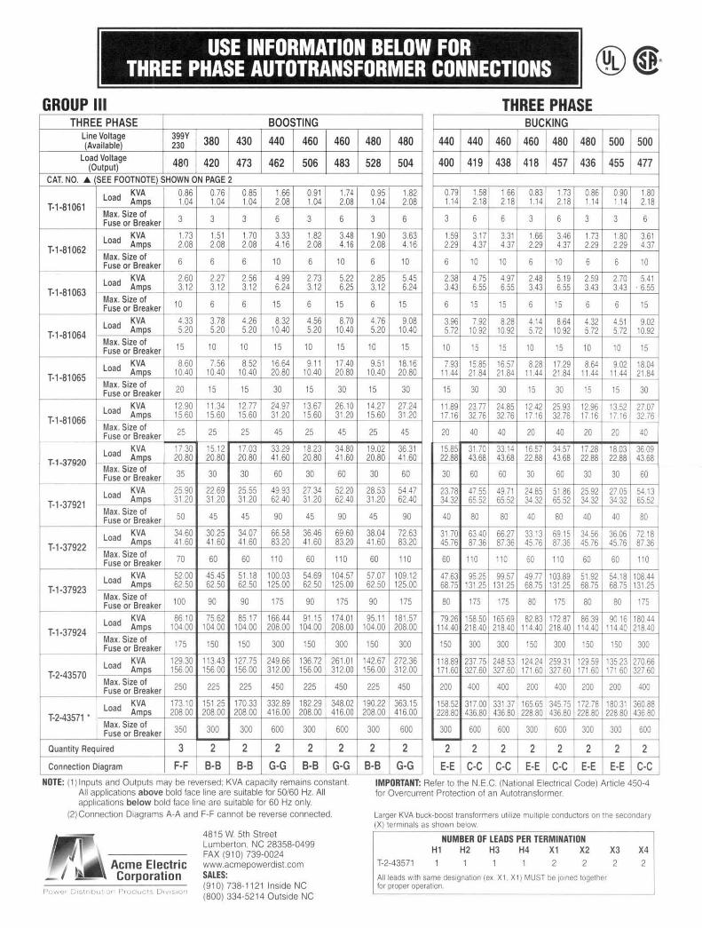
USE INFORMATION BELOW F THREE PHASE AUTOTRANSFORMER C
R NNECTIONS
GROUP Ill THREE PHASE BOOSTING
line Voltage 399Y 380 430 440 460 460 (Available) 230 Load Voltage 480 420 473 462 506 483 (Output)
CAT. NO . ..t. (SEE FOOTNOTE) SHOWN ON PAGE 2
Load KVA 0.86 0.76 0.85 1.66 0.91 1.74 Amps 1.04 1.04 1.04 2.08 1.04 2.08 T-1-81061
Max. Size of Fuse or Breaker 3 3 3 6 3 6
Load KVA 1.73 1.51 1.70 3.33 1.82 3.48 Amps 2.08 2.08 208 4.16 2.08 4.16 T-1-81062
Max. Size of Fuse or Breaker 6 6 6 10 6 10
Load KVA 2.60 2.27 2.56 4.99 2.73 5.22 Amps 3.12 312 3.12 6.24 3.12 6.25 T-1-81063
Max. Size of Fuse or Breaker 10 6 6 15 6 15
Load KVA 4.33 3.78 4.26 8.32 4.56 8.70 Amps 5.20 5.20 5.20 10.40 5.20 10.40 T-1-81064
Max. Size of Fuse or Breaker 15 10 10 15 10 15
Load KVA 8.60 7.56 8.52 16.64 9.11 17.40 Amps 10.40 10.40 10.40 20.80 10.40 20.80 T-1-81065
Max. Size of Fuse or Breaker 20 15 15 30 15 30
Load KVA 1290 11.34 12.77 24.97 13.67 2610 Amps 15.60 15.60 15.60 31.20 15.60 31.20 T-1-81066
Max. Size of Fuse or Breaker 25 25 25 45 25 45
Load KVA 17 30 15.12 17.03 33.29 18.23 34.80 Amps 20.80 20.80 20.80 41.60 20.80 41 .60 T-1-37920
Max. Size of Fuse or Breaker 35 30 30 60 30 60
Load KVA 25.90 22.69 25.55 49.93 27.34 52.20 Amps 31 20 31 20 31.20 62.40 31 20 62 40 T-1-37921
Max. Size of Fuse or Breaker 50 45 45 90 45 90
Load KVA 34.60 30.25 34.07 66.58 36.46 69.60 Amps 41 60 41.60 41 60 83.20 41.60 83.20 T-1-37922
Max. Size of Fuse or Breaker 70 60 60 110 60 110
Load KVA 52.00 45 45 51.18 100.03 54.69 104.57 Amps 62.50 62.50 62.50 125.00 62.50 125.00 T-1-37923
Max. Size of Fuse or Breaker 100 90 90 175 90 175
Load KVA 8610 75.62 85.17 166.44 91.15 174.01 Amps 104.00 104.00 104.00 208.00 104.00 208.00 T-1-37924
Max. Size of Fuse or Breaker 175 150 150 300 150 300
Load KVA 129.30 113.43 127.75 249.66 136.72 261.01 Amps 156.00 156.00 156.00 312.00 156.00 312.00 T-2-43570
Max. Size of Fuse or Breaker 250 225 225 450 225 450
Load KVA 173.10 151 25 170.33 332.89 182.29 348.02 Amps 208.00 208.00 208.00 416.00 208.00 416.00 T-2-43571 '
Max. Size of Fuse or Breaker 350 300 300 600 300 600
Quantity Required 3 2 2 2 2 2
Connection Diagram F-F 8-B B-B G-G 8-B G-G NOTE: (1) 1nputs and Outputs may be reversed: KVA capac1ty remains constant.
All applications above bold face line are suitable for 50/60 Hz. All applications below bold face line are suitable for 60 Hz only.
(2) Connect1on D1agrams A-A and F-F cannot be reverse connected.
4815 W. 5th Street Lumberton, NC 28358-0499 FAX (91 0) 739-0024 www.acmepowerd1st.com SALES: (910) 738-11211nside NC (800) 334-5214 Outside NC
THREE PHASE BUCKING
480 480 440 440 460 460 480 480 500 500
528 504 400 419 438 418 457 436 455 477
0.95 1.82 0 79 1.58 1.66 0.83 173 0.86 0.90 1.80 1.04 2.08 1.14 2.18 2.18 1.14 2.18 I 14 1.14 2.18
3 6 3 6 6 3 6 3 3 6
1.90 3.63 1.59 317 331 1.66 346 1 73 1.80 3.61 2.08 4.16 2.29 4 37 4.37 2.29 4 37 2 29 2.29 4.37
6 10 6 10 10 6 10 6 6 10
2.85 5.45 2.38 4 75 4.97 2 48 519 2 59 2.70 5.41 3.12 6.24 343 6.55 6.55 343 6.55 343 3.43 . 6.55
6 15 6 15 15 6 15 6 6 15
4.76 9.08 3.96 7.92 828 4 14 8.64 4.32 4 51 9.02 5.20 10.40 572 10.92 10.92 5.72 10.92 572 572 10.92
10 15 10 15 15 10 15 10 10 15
9.51 18.16 7.93 15 85 16 57 8 28 17 29 864 902 18.04 10.40 20.80 1144 2184 21.84 11 44 21 84 11 44 11 44 21.84
15 30 15 30 30 15 30 15 15 30
14.27 27.24 11.89 23.77 24.85 1242 25.93 12.96 13.52 27.07 15.60 31.20 17.16 32.76 32.76 1716 3276 17 16 17 16 32 76
25 45 20 40 40 20 40 20 20 40
19 02 36.31 15 85 31.70 3314 16.57 34 57 17 28 1803 3609 20.80 41.60 22.88 43.68 43.68 22.88 43.68 2288 22.88 43.68
30 60 30 60 60 30 60 30 30 60
28.53 54 47 23 78 47.55 49.71 24 85 51 86 25.92 27.05 5413 31.20 62.40 34 32 65.52 65.52 34 32 65.52 34.32 3432 65.52
45 90 40 80 80 40 80 40 40 80
38.04 72.63 3170 63 40 6627 33 13 6915 34 56 3606 72.18 41.60 83.20 4576 87.36 87.36 4576 87.36 4576 45.76 87.36
60 110 60 110 110 60 110 60 60 110
57.07 109.12 47 63 95 25 9957 49.77 103.89 51.92 5418 10844 62.50 125.00 6875 13125 13125 68.75 131.25 68.75 68.75 131 25
90 175 80 175 175 80 175 80 80 175
95.11 181.57 79 26 158.50 165.69 82 83 172 87 8639 90 16 18044 104.00 208.00 114 40 218 40 218.40 114 40 21840 114 40 11440 21840
150 300 150 300 300 150 300 150 150 300
142.67 272.36 118.89 237 75 248.53 12424 259.31 129.59 135.23 270.66 156.00 312.00 171 60 327 60 327.60 171.60 327 60 171 60 171 60 327 60
225 450 200 400 400 200 400 200 200 400
190.22 363.15 158 52 31700 331.37 16565 345 75 17278 180.31 36088 208.00 416.00 22880 436.80 436.80 228.80 436.80 228.80 228.80 436.80
300 600 300 600 600 300 600 300 300 600
2 2 2 2 2 2 2 2 2 2
8-B G-G E-E C-C C-C E-E C-C E-E E-E C-C IMPORTANT: Refer to the N.E.C. (National Electrical Code) Article 450-4 for Overcurrent Protect1on of an Autotransformer.
Larger KVA buck-boost transformers uttltze multiple conductors on the secondary (X) term1nals as shown below
NUMBER OF LEADS PER TERMINATION H1 H2 H3 H4 X1 X2 X3 X4
T-2-43571 1 2 2 2 2
All leads w1th same des1gnat1on (ex X 1 X t ) MUST be 101ned together for proper operation
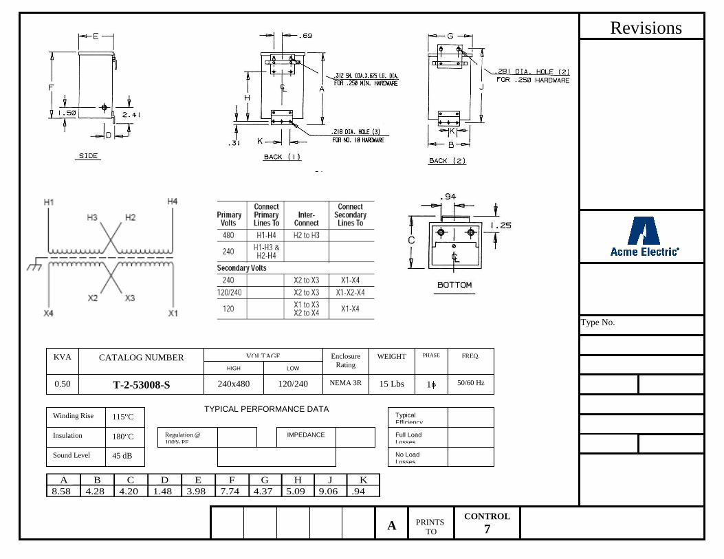
Revisions
Type No.
CONTROL
7 PRINTS
TO A
KVA
0.50
CATALOG NUMBER
T-2-53008-S
VOLTAGE
HIGH LOW
240x480 120/240
Enclosure
Rating
NEMA 3R
WEIGHT
15 Lbs
PHASE
1
FREQ.
50/60 Hz
TYPICAL PERFORMANCE DATA
Insulation
Sound Level
IMPEDANCE
Regulation @
100% PF
Winding Rise 115 C
180 C
45 dB
Typical Efficiency
Full Load Losses
No Load Losses
A B C D E F G H J K
8.58 4.28 4.20 1.48 3.98 7.74 4.37 5.09 9.06 .94