ejemplo amathcad buck boost
TRANSCRIPT

7/23/2019 Ejemplo aMathcad Buck Boost
http://slidepdf.com/reader/full/ejemplo-amathcad-buck-boost 1/5
6. Buck-boost Converter
Circuit and its parameters:
C
200uIC = 0
V-
V+
PARAMETERS:
Fs = 100kD = 0.6
0
I
p u l s e
outDiode
Dideal
V1
12Vdc
L
100uHIC = 0
R1
3
V2
TD = 0TF = 10nPW = {D/Fs}PER = {1/Fs}V1 = 0TR = 10nV2 = 15
Q1
MOSFET
Basic Formula:
D D
V V g
o
−= 1 RV I I o
Do == L D I D I )1( −= L s g DI I I ==
Pspice Simulation:
alculation:
vout
i L
C
Circuit Parameters:
Vg 12:= Vo 18:=L 100 10
6−⋅:= C 200 10
6−⋅:= f 100 10
3⋅:= R 3:=
Initial guess D 0.5:=
Given
Vo
Vg
D
1 D− D Find D( ):= D 0.6=
7/23/2019 Ejemplo aMathcad Buck Boost
http://slidepdf.com/reader/full/ejemplo-amathcad-buck-boost 2/5
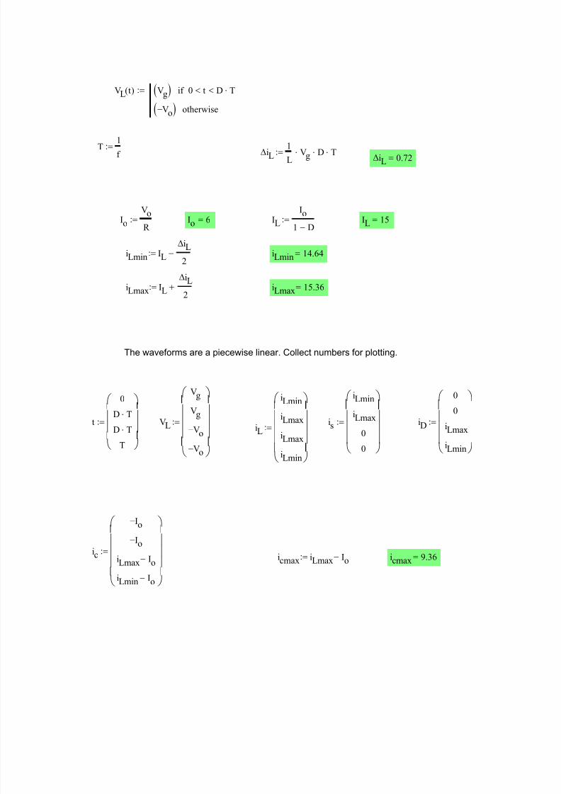
icmax 9.36=icmax iLmax Io−:=ic
Io−
Io−
iLmax Io−
iLmin Io−
:=
iL
iLmin
iLmax
iLmax
iLmin
:= iD
0
0
iLmax
iLmin
:=is
iLmin
iLmax
0
0
:=VL
Vg
Vg
Vo−
Vo−
:=t
0
D T⋅D T⋅
T
:=
The waveforms are a piecewise linear. Collect numbers for plotting.
iLmax 15.36=iLmax IL∆iL
2+:=
iLmin 14.64=iLmin IL
∆iL
2−:=
IL 15=IL
Io
1 D−:=Io 6=Io
Vo
R :=
∆iL 0.72=∆iL
1
LVg⋅ D⋅ T⋅:=
T 1
f :=
VL t( ) Vg( ) 0 t< D T⋅<if
Vo−( ) otherwise
:=

7/23/2019 Ejemplo aMathcad Buck Boost
http://slidepdf.com/reader/full/ejemplo-amathcad-buck-boost 3/5
0 5 .10 6
1 .10 5
20
13.33
6.67
6.67
13.33
20Inductor Voltage
VL
t
0 2.5 .10 6
5 .10 6
7.5 .10 6
1 .10 5
14.5
14.75
15
15.25
15.5Inductor Current
iL
t
0 5 .10 6
1 .10 5
5
10
15
20Switch current
is
t0 5 .10
61 .10
5
5
10
15
20Diode current
iD
t
Is D IL⋅:= Is 9= ID 1 D−( ) IL⋅:= ID 6=
0 5 .10 6
1 .10 5
10
6.67
3.33
3.33
6.6710
Capacitor current
ic
t
∆vo1
CIo⋅ D⋅ T⋅:= ∆vo 0.18=
Ig Is:= Ig 9= Vg 12= Io 6= Vo 18=
Pg Vg Ig⋅:= Pg 108= Po Vo Io⋅:= Po 108=
Due to ideal components (switch, diode, L and C) that we assume, the circuit is lossless, the
efficiency is 100% and as such Pg = Po.

7/23/2019 Ejemplo aMathcad Buck Boost
http://slidepdf.com/reader/full/ejemplo-amathcad-buck-boost 4/5
Lmin 2.4 10 6−
×=∆iL1
LVg⋅ D⋅ T⋅
Lmin1
∆iL
Vg⋅ D⋅ T⋅:=
iL2
iLmin
iLmax
iLmax
iLmin
:=∆iL 30=
iLmax 30=∆iL iLmax:=iLmax 30=iLmax 2 IL⋅:=iLmin 0:=
IL 15=IL
Io
1 D−:=Io 6=Io
Vo
R :=
R 3:=
Case II: R, f, and other circuit parameters are kept constant, L is varied
R 125=R Vo
Io
:=
iL1
iLmin
iLmax
iLmax
iLmin
:=Io 0.144=Io 1 D−( ) IL⋅:=IL 0.36=IL
∆iL2
:=
Case I: L, f, and other parameters are kept constant, R is varied iLmax ∆i:=iLmin 0:=
DCM/CCM Boundary
Case III: R, L, and other circuit parameters are kept constant, f is varied
R 3:=Io
Vo
R := Io 6= IL
Io
1 D−:= IL 15=
iLmin 0:= iLmax 2 IL⋅:= iLmax 30= ∆iL iLmax:= iLmax 30=
∆iL 30=
f min1
∆iL
Vg⋅ D⋅ 1
L⋅:=
∆iL1
LVg⋅ D⋅
1
f ⋅ f min 2.4 10
3×=

7/23/2019 Ejemplo aMathcad Buck Boost
http://slidepdf.com/reader/full/ejemplo-amathcad-buck-boost 5/5
Collect numbers for plotting
t1
0
D
f min
D
f min
1
f min
:= iL3
iLmin
iLmax
iLmax
iLmin
:= IL3
15
15
15
15
:= IL2 IL3:=IL1
0.36
0.36
0.36
0.36
:=
Tmax1
f min
:= Tmax 4.167 10 4−
×=
Waveforms for iL and IL:
0 5 .10 6
1 .10 5
0
0.25
0.5
0.75
1Case I
iL1
IL1
t
0 5 .10 6
1 .10 5
0
10
20
30
40Case II
iL2
IL2
t
0 2 .10 4
4 .10 4
6 .10 4
0
20
40Case III
iL3
IL3
t1
-tammat-