spatial channel model
TRANSCRIPT

8/2/2019 Spatial Channel Model
http://slidepdf.com/reader/full/spatial-channel-model 1/39

8/2/2019 Spatial Channel Model
http://slidepdf.com/reader/full/spatial-channel-model 2/39

8/2/2019 Spatial Channel Model
http://slidepdf.com/reader/full/spatial-channel-model 3/39
NOT for distribution, confidential
2
Channel Models for Multiple Antennas
The spatial properties of channels are extremelyimportant in determining the performance of multipleantenna systems
Diversity scheme may correspond to its own channel model
Need to consider Time delay spread
Angular spread
Adaptive array antenna geometries
Angular spread depends on
Local scattering environment Antenna heights
Time variability of spatial channel is the function of UEspeed. (movement)

8/2/2019 Spatial Channel Model
http://slidepdf.com/reader/full/spatial-channel-model 4/39
NOT for distribution, confidential
3
Properties of Spatial Correlation
Lower correlation with Larger angular spread
Larger element spacing
To get low correlation UE: 0.2 wavelength due to the larger angular spread BS: 40 wavelength due to the small angular spread
Assumptions: Long-term properties of the channel remain
unchanged over time (time-invariant) It is a slow varying effect similar to shadow fading
Independence between different taps

8/2/2019 Spatial Channel Model
http://slidepdf.com/reader/full/spatial-channel-model 5/39
NOT for distribution, confidential
4
SCM Generation Method
Spatially correlated multiple channels can begenerated by the linear transformation of thesame number of uncorrelated channels
(t)gT(t)h
HTTR Correlation matrix:
(t)g
(t)g
(t)g
(t)g
L
2
1
Uncorrelated channels:

8/2/2019 Spatial Channel Model
http://slidepdf.com/reader/full/spatial-channel-model 6/39
NOT for distribution, confidential
5
Block Diagram for SCM Generation
Multiple
channelgeneration
Linear
transformationwith T
)(1 t g)(1 t h
)(t g L
)(2 t g
)(t h L
)(2
t h
Matrix squareroot
computation
T
H T T R
Spatial correlationcoefficients
(t)gt(t)hL
1 j
jiji

8/2/2019 Spatial Channel Model
http://slidepdf.com/reader/full/spatial-channel-model 7/39
NOT for distribution, confidential
6
Alternative Implementationfor Rx Diversity Simulations
When spatial covariance matrices are equal foreach tap
Equivalent simulation method without changethe channel impulse responses by transformationof
Received signal before AWGN
Antenna weightwTv and
r
r
r
T
s
s
s
L
2
1
L
2
1

8/2/2019 Spatial Channel Model
http://slidepdf.com/reader/full/spatial-channel-model 8/39
NOT for distribution, confidential
7
Examples of Spatial Correlation Matrix
Spatial correlation matrix for 4 antenna case
Spatially uncorrelated channels: a=b=c=0 Recommended correlation coefficients
[TSGR1#17(00)1358]
1*a*b*c
a1*a*b
ba1*a
cba1
R

8/2/2019 Spatial Channel Model
http://slidepdf.com/reader/full/spatial-channel-model 9/39
NOT for distribution, confidential
8
Recommended Correlation Parameters[TSGR1#17(00)1358]
Environment ParametersRecommended path
model Angular spread
Macro cell
(Rural area)
a=0.97 exp(-0.8 j)
b=0.94 exp(-1.6 j)c=0.88 exp(-2.4 j)
1-path Rayleigh
Vehicular A
10° AS
15° AoA
Micro cell
(Urban area)
a=0.7 exp(-2.2 j)
b=0.1 exp(-1.2 j)
c=0.2 exp(-3.0 j)
Pedestrian A 45° AS
60° AoA
Pico cell oruncorrelated
a, b, c = 0 Pedestrian A Large angular
spread
8/2/2019 Spatial Channel Model
http://slidepdf.com/reader/full/spatial-channel-model 10/39
NOT for distribution, confidential
9
What Next?
Rx or Tx Diversity schemes have been simulated withthose correlation matrices.
Is it Reliable? Reasonable? Enough?
Need verification of the recommended SCM
Need some basics of array signal processing
Rx signal model to array antenna
Steering vector Power Spectrum Density (PSD)
Eigenbeam pattern

8/2/2019 Spatial Channel Model
http://slidepdf.com/reader/full/spatial-channel-model 11/39
NOT for distribution, confidential
10
Received Signal Model
(t)nθas(t)
(t)nαs(t)
(t)nαs(t)
(t)nαs(t)
(t)ns(t)
(t)r
L1-L
32
21
1
Steering vector is the function of AOA dependent on the antenna geometry
A o
An
0
Node B
s(t)
Rx signal with coherent assumption
1-L
1
α
α
1
θa
8/2/2019 Spatial Channel Model
http://slidepdf.com/reader/full/spatial-channel-model 12/39
NOT for distribution, confidential
11
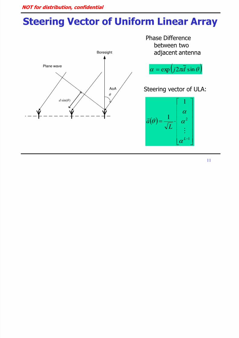
Steering Vector of Uniform Linear Array
1
2
1
1
L
L
a
sin~
2exp d j
Phase Differencebetween twoadjacent antenna
Steering vector of ULA:
Plane wave
)sin( d
Boresight
AoA

8/2/2019 Spatial Channel Model
http://slidepdf.com/reader/full/spatial-channel-model 13/39
NOT for distribution, confidential
12
Discrete Uniform Distribution Model
A o
A
n
0
Node B
UE
(t)nθa1Q
1s(t)(t)r
Q
0q
q
Angle of sub-paths:
HQ
0q
qq θaθa1)(Q
1R
σ2
1
Q
qθθq
Correlation Matrix:
Rx Signal:

8/2/2019 Spatial Channel Model
http://slidepdf.com/reader/full/spatial-channel-model 14/39
NOT for distribution, confidential
13
More Basic Definitions
θaRθaθPH
1
Power Spectrum Density
θawwθa
wθaθP
HH
2H
2
Beam pattern of antenna weight
H
LLL
H
222
H
111 wwλ wwλ wwλ R
Eigenvalue decomposition

8/2/2019 Spatial Channel Model
http://slidepdf.com/reader/full/spatial-channel-model 15/39
NOT for distribution, confidential
14
-80 -60 -40 -20 0 20 40 60 80-20
-10
0
10Angular PSD of correlation matrix
Angle (degree)
G a i n ( d B )
-80 -60 -40 -20 0 20 40 60 80-30
-20
-10
0Dominant Eigenbeam Pattern
Angle (degree)
G a i n ( d B )
PSD of Macro Cell Model: 70 AoA, 10 AS
Long-term average power
profile according toangle
Beam pattern of thedominant eigenvector
Dominant eigenvector isassociated with 99.9%power
AoA is around 15°
AS = 10°

8/2/2019 Spatial Channel Model
http://slidepdf.com/reader/full/spatial-channel-model 16/39
NOT for distribution, confidential
15
-50 0 50-40
-30
-20
-10
0
Angle (degree)
G a i n ( d B )
Dominent Eigenbeam Pattern
-50 0 50-40
-30
-20
-10
0
Angle (degree)
G a i n ( d B )
2nd Eigenbeam Pattern
-50 0 50-40
-30
-20
-10
0
Angle (degree)
G a i n
( d B )
3rd Eigenbeam Pattern
-50 0 50-40
-30
-20
-10
0
Angle (degree)
G a i n
( d B )
4th Eigenbeam Pattern
Eigenbeam Patterns of Macro Model
0 %0 %
99.9% 0.1%
8/2/2019 Spatial Channel Model
http://slidepdf.com/reader/full/spatial-channel-model 17/39
NOT for distribution, confidential
16
-80 -60 -40 -20 0 20 40 60 80-30
-20
-10
0
10Angular PSD of correlation matrix
Angle (degree)
G a i n ( d B )
-80 -60 -40 -20 0 20 40 60 80-40
-30
-20
-10
0Angular PSD of dominant eigenvector
Angle (degree)
G a i n ( d
B )
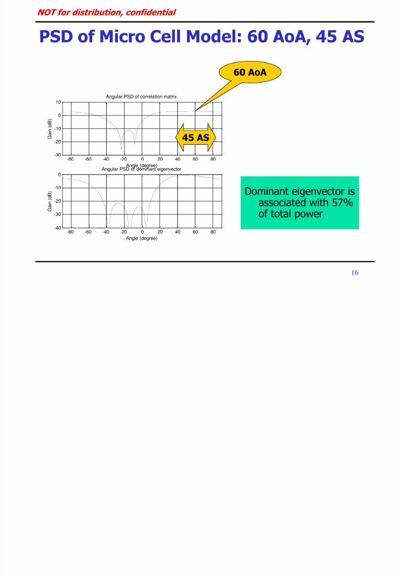
PSD of Micro Cell Model: 60 AoA, 45 AS
Dominant eigenvector isassociated with 57%of total power
60 AoA
45 AS

8/2/2019 Spatial Channel Model
http://slidepdf.com/reader/full/spatial-channel-model 18/39
NOT for distribution, confidential
17
-50 0 50-40
-30
-20
-10
0
Angle (degree)
G a i n ( d B )
Dominent Eigenbeam Pattern
-50 0 50-40
-30
-20
-10
0
Angle (degree)
G a i n ( d B )
2nd Eigenbeam Pattern
-50 0 50-40
-30
-20
-10
0
Angle (degree)
G a i n ( d
B )
3rd Eigenbeam Pattern
-50 0 50-40
-30
-20
-10
0
Angle (degree)
G a i n ( d
B )
4th Eigenbeam Pattern
Eigenbeam Patterns of Micro Cell
0.4 %3.7 %
57.2% 38.7%

8/2/2019 Spatial Channel Model
http://slidepdf.com/reader/full/spatial-channel-model 19/39
NOT for distribution, confidential
18
Need Common Correlation Model
Very limited simulation environments can beconsidered
Eigenbeamformer scheme has adopted this spatialchannel model
Uniformly distributed power on an angular region
Common & more reliable simulation spatial
channel model is required Need specific descriptions of more channel
parameters, AOA, PAS, AS, etc

8/2/2019 Spatial Channel Model
http://slidepdf.com/reader/full/spatial-channel-model 20/39
NOT for distribution, confidential
19
Spatial Channel Model by AHG
Text description: SCM-077 11/2002 Recommended to use MIMO physical layer channel
model proposed
SCM AHG (AH-62) from 3GPP & 3GPP2
Develop and specify parameters and methodsassociated with Link level spatial channel model
For calibration only
System level spatial channel model Define physical parameters and system evaluation
methodology

8/2/2019 Spatial Channel Model
http://slidepdf.com/reader/full/spatial-channel-model 21/39
NOT for distribution, confidential
20
Link level channel model
Developed and specified by 3GPP-3GPP2 SCM AH
Only for calibration purposes
Reflect only one snapshot of the channel behavior
Do not account for system attributes such asscheduling and HARQ
Only for comparison of performance results fromdifferent implementation of a given algorithm
Status: 95% completed
Distribution is not defined yet
8/2/2019 Spatial Channel Model
http://slidepdf.com/reader/full/spatial-channel-model 22/39
NOT for distribution, confidential
21
System level channel model
Required for the final algorithm comparison Define the methodology for generating the
spatial channel coefficients between BS and MS
95% completed Will not be covered here but later

8/2/2019 Spatial Channel Model
http://slidepdf.com/reader/full/spatial-channel-model 23/39
NOT for distribution, confidential
22
Terminologies MS = UE = terminal
= subscriber unit
BS = Node-B = BTS
AS = angle spread
= azimuth spread
Path = Ray Path component
= Sub-ray
PAS = power azimuthspectrum
DoT = direction of travel
AoA = angle of arrival
AoD = angle of departure
PDP = power delay profile
A o
A
n
0 BS
UE
D o T

8/2/2019 Spatial Channel Model
http://slidepdf.com/reader/full/spatial-channel-model 24/39
NOT for distribution, confidential
23
Parameters of Link Level SCM
Model Case I Case II Case III Case IV
3GPP Case B Case C Case D Case A
3GPP2 Model A, D, E Model C Model B Model F
PDP Mod. Pedestrian A Vehicular A Pedestrian B Single path
Speed (Km/h)1) 3
2) 30, 1203, 30, 120 3, 30, 120 3
# of paths1) 4 + 1 (LOS on, K=6 dB)
2) 4 (LOS off)6 6 1
Relative pathpower (dB)
& Delay (ns)
LOS on
0.0
-6.51
-16.21
-25.71
-29.31
LOS off
–Inf
0.0
-9.7
-19.2
-22.8
0
0
110
190
410
0.0
-1.0
-9.0
-10.0
-15.0
-20.0
0
310
710
1090
1730
2510
0.0
-0.9
-4.9
-8.0
-7.8
-23.9
0
200
800
1200
2300
3700
0 0
Multipath fading propagation conditions

8/2/2019 Spatial Channel Model
http://slidepdf.com/reader/full/spatial-channel-model 25/39
NOT for distribution, confidential
24
Parameters of Link Level SCM…
Model Case I Case II Case III Case IV
Topology Reference: ULA with 0.5, 4, 10 spacing N/A
PASLaplacian distribution with
RMS angle spread of 2 or 5 degrees per path
depending on AoA/AoD
N/A
AoD/AoA
(degrees)
50 for 2 RMS AS per path
20 for 5 RMS AS per pathN/A
Antenna gainpattern
3 or 6 sector antenna pattern
(For diversity oriented applications rather than beamforming applications)
Spatial parameters for NodeB

8/2/2019 Spatial Channel Model
http://slidepdf.com/reader/full/spatial-channel-model 26/39
NOT for distribution, confidential
25
Parameters of Link Level SCM…
Model Case I Case II Case III Case IV
Topology Reference 0.5 N/A
PAS
1) LOS on: Fixed AoA forLOS component, remainingpower has 360 degree
uniform PAS. ( RMS anglespread of 104 degrees)
2) LOS off: Laplaciandistribution with RMS anglespread of 35 degrees perpath
Laplacian distributionwith RMS anglespread of 35 degreesper path
OR
360 degree uniformPAS ( RMS anglespread of 104degrees)
Laplacian distributionwith RMS anglespread of 35 degreesper path
N/A
DoT
(degrees) 0 22.5 -22.5 N/A
AoA
(degrees)
22.5 (LOS component)
67.5 (all other paths)67.5 (all paths)
22.5 (odd paths)
-67.5 (even paths)N/A
Antenna gainpattern
Omni directional with -1 dBi gain
Spatial parameters for UE

8/2/2019 Spatial Channel Model
http://slidepdf.com/reader/full/spatial-channel-model 27/39
NOT for distribution, confidential
26
Assumptions of Link Level SCM
Spatial channel parameters per path Each resolvable path is characterized by spatial
channel parameters: AS, AoA, PAS
All paths are assumed independent
Array Topologies
Allow any type of antenna configuration, but must be
shared to reproduce and verify the results ULA with element spacing of 0.5, 4, 10 wavelengths

8/2/2019 Spatial Channel Model
http://slidepdf.com/reader/full/spatial-channel-model 28/39
NOT for distribution, confidential
27
Antenna Gain Patterns
UE: -1 dBi gain omni-direction Node B uplink/downlink
Only for diversity oriented implementations (large spacing)
Need different antenna patterns for beamforming applications
3 sector cell Bandwidth 70°, Maximum attenuation 20 dB, 14 dBi gain
6 sector cell
Bandwidth 35°, Maximum attenuation 23 dB, 17 dBi gain
Sector antenna formula in dB scale
180θ180,A,θ
θ12-minθA m
3dB
O f di ib i fid i l

8/2/2019 Spatial Channel Model
http://slidepdf.com/reader/full/spatial-channel-model 29/39
NOT for distribution, confidential
28
Sector Antenna Patterns at NodeB
-120 -100 -80 -60 -40 -20 0 20 40 60 80 100 120-25
-20
-15
-10
-5
0Antenna Pattern for 3 sector cell
Azimuth in Degrees
G a i n i n d B
BW = 70 degreeBW = 70 degree
maximum attenuation (Am)
3 sector antenna pattern
NOT f di t ib ti fid ti l

8/2/2019 Spatial Channel Model
http://slidepdf.com/reader/full/spatial-channel-model 30/39
NOT for distribution, confidential
29
Sector Antenna Patterns at NodeB…
-120 -100 -80 -60 -40 -20 0 20 40 60 80 100 120-25
-20
-15
-10
-5
0Antenna Pattern for 6 sector cell
Azimuth in Degrees
G a i n i n d B
BW = 35 degreeBW = 35 degree
maximum attenuation (Am)
6 sector antenna pattern
NOT f di t ib ti fid ti l

8/2/2019 Spatial Channel Model
http://slidepdf.com/reader/full/spatial-channel-model 31/39
NOT for distribution, confidential
30
Average Received Power
θGσ
θθ2expNθP 0
dθθPNπ
π
1
0
/10θA10θG
Laplacian distributed PAS
Normalization factor
Gain pattern in linear scale
θ Angle of Arrival
θEθEσ22 RMS angle spread
NOT f di t ib ti fid ti l

8/2/2019 Spatial Channel Model
http://slidepdf.com/reader/full/spatial-channel-model 32/39
NOT for distribution, confidential
31
Average Received Power at NodeB
-50 -40 -30 -20 -10 0 10 20 30 40 500
0.02
0.04
0.06
0.08
0.1
0.12
0.14
0.16
0.18
0.2Avaerage received power
Angle (degree)
P A S
v a l u e P ( )
3 sectored antenna with AoA = 20 and RMS AS = 5
NOT f di t ib ti fid ti l

8/2/2019 Spatial Channel Model
http://slidepdf.com/reader/full/spatial-channel-model 33/39
NOT for distribution, confidential
32
Average Received Power at UE
Laplacian distributed PAS with omni-directional gain 1θG
σ
θθ2expNθP 0
NOT for distribution confidential

8/2/2019 Spatial Channel Model
http://slidepdf.com/reader/full/spatial-channel-model 34/39
NOT for distribution, confidential
33
Average Received Power at UE…
22.5 AoA & 35 RMS AS
-150 -100 -50 0 50 100 1500
0.002
0.004
0.006
0.008
0.01
0.012
0.014
0.016
0.018
0.02Avaerage received power
Angle (degree)
P A S
v a l u e P ( )
NOT for distribution confidential

8/2/2019 Spatial Channel Model
http://slidepdf.com/reader/full/spatial-channel-model 35/39
NOT for distribution, confidential
34
Average Received Power at UE…
22.5 AoA & 104 RMS AS (uniform over 360 degree PAS)
-150 -100 -50 0 50 100 1500
1
2
3
4
5
6
7
8x 10
-3 Avaerage received power
Angle (degree)
P A S
v a l u e P ( )
NOT for distribution confidential

8/2/2019 Spatial Channel Model
http://slidepdf.com/reader/full/spatial-channel-model 36/39
NOT for distribution, confidential
35
Doppler Spectrum at UE
Dependent on DoT
PAS
AoA
A o
A
n
0 BS
UE
D o T
NOT for distribution confidential

8/2/2019 Spatial Channel Model
http://slidepdf.com/reader/full/spatial-channel-model 37/39
NOT for distribution, confidential
36
Generation of link level channel model
Average received power Angle theta represents path components
Its distribution is TBD Uniformly distribution over [-180 180] degrees
Channel implementation techniques Correlation based
Ray based
Details are TBD Reference correlation values are provided
Nokia to provide formulas for computing correlationmatrices
NOT for distribution confidential

8/2/2019 Spatial Channel Model
http://slidepdf.com/reader/full/spatial-channel-model 38/39
NOT for distribution, confidential
37
Future Plan
Link-level SCM generation and verification MatLab, SPW, etc
Continual study of system-level models
Using these models for performance testing invarious development projects (TDD, FDD, EV-DV,
TD-SCDMA)
NOT for distribution confidential

8/2/2019 Spatial Channel Model
http://slidepdf.com/reader/full/spatial-channel-model 39/39
NOT for distribution, confidential
References
Old 3GPP Model: TSGR1#14(00)0867
TSGR1#15(00)1067
TSGR1#16(00)1187
TSGR1#17(00)1358 Tx Div Model:
TSGR1#26(02)
0765, 770
TSGR1#29(02)1139,1419,1440
1441 (TR25.869)
MIMO Model: TSGR1#22(01)1132
TSGR1#22(01)1136
TSGR1#23(01)1179 TSGR1(02)0141
SCM-077,November 2002
by 3GPP-3GPP2