south dakota science and technology authority …
TRANSCRIPT

SOUTH DAKOTA SCIENCE AND TECHNOLOGY AUTHORITY
REQUEST FOR PROPOSALS (RFP)
ORE HONDO FAN BACKUP
RFP #2021-13
Mandatory Site Visit: May 25, 2021 10:00 A.M. – 12:00 P.M.
Pre-Registration for Site Visit May 21, 2021 (by close of business)
Questions Submitted: June 1, 2021 (by close of business)
Questions & Answers Posted: June 4, 2021 (by close of business)
Proposal Due Date: June 21, 2021 (by 2:00 P.M)
South Dakota Science and Technology Authority is seeking a industrial engineering/contractor offeror to provide a turn-key design/build solution for the design, fabrication, and installation of a new backup underground ventilation fan, located on the surface near Kirk road, and electrical infrastructure upgrades required to support the new and existing fans. The completion of this project will provide ventilation redundancy to an existing fan used for ventilating the underground facilities at the Sanford Underground Research Facility located in Lead, South Dakota. The best value selection process will be used for awarding this contract. Selection will be made based on tradeoffs among price and non-price evaluation factors. These non-price evaluation factors have been detailed in Section 7. Fixed bid prices shall be submitted for all items indicated herein.
The OHFC provides the main ventilation for the underground spaces at SURF. In the event this fan cannot operate, the underground will naturally ventilate at significantly lower flows and with less predictability than powered ventilation. These natural flows, while sufficient to provide breathable air to support personnel, will not provide enough airflow to support normal underground operations and must be limited. To reduce the impact to underground operations, offerors must limit powered ventilation outages as much as possible. More detail is provided in the following sections.
Documents included in this Request for Proposal include:
A. This Request for ProposalB. Draft ContractsC. Contractor’s Pre-Qualification ESH QuestionnaireD. Exhibits:
1. American Davidson Layout Drawings (HMC Drawings.pdf) – This PDF contains
1

all the construction drawings for the American Davidson fan. 2. American Davidson Fan & Motor Information (AD Fan & Motor Info.pdf) – This
PDF provides information on the American Davidson fan and motor. 3. Fan and Substation One Line Diagrams (One-Line Oro Hondo Sub to Fan Site.pdf)
– This PDF contains the One-line diagrams for the OHFC and substation. 4. Oro Hondo Transformers (Oro Hondo Transformers.pdf) – This PDF provides
information on the transformers in the Oro Hondo substation. 5. American Davidson E-House (American Davidson E-House info.pdf) – This PDF
provides all the information and drawings on the newly installed American Davidson E-house.
6. Spendrup Fan (Spendrup Fan Info.pdf) – This PDF provides information on the Spendrup fan.
7. Oro Hondo Fan Site Scan (Oro Hondo 1.rcp) – This Recap file contains the laser scan of the OHFC and access road.
8. East Bridge Scan (Kirk Bridge East 1.rcp) – This Recap file contains the laser scan of the East Kirk bridge.
9. West Bridge Scan (Kirk Bridge West 1.rcp) – This Recap file contains the laser scan of the West Kirk Bridge.
10. Arc Flash Label Requirements & Industrial Controls design Standard (SURF Arc Flash Label Requirements Rev2.pdf & SURF Final Draft Design Standard for Industrial Controls_Final.pdf) – These pdfs contains the arc flash label requirements and industrial controls design standard for the SURF property.
11. Example Transformers and Switchgear (Transformers & Switchgear Examples.pdf) – This pdf contains examples of transformers and switchgear that have been recently purchased and installed at SURF.
12. SDSTA’s Division 1 Specifications (SDSTA Division 1 Guide Spec Jan 2020 Oro Hondo Backup.pdf) – This pdf contains the Division 1 specifications that contractors must follow when working on SDSTA projects.
Definitions for terms and acronyms used in this Request for Proposal:
DOE – Department of Energy DUNE – Deep Underground Neutrino Experiment E-House – Self-contained electrical enclosure/building HMC – Homestake Mining Company LBNF – Long Baseline Neutrino Facility MVS – Mine Ventilation Services, Inc. OHFC – Oro Hondo Fan Complex
2

Offeror – Engineering/Construction firm interested in this project RFP – Request for Proposal SDSTA – South Dakota Science and Technology Authority SURF – Sanford Underground Research Facility VFD – Variable Frequency Drive WC – Water Column, water gauge, inches H2O
1.0 Scope
This is a design-build project for the purchase and installation of a new backup underground ventilation fan and electrical infrastructure upgrades required to support the new and existing fans at the OHFC. Because these upgrades are all tied so closely together, SDSTA is requesting that the entire project be completed turn-key by a offeror capable of performing, through in-house resources or by coordinating subcontractors, the design, fabrication, on-site construction/installation, and commissioning of this backup fan system and supporting infrastructure. The selected offeror must follow the guidelines and requirements listed in this RFP and the attached documents. The offeror’s submitted package must include all items required to complete this project (design, procurement, & installation).
The scope of work interested offeror’s will be responsible for consists of the following five parts:
1. Evaluating existing conditions (section 3.0) a. Current Oro Hondo fan site and configuration b. Electrical distribution to the site
2. Oro Hondo Fan Site Design Requirements (Section 4.0) 3. Backup fan selection (section 5.1)
a. Select a proposed backup fan 4. Electrical distribution changes (section 5.2) 5. Procurement, installation, and commissioning of all items associated with this project
(section 5.0)
SDSTA requests that Offeror’s submit proposals as outlined in section 7.0 so that a fair and equal comparison of proposals received can be completed.
All submitted proposals should be supplemented by attachments providing detailed descriptions, diagrams, explanations, and pertinent information relating to the proposed equipment, and services.
3

2.0 Background Information
The main SURF ventilation network relies on a large primary exhaust fan, located at the OHFC, to pull fresh air from the surface down the Ross and Yates Shafts. The fresh air flows across the various levels of the underground footprint to the Oro Hondo Shaft where the air continues back to the surface and is exhausted to the atmosphere. A much smaller secondary fan that is currently installed at the OHFC acts as a limited capacity backup to the primary fan using the same airflow path. An aerial photo of the OHFC is shown in Figure 2.0. See Exhibit 7 for a complete laser scan of this property and Exhibit 1 for the original construction drawings.
2.1 Primary ventilation for the underground facilities at SURF is provided by an American Davidson direct driven, centrifugal fan powered by a GE 3000 HP synchronous motor. The original 3000 HP rated GE LCI VFD was replaced in 2020 with a 2000 HP PWM Allen-Bradley Powerflex 7000 medium voltage VFD.
2.2 Secondary ventilation is provided by a 350 HP vane-axial fan manufactured by Spendrup. The 350 HP secondary fan will not supply the required amount of air to support the normal SURF operations and construction and operational phases of the LBNF construction project or the DUNE experiment.
Figure 2.0 - Oro Hondo Fan Complex in Kirk Canyon
SURF must provide a redundant ventilation system for existing and future underground science facilities. The limited ventilation capability provided by the backup 350 HP Spendrup fan necessitates the replacement with a newer and larger fan.
4

3.0 Existing Conditions
3.1 Power Distribution
OHFC site power is supplied on overhead lines from the nearby Oro Hondo Substation, which is owned and operated by SDSTA. The substation is supplied at 69kV by Black Hills Energy.
Two transformers located at the substation are dedicated to the OHFC and step 69kV down to 2400 volts. The 2400-Volt distribution system is an ungrounded delta-delta system. A manually operated source-transfer switch on the secondary side of the transformers, located at the substation, selects which transformer is in-use. The transformers cannot be operated in parallel.
The length of the 2400-Volt overhead line from the metal clad switchgear at the Oro Hondo Substation to the OHFC is approximately 400 feet (to be verified by the contractor).
A complete power distribution diagram of the Oro Hondo 2400-Volt system and OHFC is shown in Exhibit 3. Exhibit 4 contains photographs of transformer nameplates.
Transformer Data:
Main transformer – GE, Delta-Delta, Rated 3,000 kVA continuous @ 55 °C Rise, self-cooled, oil. 67kV primary (+/- 5%), 2400-Volt secondary, Impedance = 9.01%, K-factor = 4 BIL: HV = 350kV, LV = 110kV. Backup transformer – Westinghouse, Delta-Delta, Rated 2,500 kVA continuous @ 55 °C Rise, self-cooled, oil. 67kV primary (+/- 5%), 2300-Volt secondary. Impedance = 7.4% Available short-circuit kVA = 32,000. BIL: HV = 350kV, LV = 60kV.
Note: The Westinghouse back-up transformer was upgraded to 125% of original self-cooled nameplate rating.
3.2 Primary and Secondary Fan Motors
3.2.1 Primary American Davidson
5

The American Davidson motor is the original GE 3000 horsepower synchronous motor with brushless exciter that was installed in 1986. The motor is housed in a weather-proof building and has been maintained regularly since it was originally installed. It was disassembled, cleaned, and tested in 2009.
Exhibit 2 provides pages from the original GE HMC project document “GEK-95638 Adjustable Speed Drives Systems “that contain information and specifications for the existing motor, and exciter along with photographs of motor and exciter nameplates.
3.2.2 Secondary Spendrup
The Spendrup motor is a 350-horsepower induction motor. The motor is housed inside the vane-axial fans ducting. Photographs of the motor’s nameplate can be found in Exhibit 6.
3.3 Primary and Secondary Fan Control Buildings
3.3.1 Primary American Davidson
The American Davidson VFD is housed in an insulated modular motor control E-house. The E-House contains the VFD, and all lighting, heating, cooling and support equipment required to operate the VFD. Exhibit 5 provides detailed information on the E-house and equipment inside. VFD ratings for the American Davidson fan are provided in Appendix A.
3.3.2 Secondary Spendrup
The Spendrup VFD is housed in an uninsulated legacy metal building containing other leftover drives and motors from HMC that no longer function. The building contains the Spendrup’s VFD, building lighting, heating, and hoist controls for the fan duct block off gates. Figure 4.1 provides a breakdown of the electrical equipment inside this building.
3.4 Primary and Secondary Fans
3.4.1 Primary American Davidson
The SURF ventilation system operates continuously 24 hours/day, 365 days/year. The primary Oro Hondo fan is an American Davidson type 1400-SIBAB92, single inlet, backward inclined airfoil blade impeller, centrifugal fan direct coupled to a 3000 HP, 720 RPM synchronous motor controlled by a 2000 HP PWM Allen-Bradley Powerflex 7000 medium voltage VFD.
3.4.2 Secondary Spendrup
The secondary Spendrup fan will only run in the event the primary fan needs maintenance or experiences an unexpected outage. In the current configuration, the Spendrup produces 144 KFCM @ 4.1 in. w.g. through the same ventilation pathways as the American Davidson.
6

3.5 PLC Control System
A General Electric 90/30 PLC cabinet is currently installed inside the American Davidson Fan E-House to monitor instruments and fans at the OHFC.
3.6 Communication Network
SDSTA’s IT Department manages, maintains, and secures the network infrastructure, servers, and SURF issued computing devices. The physical network infrastructure consists of a fiber-optic backbone plant that extends through-out the surface and underground facilities. The network architecture integrates separate logical networks into a facility-wide office automation network. Each logical network is isolated from the others through firewall zones. The telephone system consists of both wired digital and VoIP telephones.
Telephone service, office automation and control system networks are available at the OHFC site over fiber-optic cables.
3.7 Site Access Restrictions
Access to the OHFC is provided by Kirk Road that runs along the City of Lead boundary. Equipment and materials can access the OHFC from the East or West entrances. Kirk Road is wide enough to handle any widths that can travel normal highways. However, there are two pipe bridges that cross the road that can limit the maximum height of shipped loads depending on the chosen East or West route. The East and West pipe bridges are shown in Figure 3.0.
Exhibit 8 and 9 contain the recent laser scans of both bridges. The offeror will be responsible to review these scans and ensure all loads and equipment delivered to the OHFC are within the height restrictions of these bridges.
7

Figure 3.0 – OHFC Pipe Bridge Height Restrictions
Additionally, all loads that are shipped to the OHFC must travel on the short single lane OHFC access road that connects the OHFC to Kirk Road shown in Figure 3.0. Kirk Road is maintained by the City but the offeror will be responsible for maintaining the OHFC access road during this project to allow for equipment to be delivered and work to take place at the OHFC. Road maintenance may include snow removal, grading, or clearing to allow equipment to arrive at the OHFC. Access to the back of the OHFC is provided by a very narrow road between the OHFC perimeter fence and tree covered embankment shown in Figure 3.1. The offeror will be responsible for maintaining this path, if needed, and any work required to allow equipment or loads to travel on this path. Modifications/work may include clearing, fence removal, or grading depending on the level of access needed.
8

Figure 3.1 – OHFC Access Roads
4.0 Oro Hondo Fan Site Design Requirements
Provide a complete and integrated design for the purchase and installation of a new backup underground ventilation fan and electrical infrastructure upgrades required to support the new and existing fans at the Oro Hondo fan site and all other aspects described in this scope of work.
4.1 All scope items shall be developed, designed, and presented as a single, all inclusive, integrated design package.
4.2 Design reviews are required at 30, 60, and 90% completion. A review meeting shall be held at each of these design milestones. Draft design documents shall be submitted at least 7 days prior to each review meeting. Review meeting attendance shall include SDSTA, the successful offeror and their key subcontractors. The SDSTA will have a total of 14 calendar days to provide comments. The 30% and 90% design reviews shall have key offeror leaders present at the SURF with support personnel allowed to videoconference. The 60% may be done entirely by video conferencing.
9

4.3 The 30% design documents shall include at a minimum:
4.3.1 A Basis of Design (BOD) report including: 4.3.1.1 A separate section for each major component of the work scope
providing assumptions, calculations, and design data from which the design is based.
4.3.1.2 A section describing the approach to integrating all scope of work components into a single final design package.
4.3.2 A drawing set including general arrangement, mechanical, electrical, plumbing, controls, and civil/structural drawings including all project/equipment specifications for each division of work on the project.
4.4 The 60%, 90%, and 100% design documents shall include at a minimum:
4.4.1 A memorandum describing key changes from the previous deliverable.
4.4.2 Updated design report including responses to all comments provided in the previous deliverable.
4.4.3 Draft commissioning plan, with final plan delivered with the 100% deliverable.
4.4.4 A drawing set including general arrangement, mechanical, electrical, plumbing, controls, and civil/structural drawings including all project/equipment specifications for each division of work on the project.
4.4.5 Estimate for design support services for construction for RFI’s, differing site conditions, submittal reviews etc. This estimate should include projected hours and rates by discipline.
4.5 All requests for information (RFI) shall be formally documented in Submittal Exchange and managed by the Offeror. See Exhibit 12 for details.
4.6 Calculations and final drawings shall be approved, certified, and stamped by a Professional Engineer registered in the state of South Dakota.
4.7 All dimensions shall be in US Customary System (USCS) units unless specified otherwise.
4.8 All instructions, labels, name plates, placards, warning signs, drawings, documents, and other submittals shall be in English.
4.9 Requirements to be used during design are as follows:
4.9.1 The SURF site follows the Occupational Health and Safety Administration (OSHA) codes and standards. The codes and standards listed below shall also be followed where applicable. For items that OSHA and/or the IBC do not address, MSHA rules are referenced. If conflicts exist between code requirements, or in situations where no defined codes exist, consultation
10

with SDSTA, who shall be the deciding authority concerning design standards and/or code variances. Codes and standards include but are not limited to the following:
• ASHRAE (American Society of Heating, Refrigerating and Air- Conditioning Engineers)
• ASME (American Society of Mechanical Engineers)
• ASTM (American Society for Testing and Materials)
• AWS (American Welding Society)
• City of Lead Authority Having Jurisdiction
• Code of Federal Regulations (CFR), Mine Health and Safety Administration (MSHA), 30_CFR_56.12 (Surface Electricity)
• International Building Code (IBC)
• National Electric Code (NEC)
• National Fire Protection Association (NFPA)
• OSHA (Occupational Safety and Health Administration)
• ACI (American Concrete Institute)
• AISC (American Institute of Steel Construction)
5.0 Fabrication, Procurement, and Installation
The scope of work associated with this project requires interested offerors to provide turn-key solutions for the following features of work and all ancillary items associated with them:
• Specification development for all installed equipment and structures • New backup fan design, & procurement • Fan site preparation, excavation, installation, and commissioning • Electrical distribution reconfiguration.
Offerors submitting proposals should view the following requirements as guidance that should be addressed in design development. Various proposed solutions will be considered as long as the following requirements are met. Note that some additional information is provided for the contractor to consider as part of the RFP response.
11

5.1 Backup Fan Design and Procurement
This portion of work will require the offeror to evaluate the existing configuration (as described above) of the OHFC to design and purchase a new backup fan. This will require the following items:
• Evaluation of the existing site configuration and limitations to determine the optimum placement and connection of the new backup fan.
• Selection of a new backup fan that meets the attached fan specification, see Appendix B. A list of potential fan vendors is provided for offerors information. Using one of these vendors is not a requirement.
• Design of the fan and ducting to function with the Oro Hondo exhaust shaft that is shared with the existing American Davidson fan.
• Procurement of the fan and necessary ducting
5.1.1 Fan Specification
The SDSTA has contracted with Ventilation Innovation (VI) to develop a backup fan specification that will meet SURFs needs based on VentSim modeling of the underground ventilation flow path. VI has created a detailed fan specification that all supplied backup fans must meet at a minimum. The backup fan specification is attached to Appendix B. Additionally, all industrial controls supplied with this fan must follow SDSTA industrial controls design standard provided in Exhibit 10.
5.2 Fan Installation
Offerors will be responsible for the installation of the procured fan and ducting. Fan installation shall include the following items:
• Evaluation of the existing site conditions and infrastructure • Site modifications needed for the backup and existing American Davidson fans to
operate. Including but not limited to: o Demolition of existing ductwork, structures, or concrete that conflict with
the new fans design o Demolition of the red, blue, and purple areas outlined in Figure 5.0 o Any excavation and site preparation needed to support the new fan, ducting,
or ancillary equipment that is part of the fan package. This may include foundations, equipment pads, or buildings
• Installation of the Fan Installation Package • Commissioning of the fan per the fan specification supplied by VI and any
additional manufacturer requirements.
12

5.2.1 OHFC Construction Boundary and Constraints
Offeror’s, interested in submitting turn-key proposals on this project must work within the allowed construction boundary that circles the perimeter of the OHFC. The construction perimeter is circled in yellow on Figure 5.0. Additionally, all submitted proposals must take into consideration the following information provided on the shaded regions:
Yellow Boundary: The allowed construction boundary for this project. Offerors can outfit this area with a backup fan and electrical equipment as they choose. Designs must allow for access to the primary and secondary fans and have provisions for parking and restricted access upon project completion. If portions of this area outside the existing fence line are used, the offeror must extend the fence to include the new perimeter. Old perimeter fencing may not be reused and will need to be removed and disposed of. Additionally, all construction debris/waste generated from demolition or installation as part of this project shall be removed and disposed of by the offeror.
Orange Area: Primary American Davidson fan and the above ground electrical conduit. This area must remain as is except for the ductwork revisions captured in the blue area.
Purple Area: Secondary Spendrup fan and VFD building. This fan and building shall be removed and disposed of and is not required to function or exist upon project completion. Offeror’s will not be constrained to the existing placement (or ducting) of the existing secondary fan. Offeror’s should investigate the area and propose a secondary fan location that provides the most efficient layout. While not a project requirement, SDSTA would like to keep the Spendrup fan operational as long as possible during construction.
Blue Area: Primary and secondary fan ducting connected to the Oro Hondo shaft. Offerors shall propose solutions that best optimize the fan ducting for the placement of the new secondary and existing primary fan designs. New ducting must allow the primary or secondary fan to run, but not both at the same time. All existing ducting that is not used in the new design along with the fan pedestals must be removed and disposed of by the offeror.
Red Area: Overhead line and lattice tower that distributes 2400-Volts from the substation to the American Davidson and Spendrup fan. This tower and overhead line will be removed and disposed of by the offeror as part of this project.
Green Area: Unused building that may be repurposed or torn down and used as space for this project. There is a rail mounted winch installed in this building that is used to lower a scanner down the Oro Hondo shaft. If this building is repurposed or removed, offeror’s must provide provisions for scanning the shaft upon project completion. This can be accomplished by relocating the winch or a new method.
13

Figure 5.0 – OHFC Construction Boundary
5.2.2 OHFC Outage Restrictions During Installation
The OHFC provides the main ventilation for the underground spaces at SURF. In the event neither of these fans can operate, the underground will naturally ventilate at significantly lower flows and with less predictability than powered ventilation. These natural flows, while sufficient to provide breathable air to support personnel, will not provide enough airflow to support normal underground operations and must be limited.
To reduce the impact to underground operations, offerors must limit powered ventilation outages to no more than 72 hours at a time. Multiple 72-hour outages during the installation are allowed with a minimum of 14 days between each outage. Work shall be performed 24 hours/day during any ventilation outage. Outages must be built into the offerors project schedule. A minimum of two weeks’ notice must be provided if changes to scheduled outages are needed.
5.3 Oro Hondo Substation Electrical Distribution Reconfiguration
The offeror shall evaluate the existing conditions of the Oro Hondo Substation, the 2400-Volt overhead feeder to the OHFC, and the OHFC power distribution to identify what is required
14

to convert the OHFC feeder to 12,470 Volt (12kV) enclosed in a duct bank. The following items must be evaluated and included in the subsequent proposal:
• Oro Hondo Substation – o Running conduit to existing GE Power Vac 15kV, 2000A rated switchgear
housed inside the substation building. o Cleaning, testing, and adjustment of a GE Vacuum Circuit Breaker (VCB) o Installation of a new Feeder Protection Relay for the VCB. o Determining the required protection relay trip settings and programming,
testing, and calibration of the feeder protection relay.
• OHFC Feeder – o Installation of an electrical duct bank between the substation and the OHFC. o Removal of the 2400-Volt overhead line (including conductors, pole
structures, and lattice tower at the OHFC.)
• OHFC Distribution – o Installation of new switchgear and transformers at the OHFC to supply the
required voltages to existing and new fan and site services equipment. o Installation of any instrumentation, controls, or communication equipment
necessary to make the primary and backup fans operate as a fully functional and controllable ventilation system.
• Design, procurement, and installation of all items listed above.
5.3.1 Oro Hondo Substation Changes
The Oro Hondo Substation is shown in Figure 5.1. The utility company supplies power to the Oro Hondo substation at 69,000 Volts (69kV.) Two 3MVA (nominal) 69kV to 2400-Volt transformers (selectable by manually operated source transfer switch) provide power to the OHFC. The substation 2400-Volt distribution system shall be discontinued and the OHFC feeder shall be converted to a single 12kV feeder.An existing 10 MVA transformer steps the 69 kV utility supply voltage down to 12kV. This 12kV transformer feeds 15kV, 2000-amp rated, GE Power Vac switchgear located inside the substation control building, which then distributes power to other areas of the lab. Historical meter data shows that the load on this transformer ranges from 1600 to 2200kVA, which leaves plenty of available capacity to power the OHFC.
15

Figure 5.1 - Oro Hondo Substation
Currently there are three unused VCBs in the 15kV switchgear shown on one-line diagram in Exhibit 3. One of these VCBs can be used to provide power for a 12kV feeder to the OHFC. The contractor shall be responsible for:
• Establishing a conduit route into the substation building and terminating at the 15kV switchgear.
• Having the selected VCB serviced (cleaned, tested, and adjusted) to insure reliability.
• Procurement and installation of a new feeder protection relay in the selected VCB cubicle.
• Determining appropriate protection relay settings and programming and calibrating the relay.
• Performing a coordination study to verify proper coordination with the power system.
One existing 2400-Volt transformer will be de-energized and abandoned in place. The other existing 2400-Volt transformer must remain energized to power a 37.5 kVA, 240/120V substation service power transformer indicated on the one-line diagram shown in Exhibit 3.
All ancillary work to accomplish the substation changes (design documents, drawings, engineering, equipment sizing, procurement, installation, and deliverables listed in Section 9) shall be part of the offerors scope of work.
16
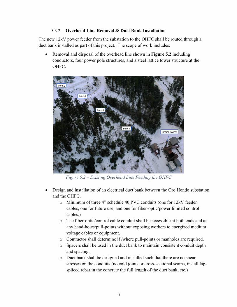
5.3.2 Overhead Line Removal & Duct Bank Installation
The new 12kV power feeder from the substation to the OHFC shall be routed through a duct bank installed as part of this project. The scope of work includes:
• Removal and disposal of the overhead line shown in Figure 5.2 including conductors, four power pole structures, and a steel lattice tower structure at the OHFC.
Figure 5.2 – Existing Overhead Line Feeding the OHFC
• Design and installation of an electrical duct bank between the Oro Hondo substation and the OHFC.
o Minimum of three 4” schedule 40 PVC conduits (one for 12kV feeder cables, one for future use, and one for fiber-optic/power limited control cables.)
o The fiber-optic/control cable conduit shall be accessible at both ends and at any hand-holes/pull-points without exposing workers to energized medium voltage cables or equipment.
o Contractor shall determine if /where pull-points or manholes are required. o Spacers shall be used in the duct bank to maintain consistent conduit depth
and spacing. o Duct bank shall be designed and installed such that there are no shear
stresses on the conduits (no cold joints or cross-sectional seams, install lap-spliced rebar in the concrete the full length of the duct bank, etc.)
17

o A #2 AWG bare copper wire shall be embedded in the duct bank concrete that runs the full length of the duct bank without splicing.
o Rock excavation: Multiple projects have excavated areas within the SURF’s surface footprint. Although bedrock is often encountered, it is fairly weathered and can be excavated with a sufficient sized machine equipped with ripper teeth and sometimes requiring jack hammering. Blasting will not be permitted. No additional payment will be made for rock excavation.
All ancillary work to complete the overhead line and duct bank work (design documents, drawings, engineering calculations, equipment sizing, procurement, installation, and deliverables listed in section 9) shall be part of the offerors scope of work.
5.3.3 Oro Hondo Fan Complex Electrical Changes
Conversion of the OHFC feeder to 12kV requires installation of new transformers and 12kV switchgear at the OHFC.
• The American Davidson fan will remain at 2400 volts and requires its own 12kV to 2400V stepdown transformer.
• The new backup fan motor voltage shall be 4160V (see detailed fan specs) and will require a 12kV to 4160V stepdown transformer.
• An existing 500kVA, 2400V to 480V transformer provides power for the Spendrup fan and miscellaneous support equipment (lighting, instruments & controls, communications, isolation gate operators, winch, etc.). This transformer will be oversized after the Spendrup fan is removed. Most of the equipment this transformer serves is in the Spendrup building which is slated to be torn down. A new 12kV to 480V (or 208V) transformer shall be installed to provide site power that is independent of the primary and backup fan power systems.
• Switchgear is required to distribute power to the OHFC transformers, provide over-current and short-circuit protection for each transformer, and provide a means to isolate one fan system from the other without affecting OHFC site power. Fused load-break switches are typically used at the 12kV distribution level at SURF.
The scope of work for electrical changes at the OHFC shall include:
• Design of the distribution system including calculations to determine appropriate sizes of transformers, conductors, conduits, and switchgear fuses.
• Design and installation of concrete equipment pads and duct banks for routing the branch circuit conductors from the switchgear to the transformers and the loads they serve. Duct banks shall include separate conduits for low voltage controls and communication cables.
• Design of a grounding grid/system for equipment bonding and personnel shock protection.
18

• Disconnection and removal of existing equipment that will be retained by SURF or must be re-installed to complete the project.
• Demolition and disposal of existing equipment that will not be retained or reused. • Procurement, delivery, and installation of new transformers. All transformers shall
be outdoor dry type, mounted on concrete equipment pads, have enclosures that provide adequate protection against rodents/wildlife, and be rated for the humid environment at the OHFC. (Dry type transformers are required because SURF environmental policy requires that any fluid containing equipment that holds more than 110 gallons of fluid shall have a secondary containment system. SURF intends to eliminate all existing fluid filled transformers as the opportunities arise.)
• Procurement, delivery, and installation of new switchgear. Switchgear may be outdoor rated or indoor rated if located inside a weather-proof structure. All switchgear shall have enclosures that provide adequate protection against rodents/wildlife and be rated for the humid environment at the OHFC.
• Service equipment for the OHFC (Panelboard, Load Center, controls, networking & communication equipment, etc.) must be located in a clean, dry environmentally controlled space. This may be a shared space with the new backup fan VFD or may be a newly established structure.
• An empty 1” electrical conduit shall run from the new Oro Hondo Backup Fan VFD to the General Electric 90/30 PLC cabinet currently installed inside the American Davidson Fan E-House for future control circuits.
• Electrical connection of all procured items to their respective equipment, and reconnection of equipment that was temporarily disconnected.
All ancillary work to accomplish the OHFC electrical changes (design documents, drawings, engineering calculations, equipment sizing, procurement, installation, and deliverables listed in Section 9) shall be part of the offerors scope of work.
Figure 5.3 is a conceptual one-line diagram to illustrate what is described in this electrical scope of work. Sizes and values shown are for illustration purposes only. The offeror is responsible for determining and verifying correct equipment sizing and ratings.
19

Figure 5.3 – Conceptual Electrical Distribution One-Line Diagram for the Oro Hondo Fans
• Exhibit 11 includes examples of transformers and switchgear that have been recently purchased and installed at SURF. The purpose is to provide guidance and potential solutions for the project. The offeror may propose other equipment or options for consideration.
20

5.3.4 Arc Flash Calculations and Labeling
All new electrical equipment and connections shall be installed in accordance with the most recent applicable codes and standards. Additionally, the offeror shall be required to perform the arc flash risk assessment calculations and apply arc flash labeling on newly installed electrical equipment and other equipment whose available fault current has been impacted by the electrical changes in this project.
The arc flash label design shall follow the SDSTA’s arc flash label design requirements provided in Exhibit 10. The SDSTA will provide copies of the facility model in SKM PowerTools format for the offeror to add to and run the arc flash calculations. The design offeror shall edit and return the modified facility SKM model back to SDSTA during project closeout.
6.0 Training
The successful offeror shall provide SDSTA personnel with training on operation and maintenance of the newly installed technologies. Training shall include the following:
6.1.1 Mechanical and electrical maintenance personnel shall receive training on the maintenance, inspection, and adjustment of the new fan system and associated equipment. Up to eight personnel will receive this training and all will attend the training sessions at the same time.
6.1.2 Electrical maintenance personnel shall receive orientation of the electrical distribution and drive systems layout and instruction on the preventative maintenance and troubleshooting of the associated control devices and equipment. Up to six electrical personnel shall receive this training and will attend the same training sessions at the same time.
6.1.3 Training materials, videos, and recorded lectures shall be provided for future refresher training and introductory training of new operators and maintenance personnel.
7.0 Submission Requirements
7.1 Submission Requirement #1
Proposals should be provided in digital format as a pdf file with standard letter size format except for general arrangement drawings. Please note there is a 50-page (8.5”x11”) limit for your response to proposal requirements (each side of a sheet of paper is a page. Use no smaller than 12-point font. Proposals must contain the following:
21

Provide a written description of the working relationship between each of the overall team members, including an organization chart. Note that the named subcontractors and outside associates or consultants must be used, and any change must be approved by the SDSTA.
Provide resumes of key personnel proposed for the contract; project manager, project superintendent, and project safety officer.
Primary points of contact from the proposed team to SDSTA.
Included in the description of the working relationship must be a detailed description on how the offeror will provide integration of pre-construction services, approach to approvals, and construction services. Also, please include a description of how the pre-construction process will transition into construction. This description should include, but is not limited to, the following items:
• How the proposed team will ensure an integrated project delivery or integrated project team process environment.
• How the offeror will integrate scheduling of the design, procurement, shop drawing, fabrication, delivery, assembly/construction and commissioning – what specific experience do the project manager(s) and superintendents(s) have working together with integrated scheduling?
• What experience does the proposed team have with design build projects?
Description of the approach to cost and schedule control. What tools are used and how is information to be communicated to the project team and SDSTA?
7.2 Submission Requirement #2
• Describe at least two example projects that deal with main ventilation fan procurement and installation that the Contractor/Subcontractor has installed and commissioned within the past 10 years. The fan power should be at least 1000 hp. Example(s) should note the customer, the location, and the date of the project(s).
7.3 Submission Requirement #3
The Offeror shall provide the information listed in the Appendix B (Bid Specification Package for The Oro Hondo Backup Fan) for evaluation.
22
7.4 Submission Requirement #4
• Describe at least two example projects that deal with electrical infrastructure that the Contractor/Subcontractor has installed/upgraded and commissioned within the past 10 years. Examples should note the customer, the location, and the date of the projects.
7.5 Submission Requirement #5
• Provide a description of the safety programs of contractors and subcontractors who would be performing work at SURF under this contract.
• Provide safety records for the past 5 years (incident/injury records, OSHA300 logs and EMR data) of contractors and subcontractors who would be performing work at SURF under this contract.
• Demonstration of the firm’s understanding and awareness of all EHS issues that will be present on this project.
7.6 Submission Requirement #6
• Provide a description of the QC programs of contractors and subcontractors who would be performing work under this contract. QC manuals will not count towards the 50-page limit.
• Demonstration of the firm’s understanding and awareness of all quality issues that will be present on this project.
7.7 Submission Requirement #7
• Provide resumes and information for the qualified professional personnel working on this project in the following key disciplines: mechanical engineering, electrical engineering, structural engineering, and civil engineering. The lead engineer in each discipline must be registered to practice in the state of South Dakota in the appropriate professional field.
7.8 Submission Requirement #8
Proposed schedule/work plan, including delivery of the work product during the design phases. Offerors shall provide the specific number of calendar days required for project completion after Notice to Proceed (ANTP).
COMPLETION DATES
Provide the specific number of calendar days required for completion after Notice to Proceed (ANTP):
Date 0 – - Notice to Proceed 0 Calendar Days ANTP
23

This milestone marks the point where work may begin
Date 1 – Conceptual 30% design submitted Calendar Days ANTP
Date 2 – Preliminary 60% design submitted Calendar Days ANTP
Date 3 – Pre final 90% design submitted Calendar Days ANTP
Date 4 – Final 100% design accepted by SDSTA 21 _ Calendar Days after 90% submittal comments
Date 5 – Shop drawings submitted Calendar Days ANTP
Date 6 – Start of installation Calendar Days ANTP
Date 7 – Project complete (total days) Calendar Days ANTP
• Total days proposed will be used to establish contract completion date.
7.9 Submission Requirement #9
This project consists of purchase and installation of a new backup underground ventilation fan and subsequent electrical infrastructure upgrades needed to support the new and existing fans at the OHFC. A detailed fixed price proposal is required and broken down below:
PRICING:
CLIN 1 - Conceptual design (30% Complete) $ FFP
CLIN 2 - Preliminary design (60% Complete) $ FFP
CLIN 3 - Pre final design (90% Complete) $ FFP
CLIN 4 - Final design (100% Complete) $ FFP
CLIN 5 - Design support services during construction $ FFP
5.1 Backup Fan Design and Procurement (total) $ FFP
Fan Assembly $ FFP
Fan Ducting $ FFP
Isolation Dampers $ FFP
Inlet and Outlet Cones $ FFP
Fan motor $ FFP
24

Drive Shaft $ FFP
VFD and Controls $ FFP
Instrumentation $ FFP
5.2 Fan Installation (total) $ FFP
Excavation and site prep $ FFP
Installation of fan package $ FFP
Site restoration and cleanup for 5.1, 5.2, & 5.3 $ FFP
5.3 Electrical Distribution Reconfiguration (total) $ FFP
Oro Hondo Substation Changes $ FFP
Overhead Line Removal $ FFP
Duct Bank Installation $ FFP
OHFC Electrical Changes $ FFP
Arc Flash Calculations and Labeling $ FFP
Commissioning for 5.1, 5.2, & 5.3 (inc. as-built drawings, O&M manuals, and training) $ FFP
TOTAL PROPOSAL - $ FFP
The offeror fixed price shall constitute full payment for the work, materials, services, quality control testing, other items required, and include all applicable federal, state use, sales, and local taxes, duties, permits, and all the Subcontractor's other obligations related to such work.
7.10 Submission Requirement #10
All offerors are required to attend a mandatory site visit May 25, 2021 from 10:00-12:00 p.m. MT at the SURF, 630 East Summit Street, Lead South Dakota. Pre-registration is required email [email protected] by close of business May 21, 2021 to receive instructions and directions. Only companies represented at the pre-proposal conference will
25

be eligible to submit proposals. Contractors’ subcontractors are encouraged, but not required, to attend.
Offerors should submit an electronic copy (pdf format) of the proposal no later than 2:00 p.m. on June 21, 2021 to [email protected]. Late submissions will not be accepted.
Questions need to be submitted by June 1, 2021.
Questions/Answers will be emailed to all prospective proposals and posted to the sanfordlab.org website no later than June 4, 2021.
The proposal period may be extended at the discretion of SDSTA based on the quantity and/or complexity of questions. Any notices of extension of time to respond will be distributed to all prospective Offerors by SDSTA.
All communications regarding this procurement between RFP release and award shall be directed by email to [email protected]. Communications with other SDSTA staff regarding this procurement in advance of the award are not allowed.
8.0 Technical Evaluation Criteria
8.1 The evaluation criteria for this project are listed below in descending order of importance (first by major criterion and then by each sub- criterion).
8.2 The Offeror’s proposed fan solution including performance characteristics, general arrangement drawings and other technical requirements referenced in Appendix B.
8.3 Specialized experience and technical competence in: (1) Primary fan design fabrication and installation. (2) Design and Installation of industrial electrical equipment.
8.4 Construction safety practices and procedures, and safety record relating to industrial and electrical equipment installation.
8.5 Qualified professional personnel in the following key areas: design development, project management, project supervision, heavy construction of industrial and electrical equipment.
8.6 Past performance on SDSTA, US Dept of Energy, State of South Dakota or other contracts with respect to cost control, quality of work, and compliance with performance schedules.
The best value source selection process will be used for awarding this contract. Selection will be made based on tradeoffs among price and non-price evaluation criteria.
26

9.0 Administrative Requirements
9.1 Technical – The successful offeror shall identify all technical interfaces required for the project. The successful offeror shall obtain approval and coordinate closely with SDSTA in all phases of the project to assure compatibility with the technical requirements.
9.2 Meetings – In keeping with the terms and conditions of the contract, project meetings shall be held at SURF and made available by teleconference for participants that cannot attend in person. Meetings will include the following:
9.2.1 A pre-construction conference shall occur prior to the commencement of the design phase of the project. Key personnel from SDSTA, and the successful offeror’s project manager and lead designers assigned to the project shall participate in the design kick-off meeting.
9.2.2 Bi-weekly progress meetings shall be held, by teleconference, during the design phase of the project to report design status and discuss, clarify, and respond to RFI’s.
9.2.2.1 A separate preconstruction meeting shall be held prior to the kickoff of construction.
9.2.3 Weekly onsite progress meetings shall be held during site construction work. Meetings shall include but are not limited to: updated project schedules with three-week look ahead, quality control, manpower and safety reports.
9.3 Daily Coordination – Daily coordination is required during site work at SURF, including check-in/check-out, successful offeror vehicle and equipment parking, and the delivery, loading/unloading and laydown of materials. Minimal interruption to SURF operations and projects performed by others is required.
10.0 Deliverables
At the completion of the project SDSTA requires the following deliverables:
10.1 Oro Hondo Fan Site Design
10.1.1 Deliverables for the design are described in section 4.0 of this document and include design documents at 30%, 60%, 90% and 100% design completion
10.2 Fabrication, Procurement, and Installation
10.2.1 All scope items performance tested by successful offeror and accepted by SDSTA to ensure that the primary and secondary fans can operate safely at their rated capacities.
10.2.2 Electrical load flow, coordination, and arc-flash study reports, submitted in SKM Power Tools file format.
27

10.2.3 All equipment and systems correctly identified and labeled per applicable codes and standards.
10.2.4 All final as-built electrical, mechanical, and structural drawings shall be submitted in both Adobe .pdf and AutoCAD formats.
10.2.5 “For Construction” and final “As-built” drawings shall be certified and stamped by a Professional Engineer registered in the state of South Dakota.
10.2.6 Critical spare parts list for planning purposes that includes itemized pricing, availability, and estimated delivery times.
10.2.7 O&M Manuals shall be submitted in clear, legible, and searchable Adobe PDF format.
10.2.8 Completed mechanical and electrical maintenance personnel training.
10.2.9 Copies of all training materials developed by the successful offeror and used for training of SDSTA operator and maintenance personnel.
10.2.10 Final commissioning report shall include:
10.2.10.1 Voltage and, current measurements on both line side of VFD system and at motor terminals
10.2.10.2 Verification of the function and operation of all safety features and equipment
10.2.10.3 Performance test data including verification of fan performance.
11.0 Additional Requirements
In addition to the above requirements all work performed on SDSTA property must be performed in accordance with SDSTA’s Division 1 specifications (Exhibit 12).
28

29

Bid Specification Package for
The Oro Hondo Backup Fan
Prepared for
South Dakota Science and Technology Authority Sanford Underground Research Facility
630 E. Summit St Lead, SD 57754
USA
Prepared by
3277 Garth Rd Charlottesville, VA 22901 www.vi-ventilation.com on April 26th, 2021
30

TABLE OF CONTENTS
Introduction ......................................................................................................................... 1
Site Excavation and Preparation ......................................................................................... 2
Site Electrical and Power Supply ........................................................................................ 2
Fan, Ductwork and Sound Attenuation ............................................................................... 2
4.1 Product and Design Requirements ....................................................................... 3
4.2 Fan System Performance Requirements .............................................................. 4
4.3 Fan Motor Specifications ..................................................................................... 6
4.4 Instrumentation..................................................................................................... 6
4.5 Special Considerations ......................................................................................... 7
Delivery and Handling ........................................................................................................ 7
Bid Organization & Interested Vendor List ........................................................................ 8
31

Introduction This package covers the requirements for the procurement of a new fan that will be installed
at the existing Oro Hondo Fan Complex (OHFC) that connects to the Sanford Underground
Research Facility (SURF) operated by the South Dakota Science and Technology
Authority (SDSTA) and located in in Lead, South Dakota.
The SURF requires a new surface fan installation in support of its continuing operations
and expansion. The new fan installation will consist of a fan installed with a Variable
Frequency Drive (VFD) and in parallel with the existing Oro Hondo Fan in such a manner
that one fan may be used as the primary ventilation supply with the other providing full
redundancy as needed.
Each fan should have complete plan and sectional “General Arrangement” drawings
provided to SDSTA at the time the quotation is submitted. The drawings provided should
include all relevant structure(s) associated with the installation, including but not limited
to foundation requirements (where applicable), inlet cones and evasés, motors, screens,
isolation dampeners, silencers, etc. Motors, drives and any required ductwork should also
be included in the quotation, as should any site preparation (excavation, soil compaction,
concrete foundation work, etc.). It is expected that any recommended ductwork will be
optimized for the specific site characteristics utilizing CFD or other similar software to
minimize the energy consumption of the operating fan.
This work will also include the expansion/replacement of the electrical infrastructure
between the fan substation and the fan site in support of the existing American Davidson
(AD) Fan and the proposed Oro Hondo Backup (OHB) Fan.
The bidder should also include an estimate for on-site consultation, shipping, construction,
and commissioning of the fan installation as required.
32

Site Excavation and Preparation The replacement of the OHBF and any associated electrical upgrades will require some
excavation and alteration of the existing OH Fan site, including the expansion of the
laydown area, demolition of existing infrastructure (e.g., fans, ductwork, etc.) and
installation and support of the new fan, motor and ductwork.
Any successful proposal will include all required site work, including excavation, soil
compaction, demolition and removal of redundant infrastructure and concrete/foundation
work required to support the new OHBF installation.
Additional site information and details can be found in the Oro Hondo Backup Fan RFP.
Site Electrical and Power Supply As part of the OHB fan project, the electrical infrastructure from the substation to the Oro
Hondo Raise / AD fan site will be replaced.
The current AD fan drive accepts 2300V, and the power delivery system installed much
accommodate this and the 4160V drive voltage for the new fan (proposed OHB fan).
The proposed OHB fan installation should include a suitably-sized Allen-Bradley
Powerflex 7000 Variable Frequency Drive (VFD).
Additional details of the Oro Hondo Raise site power delivery system can be found in the
Oro Hondo Backup Fan RFP.
Fan, Ductwork and Sound Attenuation The OHB fan and associated ductwork required for connection to the Oro Hondo Exhaust
Raise and SURF ventilation system constitute the principal component of this project.
33

The following sections cover required components of the proposed OHB fan and duct
installation. Additional information and technical specifications can be found in
Addendum A.
In the case that deviation from any required technical specification(s) or procedures is
requested by the provider, permission from SDSTA personnel must be provided, in writing,
prior to their inclusion in the proposal.
4.1 Product and Design Requirements
Fan manufacturer shall provide design recommendations (drawings) for fan foundation,
motor foundation, and other structural support.
In order to support the fan testing and operation, the fan installation/ductwork should
include the ability to both isolate and short-circuit the fan.
Fan manufacturer shall provide a list of recommended shop and field testing and
maintenance procedures.
Fan manufacturer shall provide a representative for the on-site supervision of fan
installation and testing.
Fan manufacturer representative shall be available until the fan is running within desired
performance limits on quantity, pressure, vibration, temperature, sound, instrumentation
calibration, etc.
The primary components of each specified fan installation shall have an expected life-span
of twenty (20) years.
34

4.2 Fan System Performance Requirements
A detailed list of Fan Specification Data Sheets (FSDS) for each individual
faninstallation may be found in Addendum A.
Before shipment, each fan should be tested in accordance with the Air Movement and
Control Association International, Inc. (AMCA) Standard 210 and AMCA Publication 802
(or similar). The Fan manufacturer shall contact SDSTA personnel prior to testing in order
to allow for the observation of the fan testing if desired. All fans should be guaranteed to
deliver the specified airflow at the given pressure under post-installation conditions. The
fan will also be required to meet the specified operating point(s) while operating under the
site noise limit of 85 decibels (dB).
Fan manufacturer shall provide the following information for each fan or set of fans
specified.
• Inlet components
• Outlet components
• Noise limits and profiles
• Isolation system(s)
Fan manufacturer shall provide information on the corrosion and abrasion resistance of
each fan specified. The air exhausted by the fan will contain normal amounts of suspended
particles as associated with underground environments (i.e., dust, humidity).
Fan manufacturer shall find the following fan performance criteria for each fan installation
as specified on the Fan Specification Data Sheet.
• Fan operating point(s) or range
• Total pressure
• Volumetric flow rate
35

• Nominal air density
• Fan efficiency targets
Fan pressures referenced on the Fan Specification Data Sheet (FSDS) are for delivered fan
pressure. It is the responsibility of the Fan manufacturer to account for any and all pressure
increases associated with the fan, inlet and outlet losses, ducting, and installation structures.
Where two parallel fans are recommended, Fan manufacturer shall verify the suitability of
the fans for parallel operation. All such fans shall operate at a stable point of the fan curve
during both single and parallel operation.
Fan manufacturer shall provide information regarding the life expectancy of the fan
bearings, lubrication requirements, and associated maintenance standards.
Fan manufacturer shall specify the fan critical speed with respect to design speed.
Limitations of static or dynamic imbalance, eccentricity and wobble shall also be provided.
All fan components such as motor(s), motor control center, shaft bearings and others shall
be provided with a cover as necessary.
For axial fans, the wheel track shall be constructed in such a manner as to allow the pitch
of the blades to be manually adjusted while at rest through an access door or hatch, unless
automatic blade adjustment is provided.
The hub shall be indexed in blade angle settings corresponding to the blade angle setting
shown on the provided fan curve(s).
Fan manufacturer shall include an inlet/outlet screen for all specified fans.
All specified fans and associated ducting shall include attached grab-points for installation
and maintenance purposes.
36

4.3 Fan Motor Specifications
Fan manufacturer shall provide information regarding the voltage, current, frequency, and
phases of fan motors.
Fan manufacturer shall provide information regarding motor enclosure and cooling types.
Fan manufacturer shall provide information regarding motor starter type and transformer
limits.
Any, and all installed transformers shall be “dry” type.
Fan manufacturer shall provide information regarding matched motor and fan torque
capacities.
Fan manufacturer shall make recommendations for appropriate capacitors if necessary, to
correct the power factor at full load.
All fans specified should be capable of start-up under full pressure load.
All fans specified shall be capable of operating on a 4160V system with the required
transformer to be specified (from the site voltage of 12 kV).
Fan manufacturer shall provide an Allen Bradley Powerflex 7000 variable frequency drive
(VFD) as well as compatible equipment (motors, etc.) where necessary.
4.4 Instrumentation
SDSTA uses the Maestro Digital Mine series of instrumentation throughout the facility,
and will require any proposed fan installation to include this brand/type of instrumentation
in order to provide a seamless integration into the existing SURF network.
37

Fan manufacturer shall provide remote monitoring capability and equipment where noted
on the Fan Specification Data Sheet for the following items (at a minimum):
• Fan bearing vibration
• Fan and motor bearing temperature
• Motor winding temperature
• Fan static pressure
• Fan flow volume
• CO content of air at the fan (ppm)
• Inlet and outlet psychrometric data (barometric pressure, temperature and
humidity)
Fan manufacturer shall provide a system capable of permanently recording or digitally
archiving the fan monitoring data as listed above.
4.5 Special Considerations
Fan manufacturer shall provide a list of recommended spare parts for each installation with
individual prices, to include at a minimum:
• One (1) balanced rotor hub assembly
• One (1) set of blades and associated hardware
• One (1) motor in accordance with the motor specification
Delivery and Handling Fan manufacturer shall specify the earliest on-site delivery date from time of purchase
order.
Fan manufacturer shall specify the recommended unloading, storage and handling
procedures for all equipment specified.
38

Pricing is to be FOB Oro Hondo fan site (freight allowed).
Bid Organization & Interested Vendor List
Fan manufacturer shall include the following information in its bid response:
• Complete description and pricing for each fan installation.
• Complete description and pricing for all associated options.
• General layout plan and profile drawings for each installation.
• The following information should be provided for each installation:
- Size of fan(s)
- Number of blades
- Design operating points and conditions (performance curves)
- Noise profile information
- Materials of construction for all major components
- Blade adjustment details
- Type and application of required lubricants
- Type and size of bearings
- Type and description of drive shaft components
- Motor type, manufacturer, ratings, and other technical information
- Description of all relating ducting, inlet and outlet cones, isolation
dampers, etc.
- Paint and finish of equipment
- Description of monitoring and instrumentation
Fan manufacturer shall provide unit costs for the following:
• Fan assembly
• Fan ducting
39

• Isolation dampers
• Fan motor
• Drive shaft
• Motor starter and controls
• Instrumentation
• Recommended spare parts
• Testing, start-up and commissioning assistance
Any questions regarding the scope or requirements of this project should be submitted in
writing [email protected] no less than two weeks before the bid due date in
accordance with the bid specifications outlined in the Bid Document.
As an additional resource for interested bidders, an alphabetical list of interested fan
suppliers and their point of contact are provided below:
1. ABC Ventilation Systems
Michael Schulte
2. Clarage Industrial Fans & Services
Tyler Moulton
3. Howden
Shane Reimer
shane@[email protected]
4. Hurley Ventilation Technologies
Bart Hurley
40

5. Joseph B. Johnson, LLC
Tony Mackinnon
6. Minetek
Remy Bourcier
7. Robinson Fans
Wade Sears
8. Spendrup Fan Company
Jens Spendrup
9. TLT Turbo
Reggie Barry
10. Zitron
Louis Van Wyk
41

Addendum A
Fan Specification Data Sheets (FSDS)
42

Section / Description UnitsIDENTIFICATIONEquipment Type text
Equipment Name text
Equipment Number text
Quantity #Country of Manufacture textManufacturer textModel No. textREFERENCESEquipment Technical Specification Section textBill of Materials textInstallation, Operation and Maintenance Manuals textPainting and Coating Standard textSITE CONDITIONSElevation / Air Density textLocation (Indoors / Outdoors) textPotential Ambient Temperature Min °C Dry BulbPotential Ambient Temperature Max °C Dry BulbFAN DUTY Service textDuty textOperating Mode Duty / StandbyFan Inlet Density lb/ft3
Nominal Duty: Operating Point 1
Operating Point 2
Operating Point 3
Operating Point 4 - Operating Point
1Operating Point
2Operating Point
3Operating Point
4Actual Inlet Flow Rate at mine density 265000 395000 465000 - cfmCollar Pressure (Total) 8.8 17.9 15.7 - inches w.g.Design Duty: - - - -Actual Inlet Flow Rate 278250 414750 488250 - cfmMine Static Pressure 9.8 19.9 17.4 - inches w.g.System Pressure Losses As per Manf. As per Manf. As per Manf. As per Manf. inches w.g.
Entrance Loss As per Manf. As per Manf. As per Manf. As per Manf. inches w.g.Inlet Screen Loss As per Manf. As per Manf. As per Manf. As per Manf. inches w.g.Inlet Bell Loss As per Manf. As per Manf. As per Manf. As per Manf. inches w.g.Inlet Silencer Loss, if required As per Manf. As per Manf. As per Manf. As per Manf. inches w.g.Outlet Silencer Loss, if required As per Manf. As per Manf. As per Manf. As per Manf. inches w.g.Transition Piece(s) Loss As per Manf. As per Manf. As per Manf. As per Manf. inches w.g.Flexible Connection Loss As per Manf. As per Manf. As per Manf. As per Manf. inches w.g.Damper Loss As per Manf. As per Manf. As per Manf. As per Manf. inches w.g.Evasé/Diffuser Loss As per Manf. As per Manf. As per Manf. As per Manf. inches w.g.Outlet Screen Loss As per Manf. As per Manf. As per Manf. As per Manf. inches w.g.Exit Loss As per Manf. As per Manf. As per Manf. As per Manf. inches w.g.System Effect Loss As per Manf. As per Manf. As per Manf. As per Manf. inches w.g.Other(s), please specify As per Manf. As per Manf. As per Manf. As per Manf. inches w.g.
Fan Pressure (Static Pressure + System Pressure Losses) As per Manf. As per Manf. As per Manf. As per Manf. inches w.g.Power Required at Fan Shaft As per Manf. As per Manf. As per Manf. As per Manf. bhpFan Static Efficiency As per Manf. As per Manf. As per Manf. As per Manf. %Fan Total Efficiency As per Manf. As per Manf. As per Manf. As per Manf. %Required Fan Blade Setting As per Manf. As per Manf. As per Manf. As per Manf. DegPercent of Peak Blade Pressure (Maximum 80%) As per Manf. As per Manf. As per Manf. As per Manf. %Operating Speed As per Manf. As per Manf. As per Manf. As per Manf. RPMFirst Critical Speed RPMFirst Critical Speed Safety Factor vs Maximum Operating Speed %Tip Speed As per Manf. As per Manf. As per Manf. As per Manf. fpmHalf or Full Impeller Blades By Vendor By Vendor By Vendor By Vendor Half / FullNumber of Stages By Vendor By Vendor By Vendor By Vendor #Motor Rated Power bhpMotor Load By Vendor By Vendor By Vendor By VendorAbsorbed Power By Vendor By Vendor By Vendor By Vendor bhpPower Factor By Vendor By Vendor By Vendor By Vendor -Fan Motor Voltage VStarter Type textVFD Input Voltage VMotor Efficiency By Vendor By Vendor By Vendor By Vendor %
Overall Efficiency (Motor and Fan Static Efficiencies) By Vendor By Vendor By Vendor By Vendor %Overall Efficiency (Motor and Fan Total Efficiencies) By Vendor By Vendor By Vendor By Vendor %
MECHANICAL COMPONENTSFan Type textFan Arrangement textMounting Arrangement textBlade Type textQuantity of Impeller Blades #Access Doors (number and location) textImpeller Hand Brake textBearings -
Manufacturer textModel textL10 Life hoursSeals text
Lubrication System (Auto/Manual) textLubrication Type (Oil/Grease) textFlexible Element Type textCoupling -
Manufacturer textModel textType text
Isolation Damper Type textNoise Control -
If Required Yes/NoType text
Drain -Size mmLocation(s) text
Shaft Blocking for Transport text
Oro Hondo Backup FanFan Specification Data SheetPrimary Fan - Surface Installation
SDSTA
As per Manf.As per Manf.
-
Inlet Outlet
As per Manf.As per Manf.As per Manf.As per Manf.
-As per Manf.As per Manf.
Disc PackRequired, automatic open/close actuation
-
---
----
-
As per Manf.As per Manf.As per Manf.
As per Manf.
Centrifugal or Axial Fan
Oro Hondo Backup Fan
XXX.XX
1 / 2As per Manufacturer (Manf.)
As per Manf.As per Manf.
By Vendor, Minimum 130%
Horizontal; Skid-mounted suitable for suspension from back
100,000
As per Manf.
4160
As per Manf.
VFDAs per Manf.
As per Manf.
As per Manf.As per Manf.As per Manf.
Required-
As per Manf.As per Manf.
4950 ft above sea levelSurface (ambient outdoors)
- 25+ 38
Mine AirContinuous, 24 Hrs per day
Duty0
Project Design from Manufacturer
---
-
-
-
Inlet Outlet
-
-
-
Page 1 FSDS_SDSTA_OroHondo_Rev043

Section / Description Units
Oro Hondo Backup FanFan Specification Data SheetPrimary Fan - Surface Installation
SDSTA
Project Design from ManufacturerELECTRICAL COMPONENTSDrive Type textMotor -
SSA Manufacturer textSSA Model textNameplate Power bhpFan Motor Power Safety Factor vs Maximum Fan Duty BHP %
Speed RPMEnclosure IPVolts/Phase/Frequency V / - / Hz
Starter / Variable Frequency Drive textSSA Manufacturer textSSA Model text
Fan Speed Sensor and Transmitter textType textSSA Manufacturer textSSA Model text
Damper Actuator -Type textManufacturer textModel text
Damper Positioner -Type textSSA Manufacturer textSSA Model text
Hand Brake Position -Type textSSA Manufacturer textSSA Model text
Condition Based Monitoring Instrumentation: Required Position Critical Qty per Unit -
Bearing Temperature Sensor and TransmitterSensors Only,
Transmitters By Others
Inboard and outboard Yes 2 text
Bearing Vibration Sensor and TransmitterSensors Only,
Transmitters By Others
Inboard and outboard Yes 2 text
Other(s), please specify textINFRASTRUCTUREHousing textShaft textHub textBlades textNoise Control -
Frame textAcoustic Media text
Flexible Element -Frame textFlexible Material text
Damper textEvasé textLining Material -
Impeller textHousing text
Other (Please Specify) textENVIRONMENTAL PROTECTION / COATINGSSurface Preparation textPrimer textFinish Coat text
As per Manf.
As per Manf., Minimum 10%
As per Manf.NEMA 4x
Direct drive-
As per Manf.As per Manf.
4160 V / 3 phase / 60 HzRequired (Optional price)
As per Manf.As per Manf.As per Manf.As per Manf.As per Manf.As per Manf.
RequiredElectric, automatic isolation open/close
As per Manf.As per Manf.
Required, Open / ClosedAs per Manf.
-As per Manf.As per Manf.
-As per Manf.As per Manf.As per Manf.
As per Manf.As per Manf.
Required, Engaged / DisengagedAs per Manf.As per Manf.As per Manf.
By Vendor
As per Manf.As per Manf.
As per Manf.As per Manf.As per Manf.
As per Manf.As per Manf.
As per Manf.As per Manf.As per Manf.
As per Manf.-
-
-
Manufacturer / Model Comments
-
-
-
-
-
-
---
-
Page 2 FSDS_SDSTA_OroHondo_Rev044

Section / Description Units
Oro Hondo Backup FanFan Specification Data SheetPrimary Fan - Surface Installation
SDSTA
Project Design from ManufacturerPHYSICAL PARAMETERSFan Diameter inchesHousing Thickness inchesImpeller Diameter inchesBlade Thickness inchesShaft -
Diameter inchesLength inches
Inlet Bell -Inlet Diameter inchesThickness inches
Silencers, if required -Inlet Silencer Diameter inchesOutlet Silencer Diameter inches
Flexible Connection Diameter inchesDamper Diameter inchesEvasé -
Outlet Diameter inchesThickness inches
Corrosion Allowance Thickness inchesWear Lining Material -
Impeller Thickness inchesHousing Thickness inches
Overall Assembled Dimensions -Length inchesWidth inchesHeight inches
Total Installed Weight lbMax Lift For Maintenance (Identify) lb / textTotal Shipping Weight lbOperating Weight lbDry Weight lbMotor Weight lbSOUNDA-Weighted Time-Averaged Emission Sound Pressure Level at 1m
Operating Point 1
Operating Point 2
Operating Point 3
Operating Point 4 - Operating Point
1Operating Point
2Operating Point
3Operating Point
4Unsilenced As per Manf. As per Manf. As per Manf. As per Manf. dBASilenced <85 <85 <85 <85 dBA
PERFORMANCE AND TESTINGFan Performance textResonant Speed Analysis textBearing Temperature and Vibration textMotor Operating Power textNoise Level textVibration textOther(s), please specify textRELIABILITY, MAINTENANCE AND WARRANTIES
Failure Mode: Mean Time to Repair (MTTR)
Mean Time Between
Failures (MTBF)
"Total Downtime Over 10 year
period"- Mean Time to
Repair (MTTR)
Mean Time Between
Failures (MTBF)
"Total Downtime Over 10 year
period"Comments
Bearing wear As per Manf. As per Manf. As per Manf. hrsFan blades crack As per Manf. As per Manf. As per Manf. hrsDrive coupling wear As per Manf. As per Manf. As per Manf. hrsFlexible connection wear As per Manf. As per Manf. As per Manf. hrsFan imbalance As per Manf. As per Manf. As per Manf. hrsMotor bearing failure As per Manf. As per Manf. As per Manf. hrsMotor seal failure As per Manf. As per Manf. As per Manf. hrsStarter/VFD wear As per Manf. As per Manf. As per Manf. hrsFan wear (rotor, runner, inlet bell) As per Manf. As per Manf. As per Manf. hrsAnticipated life of equipment As per Manf. As per Manf. As per Manf. hrs
Vendor to identify other failure modes, and add to As per Manf. As per Manf. As per Manf. hrsthis section as appropriate. As per Manf. As per Manf. As per Manf. hrs
Assembly Based Replacement Strategy textMinimum Mechanical Availability %
Manufacturer to supply fan performance curves covering all specified flow conditions.Provider shall fill out all cells highlighted grey in 'Providor Data' column and return with bid submission.
As per Manf.By Vendor, Minimum 0.25
As per Manf.Vendor to Specify if Required
As per Manf.As per Manf.
-As per Manf.As per Manf.As per Manf.As per Manf.As per Manf.As per Manf.As per Manf.As per Manf.
As per Manf.By Vendor, Minimum 0.25
As per Manf.As per Manf.
-As per Manf.As per Manf.
-As per Manf.As per Manf.
-As per Manf.As per Manf.As per Manf.As per Manf.
-
As per Manf.
As per Manf.
As per Manf.99%
-
-
-
-
-
Page 3 FSDS_SDSTA_OroHondo_Rev045