solutions manual for design of structural elements, · pdf file · 2016-03-14- iii...
TRANSCRIPT
SOLUTIONS MANUAL FOR
Design of Structural Elements,
3rd edition
By
Chanakya Arya
- ii -
CRC Press Taylor & Francis Group 6000 Broken Sound Parkway NW, Suite 300 Boca Raton, FL 33487-2742 © 2009 by Taylor & Francis Group, LLC CRC Press is an imprint of Taylor & Francis Group, an Informa business No claim to original U.S. Government works Printed on acid-free paper Version Date: 20130124 International Standard Book Number-13: 978-0-415-46720-9 (Paperback) This book contains information obtained from authentic and highly regarded sources. Reasonable efforts have been made to publish reliable data and information, but the author and publisher cannot assume responsibility for the validity of all materials or the consequences of their use. The authors and publishers have attempted to trace the copyright holders of all material reproduced in this publication and apologize to copyright holders if permission to publish in this form has not been obtained. If any copyright material has not been acknowledged please write and let us know so we may rectify in any future reprint. Except as permitted under U.S. Copyright Law, no part of this book may be reprinted, reproduced, transmitted, or utilized in any form by any electronic, mechanical, or other means, now known or hereafter invented, including photocopying, microfilming, and recording, or in any information storage or retrieval system, without written permission from the publishers. For permission to photocopy or use material electronically from this work, please access www.copyright.com (http://www.copyright.com/) or contact the Copyright Clearance Center, Inc. (CCC), 222 Rosewood Drive, Danvers, MA 01923, 978-750-8400. CCC is a not-for-profit organization that provides licenses and registration for a variety of users. For organizations that have been granted a photocopy license by the CCC, a separate system of payment has been arranged. Trademark Notice: Product or corporate names may be trademarks or registered trademarks, and are used only for identification and explanation without intent to infringe. Visit the Taylor & Francis Web site at http://www.taylorandfrancis.com and the CRC Press Web site at http://www.crcpress.com
- iii -
This manual has been prepared for use in conjunction with the textbook Design of Structural Elements, Third edition, covering the problems in chapters 2-6, particularly for use by course instructors. Chapter 2 ............................................................................................................ 1 Chapter 3 ............................................................................................................ 6 Chapter 4 .......................................................................................................... 12 Chapter 5 .......................................................................................................... 17 Chapter 6 .......................................................................................................... 20
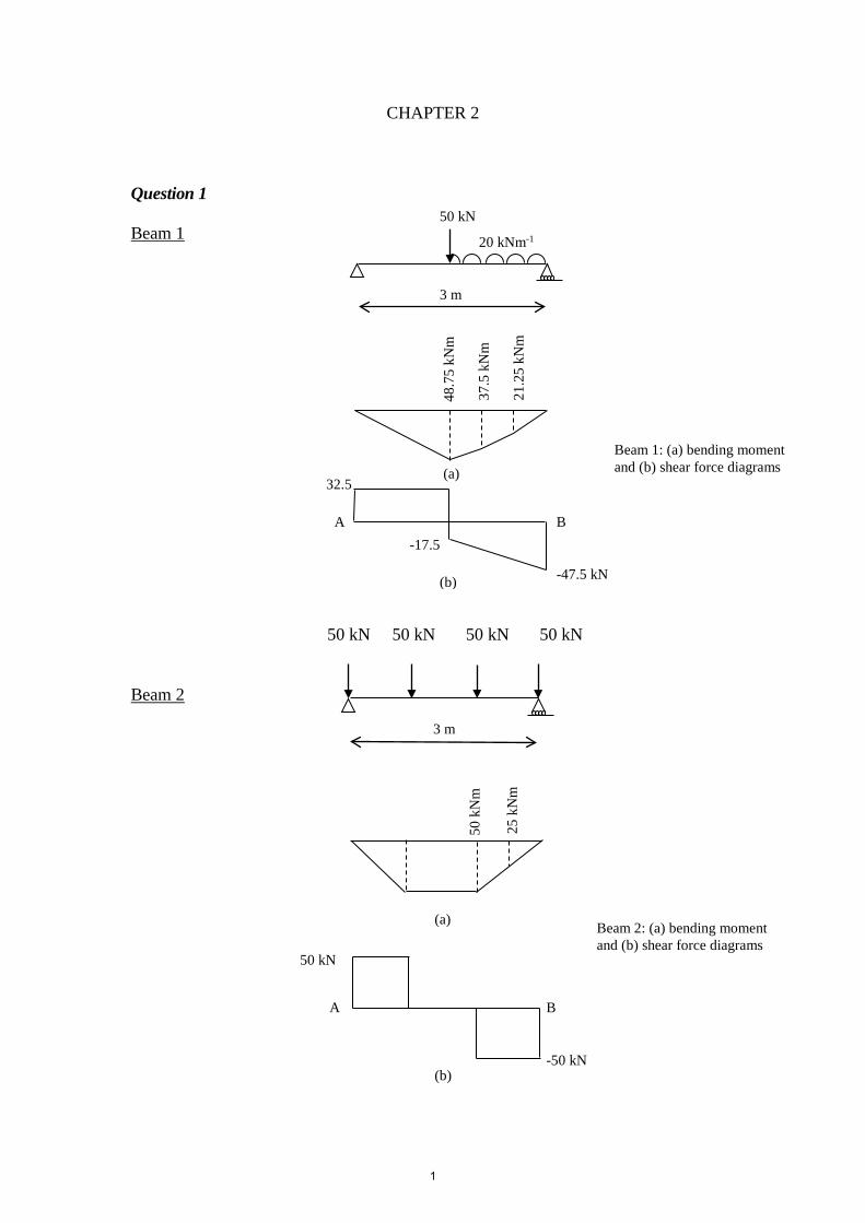
CHAPTER 2 Question 1 Beam 1 50 kN 50 kN 50 kN 50 kN Beam 2
(a)
3 m
20 kNm-1
50 kN
3 m
B A
-50 kN
25
kNm
50 k
Nm
B A -17.5
-47.5 kN
32.5
21.
25 k
Nm
37.
5 kN
m
48.
75 k
Nm
50 kN
Beam 1: (a) bending moment and (b) shear force diagrams
(b)
(a)
(b)
Beam 2: (a) bending moment and (b) shear force diagrams
1
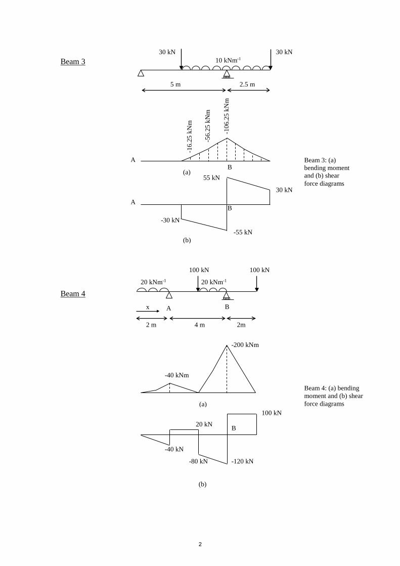
Beam 3 Beam 4
A
30 kN 30 kN
5 m 2.5 m
10 kNm-1
B
-120 kN -80 kN
20 kN
-40 kN
100 kN
-200 kNm
-40 kNm
20 kNm-1 20 kNm-1
100 kN 100 kN
55 kN
B A
-30 kN
-55 kN
30 kN
-106
.25
kNm
-56.
25 k
Nm
-16.
25 k
Nm
B A
2 m 4 m 2m
B x
(a)
(b)
Beam 3: (a) bending moment and (b) shear force diagrams
(a)
(b)
Beam 4: (a) bending moment and (b) shear force diagrams
2
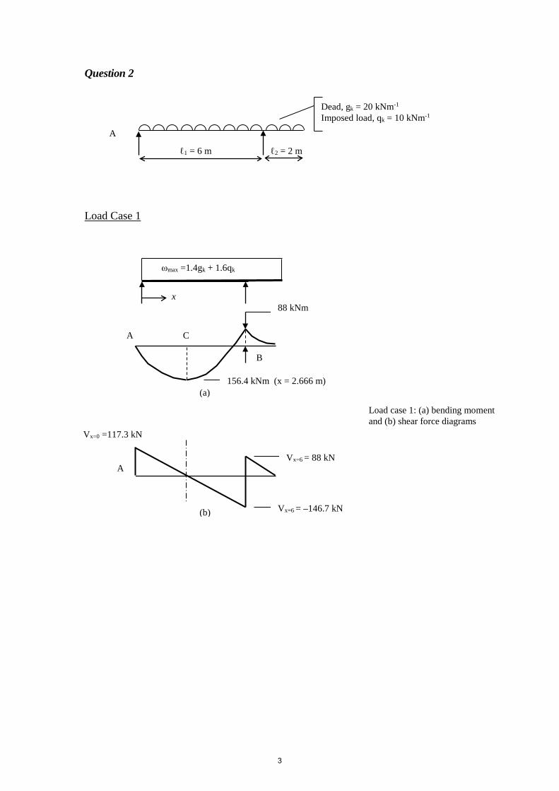
Question 2 Load Case 1
(a)
A
Vx=0 =117.3 kN
156.4 kNm (x = 2.666 m)
C
B
A Vx=6 = 88 kN
Vx=6 = –146.7 kN
ωmax =1.4gk + 1.6qk
x
ℓ2 = 2 m
Dead, gk = 20 kNm-1 Imposed load, qk = 10 kNm-1
ℓ1 = 6 m
A
(b)
Load case 1: (a) bending moment and (b) shear force diagrams
88 kNm
3
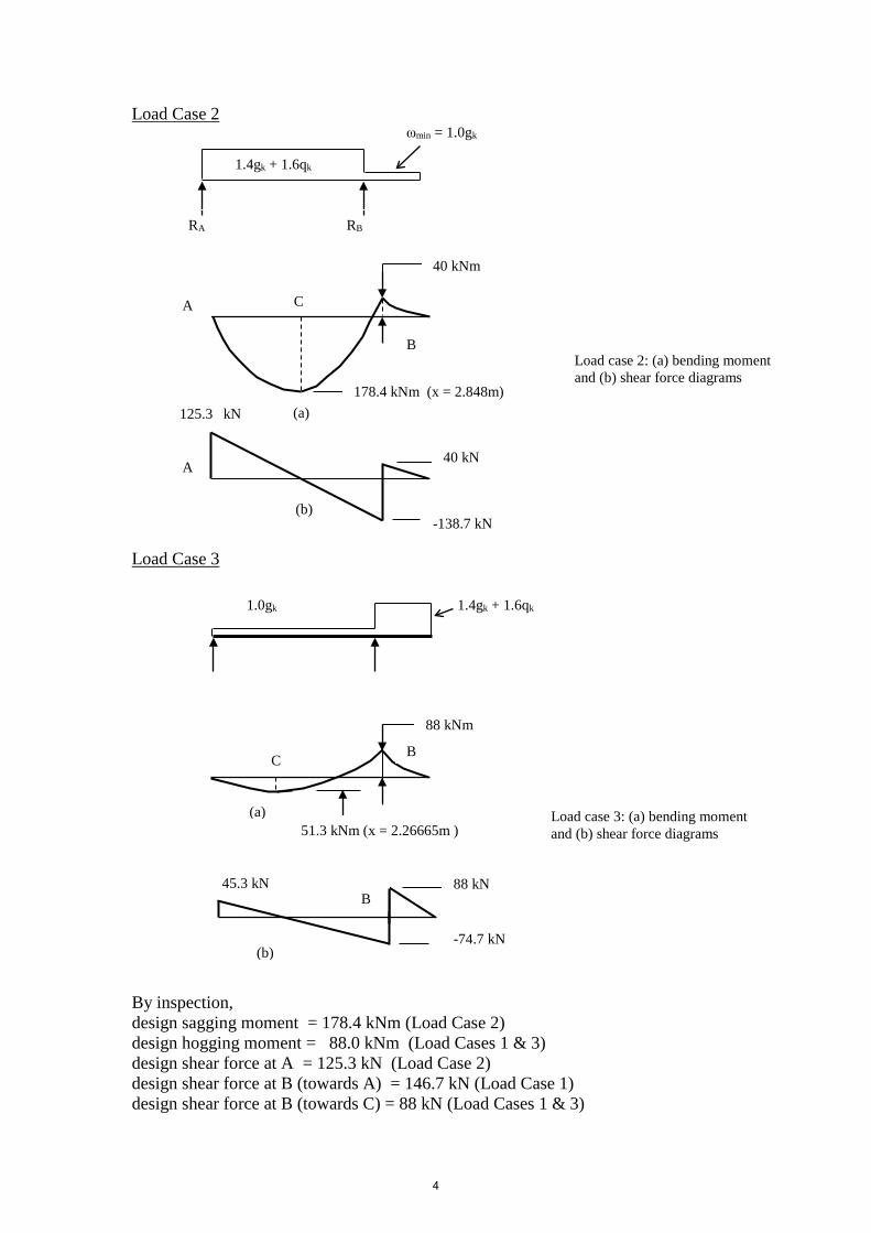
Load Case 2 Load Case 3 By inspection, design sagging moment = 178.4 kNm (Load Case 2) design hogging moment = 88.0 kNm (Load Cases 1 & 3) design shear force at A = 125.3 kN (Load Case 2) design shear force at B (towards A) = 146.7 kN (Load Case 1) design shear force at B (towards C) = 88 kN (Load Cases 1 & 3)
125.3 kN
(b)
C
178.4 kNm (x = 2.848m)
40 kNm
A
B
A 40 kN
-138.7 kN
ωmin = 1.0gk
1.4gk + 1.6qk
1.4gk + 1.6qk 1.0gk
RA RB
(a)
Load case 2: (a) bending moment and (b) shear force diagrams
C
88 kNm
B
(a)
45.3 kN 88 kN
-74.7 kN
B
(b)
51.3 kNm (x = 2.26665m ) Load case 3: (a) bending moment and (b) shear force diagrams
4
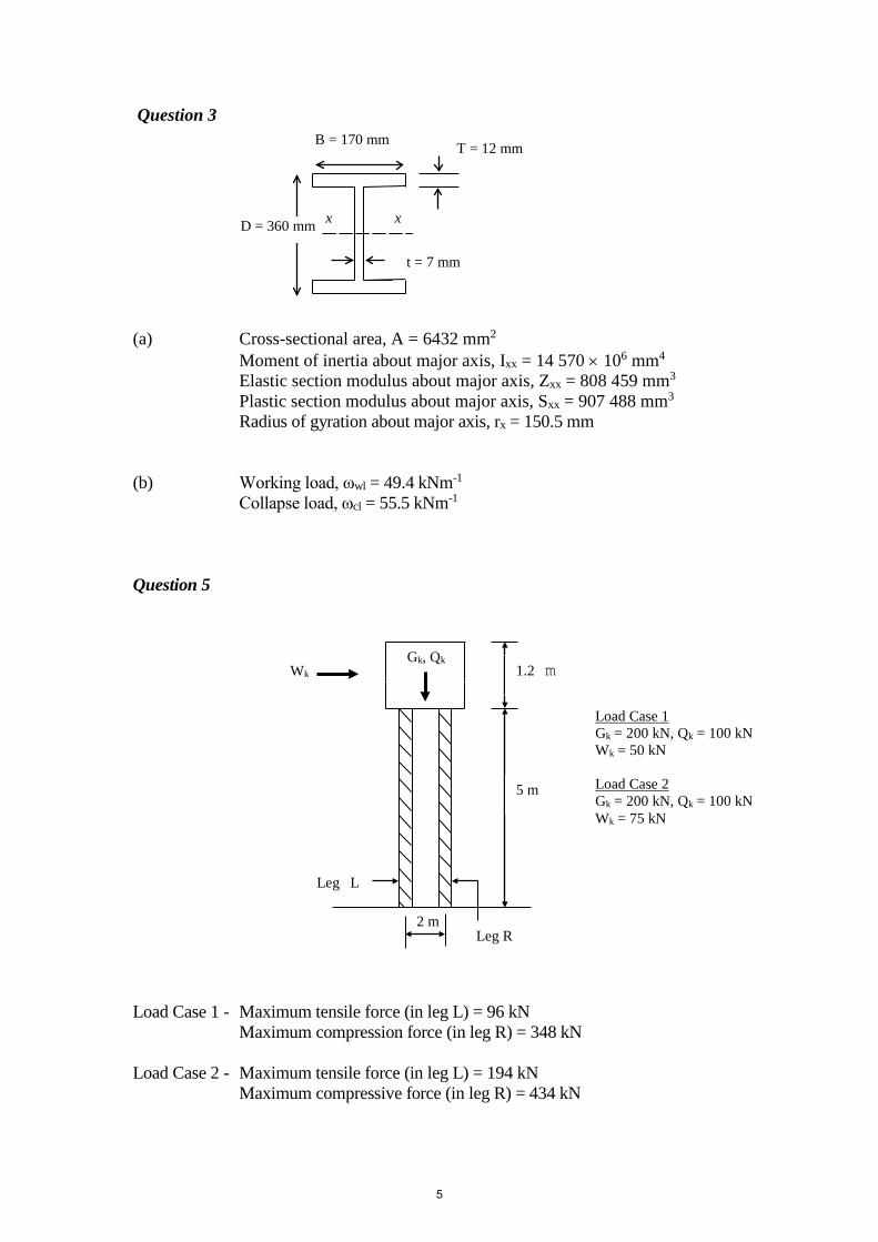
Question 3 (a) Cross-sectional area, A = 6432 mm2 Moment of inertia about major axis, Ixx = 14 570 × 106 mm4
Elastic section modulus about major axis, Zxx = 808 459 mm3 Plastic section modulus about major axis, Sxx = 907 488 mm3 Radius of gyration about major axis, rx = 150.5 mm
(b) Working load, ωwl = 49.4 kNm-1
Collapse load, ωcl = 55.5 kNm-1 Question 5 Load Case 1 - Maximum tensile force (in leg L) = 96 kN Maximum compression force (in leg R) = 348 kN Load Case 2 - Maximum tensile force (in leg L) = 194 kN Maximum compressive force (in leg R) = 434 kN
Wk
2 m
x
t = 7 mm
T = 12 mm
x
B = 170 mm
D = 360 mm
Gk, Qk 1.2 m
5 m
Leg L
Leg R
Load Case 1 Gk = 200 kN, Qk = 100 kN Wk = 50 kN Load Case 2 Gk = 200 kN, Qk = 100 kN Wk = 75 kN
5
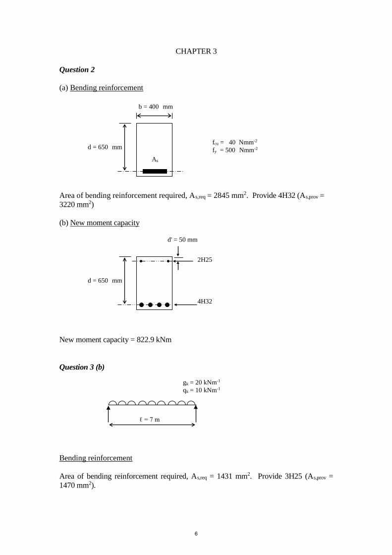
CHAPTER 3 Question 2 (a) Bending reinforcement Area of bending reinforcement required, As,req = 2845 mm2. Provide 4H32 (As,prov = 3220 mm2) (b) New moment capacity New moment capacity = 822.9 kNm Question 3 (b) Bending reinforcement Area of bending reinforcement required, As,req = 1431 mm2. Provide 3H25 (As,prov = 1470 mm2).
b = 400 mm
d = 650 mm fcu = 40 Nmm-2 fy = 500 Nmm-2
As
4H32
2H25
d' = 50 mm
gk = 20 kNm-1 qk = 10 kNm-1
ℓ = 7 m
d = 650 mm
6
Shear reinforcement
552.0=v
sv
sA
. Hence provide R10@275 (Asv/sv = 0.571)
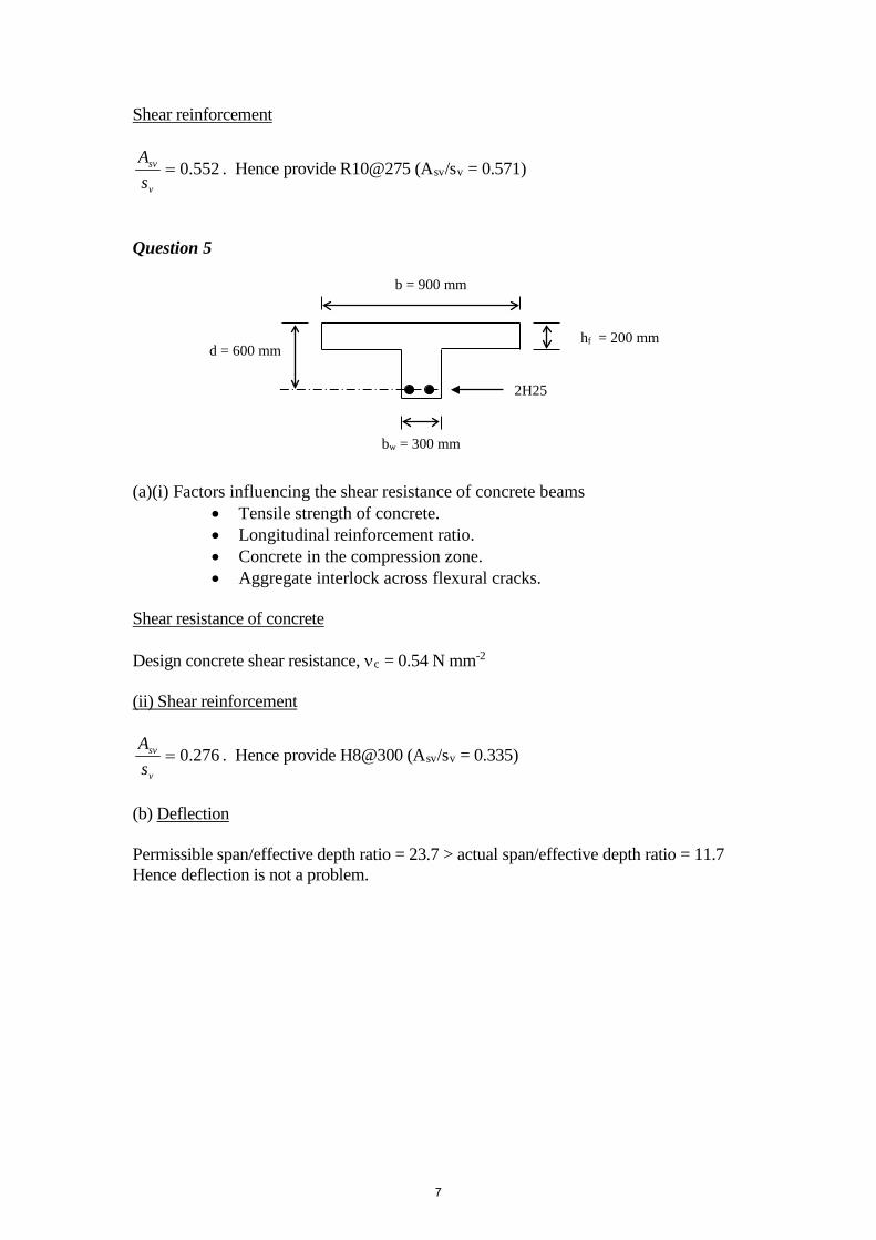
Question 5 (a)(i) Factors influencing the shear resistance of concrete beams
• Tensile strength of concrete. • Longitudinal reinforcement ratio. • Concrete in the compression zone. • Aggregate interlock across flexural cracks.
Shear resistance of concrete Design concrete shear resistance, νc = 0.54 N mm-2 (ii) Shear reinforcement
276.0=v
sv
sA
. Hence provide H8@300 (Asv/sv = 0.335)
(b) Deflection Permissible span/effective depth ratio = 23.7 > actual span/effective depth ratio = 11.7 Hence deflection is not a problem.
bw = 300 mm
d = 600 mm
b = 900 mm
hf = 200 mm
2H25
7
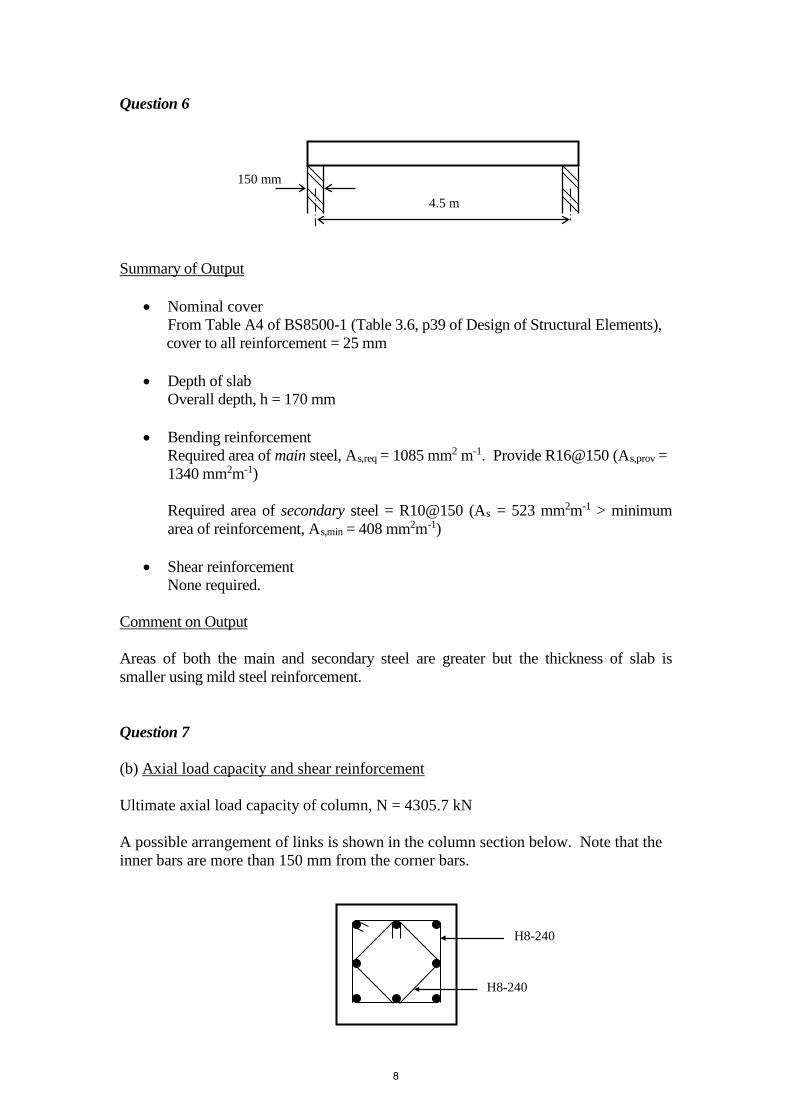
Question 6 Summary of Output
• Nominal cover From Table A4 of BS8500-1 (Table 3.6, p39 of Design of Structural Elements), cover to all reinforcement = 25 mm
• Depth of slab
Overall depth, h = 170 mm
• Bending reinforcement Required area of main steel, As,req = 1085 mm2 m-1. Provide R16@150 (As,prov = 1340 mm2m-1)
Required area of secondary steel = R10@150 (As = 523 mm2m-1 > minimum area of reinforcement, As,min = 408 mm2m-1)
• Shear reinforcement
None required. Comment on Output Areas of both the main and secondary steel are greater but the thickness of slab is smaller using mild steel reinforcement. Question 7 (b) Axial load capacity and shear reinforcement Ultimate axial load capacity of column, N = 4305.7 kN A possible arrangement of links is shown in the column section below. Note that the inner bars are more than 150 mm from the corner bars.
H8-240
H8-240
4.5 m
150 mm
8
Question 8 (a) Column classification ex ey
h b= = =
4500300
15
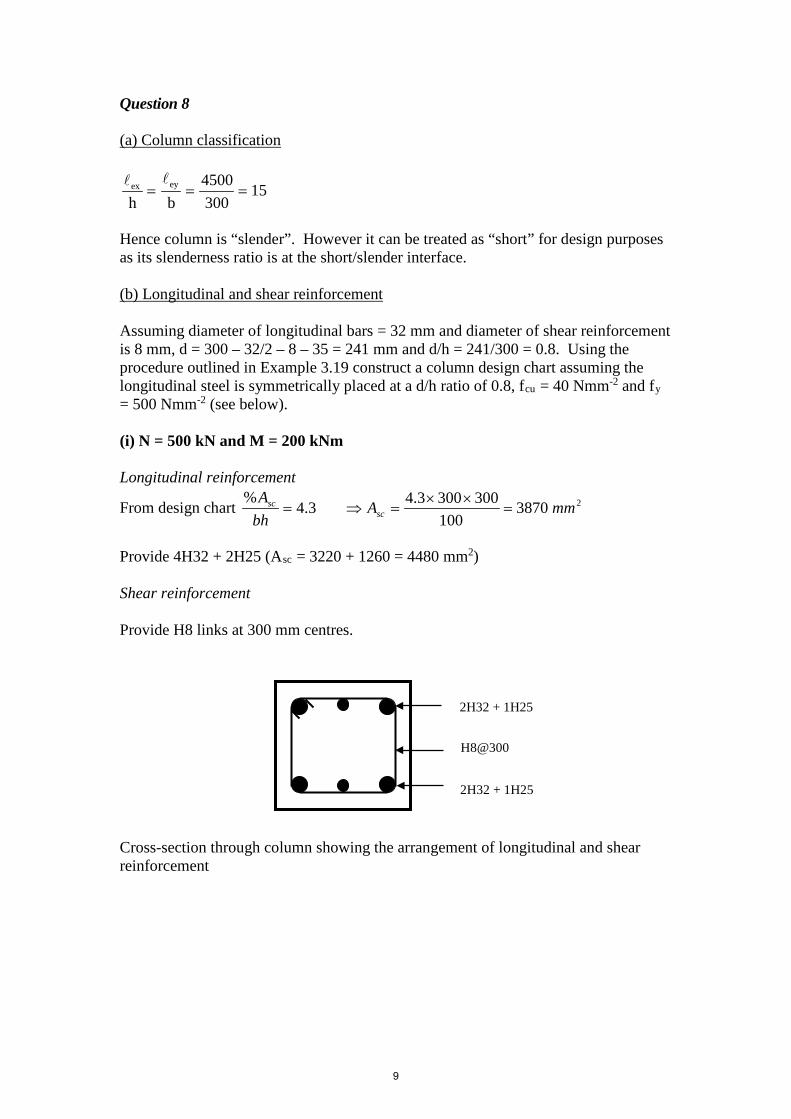
Hence column is “slender”. However it can be treated as “short” for design purposes as its slenderness ratio is at the short/slender interface. (b) Longitudinal and shear reinforcement Assuming diameter of longitudinal bars = 32 mm and diameter of shear reinforcement is 8 mm, d = 300 – 32/2 – 8 – 35 = 241 mm and d/h = 241/300 = 0.8. Using the procedure outlined in Example 3.19 construct a column design chart assuming the longitudinal steel is symmetrically placed at a d/h ratio of 0.8, fcu = 40 Nmm-2 and fy = 500 Nmm-2 (see below). (i) N = 500 kN and M = 200 kNm Longitudinal reinforcement
From design chart 23870100
3003003.43.4%
mmAbhA
scsc =
××=⇒=
Provide 4H32 + 2H25 (Asc = 3220 + 1260 = 4480 mm2) Shear reinforcement Provide H8 links at 300 mm centres. Cross-section through column showing the arrangement of longitudinal and shear reinforcement
2H32 + 1H25
H8@300
2H32 + 1H25
9
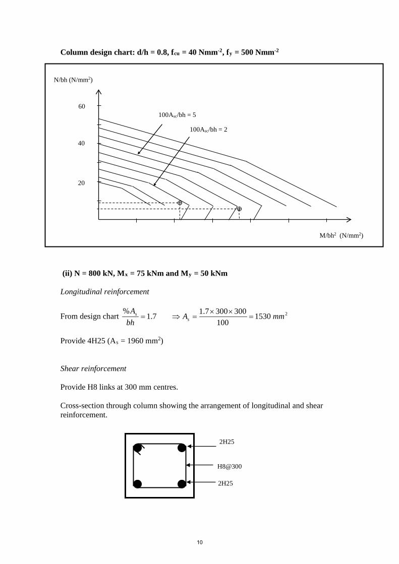
Column design chart: d/h = 0.8, fcu = 40 Nmm-2, fy = 500 Nmm-2 (ii) N = 800 kN, Mx = 75 kNm and My = 50 kNm Longitudinal reinforcement
From design chart 21530100
3003007.17.1%
mmAbhA
ss =
××=⇒=
Provide 4H25 (As = 1960 mm2) Shear reinforcement Provide H8 links at 300 mm centres. Cross-section through column showing the arrangement of longitudinal and shear reinforcement. 2H25 H8@300 2H25
100Asc/bh = 5
N/bh (N/mm2)
M/bh2 (N/mm2)
60
40
20
100Asc/bh = 2
10
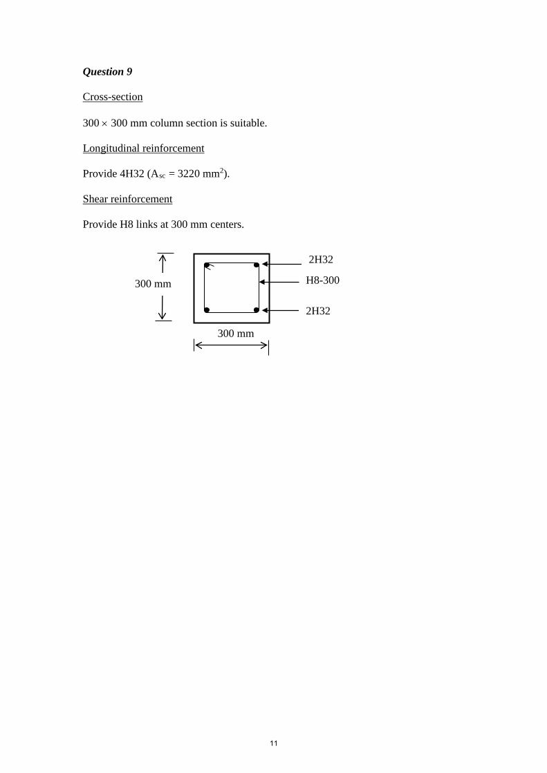
Question 9 Cross-section 300 × 300 mm column section is suitable. Longitudinal reinforcement Provide 4H32 (Asc = 3220 mm2). Shear reinforcement Provide H8 links at 300 mm centers.
300 mm
H8-300 300 mm
2H32
2H32
11
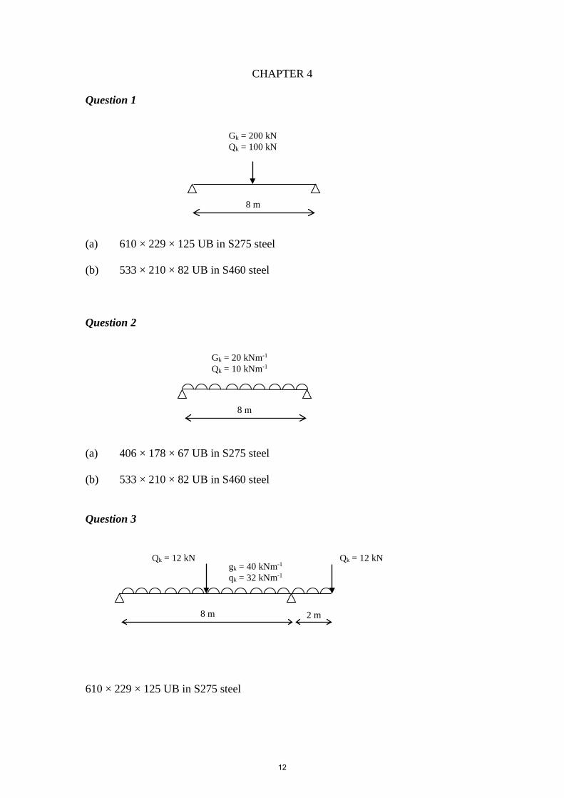
CHAPTER 4 Question 1 (a) 610 × 229 × 125 UB in S275 steel (b) 533 × 210 × 82 UB in S460 steel Question 2 (a) 406 × 178 × 67 UB in S275 steel (b) 533 × 210 × 82 UB in S460 steel Question 3 610 × 229 × 125 UB in S275 steel
Gk = 200 kN Qk = 100 kN
8 m
8 m
Gk = 20 kNm-1 Qk = 10 kNm-1
8 m 2 m
gk = 40 kNm-1 qk = 32 kNm-1
Qk = 12 kN Qk = 12 kN
12
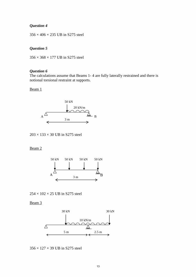
Question 4 356 × 406 × 235 UB in S275 steel Question 5 356 × 368 × 177 UB in S275 steel Question 6 The calculations assume that Beams 1- 4 are fully laterally restrained and there is notional torsional restraint at supports. Beam 1 203 × 133 × 30 UB in S275 steel Beam 2 254 × 102 × 25 UB in S275 steel Beam 3 356 × 127 × 39 UB in S275 steel
B A 3 m
20 kN/m
50 kN
B A 3 m
50 kN 50 kN 50 kN 50 kN
5 m 2.5 m
10 kN/m
30 kN 30 kN
13
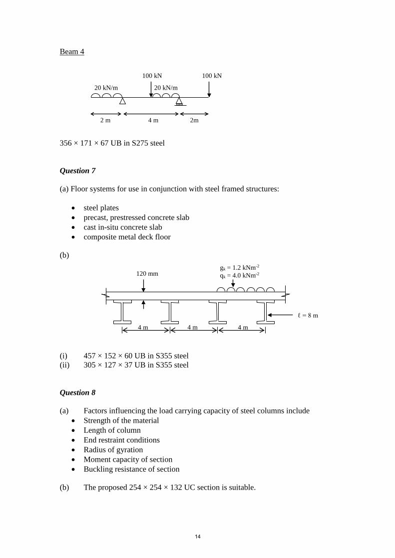
Beam 4 356 × 171 × 67 UB in S275 steel Question 7 (a) Floor systems for use in conjunction with steel framed structures:
• steel plates • precast, prestressed concrete slab • cast in-situ concrete slab • composite metal deck floor
(b) (i) 457 × 152 × 60 UB in S355 steel (ii) 305 × 127 × 37 UB in S355 steel Question 8 (a) Factors influencing the load carrying capacity of steel columns include
• Strength of the material • Length of column • End restraint conditions • Radius of gyration • Moment capacity of section • Buckling resistance of section
(b) The proposed 254 × 254 × 132 UC section is suitable.
4 m 4 m 4 m
2 m 4 m 2m
20 kN/m 20 kN/m
100 kN 100 kN
gk = 1.2 kNm-2 qk = 4.0 kNm-2 120 mm
ℓ = 8 m
14
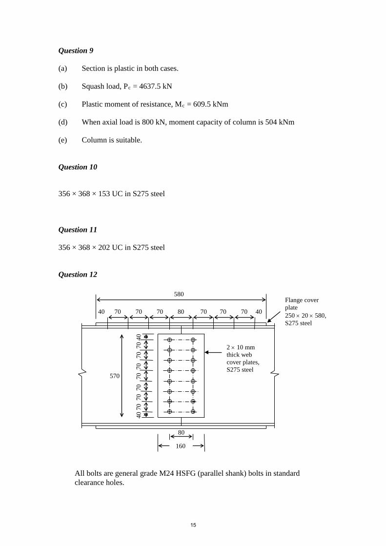
Question 9 (a) Section is plastic in both cases. (b) Squash load, Pc = 4637.5 kN (c) Plastic moment of resistance, Mc = 609.5 kNm (d) When axial load is 800 kN, moment capacity of column is 504 kNm (e) Column is suitable. Question 10 356 × 368 × 153 UC in S275 steel Question 11 356 × 368 × 202 UC in S275 steel Question 12
580
80
40 70 70 70 80 70 70 70 40
570
40
70 7
0 7
0 7
0 7
0 7
0 7
0 40
2 × 10 mm thick web cover plates, S275 steel
Flange cover plate 250 × 20 × 580, S275 steel
160
All bolts are general grade M24 HSFG (parallel shank) bolts in standard clearance holes.
15
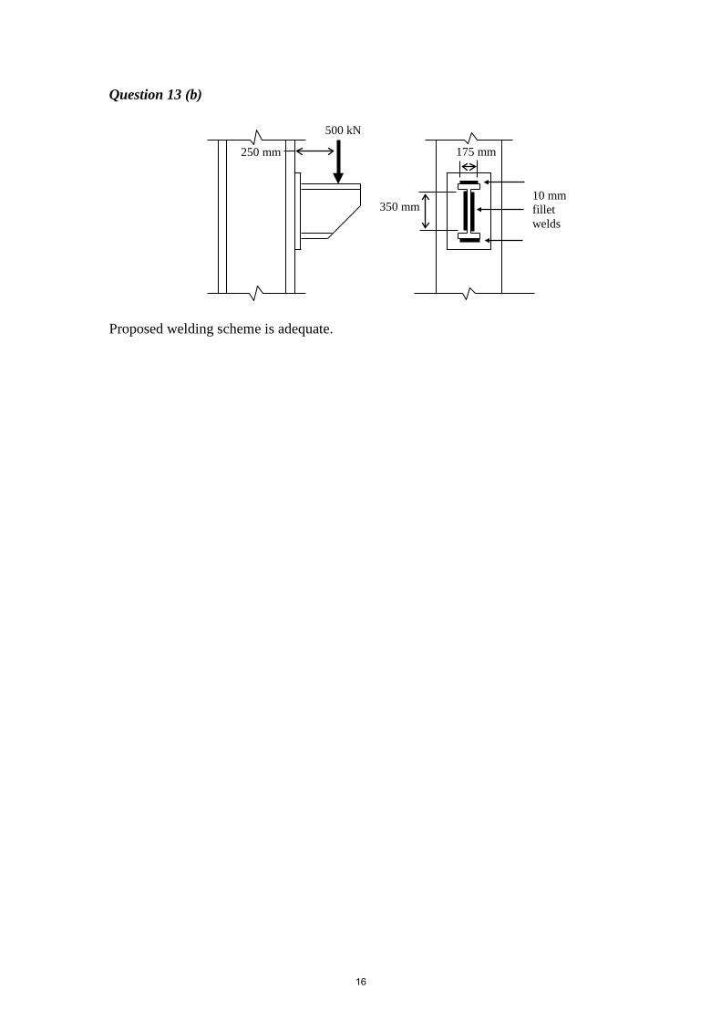
Question 13 (b) Proposed welding scheme is adequate.
10 mm fillet welds
175 mm
350 mm
500 kN
250 mm
16
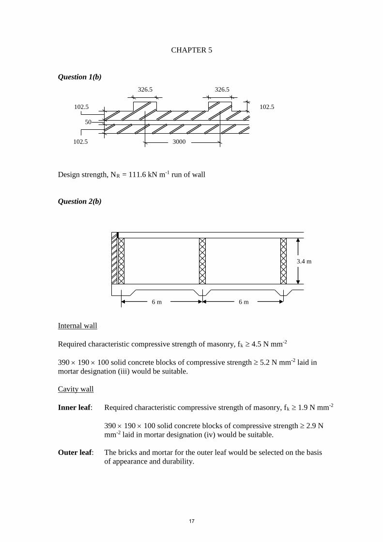
CHAPTER 5 Question 1(b) Design strength, NR = 111.6 kN m-1 run of wall Question 2(b) Internal wall Required characteristic compressive strength of masonry, fk ≥ 4.5 N mm-2 390 × 190 × 100 solid concrete blocks of compressive strength ≥ 5.2 N mm-2 laid in mortar designation (iii) would be suitable. Cavity wall Inner leaf: Required characteristic compressive strength of masonry, fk ≥ 1.9 N mm-2
390 × 190 × 100 solid concrete blocks of compressive strength ≥ 2.9 N mm-2 laid in mortar designation (iv) would be suitable.
Outer leaf: The bricks and mortar for the outer leaf would be selected on the basis
of appearance and durability.
50
102.5
102.5
326.5 326.5
102.5
3000
3.4 m
6 m 6 m
17
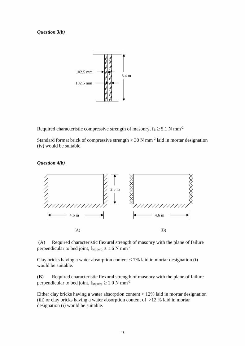
Question 3(b) Required characteristic compressive strength of masonry, fk ≥ 5.1 N mm-2 Standard format brick of compressive strength ≥ 30 N mm-2 laid in mortar designation (iv) would be suitable. Question 4(b) (A) Required characteristic flexural strength of masonry with the plane of failure perpendicular to bed joint, fkx perp ≥ 1.6 N mm-2 Clay bricks having a water absorption content < 7% laid in mortar designation (i) would be suitable. (B) Required characteristic flexural strength of masonry with the plane of failure perpendicular to bed joint, fkx perp ≥ 1.0 N mm-2 Either clay bricks having a water absorption content < 12% laid in mortar designation (iii) or clay bricks having a water absorption content of >12 % laid in mortar designation (i) would be suitable.
102.5 mm
102.5 mm
3.4 m
4.6 m 4.6 m
(A) (B)
2.5 m
18
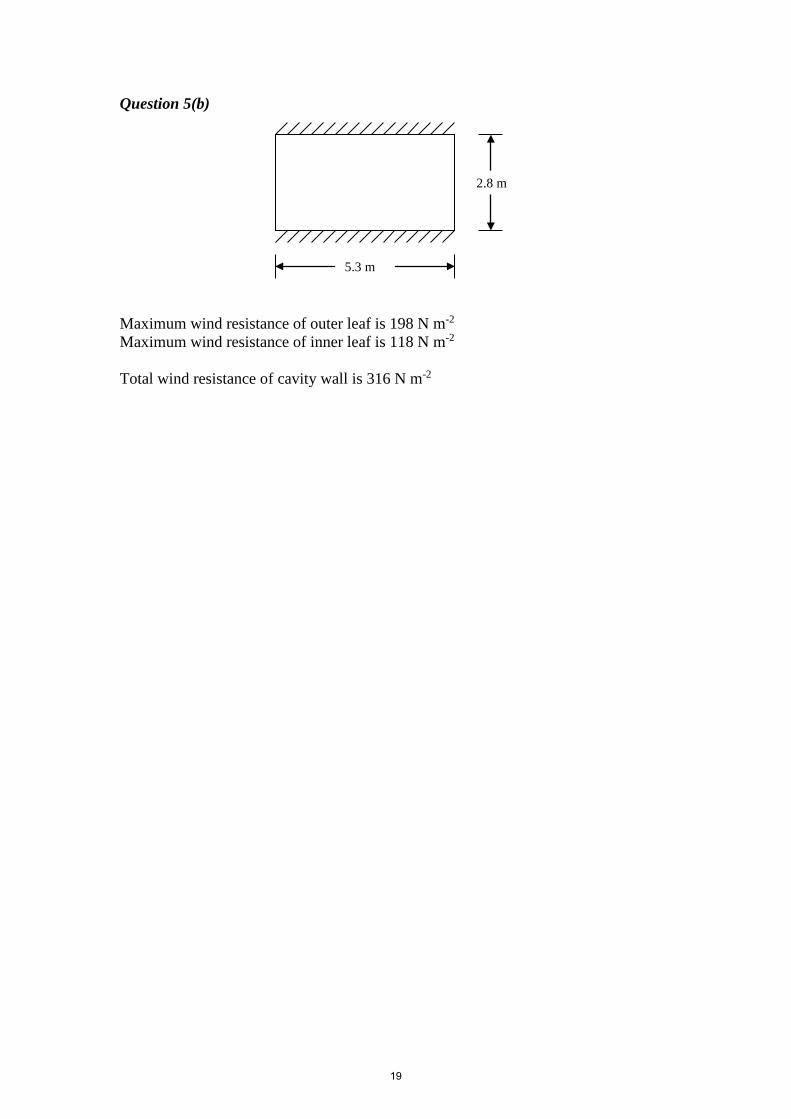
Question 5(b) Maximum wind resistance of outer leaf is 198 N m-2 Maximum wind resistance of inner leaf is 118 N m-2 Total wind resistance of cavity wall is 316 N m-2
5.3 m
2.8 m
19
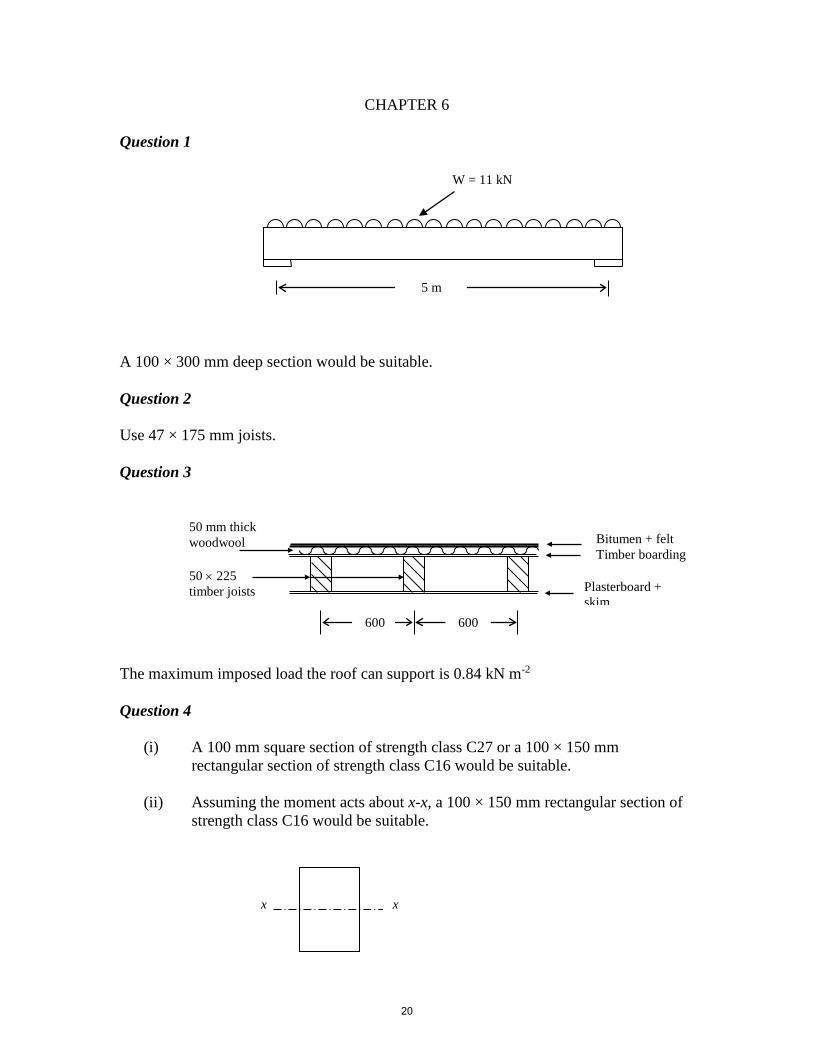
CHAPTER 6 Question 1 A 100 × 300 mm deep section would be suitable. Question 2 Use 47 × 175 mm joists. Question 3 The maximum imposed load the roof can support is 0.84 kN m-2 Question 4
(i) A 100 mm square section of strength class C27 or a 100 × 150 mm rectangular section of strength class C16 would be suitable.
(ii) Assuming the moment acts about x-x, a 100 × 150 mm rectangular section of
strength class C16 would be suitable.
W = 11 kN
5 m
x x
50 mm thick woodwool
50 × 225 timber joists
Bitumen + felt Timber boarding
600 600
Plasterboard + skim
20
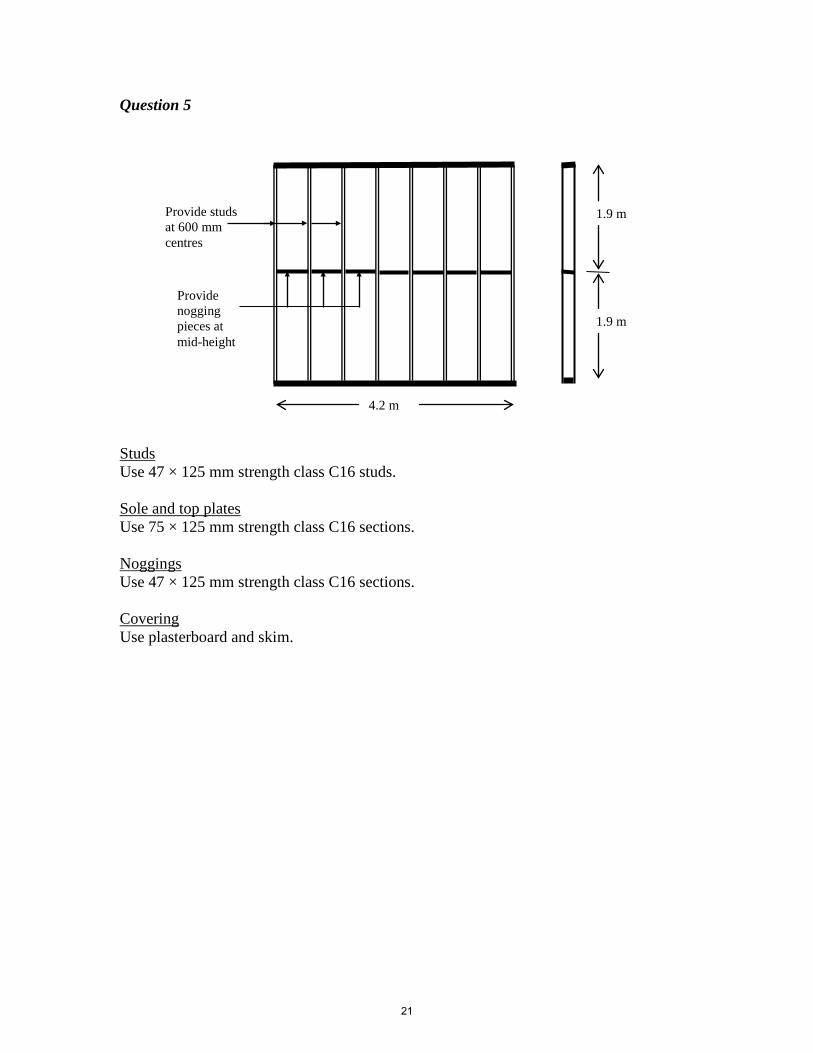
Question 5 Studs Use 47 × 125 mm strength class C16 studs. Sole and top plates Use 75 × 125 mm strength class C16 sections. Noggings Use 47 × 125 mm strength class C16 sections. Covering Use plasterboard and skim.
Provide nogging pieces at mid-height
Provide studs at 600 mm centres
4.2 m
1.9 m
1.9 m
21