structural design and performance of … · structural design and performance of composite...
TRANSCRIPT
STRUCTURAL DESIGN AND PERFORMANCE OF COMPOSITE
WALL-FOUNDATION CONNECTOR ELEMENTS
By
KRISTIN ANNE DUCHATEAU
A thesis submitted in partial fulfillment of the requirements for the degree of
MASTER OF SCIENCE IN CIVIL ENGINEERING
WASHINGTON STATE UNIVERSITY Department of Civil and Environmental Engineering
AUGUST 2005
ii
To the Faculty of Washington State University:
The members of the Committee appointed to examine the thesis of KRISTIN ANNE
DUCHATEAU find it satisfactory and recommend that it be accepted.
Co-Chair
Co-Chair

iii
ACKNOWLEDGMENT
I would like to thank the many people who provided assistance and support throughout
this project. A few groups need to be formally recognized:
• Committee members, Dr. J. Daniel Dolan, Dr. Michael Wolcott, and Dr. David
Pollock, for their guidance and engineering insight,
• Office of Naval Research (under contract N00014-03-1-0949) for providing the
funding to perform this research,
• Wood Materials & Engineering Lab and Department of Civil & Environmental
Engineering faculty and staff for laboratory, technical, and administrative
assistance, and
• Family, friends, and fellow grad students for their conversation and
encouragement along the way.
iv
STRUCTURAL DESIGN AND PERFORMANCE OF COMPOSITE WALL-FOUNDATION
CONNECTOR ELEMENTS
Abstract
by Kristin Anne Duchateau, M.S. Washington State University
August 2005
Co-Chairs: J. Daniel Dolan & Michael P. Wolcott
Field observations following extreme earthquake events and laboratory testing identify a
key area to improve upon in wood-frame shear walls as maintaining sill plate structural integrity.
Due to current load paths through the sill plate when resisting overturning, coupled by
construction misalignments, traditional sill plate designs split along the line of anchor bolts and
lose lateral resistance. In addition, this location in a structure is susceptible to moisture
infiltration. Therefore, structural member degradation from moisture and the required use of
potentially hazardous preservative treatments makes it advantageous to develop durable wood
thermoplastic composites (WPCs) as structural members for this location.
This paper presents an experimental investigation and proof of concept of the utilization
of WPC members as sill plates in wood shear walls. Connection and component testing of one
polypropylene hollow section (PP10) identified weakness in the perpendicular-to-extrusion
direction, though with the use of reinforcement, performance was improved. Final design
configurations showed an improvement of 27-31 kN (6000-7000 lbf) in uplift resistance over
traditional end stud-to-sill connections without hold-down hardware. As well, improvements in
section design have eliminated rotation and cross-grain bending in sills (forces that have caused
brittle splitting of wood sills).
v
Full scale shear wall tests were performed on one wood sill wall configuration (as the
control) and three wall configurations with WPC sills, none of the four configurations used
conventional hold-down hardware. Changes in capacities, ductility, and energy dissipation
resulted from different sill plate materials and configurations. Cyclic response exceeded
monotonic response for walls with WPC sill plates. One WPC section was shown to be a
feasible equal substitution to wood sill plates, obtaining similar performance parameters.
Another WPC sill plate wall configuration had substantial improvements in capacities and
exhibited racking behavior and associated failure modes, developing a completely different load-
deformation response. Stiffness degradation for this section was the most gradual, allowing
more than a two-fold increase in energy dissipation and retention of its ability to resist
deformations in a plastic state.

vi
TABLE OF CONTENTS
ACKNOWLEDGMENT............................................................................................................... III
ABSTRACT.................................................................................................................................. IV
TABLE OF CONTENTS.............................................................................................................. VI
LIST OF TABLES..........................................................................................................................X
LIST OF FIGURES .....................................................................................................................XII
CHAPTER 1 INTRODUCTION .....................................................................................................1
1.1 Problem Overview .................................................................................................................1
1.2 Design Modifications.............................................................................................................4
1.2.1 Code Development............................................................................................ 4
1.2.2 Experimental Results ........................................................................................ 5
1.3 Motivation.............................................................................................................................8
1.4 Objectives ...........................................................................................................................10
CHAPTER 2 MATERIALS AND METHODS ............................................................................11
2.1 Sill Plate Materials...............................................................................................................11
2.2 Design Methodology............................................................................................................14
2.3 Connection Test Materials and Methods .............................................................................17
2.4 Component Test Materials and Methods .............................................................................22
2.5 Shear Wall Test Materials and Methods..............................................................................25
2.5.1 Sill Plate Type.................................................................................................. 26
2.5.2 Fabrication of Specimens................................................................................. 26
2.5.3 Test Fixtures and Instrumentation ................................................................... 29
vii
2.5.4 Test Procedure ................................................................................................. 31
CHAPTER 3 CONNECTION AND COMPONENT PERFORMANCE .....................................34
3.1 Connection Tests..................................................................................................................34
3.1.1 Effect of Varying Sidewall Connection Geometry.......................................... 34
3.1.2 Effect of Configuration Changes ..................................................................... 37
3.1.3 Effect of Reinforcement Methods.................................................................... 38
3.1.3.1 Traditional Configuration ......................................................................... 39
3.1.3.2 Shifted Configuration................................................................................ 40
3.1.4 Finalized End Stud/Sill Connection................................................................. 42
3.2 Component Tests .................................................................................................................43
3.3 Connection and Component Test Summary ........................................................................47
CHAPTER 4 SHEAR WALL PERFORMANCE .........................................................................48
4.1 Test Parameters....................................................................................................................48
4.2 Monotonic Test Results .......................................................................................................51
4.1.1 Test WOOD4-M .............................................................................................. 52
4.2.2 Test PE3-M ...................................................................................................... 55
4.2.3 Test PP5-M ...................................................................................................... 57
4.2.4 Test PP10-M .................................................................................................... 60
4.3 Monotonic Test Conclusions ...............................................................................................63
4.4 Cyclic Test Results ..............................................................................................................68
4.4.1 WOOD4 ........................................................................................................... 68
4.4.2 PE3................................................................................................................... 70
4.4.3 PP5 ................................................................................................................... 72
viii
4.4.4 PP10 ................................................................................................................. 74
4.5 Cyclic Test Discussion.........................................................................................................77
4.5.1 Test Group Comparison................................................................................... 77
4.5.2 Shear Deformation Contributions .................................................................... 79
4.5.3 Earthquake Performance Evaluation of PP10.................................................. 80
4.5.4 Comparison of Monotonic and Cyclic Results ................................................ 83
4.5.5 Cyclic Stiffness ................................................................................................ 84
4.5.6 Cyclic Test Results .......................................................................................... 87
CHAPTER 5 CONCLUSIONS AND RECOMMENDATIONS..................................................89
5.1 Connection and Component Conclusions............................................................................89
5.2 Shear Wall Conclusions.......................................................................................................90
5.3 Future Research ...................................................................................................................92
REFERENCES ..............................................................................................................................95
APPENDIX A: CONNECTION AND COMPONENT TEST RESULTS ...................................99
A.1 Connection Test Fastener Configurations...........................................................................99
A.2 Connection Test Failure Photos ........................................................................................102
A.3 Connection Test Detailed Test Data .................................................................................104
A.4 Component Test Detailed Test Data .................................................................................105
APPENDIX B: SHEAR WALL TEST RESULTS ....................................................................106
B.1 Test Setup..........................................................................................................................106
B.2 Supplement Test Photos: Test PP10-M Failures...............................................................107
B.3 Cyclic Test Data ................................................................................................................110
ix
Test WOOD4-1....................................................................................................... 111
Test WOOD4-2....................................................................................................... 114
Test PE3-1............................................................................................................... 117
Test PE3-2............................................................................................................... 120
Test PP5-2............................................................................................................... 126
Test PP10-1............................................................................................................. 129
Test PP10-2............................................................................................................. 132
B.4 Cyclic Stiffness .................................................................................................................135
B.5 Load Washer .....................................................................................................................136
Monotonic Results .................................................................................................. 137
Cyclic Results ......................................................................................................... 141
x
LIST OF TABLES
Table 2.1 Sill plate member properties ......................................................................................12
Table 2.2 Extruder temperature profile......................................................................................13
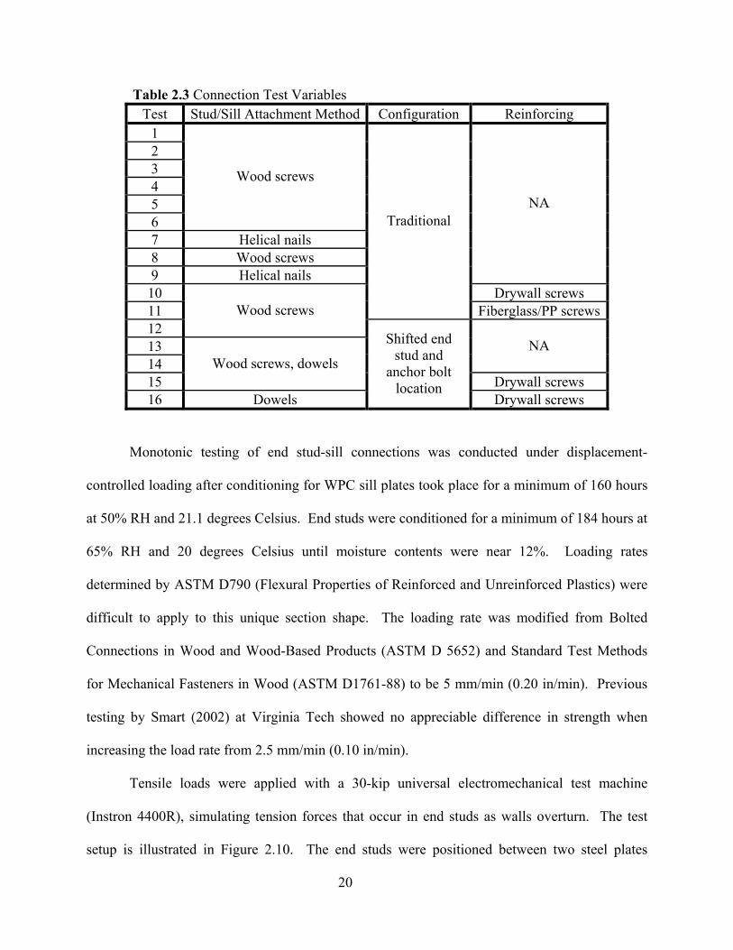
Table 2.3 Connection Test Variables.........................................................................................20
Table 2.4 Shear wall configurations .........................................................................................26
Table 2.5 Framing and sheathing heights for tests ....................................................................27
Table 2.6 Nail specifications......................................................................................................28
Table 2.7 Cyclic wall test reference displacements ...................................................................31
Table 2.8 CUREE Protocol: Amplitudes of primary cycles (Krawinkler, 2001) ......................32
Table 3.1 Connection Test Summary.........................................................................................34
Table 3.2. Comparison of stiffness values for connection tests and previous monotonic
shear wall tests (2.44 m) (8 feet)........................................................................................46
Table 4.1 Monotonic test summary of performance parameters ...............................................64
Table 4.2 Comparison of monotonic test parameters ................................................................65
Table 4.3 Performance parameters ............................................................................................68
Table 4.4 Amount of wall displacement from shear deformations at point of maximum
load.....................................................................................................................................79
Table 4.5 Capacities of walls with overturning anchorage........................................................81
Table 4.6 Comparison of monotonic and cyclic wall capacities ...............................................84
Table A.1 Full connection test data ........................................................................................104
Table A.2 Full component test data ........................................................................................105
Table B.l Test WOOD4-1 Summary .......................................................................................111
Table B.2 Test WOOD4-1 Energy and damping data .............................................................113
xi
Table B.3 Test WOOD4-2 Summary.......................................................................................114
Table B.4 Test WOOD4-2 Energy and damping data .............................................................116
Table B.5 Test PE3-1 Summary ..............................................................................................117
Table B.6 Test PE3-1 Energy and damping data.....................................................................119
Table B.7 Test PE3-2 Summary ..............................................................................................120
Table B.8 Test PE3-2 Energy and damping data.....................................................................122
Table B.9 Test PP5-1 Summary...............................................................................................123
Table B.10 Test PP5-1 Energy and damping data ...................................................................125
Table B.11 Test PP5-2 Summary.............................................................................................126
Table B.12 Test PP5-2 Energy and damping data ...................................................................128
Table B.13 Test PP10-1 Summary...........................................................................................129
Table B.14 Test PP10-1 Energy and damping data .................................................................131
Table B.15 Test PP10-2 Summary...........................................................................................132
Table B.16 Test PP10-2 Energy and damping data .................................................................134
Table B.17 Cyclic stiffness values...........................................................................................135
xii
LIST OF FIGURES
Figure 2.1 Section profiles utilized for sill plates: (a) WOOD4: Pressure treated wood sill,
(b) PE3: Solid polyethylene, (c) PP5: Hollow polypropylene three-box, and (d)
PP10: Hollow polypropylene.............................................................................................11
Figure 2.2 Conceptual sill plate system ....................................................................................15
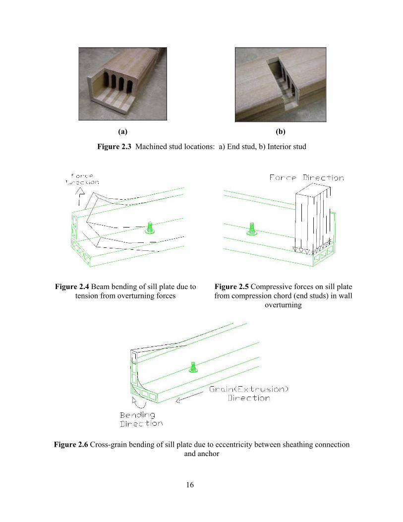
Figure 2.3 Machined stud locations: a) End stud, b) Interior stud...........................................16
Figure 2.4 Beam bending of sill plate due to tension from overturning forces .........................16
Figure 2.5 Compressive forces on sill plate from compression chord (end studs) in wall
overturning.........................................................................................................................16
Figure 2.6 Cross-grain bending of sill plate due to eccentricity between sheathing
connection and anchor .......................................................................................................16
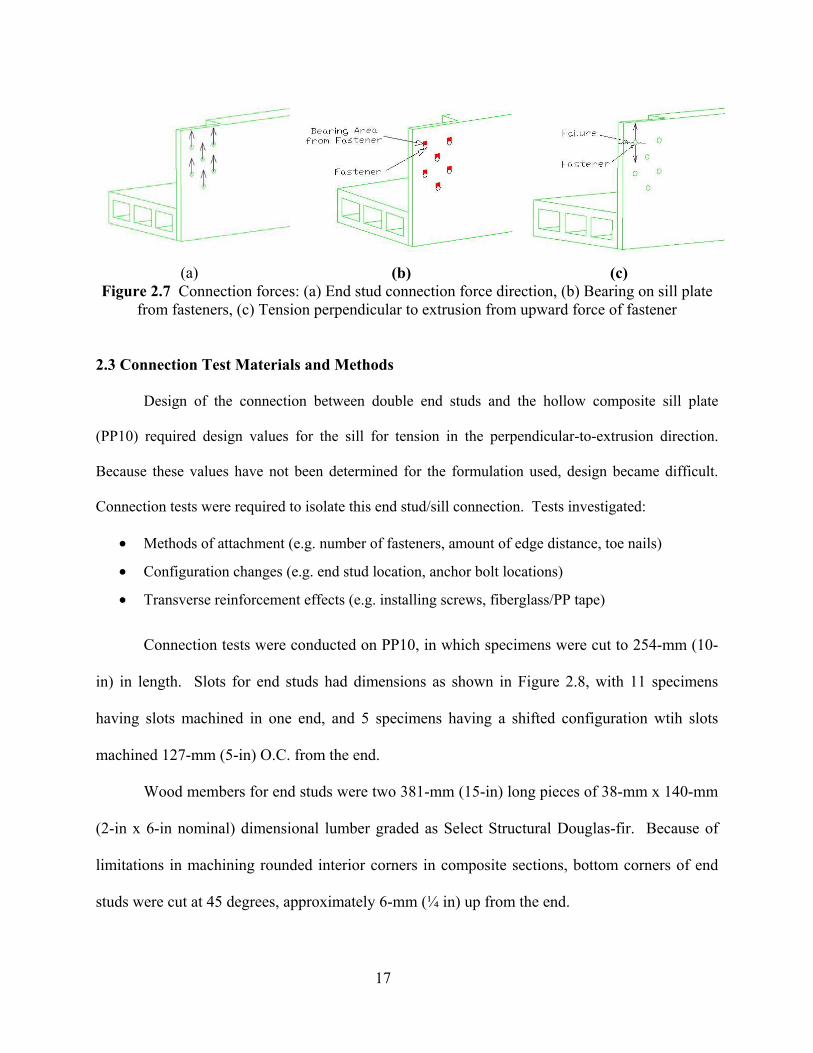
Figure 2.7 Connection forces: (a) End stud connection force direction, (b) Bearing on sill
plate from fasteners, (c) Tension perpendicular to extrusion from upward force of
fastener...............................................................................................................................17
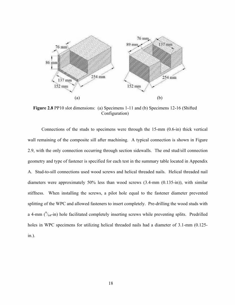
Figure 2.8 PP10 slot dimensions: (a) Specimens 1-11 and (b) Specimens 12-16 (Shifted
Configuration)....................................................................................................................18
Figure 2.9 Typical connection test geometry............................................................................19
Figure 2.10 Connection test setup.............................................................................................21
Figure 2.11 Component design: a) Full section, b) End stud detail.........................................23
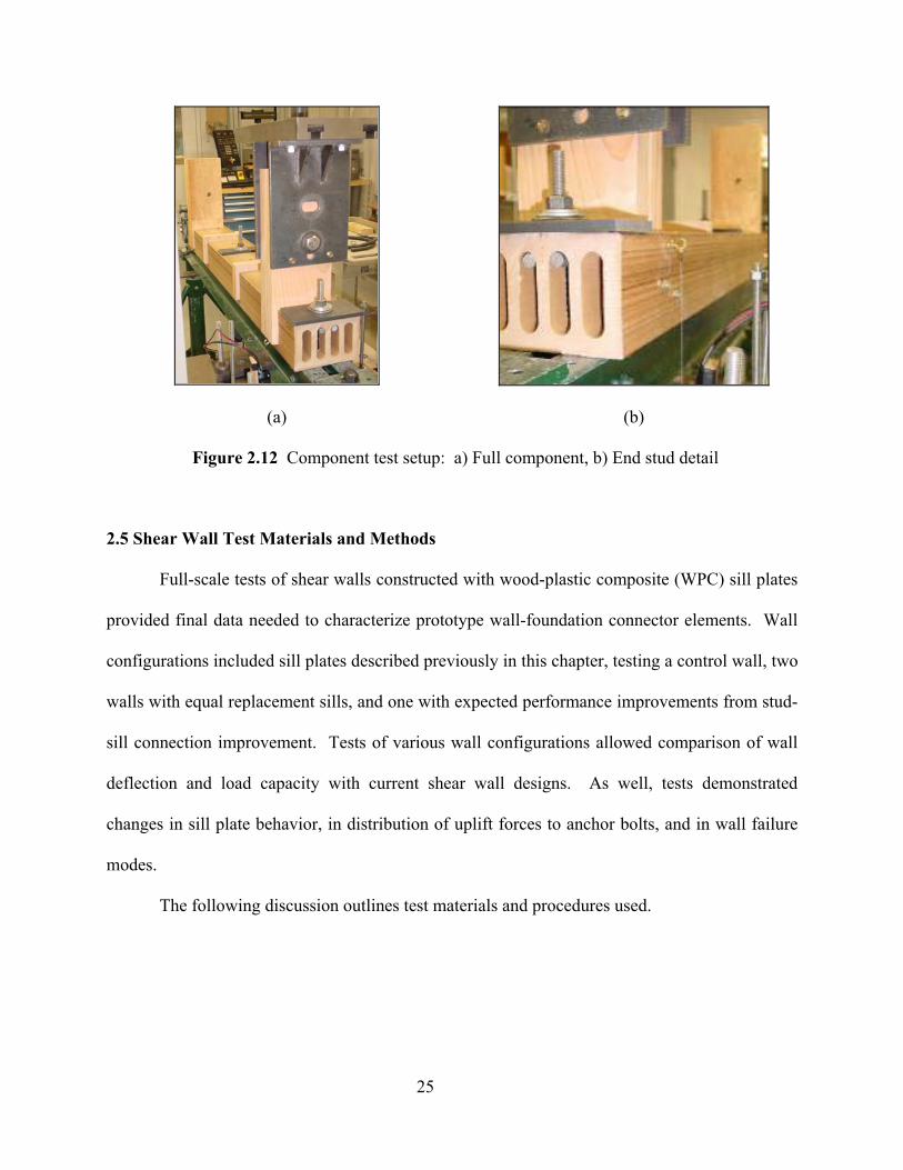
Figure 2.12 Component test setup: a) Full component, b) End stud detail..............................25
Figure 2.13 PP10 stud configuration (end view) .......................................................................27
Figure 2.14 Shear wall test frame ..............................................................................................30
Figure 2.15 Shear wall test instrumentation ..............................................................................30
xiii
Figure 2.16 CUREE loading protocol........................................................................................32
Figure 3.1 Typical failure path in connection tests (Specimen 4 shown).................................35
Figure 3.2 Failure perpendicular-to-extrusion between flange and webs from uplift force
transferred to dowels..........................................................................................................38
Figure 3.3 Comparison of load-deflection behavior from moving end stud position and
adding dowels ....................................................................................................................38
Figure 3.4 Reinforced sill failure photo (Specimen 10) ............................................................39
Figure 3.5 Effects of reinforcing sidewall connection...............................................................40
Figure 3.6 Perpendicular-to-extrusion screw reinforcement between flange and webs ............41
Figure 3.7 Effects of reinforcing top flange to web...................................................................41
Figure 3.8 Beam bending in component tests from dowel uplift...............................................44
Figure 3.9 Typical component test flexural failure at end stud slot...........................................44
Figure 3.10 Component test load deflection curves: a) Performance parameters and spread
of data, b) Structural stiffness calculation..........................................................................45
Figure 4.1 Response curve of monotonic wall test with traditional pressure-treated sill
plate (WOOD4-M).............................................................................................................52
Figure 4.2 Monotonic test failures in sill: (a) Sill plate splitting along edge of plate washer
and studs unzipping on loaded end of wall, (b) Split sill plate (end view)........................53
Figure 4.3 Load washer placement for WOOD4, PE3, and PP5 ...............................................54
Figure 4.4 Test WOOD4-M Load washer readings over time...................................................54
Figure 4.5 Response curve of monotonic wall test with solid polyethylene sill plate (PE3-
M).......................................................................................................................................55
xiv
Figure 4.6 Sill failures: (a) Sill bending and flexural cracking at anchor bolt nearest loaded
end stud, and (b) Plate washer indentation and anchor bolt hole size increase from
bearing................................................................................................................................56
Figure 4.7 Nail bending and tear-out from sheathing and sill plate at loaded end of wall ........56
Figure 4.8 Test PE3-M Load washer readings over time ..........................................................57
Figure 4.9 Response curve of monotonic wall test with hollow polypropylene three-box
sill plate (PP5-M)...............................................................................................................58
Figure 4.10 View of sill bending and splitting: (a) Overall behavior of sill end, (b) View
from top of split along strand.............................................................................................59
Figure 4.11 View of failure at anchor bolt location, shown from outside bottom edge ............59
Figure 4.12 Test PP5-M Load washer readings over time.........................................................60
Figure 4.13 Response curve of monotonic wall test with polypropylene 100 mm x 152 mm
hollow sill plate (PP10)......................................................................................................61
Figure 4.14 Overall PP10 hollow sill plate behavior (load being applied from right side)......62
Figure 4.15 Sill failure at end stud: (a) First flexural failure, (b) Failure through section
and dowels crushing upper flange and yielding.................................................................62
Figure 4.16 Test PP10-M Load washer readings over time.......................................................63
Figure 4.17 Load-displacement curves for monotonic tests .....................................................64
Figure 4.18 EEEP curves from monotonic test results ..............................................................65
Figure 4.19 Racking displacement of walls in monotonic tests.................................................66
Figure 4.20 WOOD4 response curves .......................................................................................69
xv
Figure 4.21 WOOD4 failures: (a) Typical sill splitting full length (Test WOOD4-1), (b)
Sill end split (Test WOOD4-2), and (c) Sheathing nail pull-out at wall end (Test
WOOD4-1) ........................................................................................................................70
Figure 4.22 PE3 response curves ...............................................................................................71
Figure 4.23 PE3 failures: (a) Overall bending during test (Test PE3-2), (b) Failures near
end anchor bolt (Test PE3-1), and (c) End anchor bolt plate washer indentation and
45 degree failure (Test PE3-1)...........................................................................................72
Figure 4.24 PP5 response curves ...............................................................................................73
Figure 4.25 PP5 failures: (a) Side box split down length of sill, (b) Bottom view of split
box between outside web and flange and flexural failure, and (c) End view of split
showing separation between strands..................................................................................74
Figure 4.26 PP10 response curves .............................................................................................75
Figure 4.27 PP10 failures: (a) Flexural failure at interior anchor bolt, (b) Flexural failure
at end stud connection, (c) End view of dowels yielding , (d) Yielded dowels from
Test PP10-2, (e) Failure plane along section strands, and (f) Nail pull-through at panel
joint (inset photos of yielded fasteners and view of panel joint from outside)..................76
Figure 4.28 Best fit lines for each test group .............................................................................77
Figure 4.29 Average EEEP curves for wall configurations under monotonic and cyclic
loading................................................................................................................................82
Figure 4.30 Stiffness degradation from cyclic loading..............................................................86
Figure A.1 Connection configurations.....................................................................................100
Figure A.2 Connection Tests 1-12 failure photos....................................................................102
Figure A.3 Connection Tests 13-16 failure photos..................................................................103
xvi
Figure B.1 Shear wall test setup photos...................................................................................106
Figure B.2 Test PP10-M sill failure and overall behavior ......................................................107
Figure B.3 Interior stud-to-sill connection behavior: (a) Nail bending with sheathing
racking, (b) Stud splitting from screw connectors, and (c) Interior stud movement in
slot and crack in bottom flange........................................................................................107
Figure B.4 Illustration of sheathing racking: (a) Bearing on sill top, (b) Displacing 13-19
mm (0.5-0.75 inches) past end of sill, and (c) Racking at panel joint .............................108
Figure B.5 End stud failed connection (top view): dowels yielded, top flange crushed, sill
cracked through................................................................................................................109
Figure B.6 Flexural failure at second anchor bolt: (a) Location along sill, (b) Failure
exposes anchor bolt within...............................................................................................109
Figure B.7 Test WOOD4-1 Hysteresis: Reference Displacement = 41 mm (1.61 in).............112
Figure B.8 Time history for Test WOOD4-1...........................................................................112
Figure B.9 Test WOOD4-2 Hyteresis: Reference Displacement = 41 mm (1.61 in) ..............115
Figure B.10 Time history for Test WOOD4-2.........................................................................115
Figure B.11 Test PE3-1 Hysteresis: Reference Displacement = 36 mm (1.40 in) ..................118
Figure B.12 Time history for Test PE3-1 ................................................................................118
Figure B.13 Test PE3-2 Hysteresis: Reference Displacement = 36 mm (1.40 in) ..................121
Figure B.14 Time history for Test PE3-2 ................................................................................121
Figure B.15 Test PP5-1 Hysteresis (Reference Displacement = 18 mm (0.70 in)) .................124
Figure B.16 Time history for Test PP5-1 ................................................................................124
Figure B.17 Test PP5-2 Hysteresis (Reference Displacement = 18 mm (0.70 in)) .................127
Figure B.18 Time history for Test PP5-2 ................................................................................127
xvii
Figure B.19 Test PP10-1 Hysteresis (Reference Displacement = 35 mm (1.39 in)) ...............130
Figure B.20 Time history for Test PP10-1 ..............................................................................130
Figure B.21 Test PP10-2 Hysteresis (Reference Displacement = 35 mm (1.39 in)) ...............133
Figure B.22 Time history for Test PP10-2 ..............................................................................133
Figure B.25 Test WOOD4-M load washer data ......................................................................137
Figure B.26 Test PE3-M load washer data ..............................................................................137
Figure B.27 Test PP5-M load washer data ..............................................................................138
Figure B.28 Test PP10-M load washer data ............................................................................138
Figure B.29 Load washer 1 test data........................................................................................139
Figure B.30 Load washer 2 test data........................................................................................139
Figure B.31 Load washer 3 test data........................................................................................140
Figure B.32 Test WOOD4-1 load washer time history ...........................................................141
Figure B.33 Test WOOD4-2 load washer time history ...........................................................141
Figure B.34 Test PE3-1 load washer time history ...................................................................142
Figure B.35 Test PE3-2 load washer time history ...................................................................142
Figure B.36 Test PP5-1 load washer time history ...................................................................143
Figure B.37 Test PP5-2 load washer time history ...................................................................143
Figure B.38 Test PP10-1 load washer time history .................................................................144
Figure B.39 Test PP10-2 load washer time history .................................................................144
1
CHAPTER 1 INTRODUCTION
To improve upon lateral load resistance and durability of wood building envelopes,
research is currently being conducted on “Durable Wood Composites for Naval Low-Rise
Buildings” at Washington State University. This work is funded by the U.S. Navy’s Office of
Naval Research. The U.S. Navy has considerable inventory in low-rise timber construction.
The coastal location of these buildings results in significant exposure to moisture, causing large
maintenance problems and potentially high costs for ownership. Additionally, these facilities are
often located in areas of high seismic or hurricane risk, requiring an increased level of structural
performance. The need for durable materials used in engineered applications provides the
opportunity to research wood thermoplastic composites utilized as structural members.
This study investigates the application of wood plastic composites (WPCs) in wall-to-
foundation connections of wood-frame buildings. A literature review will identify current
structural problems in lateral force systems, outline design requirements, present previous
experimental results, and establish advantages of utilizing WPC material. Following the
literature review, the objectives and scope of this research will identify necessary experimental
investigations in designing a prototype wood-to-foundation connection system.
1.1 Problem Overview
Wood-frame buildings were perceived to perform relatively well in earthquake loadings
due to their highly redundant structural systems. Northridge earthquake in 1994 contradicted this
perception and shifted attention in the structural community towards improving seismic
performance of these buildings. Wood-frame building failures accounted for $20 billion in
property loss, outweighing losses incurred by any other single type of building construction.
2
This damage resulted in 100,000 residents temporarily displaced, and an additional 50,000
residents unable to return to their homes. Numerous injuries, and 24 out of 25 fatalities
occurring in the Northridge earthquake, were attributable to failures in wood-frame buildings
(Mahaney and Kehoe, 2002). These losses contributed to the most costly natural disaster in
United States history (Moehle, 1994).
Wood-frame construction comprises a substantial portion of building inventory in the
United States—80-90% of all structures. In Los Angeles County alone, wood-frame
construction accounts for 81% of total structures and 99% of residences. (Mahaney and Kehoe,
2002). With such a large percentage of the nation’s population occupying wood-frame
structures, the consequences of the Northridge earthquake present widespread concern.
Shear wall and lateral force resisting systems were particularly prone to failure during the
Northridge earthquake, contributing to 167 dwellings being demolished (Schierle, 2002). Field
observations found signs of failure including exterior cracking at sill-foundation connections,
significant deformation at wall boundaries, sliding of walls along foundations, and splitting of
sill plates (Day, 1996). Cases of limited shear resistance result from hold-down connections
stretching where shear and overturning forces concentrate, from bolt holes being spaced too
close or too far apart, having over-drilled bolt holes, or inadequate number of anchors. Resulting
slip and deformation reduce lateral force capacity after sill plates split longitudinally
(Hamburger, 1994). The concealed nature of these structural failures makes damage difficult to
identify and costly to repair after a large loading event (Schierle, 2002). Immediately, damages
in walls at the base of structures may have detrimental effects on the remaining structure—
causing further deformations, or even collapse.
3
Improper installation methods were identified as a factor in poor sill plate behavior when
subjected to high stresses. Misalignments in foundation wall placement frequently cause sill
plates to be installed off-center of anchor bolts. This creates larger eccentricities between
anchorage and uplift forces when resisting overturning. Additionally, errors in anchor bolt
installation require countersinking of bolt holes, which reduces sill plate thickness. Both of these
factors reduce resistance to cross-grain bending (Kiefer, 1998).
Wood degradation compounds weaknesses in structural members. According to personal
correspondence with Los Angeles County officials, in multiple cases of collapse it was shown
that approximately the bottom six inches of sheathing had decayed due to moisture (Delli
Quadri, 2003). Factors contributing to infiltration of moisture at shear wall bases are: proximity
to the ground, vegetation, and sprinklers; contact with concrete; condensation on metal
connectors; lack of or improper overhang, siding cover, or improper bottom flashing; and
moisture barrier installation. Moisture protection is frequently overlooked or is omitted in order
to reduce costs. The resulting sheathing degradation prevents complete lateral resistance from
nailed connections between sheathing and framing.
Structural damage from moisture infiltration is widespread, and moisture problems in
lateral force resisting systems have caused billions of dollars in damages in the last decade.
Some of the more notable losses are (CRD, 2003):
• CDN $1 billion in damages of framing and sheathing for leaky condos in Vancouver, British Columbia.
• US $20 million for a class action settlement for decay in sheathing in North Carolina • US $100 million and more for damage to framing and sheathing in leaky condos in
Seattle, Washington The magnitude of this problem was well stated by Kubal (2000): moisture problems “damage or
completely destroy more buildings and structures than war or natural disasters” (Kubal, 2000),
4
and cause the overall construction lumber industry in the United States to use more than 5% of
newly manufactured wood to replace decayed wood in service every year (Smulski, 1996).
Because of the widespread problem of wood degradation and its implications on structural
performance of shear walls, this research focuses on improving moisture resistance along with
structural behavior.
1.2 Design Modifications
1.2.1 Code Development
Sill plate failures in the Northridge earthquake helped engineers recognize the
significance of poorly designed sill plates and, consequently, following this event design
requirements were changed. Code changes submitted to the 1994 Editions of the Uniform Codes
proposed panel edge nailing distances to be increased and sills to be increased to 76 mm (3x)
nominal thickness lumber for high shear loads (ICBO, 1994). This was challenged because it
was felt that 63 mm (3x nominal) sill plates would increase costs and challenge standardization
in the construction industry. Additionally, 102 mm (4-inch) nominal width members, if set flush
against outside rim joists, would not allow anchor bolts to be centered in foundation walls nor
achieve the required clearance for bolts relative to concrete or masonry foundation wall faces.
The International Building Code (IBC) continues to require 76 mm (3x) nominal thickness
members for sill plates resisting an ASD design load greater than 5.1 kN/m (350 plf), though
with an exception brought forth by the Redwood Empire Chapter. The amendment, submitted
and passed, allows using 51 mm (2x) sill plate members with twice the amount of anchor bolts
and with the use of square-cut plate washers (ICBO, 2000b). Permitting use of 51 mm (2x)
members avoids mixing 51 mm (2-inch) and 76 mm (3-inch) plates in a building which cause
5
detailing difficulties and increases the incidence of overdrilling sill plate anchor bolt holes
(ICBO, 1996).
1.2.2 Experimental Results
Following the events of the Northridge earthquake, an extensive effort toward improving
wood-frame performance was organized as the CUREE-Caltech Wood-frame Project. CUREE,
the Consortium of Universities for Research in Earthquake Engineering, is comprised of
universities, consulting engineers, government agencies, trade groups, and others to advance
earthquake engineering (Hall, 2002).
Within CUREE, Task 1.4.1.1 Anchorage of Wood-Frame Buildings performed extensive
testing on variables affecting sill plate performance. This work, completed by Mahaney and
Kehoe (2002), included the following variables: sill width, sill thickness, sill species, anchor
bolt size, amount of dead load, shear connection type, bolt washer size and type, anchor bolt
location, anchor bolt hole size, and hold-down type. A force-controlled loading protocol based
on developments in CUREE Task 1.3.2, Cyclic Response of Wood-frame Shearwalls: Loading
Protocol and Rate of Loading Effects (Gatto and Uang, 2002), was utilized in testing specimens.
Results from CUREE anchorage tests provide insight on shear wall failure modes and
ductility response. Out of sixty-three valid tests, thirty-four failed in the sill plate. Of those tests
lacking hold-down connectors, where failures in the sill plate occurred, lower load capacities and
lower number of cycles were achieved—compared to walls having other failure mechanisms.
Those tests using hold-down anchors and failing in the sill plate achieved higher loads but lower
cycles than those with plywood or blocking failures (Mahaney and Kehoe, 2002).
Specific failures observed in sill plates occurred due to combined bending and twisting
(for reference, greater than 10 mm (3/8 in) upward and cross-grain rotation of 0.1 radians)

6
coupled with stress concentrators along the grain from sheathing nails. By limiting sill plate
bending and twisting, failure of shear walls can be shifted from brittle sill-to-foundation
connection damage to a more ductile failure associated with anchor bolts or plywood/framing
connections yielding (NDS Mode IIIs failure). Testing has shown that when failure modes occur
in the plywood rather than sill plates, ductility and wall performance are improved.
CUREE Task 1.4.1.1 also identified specific variables that prevent or delay sill plate
bending and twisting. Limiting a wall’s height to width ratio and supplying hold-downs with
sufficient strength and stiffness can increase wall performance significantly. Anchor bolt
washers, approximately the width of the sill plate and with adequate thickness to prevent
yielding, are also ways to improve performance. Additionally, increasing the thickness of sill
plates to 76 mm (3x) nominal thickness, inserting 76 mm (3x) nominal blocking between studs
into which sheathing would be nailed, or by installing sheathing on both sides of the wall leads to
performance improvements. Other factors such as wood species, applied dead load, end distance
of first anchor bolt, sill plate width, slanted bolts and oversized holes (or epoxy-filled), bolt
diameter, or concrete strength play minor roles in sill plate and, consequently, shear wall
performance.
Final design recommendations from CUREE Task 1.4.1.1 suggest increasing sill plate
thicknesses to nominal 76 mm (3 in) and using square plate washers—both design
recommendations parallel code changes after Northridge earthquake. In addition, it was
recommended that end studs be 102 mm (4 in) nominal posts connected to stiff hold-downs, and
76 mm (3 in) nominal framing be provided at plywood panel joints.
The effectiveness of square plate washers to counteract cross-grain bending and
subsequent sill splitting has been further investigated. The International Residential Building
7
Code requires the use of plate washers with minimum dimensions of 50 mm x 50 mm x 5 mm (2
in. x 2 in. x 3/16 in.), as opposed to round, cut washers (ICBO, 2000a). The American Plywood
Association (APA) reported no splitting failures and a shear wall strength of 12.7 kN/m (870 plf)
in tests on walls with 38 mm x 89 mm (2 in x 4 in nominal) sill plates restrained with large, 76
mm x 102 mm x 19 mm (3 in. x 4 in. x ¾ in.) plate washers (Martin, 2004). Recently (May
2004), Oregon State University (OSU) prepared reports for the American Forest and Paper
Association (AF&PA) considering different plate washer sizes for engineered shear walls. Using
50 mm x 102 mm (2 in. x 4 in.) nominal Dougla-fir and Simpson PHD hold-downs, four
different test set-ups investigated wall response with 50 mm x 5 mm thick (2 in. x 3/16 in.), 64
mm x 6 mm thick (2-½ in. x ¼ in.), and 76 mm x 10 mm thick (3 in. x 3/8 in.) square plate
washers, and standard round washers—44 mm diameter x 3 mm thick (1-¾ in. x 1/8 in.). In this
testing, walls with standard round washers were shown to carry higher maximum loads with
smaller deflections, resulting in lower energy dissipation than square plate washers. Despite
different ultimate loads, statistically these differences were found to be insignificant based on
analysis of variance values for mean peak capacities. Failure modes were consistent throughout
testing—failing in sheathing fasteners for walls using square plate washers and in sill plates for
walls using round cut washer (Rosowsky et al, 2004). This implies walls constructed with
standard round washers, under extreme loading, absorb less energy, creating less desirable,
brittle failures in shear walls. These results are consistent with behavior in CUREE tests where
square washers tend towards slightly lower ultimate loads (Mahaney and Kehoe, 2002).
Retrofit solutions for sill plate splitting along the line of anchor bolts have been
researched at Texas A&M. Two methods proposed were thin metal reinforcing straps or
reinforcing clamps, both which provide extra resistance against perpendicular-to-grain splitting
8
across sill plates. The strap, adjustable and post-tensioned with metal hose clamps, confines sill
plates around anchor bolts to enable lateral forces to be transferred even in cases where sills split.
The second method, reinforcing clamps, achieves improved strength and deformation capacity of
connections by placing galvanized steel or composite material over the sill plate, around the
anchor bolt, partially wrapping around sill plate sides, and nailing. Anchor bolts are able to bear
on clamps, rather than crushing and splitting wood. If sill failure would occur, clamps buckle
locally or anchor bolts deform, while clamps contain members to ensure bearing and to prevent
brittle failure (Bracci et al, 1996).
1.3 Motivation
Sill plate performance is dependent not only on structural form but also material
behavior. Due to their proximity to water sources, sill plates undergo moisture stresses and are
required to be made of naturally durable material or be pressure-treated with chemical
preservatives. Chromated Copper Arsenate (CCA), a common preservative for treated lumber,
was banned for residential use by the Environmental Protection Agency at the end of 2003 due to
arsenic and chromium having evidence of human carcinogenicity and copper being toxic to some
organisms (Cox, 1991). Replacements for CCA such as Alkaline Copper Quaternary (ACQ) and
Copper Azole (CA) (CWC, 2004) have been formed by adding more copper, thus raising prices
and increasing corrosion potential of fasteners (Morrison, 2004). An alternative to chemically
preserved wood is wood plastic composite material—these naturally durable systems composed
of wood fibers and thermoplastics are inherently resistant to moisture and biological decay
(Pendleton et al, 2002). This material has higher raw material costs than traditional wood, but,
because of the switch in chemical preservatives and probable price increases, the resulting price
9
gap between chemically treated wood and wood plastic composites narrowed (Smith, 2001;
Clemons, 2002).
Wood plastic composite (WPC) materials traditionally have been introduced for non-
structural applications due to low stiffness. Research shows formulations of higher percentages
of wood (50 to 80%) having improved stiffness (Adcock et al, 2001; Slaughter, 2004). These
formulations have proven suitable for structural applications as they are able to provide increased
stiffness with strength. The use of both wood and plastic in WPC members is complimentary in
their structural performance—the polymer has a negative influence on stiffness and positive
influence on strength, while wood has a positive influence on stiffness and negative influence on
strength (Adcock et al, 2001). The assemblage of these studies has proven wood plastic
composite members to be feasible for use in structural applications (e.g. dock and fender
systems), and for the same reasons could be beneficial for use in building wall-to-foundation
connections. WPC members naturally resist decay in moist environments, eliminating the need
for chemical preservative treatments and making it an attractive choice for wall-to-foundation
connections. As well, material volume can be minimized with the production of hollow sections
(Mapleston, 2001; Clemons, 2002). Current research is compiling design values for various
formulations of WPC members to fully utilize this material in structural design (Slaughter, 2004;
Kobbe, 2005).
Processing of WPCs allows the material to be extruded in complex, intricate shapes—
efficiently utilizing material to develop advantageous section properties (i.e. moment of inertia).
Specific load applications may also be met with increased component properties from section
design or surface modifications. With flexibility in member design, WPC members provide the
10
necessary load resistance and encourage integrating structural members for reduced construction
time.
Future goals of the wood products industry aim to create structural systems, rather than
individual members, to increase durability, performance, and disaster resistance, reduce
construction time, labor, and environmental impact of wood and wood-based products
(Showalter et al, 2003). With the capabilities described for WPC structural components, WPC
wall-to-foundation connection systems will meet the future goals of the wood products industry
and help push forward improvements upon wood-frame shear wall behavior.
1.4 Objectives
For this study, development of a prototype wall-to-foundation connector system will
apply specifically to slab-on-grade construction. This project will evaluate previously developed
sections (modified by machining) through component and wall tests. The intent will be to
identify specific improvements in the structural shape, demonstrating a conceptual use of the
durable wood-plastic material in a wall system. The objectives of this research are as follows:
1) Assess performance of isolated end stud-to-sill connections when varying fastener layout,
configuration, and section reinforcement,
2) Verify load-deformation behavior of optimal sill plate design for full-size components,
testing with representative field loading conditions, and
3) Evaluate and compare system performance of prototype sill plates and traditional shear
wall construction in full-scale shear wall testing.
11
CHAPTER 2 MATERIALS AND METHODS
2.1 Sill Plate Materials
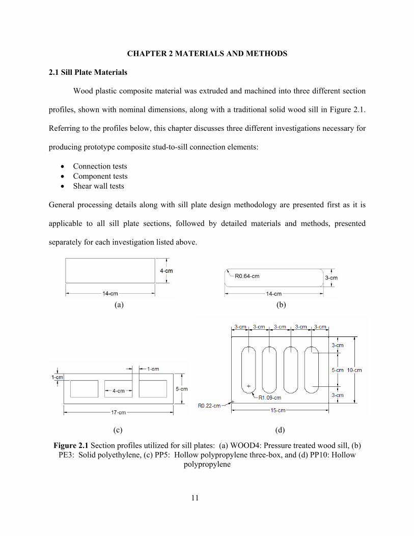
Wood plastic composite material was extruded and machined into three different section
profiles, shown with nominal dimensions, along with a traditional solid wood sill in Figure 2.1.
Referring to the profiles below, this chapter discusses three different investigations necessary for
producing prototype composite stud-to-sill connection elements:
• Connection tests • Component tests • Shear wall tests
General processing details along with sill plate design methodology are presented first as it is
applicable to all sill plate sections, followed by detailed materials and methods, presented
separately for each investigation listed above.
(a)
(b)
(c)
(d)
Figure 2.1 Section profiles utilized for sill plates: (a) WOOD4: Pressure treated wood sill, (b)
PE3: Solid polyethylene, (c) PP5: Hollow polypropylene three-box, and (d) PP10: Hollow polypropylene
12
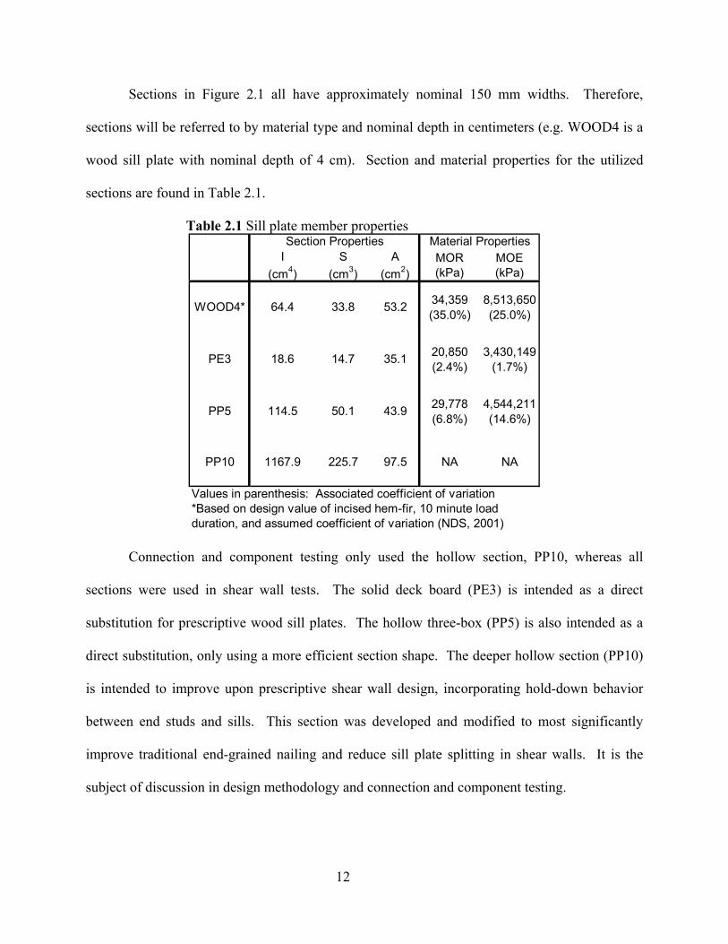
Sections in Figure 2.1 all have approximately nominal 150 mm widths. Therefore,
sections will be referred to by material type and nominal depth in centimeters (e.g. WOOD4 is a
wood sill plate with nominal depth of 4 cm). Section and material properties for the utilized
sections are found in Table 2.1.
Table 2.1 Sill plate member properties
I (cm4)
S (cm3)
A (cm2)
MOR (kPa)
MOE (kPa)
34,359 8,513,650(35.0%) (25.0%)
20,850 3,430,149(2.4%) (1.7%)
29,778 4,544,211(6.8%) (14.6%)
PP10 1167.9 225.7 97.5 NA NA
Values in parenthesis: Associated coefficient of variation*Based on design value of incised hem-fir, 10 minute load duration, and assumed coefficient of variation (NDS, 2001)
Section Properties Material Properties
WOOD4* 64.4 33.8 53.2
PE3 18.6 14.7 35.1
PP5 114.5 50.1 43.9
Connection and component testing only used the hollow section, PP10, whereas all
sections were used in shear wall tests. The solid deck board (PE3) is intended as a direct
substitution for prescriptive wood sill plates. The hollow three-box (PP5) is also intended as a
direct substitution, only using a more efficient section shape. The deeper hollow section (PP10)
is intended to improve upon prescriptive shear wall design, incorporating hold-down behavior
between end studs and sills. This section was developed and modified to most significantly
improve traditional end-grained nailing and reduce sill plate splitting in shear walls. It is the
subject of discussion in design methodology and connection and component testing.
13
The solid deck board section is a polyethylene formulation, with the following
constituents:
57.0% 60 Mesh Pine flour, Pinus spp. (#6020 American Wood Fibers) 30.0% HDPE (Equistar LB0010 00) 6.0% White Talc (Luzenac Nicron 403) 2.0% Zinc Stearate (Ferro Chemicals Synpro DLG-20B) 2.0% Zinc Borate (US Borax Boroguard) 2.0% Pigment (Ciba) 1.0% EBS Wax (GE Specialty Chemicals N, N’-thylene-bisstearamide)
Both hollow sections were a polypropylene formulation, chosen based on results from a previous
polypropylene formulation study (Slaughter, 2004). This formulation maximizes mechanical and
physical properties while providing quality extrusion characteristics. The following is the list of
formulation constituents:
58.83% Isotactic Polypropylene Homopolymer (Solvay HB9200) 33.83% 60 Mesh Pine flour, Pinus spp. (#6020 American Wood Fibers) 4.0% White Talc (Luzenac Nicron 403) 2.3% MAPP, Maleated Polypropylene Copolymer (Honeywell A-C 950P) 1.0% OptiPak-100, Polyester-based wax (Honeywell OP-100)
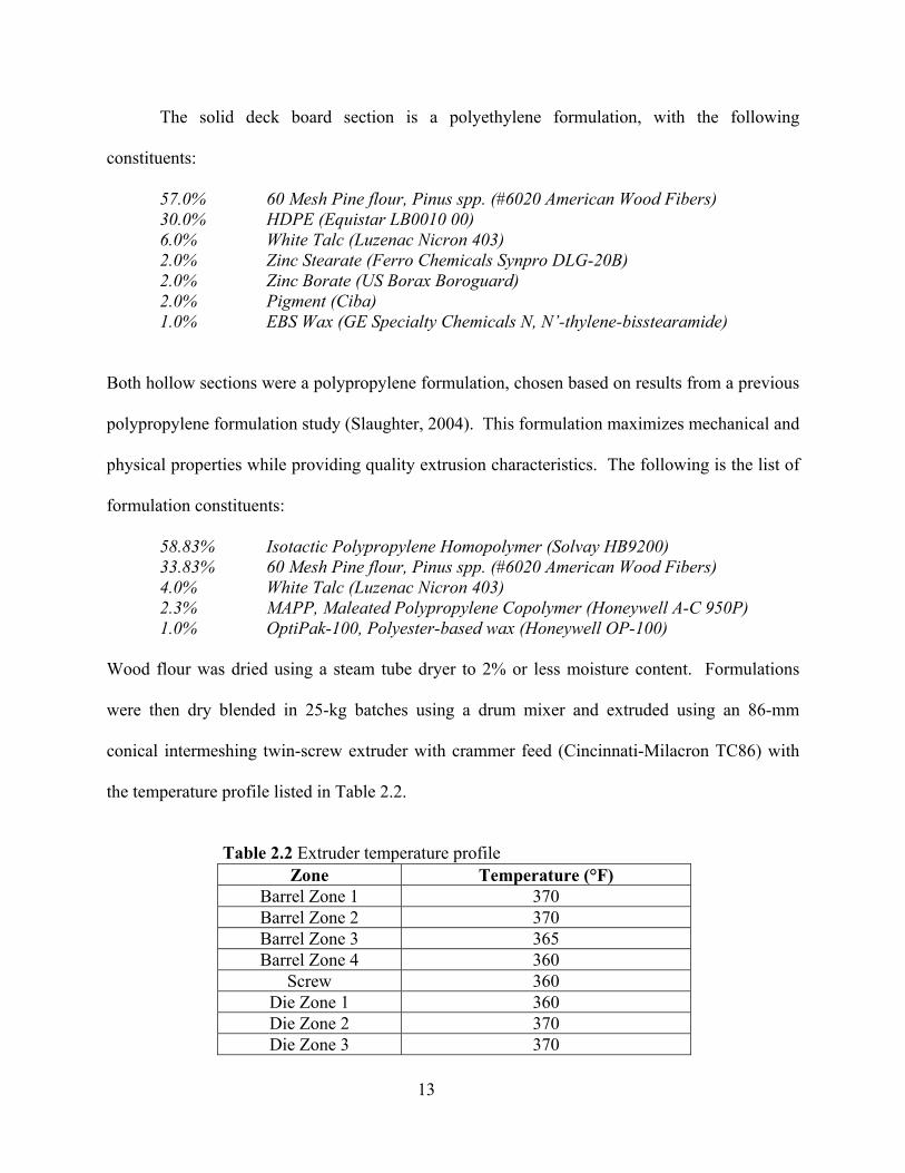
Wood flour was dried using a steam tube dryer to 2% or less moisture content. Formulations
were then dry blended in 25-kg batches using a drum mixer and extruded using an 86-mm
conical intermeshing twin-screw extruder with crammer feed (Cincinnati-Milacron TC86) with
the temperature profile listed in Table 2.2.
Table 2.2 Extruder temperature profile
Zone Temperature (°F) Barrel Zone 1 370 Barrel Zone 2 370 Barrel Zone 3 365 Barrel Zone 4 360
Screw 360 Die Zone 1 360 Die Zone 2 370 Die Zone 3 370
14
The screw rotational rate was 10 rpms for PE3, 5-12 rpms for PP10, and 8 rpms for PP5, with
both PP10 and PP5 utilizing stranding plate technology (Laver, 1996). The extrudate was cooled
in a water bath after exiting the die.
2.2 Design Methodology
Current shear wall design methods concentrate overturning forces at the sill plate. In
conventional construction, walls are anchored to foundations using shear bolts or nails. The
uplift forces are then transferred from the end stud and sheathing into the sill plate through
sheathing nails, because the framing nails have zero force resistance when oriented in the end-
grain of the lumber. From the sill plate, loads are transferred into foundations through anchor
bolts or nails. However, engineered construction includes additional hold-down hardware to
directly transfer uplift forces from end studs into foundations.
In developing a prototype of our composite sill plate, certain restrictions and design goals
had to be met. To use conventional stud lengths, it was necessary to maintain 38-mm (2x
nominal) thicknesses in the sill plate at stud locations. At the same time, the sill plate should
allow placement of sheathing 152-mm (6-in) up from bottom edges to avoid moisture contact.
By approaching the design from a system stand point, the need for measuring in the field may be
eliminated along with the need for foundation anchors, large washers, and hold-down hardware.
To accomplish design goals, the prototype WPC sill plate will conceptually have an L-shaped
cross section. Ideally, the bottom surface would be 38-mm (2x nominal) thickness and the side
section would stand 152-mm (6-in). The prototype used existing cross-sections; therefore,
dimensions represent intended design. The basic concept, illustrated in Figure 2.2, provided the
necessary dimensions at studs, clearance of sheathing, and additional connection options
between studs and sills to accomplish performance requirements. Hold-down hardware in

15
engineered construction, limits the uplift sill plates undergo. However, it also increases
construction expense as well as the need for quality control. Therefore, the prototype sill plate
incorporates the hold-down behavior within the stud-to-sill connections.
Members were machined to create slots at stud locations providing a place for studs and
an ability to fasten through side walls into stud edges as shown in Figure 2.3. Uplift resistance
was achieved by the lateral resistance of fasteners installed through the sill side into studs,
perpendicular to stud lengths, improving upon traditional end nailed connections (having
negligible withdrawal/uplift resistance). Based on this conceptual design, the following forces
must be considered in design of a composite sill plate system:
• Beam bending from uplift forces in end studs (tension), illustrated in Figure 2.4.
• Compression from opposite chord in overturning resistance (end stud), illustrated in
Figure 2.5.
• Cross grain bending due to the eccentricity between upward forces from sheathing
nails and restraint of anchor bolts, illustrated in Figure 2.6.
• Bearing and tension perpendicular-to-extrusion at connections, illustrated in
Figure 2.7.
Calculations based on simple mechanics’ assumptions indicate that the highest stresses
will occur in tension perpendicular-to-extrusion at connections.
Figure 2.2 Conceptual sill plate system
16
(a) (b)
Figure 2.3 Machined stud locations: a) End stud, b) Interior stud
Figure 2.4 Beam bending of sill plate due to
tension from overturning forces
Figure 2.5 Compressive forces on sill plate from compression chord (end studs) in wall
overturning
Figure 2.6 Cross-grain bending of sill plate due to eccentricity between sheathing connection and anchor
17
(a) (b) (c) Figure 2.7 Connection forces: (a) End stud connection force direction, (b) Bearing on sill plate
from fasteners, (c) Tension perpendicular to extrusion from upward force of fastener
2.3 Connection Test Materials and Methods
Design of the connection between double end studs and the hollow composite sill plate
(PP10) required design values for the sill for tension in the perpendicular-to-extrusion direction.
Because these values have not been determined for the formulation used, design became difficult.
Connection tests were required to isolate this end stud/sill connection. Tests investigated:
• Methods of attachment (e.g. number of fasteners, amount of edge distance, toe nails)
• Configuration changes (e.g. end stud location, anchor bolt locations)
• Transverse reinforcement effects (e.g. installing screws, fiberglass/PP tape)
Connection tests were conducted on PP10, in which specimens were cut to 254-mm (10-
in) in length. Slots for end studs had dimensions as shown in Figure 2.8, with 11 specimens
having slots machined in one end, and 5 specimens having a shifted configuration wtih slots
machined 127-mm (5-in) O.C. from the end.
Wood members for end studs were two 381-mm (15-in) long pieces of 38-mm x 140-mm
(2-in x 6-in nominal) dimensional lumber graded as Select Structural Douglas-fir. Because of
limitations in machining rounded interior corners in composite sections, bottom corners of end
studs were cut at 45 degrees, approximately 6-mm (¼ in) up from the end.
18
Connections of the studs to specimens were through the 15-mm (0.6-in) thick vertical
wall remaining of the composite sill after machining. A typical connection is shown in Figure
2.9, with the only connection occurring through section sidewalls. The end stud/sill connection
geometry and type of fastener is specified for each test in the summary table located in Appendix
A. Stud-to-sill connections used wood screws and helical threaded nails. Helical threaded nail
diameters were approximately 50% less than wood screws (3.4-mm (0.135-in)), with similar
stiffness. When installing the screws, a pilot hole equal to the fastener diameter prevented
splitting of the WPC and allowed fasteners to insert completely. Pre-drilling the wood studs with
a 4-mm (9/64-in) hole facilitated completely inserting screws while preventing splits. Predrilled
holes in WPC specimens for utilizing helical threaded nails had a diameter of 3.1-mm (0.125-
in.).
(a) (b)
Figure 2.8 PP10 slot dimensions: (a) Specimens 1-11 and (b) Specimens 12-16 (Shifted Configuration)

19
Figure 2.9 Typical connection test geometry
The configuration for Specimens 1-11 had the end stud located at the end of the sill, as
traditionally would be done. On the contrary, Specimens 12-16 had end studs located 127-mm
(5-in) O.C. from ends of sills, leaving 89-mm (3-1/2 in) from outside stud face to the end of the
sill, to allow an adjacent 38-mm x 89-mm (2-in x 4-in nominal) wall to be framed at the corner.
This shifted configuration also provides more surface area for connections to fully utilize the
WPC section when transferring tensile forces, compared to the configuration of Specimens 1-11,
primarily having only the sidewall into which to fasten. Two 254-mm (10-in) diameter A36 steel
dowels were inserted through the two center cavities of the WPC section and through the end
stud—allowing 89-mm (3-1/2 in) of dowel extend from either side of end studs. Dowels were
able to bear on the sections’ top flanges from inside the hollow cavities.
Two reinforcing methods were used to improve transverse properties. The first, used
fiberglass reinforced PP tape which was melt bonded to the sill surface, with fibers oriented
parallel to the tension force direction. The second method consisted of fine thread drywall
screws with length of 64 mm (#8 x 2-1/2 in) inserted through sill flanges and into webs
(predrilled to 3.1 mm (1/8-in) diameter).
A summary of test variables is in Table 2.3.
20
Table 2.3 Connection Test Variables Test Stud/Sill Attachment Method Configuration Reinforcing
1 2 3 4 5 6
Wood screws
7 Helical nails 8 Wood screws 9 Helical nails
NA
10 Drywall screws 11
Traditional
Fiberglass/PP screws12
Wood screws
13 14
NA
15 Wood screws, dowels
Drywall screws 16 Dowels
Shifted end stud and
anchor bolt location
Drywall screws
Monotonic testing of end stud-sill connections was conducted under displacement-
controlled loading after conditioning for WPC sill plates took place for a minimum of 160 hours
at 50% RH and 21.1 degrees Celsius. End studs were conditioned for a minimum of 184 hours at
65% RH and 20 degrees Celsius until moisture contents were near 12%. Loading rates
determined by ASTM D790 (Flexural Properties of Reinforced and Unreinforced Plastics) were
difficult to apply to this unique section shape. The loading rate was modified from Bolted
Connections in Wood and Wood-Based Products (ASTM D 5652) and Standard Test Methods
for Mechanical Fasteners in Wood (ASTM D1761-88) to be 5 mm/min (0.20 in/min). Previous
testing by Smart (2002) at Virginia Tech showed no appreciable difference in strength when
increasing the load rate from 2.5 mm/min (0.10 in/min).
Tensile loads were applied with a 30-kip universal electromechanical test machine
(Instron 4400R), simulating tension forces that occur in end studs as walls overturn. The test
setup is illustrated in Figure 2.10. The end studs were positioned between two steel plates
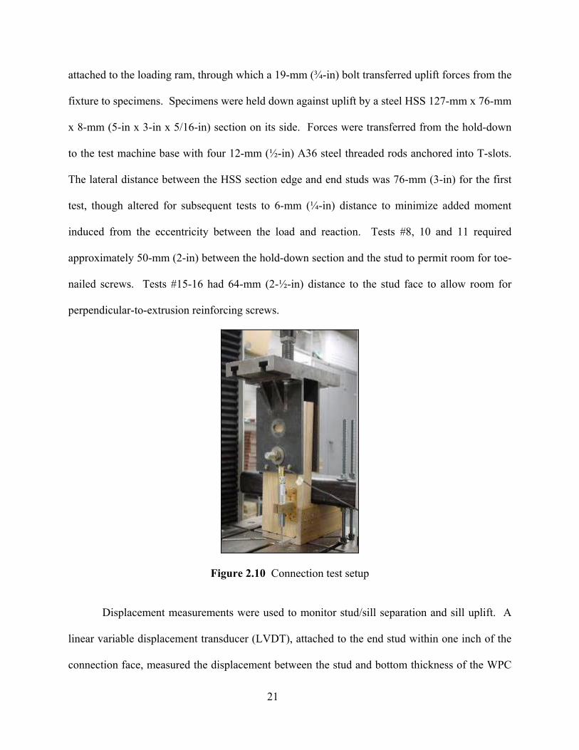
21
attached to the loading ram, through which a 19-mm (¾-in) bolt transferred uplift forces from the
fixture to specimens. Specimens were held down against uplift by a steel HSS 127-mm x 76-mm
x 8-mm (5-in x 3-in x 5/16-in) section on its side. Forces were transferred from the hold-down
to the test machine base with four 12-mm (½-in) A36 steel threaded rods anchored into T-slots.
The lateral distance between the HSS section edge and end studs was 76-mm (3-in) for the first
test, though altered for subsequent tests to 6-mm (¼-in) distance to minimize added moment
induced from the eccentricity between the load and reaction. Tests #8, 10 and 11 required
approximately 50-mm (2-in) between the hold-down section and the stud to permit room for toe-
nailed screws. Tests #15-16 had 64-mm (2-½-in) distance to the stud face to allow room for
perpendicular-to-extrusion reinforcing screws.
Figure 2.10 Connection test setup
Displacement measurements were used to monitor stud/sill separation and sill uplift. A
linear variable displacement transducer (LVDT), attached to the end stud within one inch of the
connection face, measured the displacement between the stud and bottom thickness of the WPC
22
sill to quantify stud and sill separation. The crosshead extension reading of the test machine was
used to measure total uplift. Testing continued until a visual connection failure occurred and
load resistance reached 80% post-peak load.
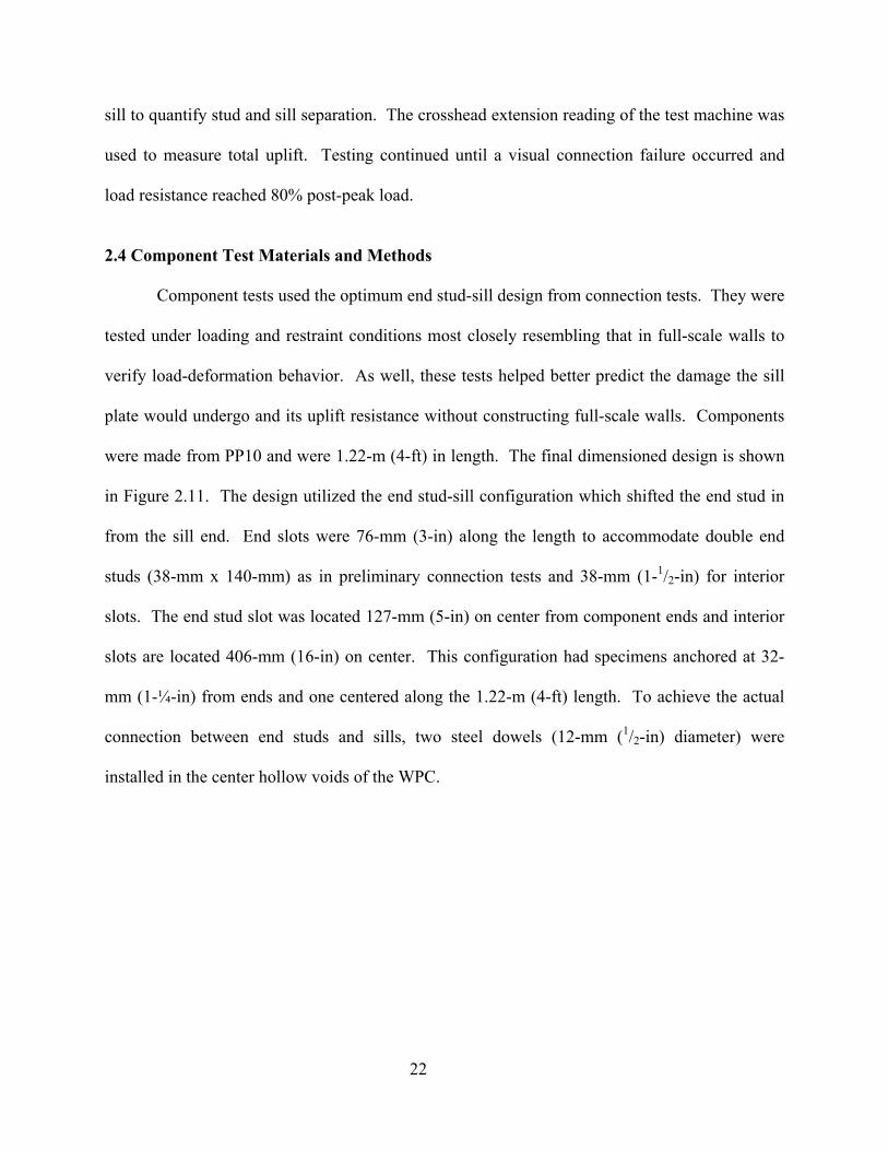
2.4 Component Test Materials and Methods
Component tests used the optimum end stud-sill design from connection tests. They were
tested under loading and restraint conditions most closely resembling that in full-scale walls to
verify load-deformation behavior. As well, these tests helped better predict the damage the sill
plate would undergo and its uplift resistance without constructing full-scale walls. Components
were made from PP10 and were 1.22-m (4-ft) in length. The final dimensioned design is shown
in Figure 2.11. The design utilized the end stud-sill configuration which shifted the end stud in
from the sill end. End slots were 76-mm (3-in) along the length to accommodate double end
studs (38-mm x 140-mm) as in preliminary connection tests and 38-mm (1-1/2-in) for interior
slots. The end stud slot was located 127-mm (5-in) on center from component ends and interior
slots are located 406-mm (16-in) on center. This configuration had specimens anchored at 32-
mm (1-¼-in) from ends and one centered along the 1.22-m (4-ft) length. To achieve the actual
connection between end studs and sills, two steel dowels (12-mm (1/2-in) diameter) were
installed in the center hollow voids of the WPC.
23
(a)
(b)
Figure 2.11 Component design: a) Full section, b) End stud detail
Utilizing reinforcement aimed to improve transverse properties. Tension forces
perpendicular-to-extrusion direction were countered with three drywall screws in interior webs
on both sides of end studs, along with the bottom outside wall at the end stud sidewall
connection.
Perpendicular-to-extrusion reinforcement screws
Dimensions from bottom indicate location of perpendicular-to-extrusion reinforcement screws
Wood screws
24
Lumber for studs was No. 2 and Better grade Douglas-fir, with 38-mm x 140-mm (2-in x
6-in nominal) dimensions. Interior studs were 127-mm (5-in) long, acting only as placeholders
in machined slots as they did not resist or apply load to specimens—only accounting for stiffness
changes and localized stresses where interior portions of webs were removed from net cross
sections. End studs were doubled and 381-mm (15-in) in length.
Test setups were similar to those used for the connection tests and are shown in Figure
2.12. The loading ram was connected to end studs using a 19-mm (¾-in) bolt, 152-mm (6-in)
from the upper end of studs, using four wood screws (two on each side). Uplift reactions were
12-mm (½-in) A36 anchor bolts extending from beneath the steel double channel sections on the
test machine to the top of WPC sections. Initial testing used only one bolt at 32-mm (1-¼-in) at
each end, though unrealistic upward bending was occurring at mid-span from no restraint from
studs, so a middle bolt was added for remaining replicates. Holes for anchor bolts were 14-mm
(9/16-in) and were secured with a nut and plate washer. As anchor bolts were inserted in both sill
plate ends for each test, only the loaded end resisted the majority of the uplift and allowed
twenty-eight tests to be completed from fourteen 1.22-m (4-ft) long specimens.
Methods for component tests followed ASTM E529-94. Displacement was applied at 5
mm/min (0.2 in/min) similar to previous connection tests, and applied in tension in the 30-kip
universal electromechanical test machine (Instron 4400R). Displacement was applied until load
decreased to 80% of peak load. Displacement measurements were taken with the crosshead
extension for overall displacement and with two string pots to determine rotational behavior of
sills. String pot measures were centered at end studs (center of load application) on opposite
edges of WPC sill plates.
25
(a) (b)
Figure 2.12 Component test setup: a) Full component, b) End stud detail
2.5 Shear Wall Test Materials and Methods
Full-scale tests of shear walls constructed with wood-plastic composite (WPC) sill plates
provided final data needed to characterize prototype wall-foundation connector elements. Wall
configurations included sill plates described previously in this chapter, testing a control wall, two
walls with equal replacement sills, and one with expected performance improvements from stud-
sill connection improvement. Tests of various wall configurations allowed comparison of wall
deflection and load capacity with current shear wall designs. As well, tests demonstrated
changes in sill plate behavior, in distribution of uplift forces to anchor bolts, and in wall failure
modes.
The following discussion outlines test materials and procedures used.
26
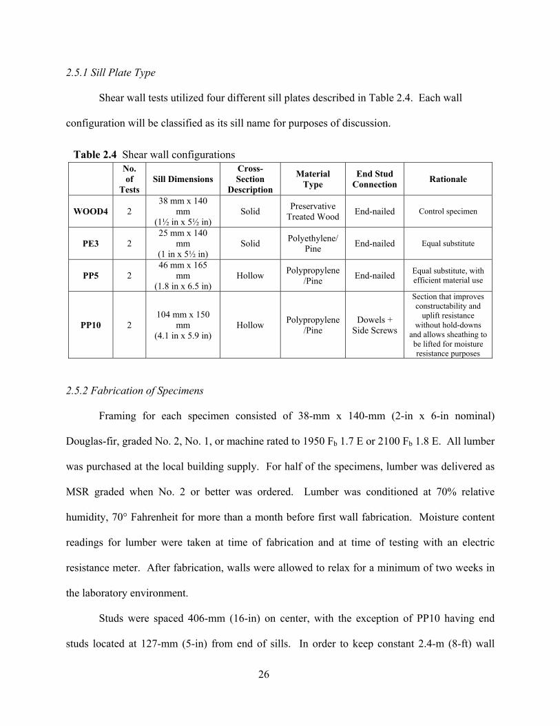
2.5.1 Sill Plate Type
Shear wall tests utilized four different sill plates described in Table 2.4. Each wall
configuration will be classified as its sill name for purposes of discussion.
2.5.2 Fabrication of Specimens
Framing for each specimen consisted of 38-mm x 140-mm (2-in x 6-in nominal)
Douglas-fir, graded No. 2, No. 1, or machine rated to 1950 Fb 1.7 E or 2100 Fb 1.8 E. All lumber
was purchased at the local building supply. For half of the specimens, lumber was delivered as
MSR graded when No. 2 or better was ordered. Lumber was conditioned at 70% relative
humidity, 70° Fahrenheit for more than a month before first wall fabrication. Moisture content
readings for lumber were taken at time of fabrication and at time of testing with an electric
resistance meter. After fabrication, walls were allowed to relax for a minimum of two weeks in
the laboratory environment.
Studs were spaced 406-mm (16-in) on center, with the exception of PP10 having end
studs located at 127-mm (5-in) from end of sills. In order to keep constant 2.4-m (8-ft) wall
Table 2.4 Shear wall configurations
No. of
Tests Sill Dimensions
Cross-Section
Description
Material Type
End Stud Connection Rationale
WOOD4 2 38 mm x 140
mm (1½ in x 5½ in)
Solid Preservative Treated Wood End-nailed Control specimen
PE3 2 25 mm x 140
mm (1 in x 5½ in)
Solid Polyethylene/ Pine End-nailed Equal substitute
PP5 2 46 mm x 165
mm (1.8 in x 6.5 in)
Hollow Polypropylene/Pine End-nailed Equal substitute, with
efficient material use
PP10 2 104 mm x 150
mm (4.1 in x 5.9 in)
Hollow Polypropylene/Pine
Dowels + Side Screws
Section that improves constructability and
uplift resistance without hold-downs
and allows sheathing to be lifted for moisture resistance purposes
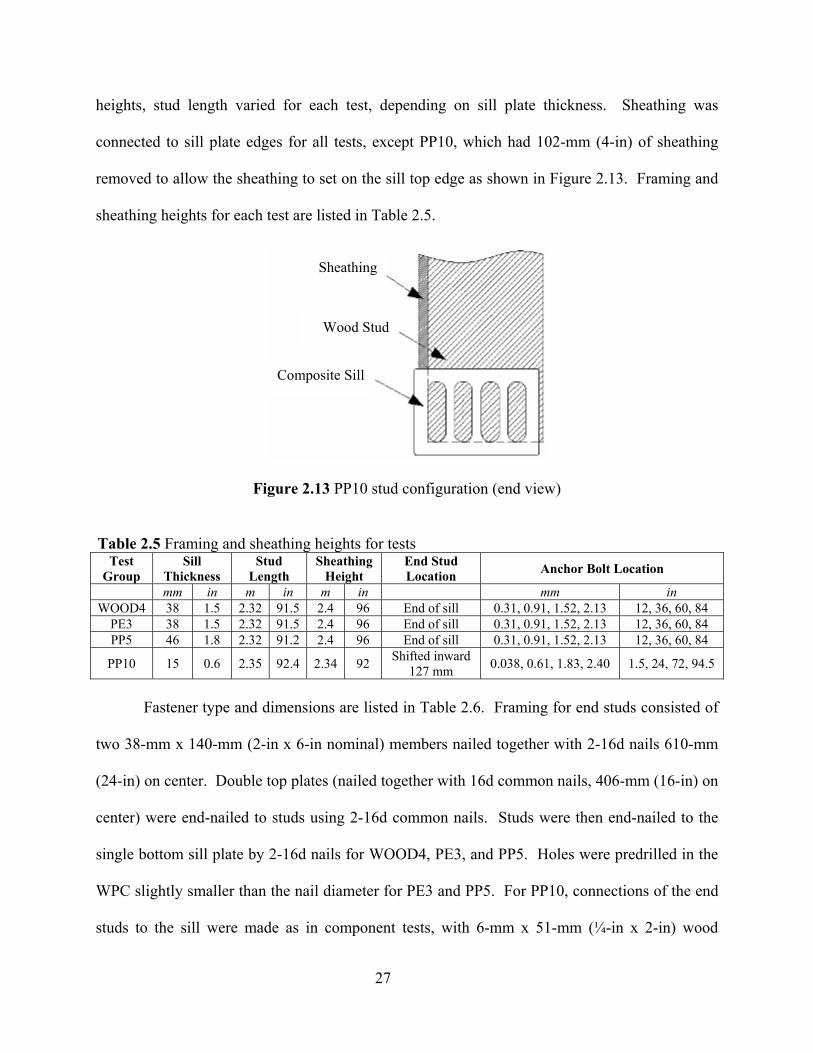
27
heights, stud length varied for each test, depending on sill plate thickness. Sheathing was
connected to sill plate edges for all tests, except PP10, which had 102-mm (4-in) of sheathing
removed to allow the sheathing to set on the sill top edge as shown in Figure 2.13. Framing and
sheathing heights for each test are listed in Table 2.5.
Figure 2.13 PP10 stud configuration (end view)
Table 2.5 Framing and sheathing heights for tests Test
Group Sill
Thickness Stud
Length Sheathing
Height End Stud Location Anchor Bolt Location
mm in m in m in mm in WOOD4 38 1.5 2.32 91.5 2.4 96 End of sill 0.31, 0.91, 1.52, 2.13 12, 36, 60, 84
PE3 38 1.5 2.32 91.5 2.4 96 End of sill 0.31, 0.91, 1.52, 2.13 12, 36, 60, 84 PP5 46 1.8 2.32 91.2 2.4 96 End of sill 0.31, 0.91, 1.52, 2.13 12, 36, 60, 84
PP10 15 0.6 2.35 92.4 2.34 92 Shifted inward 127 mm 0.038, 0.61, 1.83, 2.40 1.5, 24, 72, 94.5
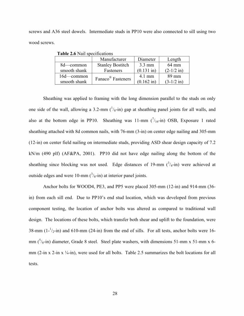
Fastener type and dimensions are listed in Table 2.6. Framing for end studs consisted of
two 38-mm x 140-mm (2-in x 6-in nominal) members nailed together with 2-16d nails 610-mm
(24-in) on center. Double top plates (nailed together with 16d common nails, 406-mm (16-in) on
center) were end-nailed to studs using 2-16d common nails. Studs were then end-nailed to the
single bottom sill plate by 2-16d nails for WOOD4, PE3, and PP5. Holes were predrilled in the
WPC slightly smaller than the nail diameter for PE3 and PP5. For PP10, connections of the end
studs to the sill were made as in component tests, with 6-mm x 51-mm (¼-in x 2-in) wood
Sheathing
Wood Stud
Composite Sill
28
screws and A36 steel dowels. Intermediate studs in PP10 were also connected to sill using two
wood screws.
Table 2.6 Nail specifications Manufacturer Diameter Length
8d—common smooth shank
Stanley Bostitch Fasteners
3.3 mm (0.131 in)
64 mm (2-1/2 in)
16d—common smooth shank Fanaco® Fasteners 4.1 mm
(0.162 in) 89 mm
(3-1/2 in)
Sheathing was applied to framing with the long dimension parallel to the studs on only
one side of the wall, allowing a 3.2-mm (1/8-in) gap at sheathing panel joints for all walls, and
also at the bottom edge in PP10. Sheathing was 11-mm (7/16-in) OSB, Exposure 1 rated
sheathing attached with 8d common nails, with 76-mm (3-in) on center edge nailing and 305-mm
(12-in) on center field nailing on intermediate studs, providing ASD shear design capacity of 7.2
kN/m (490 plf) (AF&PA, 2001). PP10 did not have edge nailing along the bottom of the
sheathing since blocking was not used. Edge distances of 19-mm (3/4-in) were achieved at
outside edges and were 10-mm (3/8-in) at interior panel joints.
Anchor bolts for WOOD4, PE3, and PP5 were placed 305-mm (12-in) and 914-mm (36-
in) from each sill end. Due to PP10’s end stud location, which was developed from previous
component testing, the location of anchor bolts was altered as compared to traditional wall
design. The locations of these bolts, which transfer both shear and uplift to the foundation, were
38-mm (1-1/2-in) and 610-mm (24-in) from the end of sills. For all tests, anchor bolts were 16-
mm (5/8-in) diameter, Grade 8 steel. Steel plate washers, with dimensions 51-mm x 51-mm x 6-
mm (2-in x 2-in x ¼-in), were used for all bolts. Table 2.5 summarizes the bolt locations for all
tests.
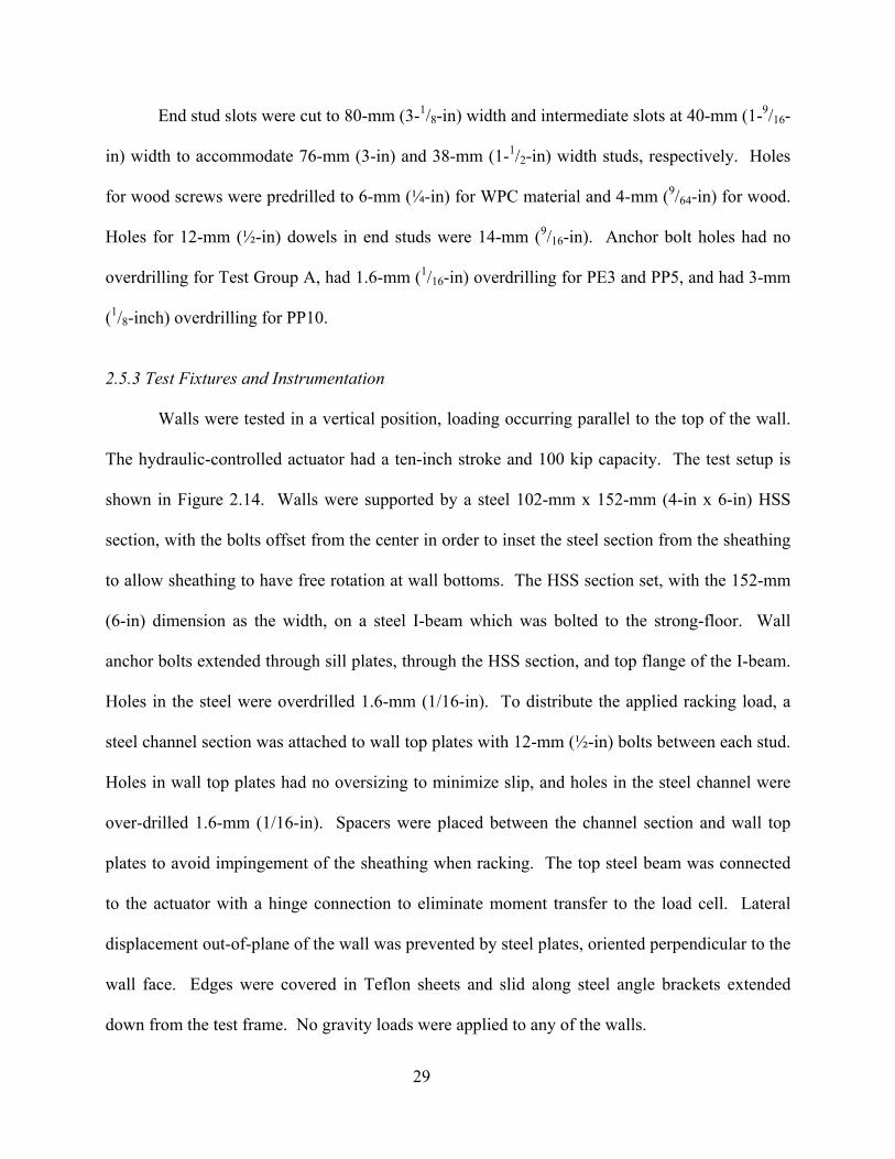
29
End stud slots were cut to 80-mm (3-1/8-in) width and intermediate slots at 40-mm (1-9/16-
in) width to accommodate 76-mm (3-in) and 38-mm (1-1/2-in) width studs, respectively. Holes
for wood screws were predrilled to 6-mm (¼-in) for WPC material and 4-mm (9/64-in) for wood.
Holes for 12-mm (½-in) dowels in end studs were 14-mm (9/16-in). Anchor bolt holes had no
overdrilling for Test Group A, had 1.6-mm (1/16-in) overdrilling for PE3 and PP5, and had 3-mm
(1/8-inch) overdrilling for PP10.
2.5.3 Test Fixtures and Instrumentation
Walls were tested in a vertical position, loading occurring parallel to the top of the wall.
The hydraulic-controlled actuator had a ten-inch stroke and 100 kip capacity. The test setup is
shown in Figure 2.14. Walls were supported by a steel 102-mm x 152-mm (4-in x 6-in) HSS
section, with the bolts offset from the center in order to inset the steel section from the sheathing
to allow sheathing to have free rotation at wall bottoms. The HSS section set, with the 152-mm
(6-in) dimension as the width, on a steel I-beam which was bolted to the strong-floor. Wall
anchor bolts extended through sill plates, through the HSS section, and top flange of the I-beam.
Holes in the steel were overdrilled 1.6-mm (1/16-in). To distribute the applied racking load, a
steel channel section was attached to wall top plates with 12-mm (½-in) bolts between each stud.
Holes in wall top plates had no oversizing to minimize slip, and holes in the steel channel were
over-drilled 1.6-mm (1/16-in). Spacers were placed between the channel section and wall top
plates to avoid impingement of the sheathing when racking. The top steel beam was connected
to the actuator with a hinge connection to eliminate moment transfer to the load cell. Lateral
displacement out-of-plane of the wall was prevented by steel plates, oriented perpendicular to the
wall face. Edges were covered in Teflon sheets and slid along steel angle brackets extended
down from the test frame. No gravity loads were applied to any of the walls.

30
Load and deflection measurements were taken at the locations identified in Figure 2.15.
Load measurements for tension in anchor bolts were made with Omega LC901-3/4-65k bolt
force sensors wired through digital strain indicators. Load washers were placed on top of plate
washers (code-required), below bolt heads. Displacement measures were all taken with
resistance potentiometers (string pots) with maximum 254-mm (10-in) displacement ranges. The
exception was Displacement Measure 9, which used a 51-mm (2-in) displacement pot.
Lateral Bracing
Steel beams anchored to strong-floor
Hydraulic actuator
Figure 2.14 Shear wall test frame
LOAD MEASUREMENTS
13 South Stud Uplift12 South Sill Uplift11 North Stud Uplift10 North Sill Uplift9 Bottom Slip8 Top Beam Displacement7 Wall Displacement6 Actuator Feedback
4 Anchor Bolt 33 Anchor Bolt 22 Anchor Bolt 11 Actuator Load Cell
16 7
8
4 3 29
12
13
10
11
DISPLACEMENT MEASUREMENTS
Figure 2.15 Shear wall test instrumentation
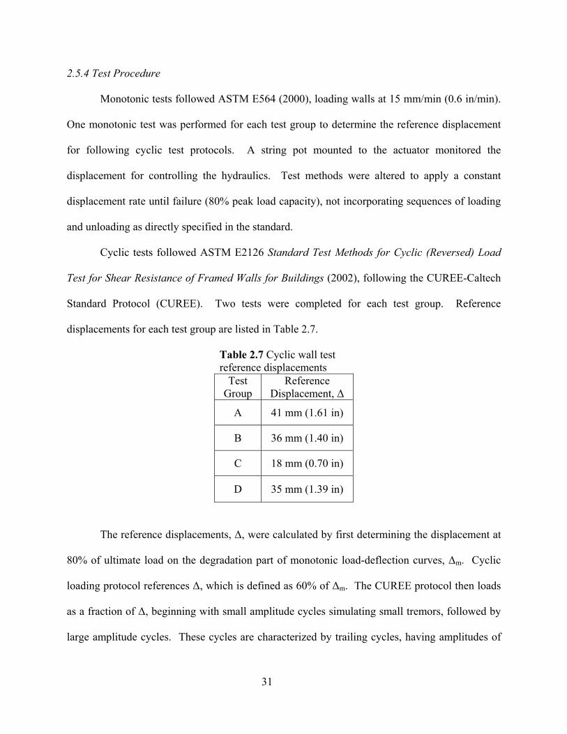
31
2.5.4 Test Procedure
Monotonic tests followed ASTM E564 (2000), loading walls at 15 mm/min (0.6 in/min).
One monotonic test was performed for each test group to determine the reference displacement
for following cyclic test protocols. A string pot mounted to the actuator monitored the
displacement for controlling the hydraulics. Test methods were altered to apply a constant
displacement rate until failure (80% peak load capacity), not incorporating sequences of loading
and unloading as directly specified in the standard.
Cyclic tests followed ASTM E2126 Standard Test Methods for Cyclic (Reversed) Load
Test for Shear Resistance of Framed Walls for Buildings (2002), following the CUREE-Caltech
Standard Protocol (CUREE). Two tests were completed for each test group. Reference
displacements for each test group are listed in Table 2.7.
Table 2.7 Cyclic wall test reference displacements
Test Group
Reference Displacement, ∆
A 41 mm (1.61 in)
B 36 mm (1.40 in)
C 18 mm (0.70 in)
D 35 mm (1.39 in)
The reference displacements, ∆, were calculated by first determining the displacement at
80% of ultimate load on the degradation part of monotonic load-deflection curves, ∆m. Cyclic
loading protocol references ∆, which is defined as 60% of ∆m. The CUREE protocol then loads
as a fraction of ∆, beginning with small amplitude cycles simulating small tremors, followed by
large amplitude cycles. These cycles are characterized by trailing cycles, having amplitudes of
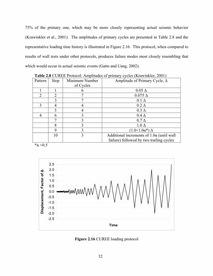
32
75% of the primary one, which may be more closely representing actual seismic behavior
(Krawinkler et al., 2001). The amplitudes of primary cycles are presented in Table 2.8 and the
representative loading time history is illustrated in Figure 2.16. This protocol, when compared to
results of wall tests under other protocols, produces failure modes most closely resembling that
which would occur in actual seismic events (Gatto and Uang, 2002).
Table 2.8 CUREE Protocol: Amplitudes of primary cycles (Krawinkler, 2001) Pattern Step Minimum Number
of Cycles Amplitude of Primary Cycle, ∆
1 1 6 0.05 ∆ 2 2 7 0.075 ∆ 3 7 0.1 ∆ 3 4 4 0.2 ∆ 5 4 0.3 ∆ 4 6 3 0.4 ∆ 7 3 0.7 ∆ 8 3 1.0 ∆ 9 3 (1.0+1.0α*) ∆ 10 3 Additional increments of 1.0α (until wall
failure) followed by two trailing cycles *α <0.5
-2.5-2.0-1.5-1.0-0.50.00.51.01.52.02.5
Time
Dis
plac
emen
t, Fa
ctor
of ∆
Figure 2.16 CUREE loading protocol

33
A constant rate of loading, 437 mm/min (17.2 in/min), was followed for this protocol for
all wall tests, up to the point of instrument limitation. Because of the range of amplitudes
required for the full loading program, this constant rate of loading caused frequencies to extend
outside the range required by the standard (0.2-1.0 Hz). When exceeded on the high frequency
side, amplitudes were low, in initiation cycles, and should not have caused inertial effects. As
well, for higher displacement amplitude cycles, frequencies were required to drop below 0.1 Hz,
though due to limitations in the 407 controller, a frequency of 0.1 Hz was employed and rate of
loading was adjusted accordingly.
Tests continued until the primary cycles’ maximum load dropped below 80% peak
capacity. An exception was for Test 4-2, which was stopped after the 2.5∆ cycle when the
actuator stroke capacity limited further cycling.
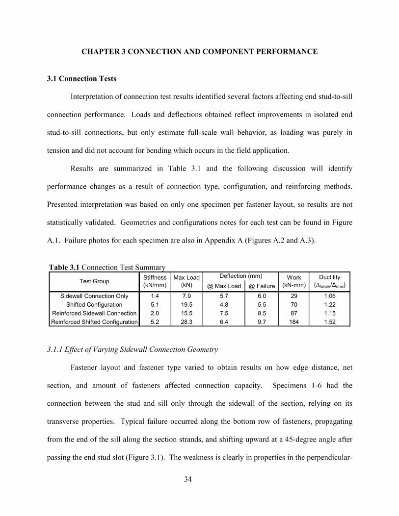
34
CHAPTER 3 CONNECTION AND COMPONENT PERFORMANCE
3.1 Connection Tests
Interpretation of connection test results identified several factors affecting end stud-to-sill
connection performance. Loads and deflections obtained reflect improvements in isolated end
stud-to-sill connections, but only estimate full-scale wall behavior, as loading was purely in
tension and did not account for bending which occurs in the field application.
Results are summarized in Table 3.1 and the following discussion will identify
performance changes as a result of connection type, configuration, and reinforcing methods.
Presented interpretation was based on only one specimen per fastener layout, so results are not
statistically validated. Geometries and configurations notes for each test can be found in Figure
A.1. Failure photos for each specimen are also in Appendix A (Figures A.2 and A.3).
Table 3.1 Connection Test Summary
@ Max Load @ Failure
Sidewall Connection Only 1.4 7.9 5.7 6.0 29 1.06Shifted Configuration 5.1 19.5 4.8 5.5 70 1.22
Reinforced Sidewall Connection 2.0 15.5 7.5 8.5 87 1.15Reinforced Shifted Configuration 5.2 28.3 6.4 9.7 184 1.52
Work (kN-mm)
Ductility (∆failure/∆max)
Test GroupDeflection (mm)Stiffness
(kN/mm)Max Load
(kN)
3.1.1 Effect of Varying Sidewall Connection Geometry
Fastener layout and fastener type varied to obtain results on how edge distance, net
section, and amount of fasteners affected connection capacity. Specimens 1-6 had the
connection between the stud and sill only through the sidewall of the section, relying on its
transverse properties. Typical failure occurred along the bottom row of fasteners, propagating
from the end of the sill along the section strands, and shifting upward at a 45-degree angle after
passing the end stud slot (Figure 3.1). The weakness is clearly in properties in the perpendicular-
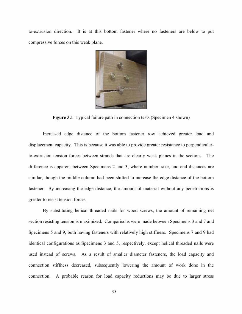
35
to-extrusion direction. It is at this bottom fastener where no fasteners are below to put
compressive forces on this weak plane.
Figure 3.1 Typical failure path in connection tests (Specimen 4 shown)
Increased edge distance of the bottom fastener row achieved greater load and
displacement capacity. This is because it was able to provide greater resistance to perpendicular-
to-extrusion tension forces between strands that are clearly weak planes in the sections. The
difference is apparent between Specimens 2 and 3, where number, size, and end distances are
similar, though the middle column had been shifted to increase the edge distance of the bottom
fastener. By increasing the edge distance, the amount of material without any penetrations is
greater to resist tension forces.
By substituting helical threaded nails for wood screws, the amount of remaining net
section resisting tension is maximized. Comparisons were made between Specimens 3 and 7 and
Specimens 5 and 9, both having fasteners with relatively high stiffness. Specimens 7 and 9 had
identical configurations as Specimens 3 and 5, respectively, except helical threaded nails were
used instead of screws. As a result of smaller diameter fasteners, the load capacity and
connection stiffness decreased, subsequently lowering the amount of work done in the
connection. A probable reason for load capacity reductions may be due to larger stress
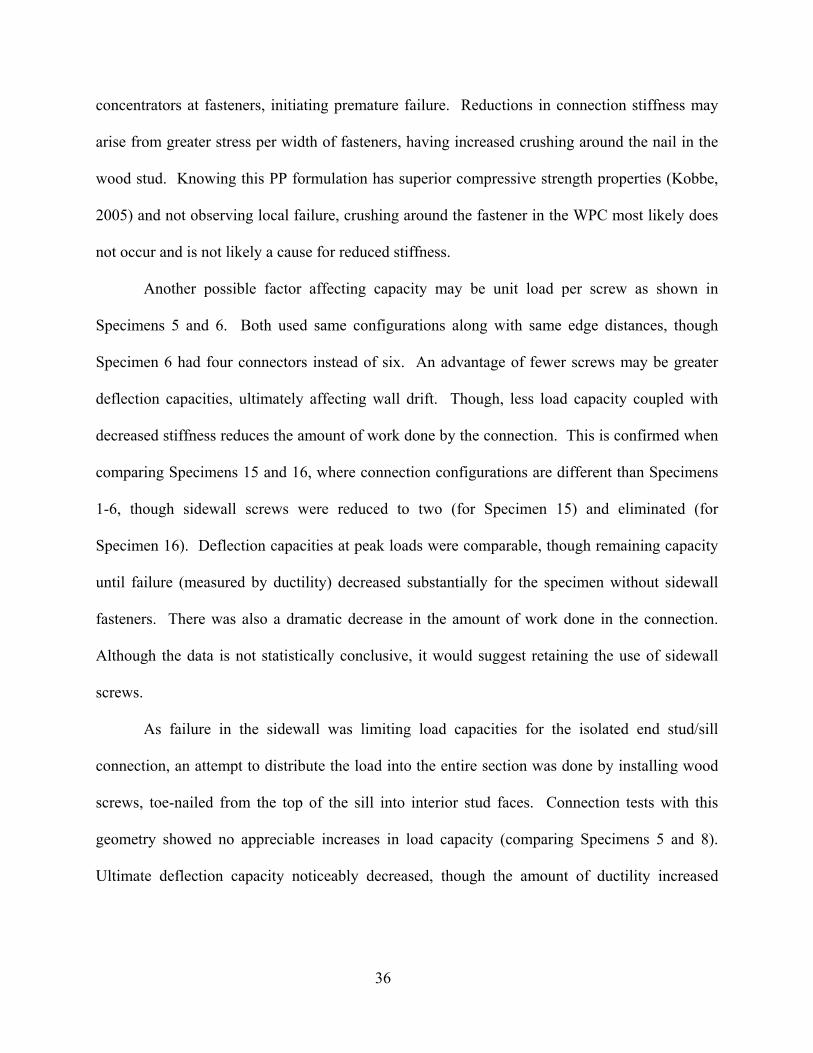
36
concentrators at fasteners, initiating premature failure. Reductions in connection stiffness may
arise from greater stress per width of fasteners, having increased crushing around the nail in the
wood stud. Knowing this PP formulation has superior compressive strength properties (Kobbe,
2005) and not observing local failure, crushing around the fastener in the WPC most likely does
not occur and is not likely a cause for reduced stiffness.
Another possible factor affecting capacity may be unit load per screw as shown in
Specimens 5 and 6. Both used same configurations along with same edge distances, though
Specimen 6 had four connectors instead of six. An advantage of fewer screws may be greater
deflection capacities, ultimately affecting wall drift. Though, less load capacity coupled with
decreased stiffness reduces the amount of work done by the connection. This is confirmed when
comparing Specimens 15 and 16, where connection configurations are different than Specimens
1-6, though sidewall screws were reduced to two (for Specimen 15) and eliminated (for
Specimen 16). Deflection capacities at peak loads were comparable, though remaining capacity
until failure (measured by ductility) decreased substantially for the specimen without sidewall
fasteners. There was also a dramatic decrease in the amount of work done in the connection.
Although the data is not statistically conclusive, it would suggest retaining the use of sidewall
screws.
As failure in the sidewall was limiting load capacities for the isolated end stud/sill
connection, an attempt to distribute the load into the entire section was done by installing wood
screws, toe-nailed from the top of the sill into interior stud faces. Connection tests with this
geometry showed no appreciable increases in load capacity (comparing Specimens 5 and 8).
Ultimate deflection capacity noticeably decreased, though the amount of ductility increased
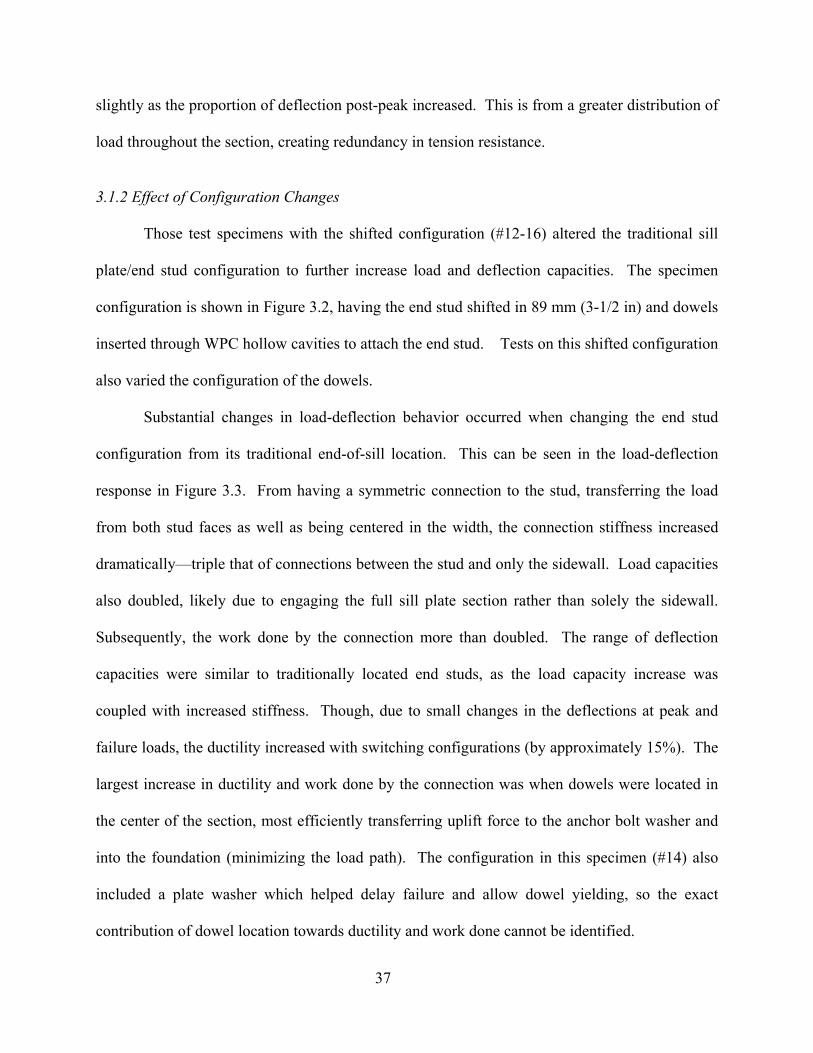
37
slightly as the proportion of deflection post-peak increased. This is from a greater distribution of
load throughout the section, creating redundancy in tension resistance.
3.1.2 Effect of Configuration Changes
Those test specimens with the shifted configuration (#12-16) altered the traditional sill
plate/end stud configuration to further increase load and deflection capacities. The specimen
configuration is shown in Figure 3.2, having the end stud shifted in 89 mm (3-1/2 in) and dowels
inserted through WPC hollow cavities to attach the end stud. Tests on this shifted configuration
also varied the configuration of the dowels.
Substantial changes in load-deflection behavior occurred when changing the end stud
configuration from its traditional end-of-sill location. This can be seen in the load-deflection
response in Figure 3.3. From having a symmetric connection to the stud, transferring the load
from both stud faces as well as being centered in the width, the connection stiffness increased
dramatically—triple that of connections between the stud and only the sidewall. Load capacities
also doubled, likely due to engaging the full sill plate section rather than solely the sidewall.
Subsequently, the work done by the connection more than doubled. The range of deflection
capacities were similar to traditionally located end studs, as the load capacity increase was
coupled with increased stiffness. Though, due to small changes in the deflections at peak and
failure loads, the ductility increased with switching configurations (by approximately 15%). The
largest increase in ductility and work done by the connection was when dowels were located in
the center of the section, most efficiently transferring uplift force to the anchor bolt washer and
into the foundation (minimizing the load path). The configuration in this specimen (#14) also
included a plate washer which helped delay failure and allow dowel yielding, so the exact
contribution of dowel location towards ductility and work done cannot be identified.
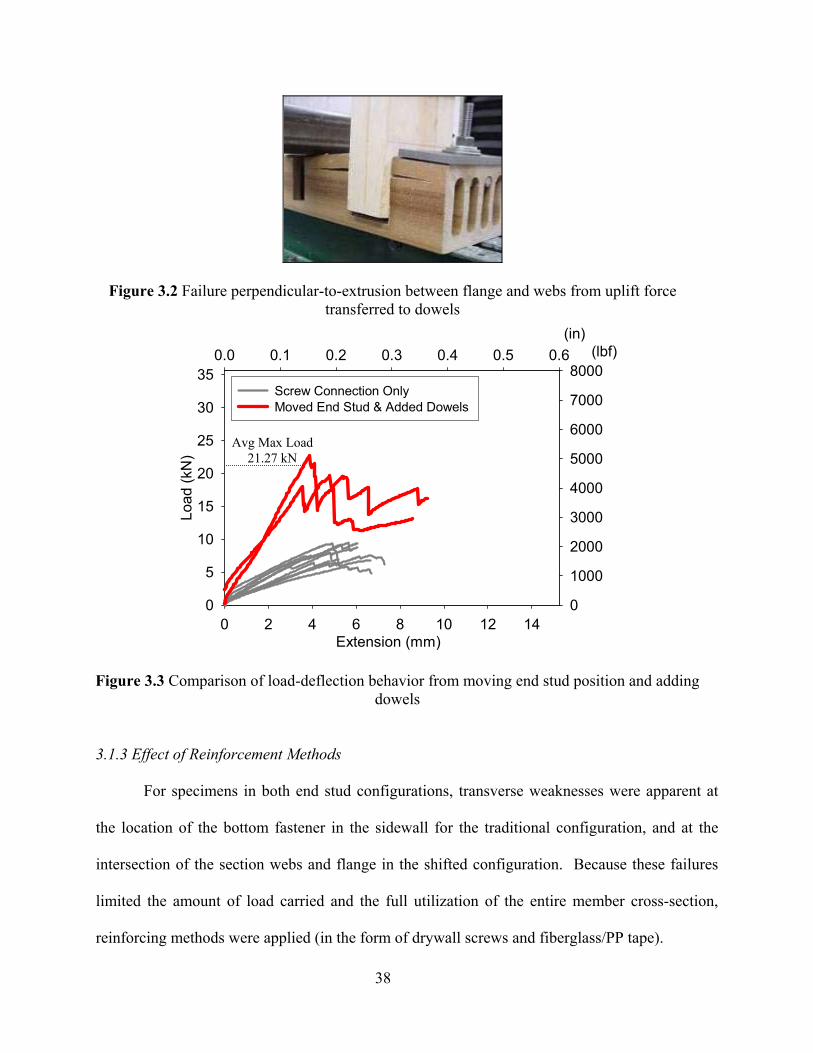
38
Figure 3.2 Failure perpendicular-to-extrusion between flange and webs from uplift force transferred to dowels
Extension (mm)0 2 4 6 8 10 12 14
Load
(kN
)
0
5
10
15
20
25
30
35Screw Connection Only Added Sidewall Perpendicular-to-Extrusion Reinforcement Moved End Stud & Added Dowels
(in)0.0 0.1 0.2 0.3 0.4 0.5 0.6 (lbf)
0
1000
2000
3000
4000
5000
6000
7000
8000Screw Connection Only Moved End Stud & Added Dowels
Figure 3.3 Comparison of load-deflection behavior from moving end stud position and adding dowels
3.1.3 Effect of Reinforcement Methods
For specimens in both end stud configurations, transverse weaknesses were apparent at
the location of the bottom fastener in the sidewall for the traditional configuration, and at the
intersection of the section webs and flange in the shifted configuration. Because these failures
limited the amount of load carried and the full utilization of the entire member cross-section,
reinforcing methods were applied (in the form of drywall screws and fiberglass/PP tape).
Avg Max Load 21.27 kN
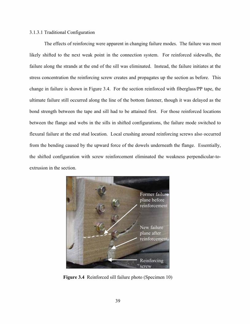
39
3.1.3.1 Traditional Configuration
The effects of reinforcing were apparent in changing failure modes. The failure was most
likely shifted to the next weak point in the connection system. For reinforced sidewalls, the
failure along the strands at the end of the sill was eliminated. Instead, the failure initiates at the
stress concentration the reinforcing screw creates and propagates up the section as before. This
change in failure is shown in Figure 3.4. For the section reinforced with fiberglass/PP tape, the
ultimate failure still occurred along the line of the bottom fastener, though it was delayed as the
bond strength between the tape and sill had to be attained first. For those reinforced locations
between the flange and webs in the sills in shifted configurations, the failure mode switched to
flexural failure at the end stud location. Local crushing around reinforcing screws also occurred
from the bending caused by the upward force of the dowels underneath the flange. Essentially,
the shifted configuration with screw reinforcement eliminated the weakness perpendicular-to-
extrusion in the section.
Figure 3.4 Reinforced sill failure photo (Specimen 10)
Reinforcing screw
Former failure plane before reinforcement
New failure plane after reinforcement
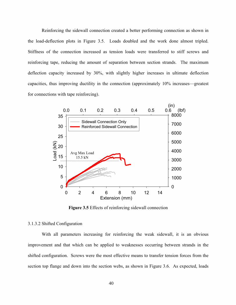
40
Reinforcing the sidewall connection created a better performing connection as shown in
the load-deflection plots in Figure 3.5. Loads doubled and the work done almost tripled.
Stiffness of the connection increased as tension loads were transferred to stiff screws and
reinforcing tape, reducing the amount of separation between section strands. The maximum
deflection capacity increased by 30%, with slightly higher increases in ultimate deflection
capacities, thus improving ductility in the connection (approximately 10% increases—greatest
for connections with tape reinforcing).
Extension (mm)0 2 4 6 8 10 12 14
Load
(kN
)
0
5
10
15
20
25
30
35Screw Connection Only Added Sidewall Perpendicular-to-Extrusion Reinforcement
(in)0.0 0.1 0.2 0.3 0.4 0.5 0.6 (lbf)
0
1000
2000
3000
4000
5000
6000
7000
8000Sidewall Connection OnlyReinforced Sidewall Connection
Figure 3.5 Effects of reinforcing sidewall connection
3.1.3.2 Shifted Configuration
With all parameters increasing for reinforcing the weak sidewall, it is an obvious
improvement and that which can be applied to weaknesses occurring between strands in the
shifted configuration. Screws were the most effective means to transfer tension forces from the
section top flange and down into the section webs, as shown in Figure 3.6. As expected, loads
Avg Max Load 15.5 kN
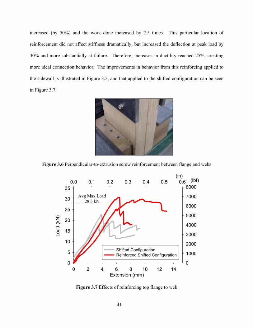
41
increased (by 50%) and the work done increased by 2.5 times. This particular location of
reinforcement did not affect stiffness dramatically, but increased the deflection at peak load by
30% and more substantially at failure. Therefore, increases in ductility reached 25%, creating
more ideal connection behavior. The improvements in behavior from this reinforcing applied to
the sidewall is illustrated in Figure 3.5, and that applied to the shifted configuration can be seen
in Figure 3.7.
Figure 3.6 Perpendicular-to-extrusion screw reinforcement between flange and webs
(in)0.0 0.1 0.2 0.3 0.4 0.5 0.6 (lbf)
0
1000
2000
3000
4000
5000
6000
7000
8000
Extension (mm)0 2 4 6 8 10 12 14
Load
(kN
)
0
5
10
15
20
25
30
35
Shifted Configuration Reinforced Shifted Configuration
Figure 3.7 Effects of reinforcing top flange to web
Avg Max Load 28.3 kN
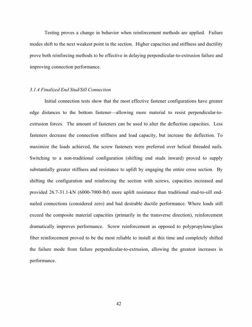
42
Testing proves a change in behavior when reinforcement methods are applied. Failure
modes shift to the next weakest point in the section. Higher capacities and stiffness and ductility
prove both reinforcing methods to be effective in delaying perpendicular-to-extrusion failure and
improving connection performance.
3.1.4 Finalized End Stud/Sill Connection
Initial connection tests show that the most effective fastener configurations have greater
edge distances to the bottom fastener—allowing more material to resist perpendicular-to-
extrusion forces. The amount of fasteners can be used to alter the deflection capacities. Less
fasteners decrease the connection stiffness and load capacity, but increase the deflection. To
maximize the loads achieved, the screw fasteners were preferred over helical threaded nails.
Switching to a non-traditional configuration (shifting end studs inward) proved to supply
substantially greater stiffness and resistance to uplift by engaging the entire cross section. By
shifting the configuration and reinforcing the section with screws, capacities increased and
provided 26.7-31.1-kN (6000-7000-lbf) more uplift resistance than traditional stud-to-sill end-
nailed connections (considered zero) and had desirable ductile performance. Where loads still
exceed the composite material capacities (primarily in the transverse direction), reinforcement
dramatically improves performance. Screw reinforcement as opposed to polypropylene/glass
fiber reinforcement proved to be the most reliable to install at this time and completely shifted
the failure mode from failure perpendicular-to-extrusion, allowing the greatest increases in
performance.
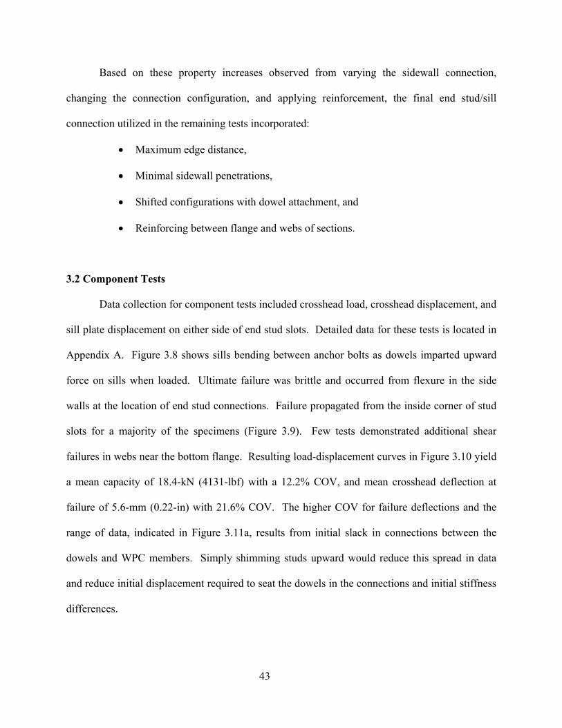
43
Based on these property increases observed from varying the sidewall connection,
changing the connection configuration, and applying reinforcement, the final end stud/sill
connection utilized in the remaining tests incorporated:
• Maximum edge distance,
• Minimal sidewall penetrations,
• Shifted configurations with dowel attachment, and
• Reinforcing between flange and webs of sections.
3.2 Component Tests
Data collection for component tests included crosshead load, crosshead displacement, and
sill plate displacement on either side of end stud slots. Detailed data for these tests is located in
Appendix A. Figure 3.8 shows sills bending between anchor bolts as dowels imparted upward
force on sills when loaded. Ultimate failure was brittle and occurred from flexure in the side
walls at the location of end stud connections. Failure propagated from the inside corner of stud
slots for a majority of the specimens (Figure 3.9). Few tests demonstrated additional shear
failures in webs near the bottom flange. Resulting load-displacement curves in Figure 3.10 yield
a mean capacity of 18.4-kN (4131-lbf) with a 12.2% COV, and mean crosshead deflection at
failure of 5.6-mm (0.22-in) with 21.6% COV. The higher COV for failure deflections and the
range of data, indicated in Figure 3.11a, results from initial slack in connections between the
dowels and WPC members. Simply shimming studs upward would reduce this spread in data
and reduce initial displacement required to seat the dowels in the connections and initial stiffness
differences.
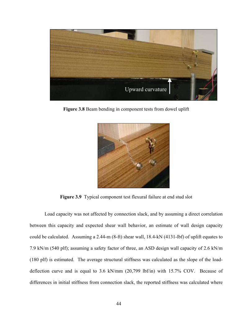
44
Figure 3.8 Beam bending in component tests from dowel uplift
Figure 3.9 Typical component test flexural failure at end stud slot
Load capacity was not affected by connection slack, and by assuming a direct correlation
between this capacity and expected shear wall behavior, an estimate of wall design capacity
could be calculated. Assuming a 2.44-m (8-ft) shear wall, 18.4-kN (4131-lbf) of uplift equates to
7.9 kN/m (540 plf); assuming a safety factor of three, an ASD design wall capacity of 2.6 kN/m
(180 plf) is estimated. The average structural stiffness was calculated as the slope of the load-
deflection curve and is equal to 3.6 kN/mm (20,799 lbf/in) with 15.7% COV. Because of
differences in initial stiffness from connection slack, the reported stiffness was calculated where
Upward curvature
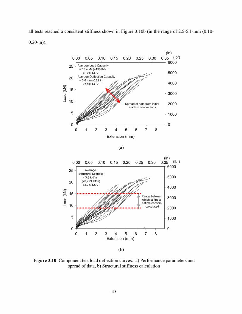
45
all tests reached a consistent stiffness shown in Figure 3.10b (in the range of 2.5-5.1-mm (0.10-
0.20-in)).
(in)0.00 0.05 0.10 0.15 0.20 0.25 0.30 0.35 (lbf)
0
1000
2000
3000
4000
5000
6000
Extension (mm)
0 1 2 3 4 5 6 7 8
Load
(kN
)
0
5
10
15
20
25
Spread of data from initial slack in connections
Average Load Capacity = 18.4 kN (4130 lbf) 12.2% COVAverage Deflection Capacity = 5.6 mm (0.22 in) 21.6% COV
(a)
(in)0.00 0.05 0.10 0.15 0.20 0.25 0.30 0.35 (lbf)
0
1000
2000
3000
4000
5000
6000
Extension (mm)0 1 2 3 4 5 6 7 8
Load
(kN
)
0
5
10
15
20
25 Average Structural Stiffness
= 3.6 kN/mm(20,799 lbf/in)15.7% COV
Range between which stiffness estimates were
calculated
(b)
Figure 3.10 Component test load deflection curves: a) Performance parameters and spread of data, b) Structural stiffness calculation
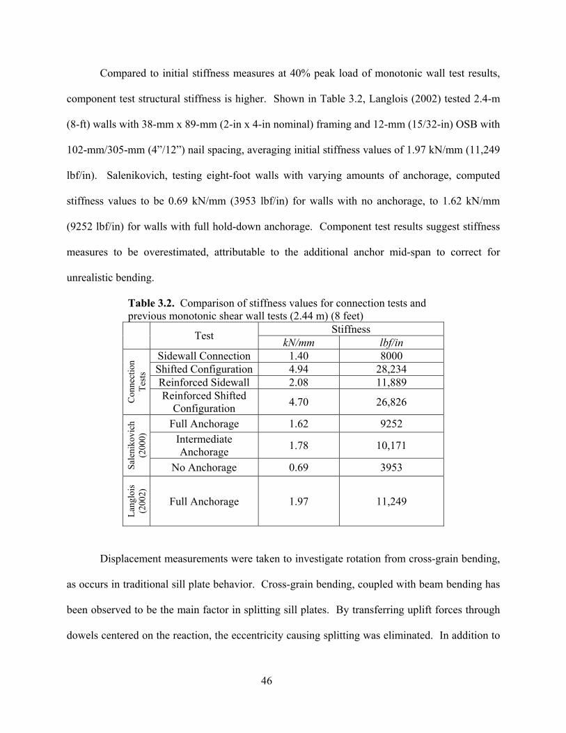
46
Compared to initial stiffness measures at 40% peak load of monotonic wall test results,
component test structural stiffness is higher. Shown in Table 3.2, Langlois (2002) tested 2.4-m
(8-ft) walls with 38-mm x 89-mm (2-in x 4-in nominal) framing and 12-mm (15/32-in) OSB with
102-mm/305-mm (4”/12”) nail spacing, averaging initial stiffness values of 1.97 kN/mm (11,249
lbf/in). Salenikovich, testing eight-foot walls with varying amounts of anchorage, computed
stiffness values to be 0.69 kN/mm (3953 lbf/in) for walls with no anchorage, to 1.62 kN/mm
(9252 lbf/in) for walls with full hold-down anchorage. Component test results suggest stiffness
measures to be overestimated, attributable to the additional anchor mid-span to correct for
unrealistic bending.
Table 3.2. Comparison of stiffness values for connection tests and previous monotonic shear wall tests (2.44 m) (8 feet)
Stiffness Test kN/mm lbf/in Sidewall Connection 1.40 8000 Shifted Configuration 4.94 28,234 Reinforced Sidewall 2.08 11,889
Con
nect
ion
Test
s
Reinforced Shifted Configuration 4.70 26,826
Full Anchorage 1.62 9252 Intermediate Anchorage 1.78 10,171
Sale
niko
vich
(2
000)
No Anchorage 0.69 3953
Lang
lois
(2
002)
Full Anchorage 1.97 11,249
Displacement measurements were taken to investigate rotation from cross-grain bending,
as occurs in traditional sill plate behavior. Cross-grain bending, coupled with beam bending has
been observed to be the main factor in splitting sill plates. By transferring uplift forces through
dowels centered on the reaction, the eccentricity causing splitting was eliminated. In addition to
47
eliminating cross-grain bending, locating anchor bolts closer to maximum uplift forces reduced
cantilever behavior and resulting wall deflection. This suggests ideal anchorage conditions
would be continuous along the length of sill plates—reducing upward deflection and essentially
reducing flexural splitting.
3.3 Connection and Component Test Summary
WPC sections are durable and have the ability to be extruded in unique shapes and
machined for specific applications. For the sill plate application, the following conclusions have
been made resulting from preliminary section investigation:
• Fasteners between end studs and sills should provide the maximum edge distance,
minimum number of penetrations, and distribution of load to the entire sill cross section
to provide the optimal load and deflection capacities.
• Altering the traditional end stud-to-sill connection configuration provides substantial
improved uplift capacity, decreased beam bending of sill ends, and eliminates cross-grain
bending inherent in traditional sill plates. This shift in configuration includes moving the
end stud in from the sill end, anchoring the sill 32-mm (1-1/4-in) from the end, and
installing dowels through PP10 hollow cavities and through end studs.
• Stranding during processing creates weaknesses in the transverse direction. Methods of
bonding reinforcement to the surface perpendicular to the failure plane, or installing
screws into the thickness, perpendicular and through the failure plane, are efficient ways
of improving the performance by avoiding early failure between strands.
48
CHAPTER 4 SHEAR WALL PERFORMANCE
4.1 Test Parameters
Test analysis was based on performance parameters outlined in ASTM E2126-02a, and
detailed monotonic and cyclic test results can be found in Appendix B. Monotonic test response
curves consist of load versus wall racking deflection, from zero deflection up until load drops to
20% of peak capacity. Cyclic test results are reported in the form of envelope response curves,
developed by drawing a line through points of maximum loads in each cycle of the hysteresis
curves. Wall deflections were measured along the top plate, in line with the center stud, in order
to allow the actual horizontal displacement to be obtained without including displacements
caused by uplift at walls’ ends. Deflections for all response curves have also been adjusted to
account for fixture slip. Due to reversed loading, positive and negative envelopes were
developed for each test, and then the absolute values of the curves were averaged to develop a
single quadrant envelope for each wall test, from which performance parameters were computed.
For multiple tests within a test group, average group values were computed from average
individual test parameters. Both monotonic response curves and calculations based on hysteresis
loops included cycles up to failure loads based on average response curve parameters.
In developing complete hysteresis curves, data collected from wall displacement and load
channels was edited. Positive hysteresis loops represent the response of the wall corresponding
to the first peak of the primary cycle; negative hysteresis loops correspond to the second peak of
the primary cycle. This becomes important as damage accumulation of the wall from the 1st
primary peak affects performance in the reverse direction primary peak. Due to difficulties with
digital control of the MTS 407 controller, actuator direction in the displacement-time history
reversed during testing. Beginning loading sequences had first primary cycles in the positive
49
actuator direction, and shifted partway to be in the negative direction. To account for this
switch, load-deflection data was multiplied by a negative one from the actuator reversal point to
keep the positive and negative hysteresis loops consistent with the defined sign convention.
Detailed time histories can be found in Appendix B.
Shear strength, v, is defined as the peak load, Ppeak, divided by the wall length, L, and is
expressed mathematically as:
/peak Lv P= (4.1)
where Ppeak is taken as the absolute maximum load. Failure loads and displacements (ultimate
capacities) are by definition 80% of the peak load and occur on the post-peak portion of the
response curve. Loads and displacements at 40% peak capacity are calculated and used in
determining the elastic shear stiffness, ke (ASTM 2126-02a).
0.400.40 / peake peak Pk P= ∆ (4.2)
Cyclic elastic shear stiffness is equal to the slope of the elastic portion of EEEP curves and
provides an estimate of wall stiffness when subjected to multiple loading cycles at low to
moderate amplitudes (Salenikovich, 2000).
Secant shear moduli may be determined at either 40% peak load or at peak load by taking
the quotient of the load, P, and displacement, ∆, and multiplying by the wall’s height-to-width
ratio, H/L (ASTM 2126-02a). The secant shear moduli, G’, is represented as:
' ( / )*( / )G P H L= ∆ (4.3)
where, P is the load of interest, ∆ is the corresponding displacement, H is wall height, and L is
wall length. Height-to-width ratios for tests in this study were all 1:1.

50
Further performance characterization may be completed after constructing a curve
representing an ideal perfectly elastic-plastic wall behavior—an equivalent energy elastic-plastic
curve (EEEP). The curve is plotted such that the area enclosed equals the area under the
envelope response curve. For monotonic test results, EEEP curves allow direct comparison of
wall performance on an energy basis. For cyclic tests, the comparison is relative as the EEEP
curve represents area under envelope curves, rather than total energy dissipated when summing
the area under each overlapping cycle loop. Area enclosed under cyclic hysteresis curves must
be calculated separately to truly compare energy dissipation.
EEEP curves consist of an elastic region that proceeds at a constant slope until yielding
occurs, that is followed by a horizontal plastic region that is maintained until failure. The elastic
portion goes through the origin and point of 40% peak load, at a slope equal to the elastic shear
stiffness. The intersection point between elastic and plastic portions of curves is the point of
yield and is positioned where the area under the EEEP curve is equal to the area under the
response curve up to failure. The yield load is expressed as (Heine, 1997):
2 2 /
1/failure failure e
yielde
A kPk
−∆ ± ∆ −=−
(4.4)
where A is area under response curve up to the point of failure.
Ductility calculations provide a measure of walls’ ability to withstand inelastic deflection
during earthquake loading. In design, more ductile performance is credited with lower seismic
forces to resist, as deformation in the inelastic region provides significantly more energy
dissipation (Breyer et al, 1999). This reduction in base shear forces is accounted for in the IBC
response modification factor, R (ICBO, 2000b).
51
In order to fully characterize a wall’s inelastic response over the entire load range, three
ductility ratios will be calculated for each wall type. The displacement measures to calculate
these parameters are taken from the EEEP curve as light-frame shear walls are not perfectly-
plastic in their behavior. These parameters must be considered in addition to maximum and
ultimate displacements achieved, as the yield load and displacement affects ductility. The
ductility ratio, D, is expressed:
/peak yieldD = ∆ ∆ (4.5)
The ultimate ductility ratio, Du, provides a measure for comparison in the response of a wall
between yield and failure. This value illustrates the amount of displacement available after
yielding for load transfer to adjacent structural components (Salenikovich, 2000):
/u failure yieldD = ∆ ∆ (4.6)
Lastly, the toughness index is calculated as a measure of displacement capacity remaining after
reaching peak capacity:
/f failure peakD = ∆ ∆ (4.7)
4.2 Monotonic Test Results
Four monotonic walls, representing each wall type presented in Figure 4.1, were tested to
develop reference displacements for cyclic tests. Racking displacement readings were taken at
the top of wall, opposite load application. Detailed test photos and a summary of performance
parameters are located in Appendix B. Performance parameters, such as maximum absolute
load, failure load, 40% peak load, yield load, associated displacements, and energy dissipation,
are reported. Knowing these factors, an equivalent energy elastic-plastic (EEEP) curve was
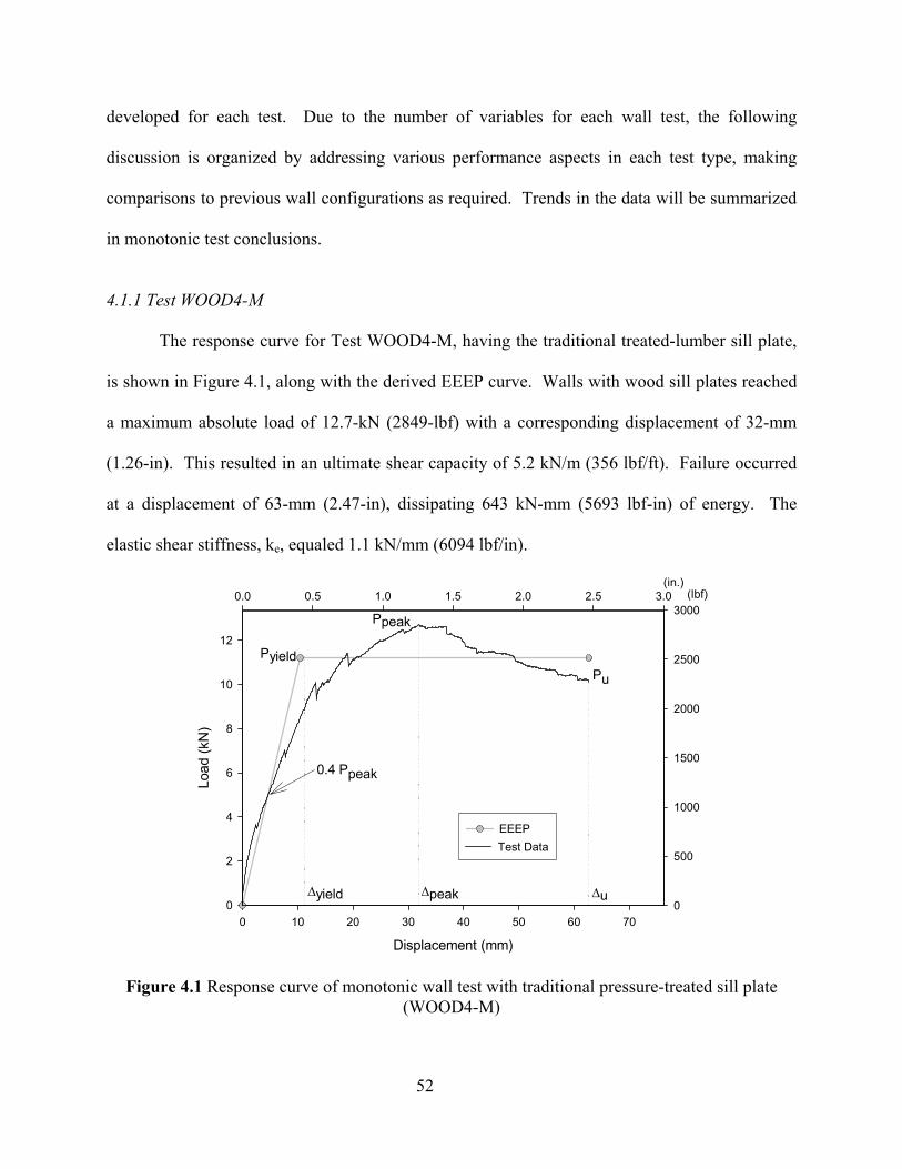
52
developed for each test. Due to the number of variables for each wall test, the following
discussion is organized by addressing various performance aspects in each test type, making
comparisons to previous wall configurations as required. Trends in the data will be summarized
in monotonic test conclusions.
4.1.1 Test WOOD4-M
The response curve for Test WOOD4-M, having the traditional treated-lumber sill plate,
is shown in Figure 4.1, along with the derived EEEP curve. Walls with wood sill plates reached
a maximum absolute load of 12.7-kN (2849-lbf) with a corresponding displacement of 32-mm
(1.26-in). This resulted in an ultimate shear capacity of 5.2 kN/m (356 lbf/ft). Failure occurred
at a displacement of 63-mm (2.47-in), dissipating 643 kN-mm (5693 lbf-in) of energy. The
elastic shear stiffness, ke, equaled 1.1 kN/mm (6094 lbf/in).
Displacement (mm)
0 10 20 30 40 50 60 70
Load
(kN
)
0
2
4
6
8
10
12
EEEP
(in.)0.0 0.5 1.0 1.5 2.0 2.5 3.0 (lbf)
0
500
1000
1500
2000
2500
3000
Test Data
PyieldPu
Ppeak
0.4 Ppeak
∆yield ∆u∆peak
Figure 4.1 Response curve of monotonic wall test with traditional pressure-treated sill plate (WOOD4-M)
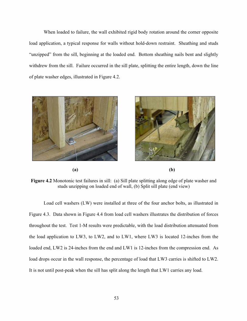
53
When loaded to failure, the wall exhibited rigid body rotation around the corner opposite
load application, a typical response for walls without hold-down restraint. Sheathing and studs
“unzipped” from the sill, beginning at the loaded end. Bottom sheathing nails bent and slightly
withdrew from the sill. Failure occurred in the sill plate, splitting the entire length, down the line
of plate washer edges, illustrated in Figure 4.2.
(a)
(b)
Figure 4.2 Monotonic test failures in sill: (a) Sill plate splitting along edge of plate washer and studs unzipping on loaded end of wall, (b) Split sill plate (end view)
Load cell washers (LW) were installed at three of the four anchor bolts, as illustrated in
Figure 4.3. Data shown in Figure 4.4 from load cell washers illustrates the distribution of forces
throughout the test. Test 1-M results were predictable, with the load distribution attenuated from
the load application to LW3, to LW2, and to LW1, where LW3 is located 12-inches from the
loaded end, LW2 is 24-inches from the end and LW1 is 12-inches from the compression end. As
load drops occur in the wall response, the percentage of load that LW3 carries is shifted to LW2.
It is not until post-peak when the sill has split along the length that LW1 carries any load.
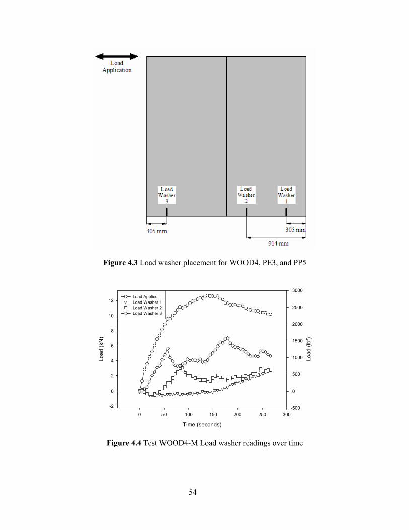
54
Figure 4.3 Load washer placement for WOOD4, PE3, and PP5
Time (seconds)
0 50 100 150 200 250 300
Load
(kN
)
-2
0
2
4
6
8
10
12Load AppliedLoad Washer 1Load Washer 2Load Washer 3
Load
(lbf
)
-500
0
500
1000
1500
2000
2500
3000Load AppliedLoad Washer 1Load Washer 2Load Washer 3
Figure 4.4 Test WOOD4-M Load washer readings over time
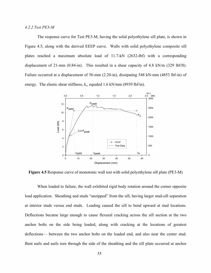
55
4.2.2 Test PE3-M
The response curve for Test PE3-M, having the solid polyethylene sill plate, is shown in
Figure 4.5, along with the derived EEEP curve. Walls with solid polyethylene composite sill
plates reached a maximum absolute load of 11.7-kN (2632-lbf) with a corresponding
displacement of 21-mm (0.84-in). This resulted in a shear capacity of 4.8 kN/m (329 lbf/ft).
Failure occurred at a displacement of 56-mm (2.20-in), dissipating 548 kN-mm (4853 lbf-in) of
energy. The elastic shear stiffness, ke, equaled 1.6 kN/mm (8939 lbf/in).
Displacement (mm)
0 10 20 30 40 50 60
Load
(kN
)
0
2
4
6
8
10
12
EEEP
(in.)0.0 0.5 1.0 1.5 2.0 2.5 (lbf)
0
500
1000
1500
2000
2500
3000
Test Data
Pyield
Pu
Ppeak
0.4 Ppeak
∆yield ∆u∆peak
Figure 4.5 Response curve of monotonic wall test with solid polyethylene sill plate (PE3-M)
When loaded to failure, the wall exhibited rigid body rotation around the corner opposite
load application. Sheathing and studs “unzipped” from the sill, having larger stud-sill separation
at interior studs versus end studs. Loading caused the sill to bend upward at stud locations.
Deflections became large enough to cause flexural cracking across the sill section at the two
anchor bolts on the side being loaded, along with cracking at the locations of greatest
deflections— between the two anchor bolts on the loaded end, and also near the center stud.
Bent nails and nails torn through the side of the sheathing and the sill plate occurred at anchor
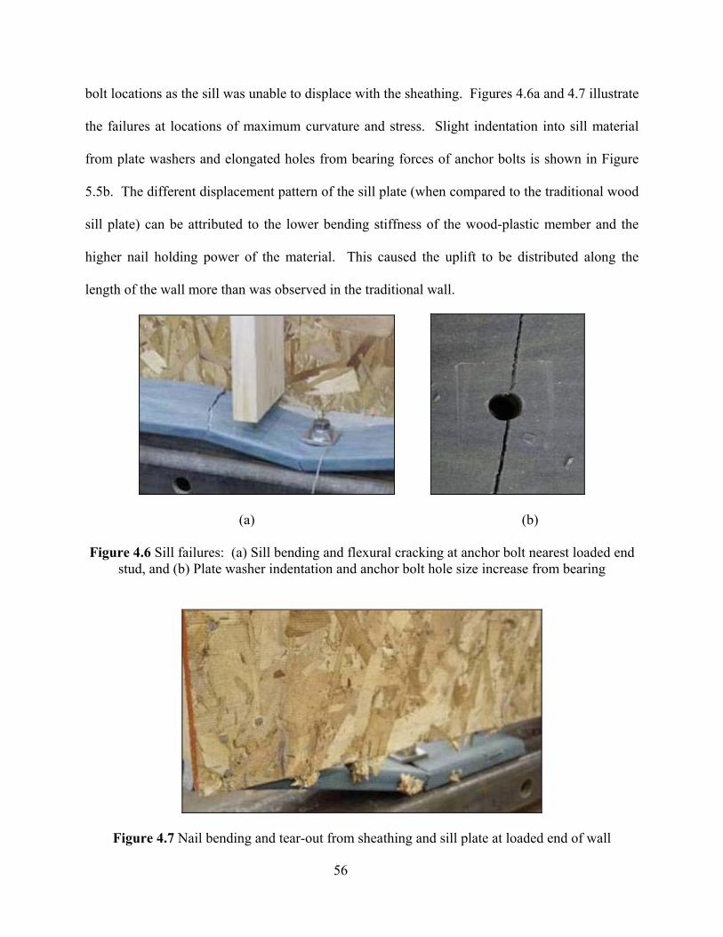
56
bolt locations as the sill was unable to displace with the sheathing. Figures 4.6a and 4.7 illustrate
the failures at locations of maximum curvature and stress. Slight indentation into sill material
from plate washers and elongated holes from bearing forces of anchor bolts is shown in Figure
5.5b. The different displacement pattern of the sill plate (when compared to the traditional wood
sill plate) can be attributed to the lower bending stiffness of the wood-plastic member and the
higher nail holding power of the material. This caused the uplift to be distributed along the
length of the wall more than was observed in the traditional wall.
(a)
(b)
Figure 4.6 Sill failures: (a) Sill bending and flexural cracking at anchor bolt nearest loaded end stud, and (b) Plate washer indentation and anchor bolt hole size increase from bearing
Figure 4.7 Nail bending and tear-out from sheathing and sill plate at loaded end of wall
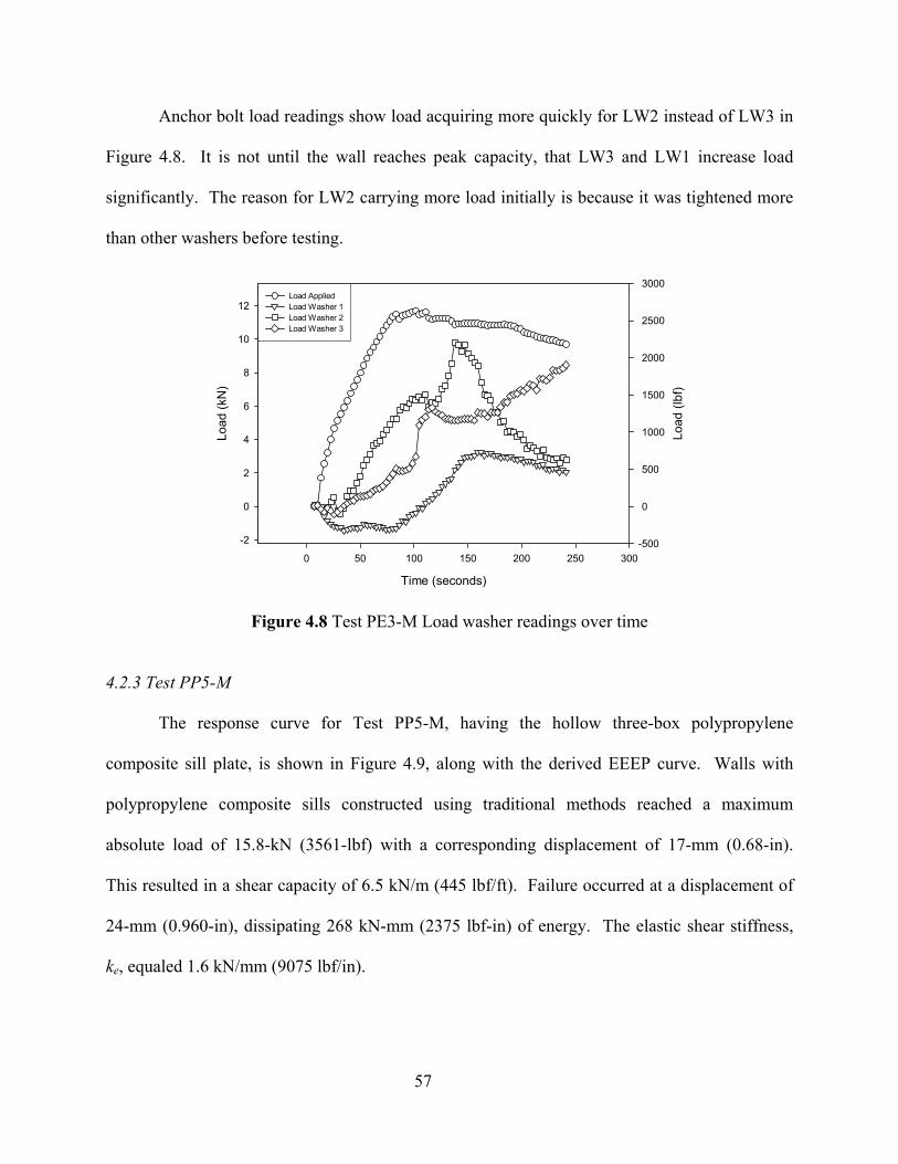
57
Anchor bolt load readings show load acquiring more quickly for LW2 instead of LW3 in
Figure 4.8. It is not until the wall reaches peak capacity, that LW3 and LW1 increase load
significantly. The reason for LW2 carrying more load initially is because it was tightened more
than other washers before testing.
Time (seconds)
0 50 100 150 200 250 300
Load
(kN
)
-2
0
2
4
6
8
10
12Load AppliedLoad Washer 1Load Washer 2Load Washer 3
Load
(lbf
)
-500
0
500
1000
1500
2000
2500
3000Load AppliedLoad Washer 1Load Washer 2Load Washer 3
Figure 4.8 Test PE3-M Load washer readings over time
4.2.3 Test PP5-M
The response curve for Test PP5-M, having the hollow three-box polypropylene
composite sill plate, is shown in Figure 4.9, along with the derived EEEP curve. Walls with
polypropylene composite sills constructed using traditional methods reached a maximum
absolute load of 15.8-kN (3561-lbf) with a corresponding displacement of 17-mm (0.68-in).
This resulted in a shear capacity of 6.5 kN/m (445 lbf/ft). Failure occurred at a displacement of
24-mm (0.960-in), dissipating 268 kN-mm (2375 lbf-in) of energy. The elastic shear stiffness,
ke, equaled 1.6 kN/mm (9075 lbf/in).

58
Displacement (mm)
0 4 8 12 16 20 24 28
Load
(kN
)
0
2
4
6
8
10
12
14
16
EEEP
(in.)0.0 0.2 0.4 0.6 0.8 1.0 1.2 (lbf)
0
1000
2000
3000
4000
Test Data
PyieldPu
Ppeak
0.4 Ppeak
∆yield ∆u∆peak
Figure 4.9 Response curve of monotonic wall test with hollow polypropylene three-box sill plate (PP5-M)
When loaded to failure, the wall exhibited rigid body rotation around the corner opposite
load application. Sheathing and studs “unzipped” from the sill, and the sill rotated in the
perpendicular-to-extrusion direction—this behavior is illustrated in Figure 4.10a. Failure was
brittle, occurring in flexure at the location of the anchor bolt. The brittle failure occurred when
the outside box, resisting the largest load, split along strands formed during processing. The split
on the top surface paralleled the plate washer edges, and the side split occurred at the intersection
of the side web and bottom flange, as shown in Figures 4.10b and 4.11. The failure was due to
the inherent weakness of this material in the perpendicular-to-extrusion direction. Sheathing
nails appeared to have withdrawn along the bottom edge at locations of greatest flexure—at the
anchor bolt on the loaded end. Indentation from plate bearing, as occurred in the polyethylene
composite, was not apparent for this polypropylene section.
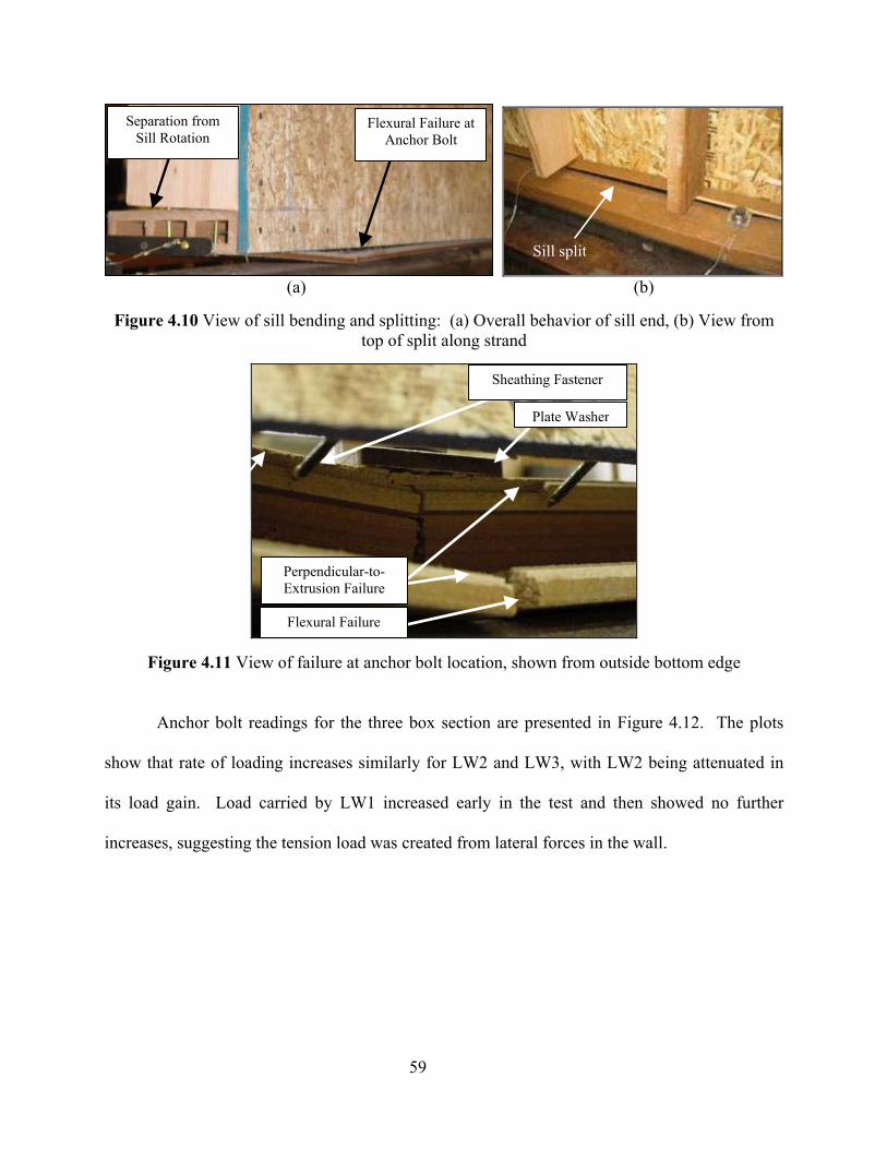
59
(a) (b)
Figure 4.10 View of sill bending and splitting: (a) Overall behavior of sill end, (b) View from
top of split along strand
Figure 4.11 View of failure at anchor bolt location, shown from outside bottom edge
Anchor bolt readings for the three box section are presented in Figure 4.12. The plots
show that rate of loading increases similarly for LW2 and LW3, with LW2 being attenuated in
its load gain. Load carried by LW1 increased early in the test and then showed no further
increases, suggesting the tension load was created from lateral forces in the wall.
Separation from Sill Rotation
Flexural Failure at Anchor Bolt
Sill split
Flexural Failure
Perpendicular-to-Extrusion Failure
Plate Washer
Sheathing Fastener
Splitting along strand
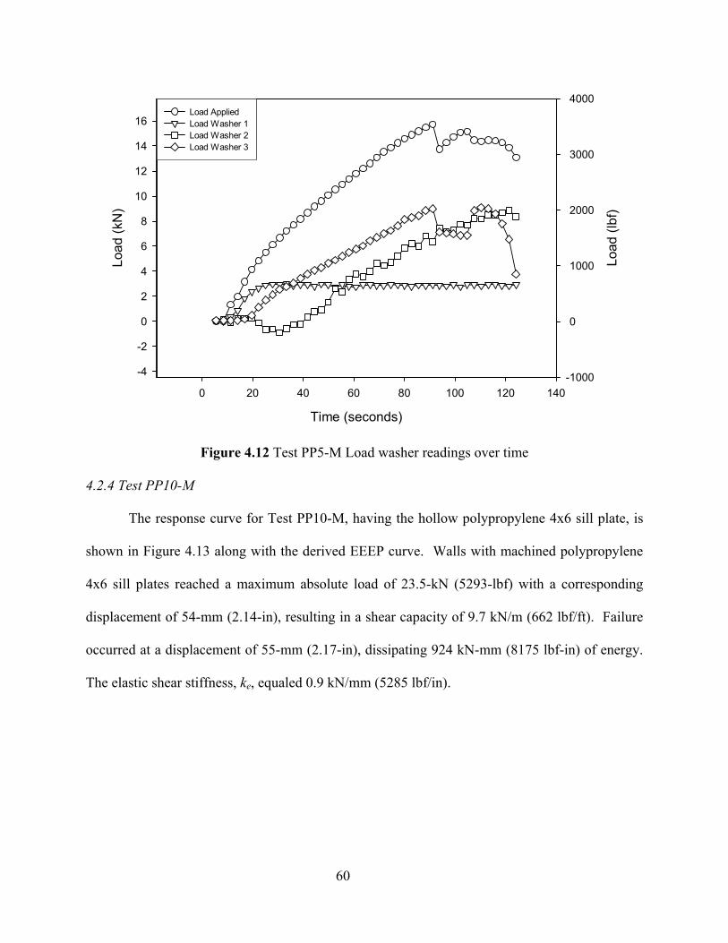
60
Time (seconds)
0 20 40 60 80 100 120 140
Load
(kN
)
-4
-2
0
2
4
6
8
10
12
14
16Load AppliedLoad Washer 1Load Washer 2Load Washer 3
Load
(lbf
)
-1000
0
1000
2000
3000
4000Load AppliedLoad Washer 1Load Washer 2Load Washer 3
Figure 4.12 Test PP5-M Load washer readings over time 4.2.4 Test PP10-M
The response curve for Test PP10-M, having the hollow polypropylene 4x6 sill plate, is
shown in Figure 4.13 along with the derived EEEP curve. Walls with machined polypropylene
4x6 sill plates reached a maximum absolute load of 23.5-kN (5293-lbf) with a corresponding
displacement of 54-mm (2.14-in), resulting in a shear capacity of 9.7 kN/m (662 lbf/ft). Failure
occurred at a displacement of 55-mm (2.17-in), dissipating 924 kN-mm (8175 lbf-in) of energy.
The elastic shear stiffness, ke, equaled 0.9 kN/mm (5285 lbf/in).
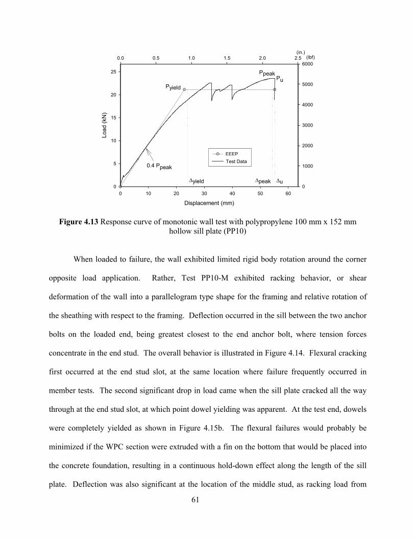
61
Displacement (mm)
0 10 20 30 40 50 60
Load
(kN
)
0
5
10
15
20
25
EEEP
(in.)0.0 0.5 1.0 1.5 2.0 2.5 (lbf)
0
1000
2000
3000
4000
5000
6000
Test Data
Pyield
PuPpeak
0.4 Ppeak
∆yield ∆u∆peak
Figure 4.13 Response curve of monotonic wall test with polypropylene 100 mm x 152 mm hollow sill plate (PP10)
When loaded to failure, the wall exhibited limited rigid body rotation around the corner
opposite load application. Rather, Test PP10-M exhibited racking behavior, or shear
deformation of the wall into a parallelogram type shape for the framing and relative rotation of
the sheathing with respect to the framing. Deflection occurred in the sill between the two anchor
bolts on the loaded end, being greatest closest to the end anchor bolt, where tension forces
concentrate in the end stud. The overall behavior is illustrated in Figure 4.14. Flexural cracking
first occurred at the end stud slot, at the same location where failure frequently occurred in
member tests. The second significant drop in load came when the sill plate cracked all the way
through at the end stud slot, at which point dowel yielding was apparent. At the test end, dowels
were completely yielded as shown in Figure 4.15b. The flexural failures would probably be
minimized if the WPC section were extruded with a fin on the bottom that would be placed into
the concrete foundation, resulting in a continuous hold-down effect along the length of the sill
plate. Deflection was also significant at the location of the middle stud, as racking load from
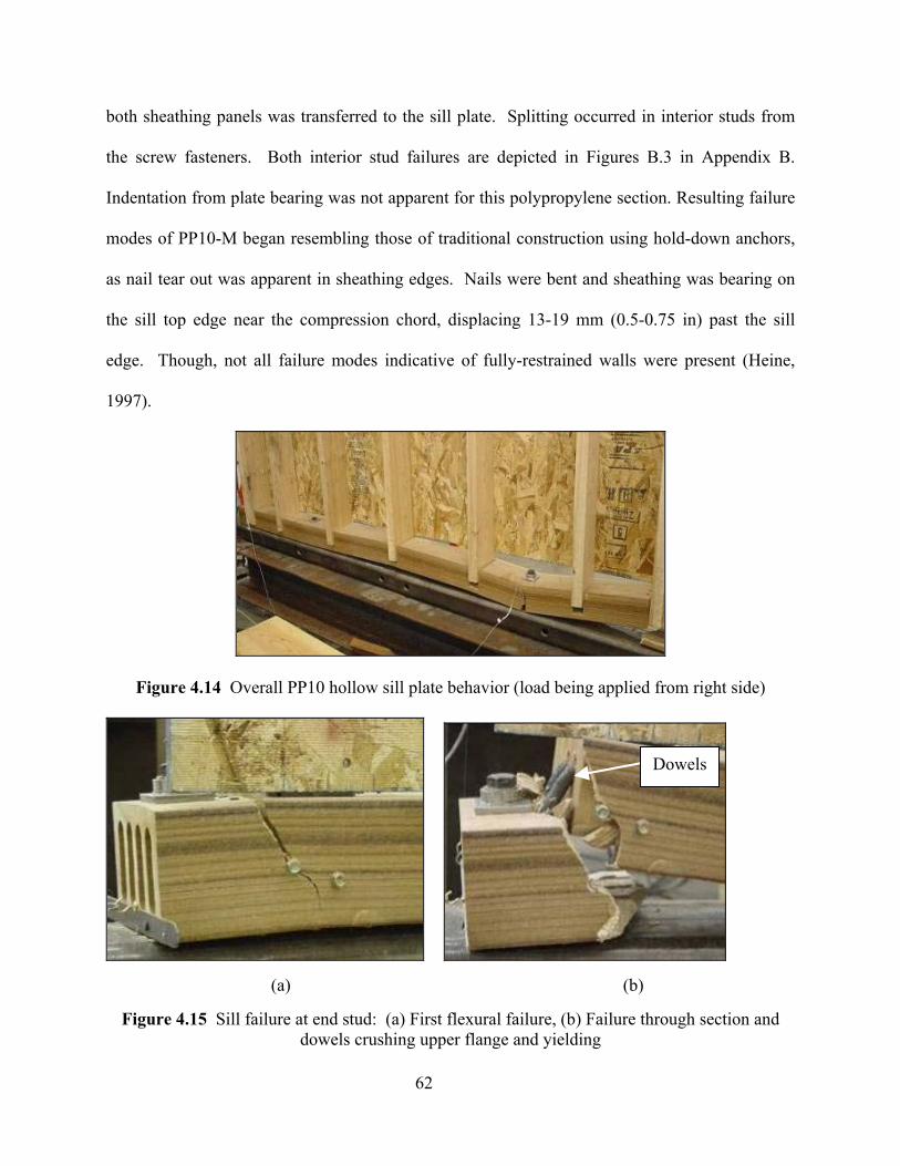
62
both sheathing panels was transferred to the sill plate. Splitting occurred in interior studs from
the screw fasteners. Both interior stud failures are depicted in Figures B.3 in Appendix B.
Indentation from plate bearing was not apparent for this polypropylene section. Resulting failure
modes of PP10-M began resembling those of traditional construction using hold-down anchors,
as nail tear out was apparent in sheathing edges. Nails were bent and sheathing was bearing on
the sill top edge near the compression chord, displacing 13-19 mm (0.5-0.75 in) past the sill
edge. Though, not all failure modes indicative of fully-restrained walls were present (Heine,
1997).
Figure 4.14 Overall PP10 hollow sill plate behavior (load being applied from right side)
(a)
(b)
Figure 4.15 Sill failure at end stud: (a) First flexural failure, (b) Failure through section and dowels crushing upper flange and yielding
Dowels
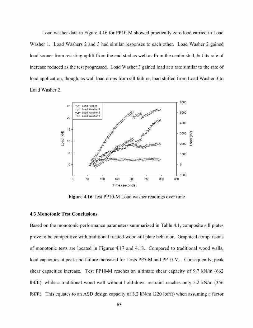
63
Load washer data in Figure 4.16 for PP10-M showed practically zero load carried in Load
Washer 1. Load Washers 2 and 3 had similar responses to each other. Load Washer 2 gained
load sooner from resisting uplift from the end stud as well as from the center stud, but its rate of
increase reduced as the test progressed. Load Washer 3 gained load at a rate similar to the rate of
load application, though, as wall load drops from sill failure, load shifted from Load Washer 3 to
Load Washer 2.
Time (seconds)
0 50 100 150 200 250 300 350
Load
(kN
)
0
5
10
15
20
25 Load AppliedLoad Washer 1Load Washer 2Load Washer 3
Load
(lbf
)
-1000
0
1000
2000
3000
4000
5000
6000Load AppliedLoad Washer 1Load Washer 2Load Washer 3
Figure 4.16 Test PP10-M Load washer readings over time
4.3 Monotonic Test Conclusions
Based on the monotonic performance parameters summarized in Table 4.1, composite sill plates
prove to be competitive with traditional treated-wood sill plate behavior. Graphical comparisons
of monotonic tests are located in Figures 4.17 and 4.18. Compared to traditional wood walls,
load capacities at peak and failure increased for Tests PP5-M and PP10-M. Consequently, peak
shear capacities increase. Test PP10-M reaches an ultimate shear capacity of 9.7 kN/m (662
lbf/ft), while a traditional wood wall without hold-down restraint reaches only 5.2 kN/m (356
lbf/ft). This equates to an ASD design capacity of 3.2 kN/m (220 lbf/ft) when assuming a factor
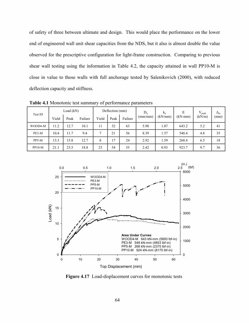
64
of safety of three between ultimate and design. This would place the performance on the lower
end of engineered wall unit shear capacities from the NDS, but it also is almost double the value
observed for the prescriptive configuration for light-frame construction. Comparing to previous
shear wall testing using the information in Table 4.2, the capacity attained in wall PP10-M is
close in value to those walls with full anchorage tested by Salenikovich (2000), with reduced
deflection capacity and stiffness.
Top Displacement (mm)
0 10 20 30 40 50 60
Load
(kN
)
0
5
10
15
20
25 1-M2-M3-M4-M
(in.)0.0 0.5 1.0 1.5 2.0 2.5 (lbf)
0
1000
2000
3000
4000
5000
6000WOOD4-MPE3-MPP5-MPP10-M
Area Under CurvesWOOD4-M 643 kN-mm (5693 lbf-in)PE3-M 548 kN-mm (4853 lbf-in)PP5-M 268 kN-mm (2375 lbf-in)PP10-M 924 kN-mm (8175 lbf-in)
Figure 4.17 Load-displacement curves for monotonic tests
Table 4.1 Monotonic test summary of performance parameters Load (kN) Deflection (mm)
Test ID Yield Peak Failure Yield Peak Failure
Du (mm/mm)
ke (kN/mm)
E (kN-mm)
Vpeak (kN/m)
∆re (mm)
WOOD4-M 11.2 12.7 10.1 11 32 63 5.98 1.07 643.2 5.2 41
PE3-M 10.4 11.7 9.4 7 21 56 8.39 1.57 548.4 4.8 35
PP5-M 13.3 15.8 12.7 8 17 24 2.92 1.59 268.4 6.5 18
PP10-M 21.1 23.5 18.8 23 54 55 2.42 0.93 923.7 9.7 36
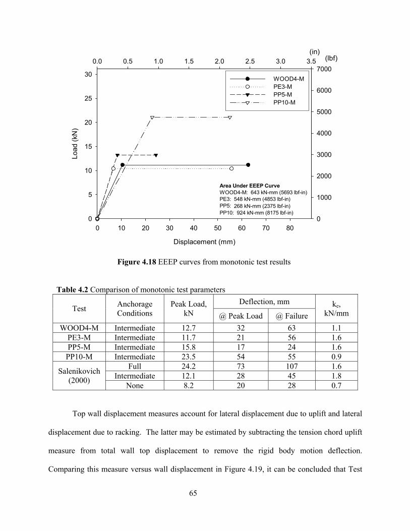
65
Displacement (mm)
0 10 20 30 40 50 60 70 80
Load
(kN
)
0
5
10
15
20
25
30
1-M2-M3-M4-M
(in)0.0 0.5 1.0 1.5 2.0 2.5 3.0 3.5 (lbf)
0
1000
2000
3000
4000
5000
6000
7000WOOD4-MPE3-MPP5-MPP10-M
Area Under EEEP CurveWOOD4-M: 643 kN-mm (5693 lbf-in)PE3: 548 kN-mm (4853 lbf-in)PP5: 268 kN-mm (2375 lbf-in)PP10: 924 kN-mm (8175 lbf-in)
Figure 4.18 EEEP curves from monotonic test results
Table 4.2 Comparison of monotonic test parameters Deflection, mm
Test Anchorage Conditions
Peak Load, kN @ Peak Load @ Failure
ke, kN/mm
WOOD4-M Intermediate 12.7 32 63 1.1 PE3-M Intermediate 11.7 21 56 1.6 PP5-M Intermediate 15.8 17 24 1.6 PP10-M Intermediate 23.5 54 55 0.9
Full 24.2 73 107 1.6 Intermediate 12.1 28 45 1.8 Salenikovich
(2000) None 8.2 20 28 0.7
Top wall displacement measures account for lateral displacement due to uplift and lateral
displacement due to racking. The latter may be estimated by subtracting the tension chord uplift
measure from total wall top displacement to remove the rigid body motion deflection.
Comparing this measure versus wall displacement in Figure 4.19, it can be concluded that Test

66
PP10-M exhibits substantially more racking movement, which increases at a linear rate. This is
consistent with damage observations unique to Test PP10-M, having more sheathing fasteners
yielded and visible sheathing movement relative to studs. The majority of top wall displacement
for Tests WOOD4-M, PE3-M, and PP5-M are contributed to uplift of wall ends from rigid body
rotation. The deformation pattern of Specimen PP10-M is more desirable as it results in a more
distributed damage pattern by activating more of the structure and increases the damping effects
of the system.
Wall Displacement (mm)
0 10 20 30 40 50 60
Dis
plac
emen
t Due
to R
acki
ng (m
m)
-4
0
4
8
12
16
20
24
28
32
36
40
1-M2-M3-M4-M
(in)0.0 0.5 1.0 1.5 2.0 2.5 (in)
-0.2
0.0
0.2
0.4
0.6
0.8
1.0
1.2
1.4
1.6
WOOD4-MPE3-MPP5-MPP10-M
Figure 4.19 Racking displacement of walls in monotonic tests
After analyzing the data provided in Table 4.1 and the failure modes observed, the
following conclusions can be inferred:
• The 1x solid polyethylene sill plate (PE3) proved feasible as an equal replacement for
traditional wood sill plate, achieving the highest ductility of all wall configurations.
Loads were comparable, with energy dissipation decreasing by 17%, and deflection is
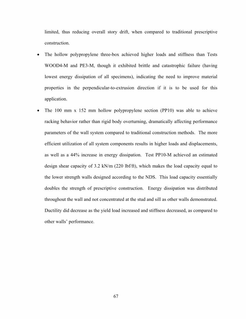
67
limited, thus reducing overall story drift, when compared to traditional prescriptive
construction.
• The hollow polypropylene three-box achieved higher loads and stiffness than Tests
WOOD4-M and PE3-M, though it exhibited brittle and catastrophic failure (having
lowest energy dissipation of all specimens), indicating the need to improve material
properties in the perpendicular-to-extrusion direction if it is to be used for this
application.
• The 100 mm x 152 mm hollow polypropylene section (PP10) was able to achieve
racking behavior rather than rigid body overturning, dramatically affecting performance
parameters of the wall system compared to traditional construction methods. The more
efficient utilization of all system components results in higher loads and displacements,
as well as a 44% increase in energy dissipation. Test PP10-M achieved an estimated
design shear capacity of 3.2 kN/m (220 lbf/ft), which makes the load capacity equal to
the lower strength walls designed according to the NDS. This load capacity essentially
doubles the strength of prescriptive construction. Energy dissipation was distributed
throughout the wall and not concentrated at the stud and sill as other walls demonstrated.
Ductility did decrease as the yield load increased and stiffness decreased, as compared to
other walls’ performance.
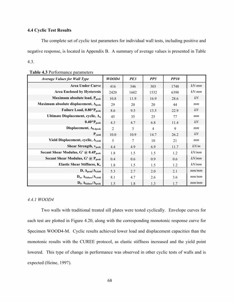
68
4.4 Cyclic Test Results
The complete set of cyclic test parameters for individual wall tests, including positive and
negative response, is located in Appendix B. A summary of average values is presented in Table
4.3.
Table 4.3 Performance parameters Average Values for Wall Type WOOD4 PE3 PP5 PP10
Area Under Curve 416 346 303 1748 kN-mm Area Enclosed by Hysteresis 2420 1602 1532 6398 kN-mm
Maximum absolute load, Ppeak 10.8 11.9 16.9 28.6 kN Maximum absolute displacement, ∆peak 29 20 20 44 mm
Failure Load, 0.80*Ppeak 8.6 9.5 13.5 22.9 kN Ultimate Displacement, cyclic, ∆u 45 35 25 77 mm
0.40*Ppeak 4.3 4.7 6.8 11.4 kN Displacement, ∆0.4peak 2 3 4 9 mm
Pyield 10.0 10.9 14.7 26.2 kN Yield Displacement, cyclic, ∆yield 5 7 10 21 mm
Shear Strength, vpeak 4.4 4.9 6.9 11.7 kN/m Secant Shear Modulus, G' @ 0.4Ppeak 1.8 1.5 1.5 1.2 kN/mm
Secant Shear Modulus, G' @ Ppeak 0.4 0.6 0.9 0.6 kN/mm Elastic Shear Stiffness, Ke 1.8 1.5 1.5 1.2 kN/mm
D, ∆peak/∆yield 5.3 2.7 2.0 2.1 mm/mm Du, ∆failure/∆yield 8.1 4.7 2.6 3.6 mm/mm Df, ∆failure/∆peak 1.5 1.8 1.3 1.7 mm/mm
4.4.1 WOOD4
Two walls with traditional treated sill plates were tested cyclically. Envelope curves for
each test are plotted in Figure 4.20, along with the corresponding monotonic response curve for
Specimen WOOD4-M. Cyclic results achieved lower load and displacement capacities than the
monotonic results with the CUREE protocol, as elastic stiffness increased and the yield point
lowered. This type of change in performance was observed in other cyclic tests of walls and is
expected (Heine, 1997).
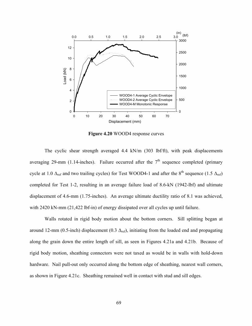
69
Displacement (mm)0 10 20 30 40 50 60 70
Load
(kN
)
0
2
4
6
8
10
12
1-1 Average Cyclic Envelope1-2 Average Cyclic Envelope1-M Monotonic Response
(in)0.0 0.5 1.0 1.5 2.0 2.5 3.0
0
500
1000
1500
2000
2500
3000
WOOD4-1 Average Cyclic EnvelopeWOOD4-2 Average Cyclic EnvelopeWOOD4-M Monotonic Response
(lbf)
Figure 4.20 WOOD4 response curves
The cyclic shear strength averaged 4.4 kN/m (303 lbf/ft), with peak displacements
averaging 29-mm (1.14-inches). Failure occurred after the 7th sequence completed (primary
cycle at 1.0 ∆ref and two trailing cycles) for Test WOOD4-1 and after the 8th sequence (1.5 ∆ref)
completed for Test 1-2, resulting in an average failure load of 8.6-kN (1942-lbf) and ultimate
displacement of 4.6-mm (1.75-inches). An average ultimate ductility ratio of 8.1 was achieved,
with 2420 kN-mm (21,422 lbf-in) of energy dissipated over all cycles up until failure.
Walls rotated in rigid body motion about the bottom corners. Sill splitting began at
around 12-mm (0.5-inch) displacement (0.3 ∆ref), initiating from the loaded end and propagating
along the grain down the entire length of sill, as seen in Figures 4.21a and 4.21b. Because of
rigid body motion, sheathing connectors were not taxed as would be in walls with hold-down
hardware. Nail pull-out only occurred along the bottom edge of sheathing, nearest wall corners,
as shown in Figure 4.21c. Sheathing remained well in contact with stud and sill edges.

70
(b)
(a) (c)
Figure 4.21 WOOD4 failures: (a) Typical sill splitting full length (Test WOOD4-1), (b) Sill end split (Test WOOD4-2), and (c) Sheathing nail pull-out at wall end (Test WOOD4-1)
4.4.2 PE3
Two walls having solid polyethylene composite sill plates produced response curves
shown in Figure 4.22. Load capacities were comparable to monotonic test results, though with
reduced displacement capacities as more energy was dissipated with reversed cycles.
Cyclic shear strength averaged 4.9 kN/m (333 lbf/ft) at peak, with a corresponding
average displacement of 20-mm (0.78-in). Load resistance dropped 20% after the 7th loading
sequence (1.0 ∆ref) for PE3, reaching an average failure load of 9.5-kN (2134-lbf) and ultimate
displacement of 5-mm (1.75-in). A ductility factor of 4.7 was achieved and 1602 kN-mm
(14,176 lbf-in) of energy was dissipated.
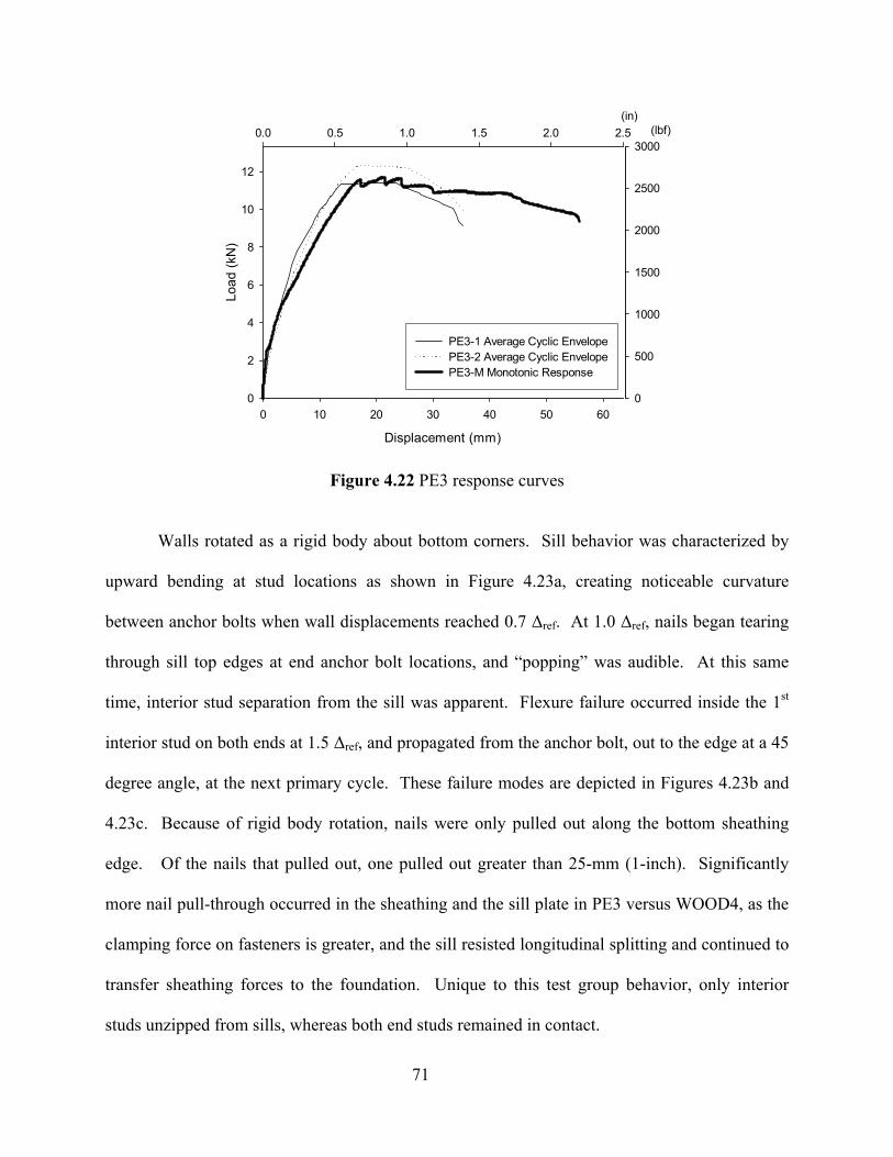
71
Displacement (mm)
0 10 20 30 40 50 60
Load
(kN
)
0
2
4
6
8
10
12
2-1 Average Cyclic Envelope2-2 Average Cyclic Envelope2-M Monotonic Response
(in)0.0 0.5 1.0 1.5 2.0 2.5 (lbf)
0
500
1000
1500
2000
2500
3000
PE3-1 Average Cyclic EnvelopePE3-2 Average Cyclic EnvelopePE3-M Monotonic Response
Figure 4.22 PE3 response curves
Walls rotated as a rigid body about bottom corners. Sill behavior was characterized by
upward bending at stud locations as shown in Figure 4.23a, creating noticeable curvature
between anchor bolts when wall displacements reached 0.7 ∆ref. At 1.0 ∆ref, nails began tearing
through sill top edges at end anchor bolt locations, and “popping” was audible. At this same
time, interior stud separation from the sill was apparent. Flexure failure occurred inside the 1st
interior stud on both ends at 1.5 ∆ref, and propagated from the anchor bolt, out to the edge at a 45
degree angle, at the next primary cycle. These failure modes are depicted in Figures 4.23b and
4.23c. Because of rigid body rotation, nails were only pulled out along the bottom sheathing
edge. Of the nails that pulled out, one pulled out greater than 25-mm (1-inch). Significantly
more nail pull-through occurred in the sheathing and the sill plate in PE3 versus WOOD4, as the
clamping force on fasteners is greater, and the sill resisted longitudinal splitting and continued to
transfer sheathing forces to the foundation. Unique to this test group behavior, only interior
studs unzipped from sills, whereas both end studs remained in contact.
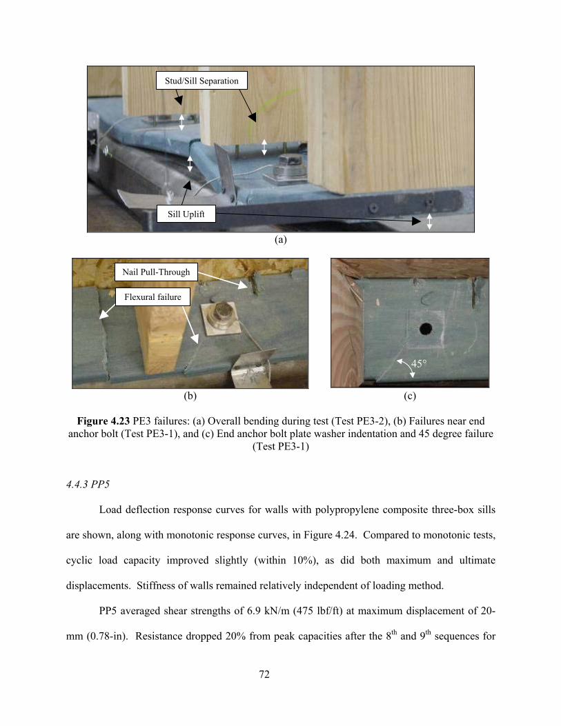
72
(a)
(b) (c)
Figure 4.23 PE3 failures: (a) Overall bending during test (Test PE3-2), (b) Failures near end
anchor bolt (Test PE3-1), and (c) End anchor bolt plate washer indentation and 45 degree failure (Test PE3-1)
4.4.3 PP5
Load deflection response curves for walls with polypropylene composite three-box sills
are shown, along with monotonic response curves, in Figure 4.24. Compared to monotonic tests,
cyclic load capacity improved slightly (within 10%), as did both maximum and ultimate
displacements. Stiffness of walls remained relatively independent of loading method.
PP5 averaged shear strengths of 6.9 kN/m (475 lbf/ft) at maximum displacement of 20-
mm (0.78-in). Resistance dropped 20% from peak capacities after the 8th and 9th sequences for
Flexural failure
Nail Pull-Through
45°
Stud/Sill Separation
Sill Uplift

73
Test 3-1 and 3-2, respectively. At these points of failure, average load and displacement reached
13.5-kN (3038-lbf) and 25-mm (0.99-in). A ductility factor of 2.6 was achieved at failure, along
with 1532 kN-mm (13,562 lbf-in) of energy dissipation.
Displacement (mm)0 5 10 15 20 25 30 35
Load
(kN
)
0
2
4
6
8
10
12
14
16
18
20
22
3-1 Average Cyclic Envelope3-2 Average Cyclic Envelope3-M Monotonic Response
(in)0.0 0.2 0.4 0.6 0.8 1.0 1.2 1.4 (lbf)
0
1000
2000
3000
4000
5000
PP5-1 Average Cyclic EnvelopePP5-2 Average Cyclic EnvelopePP5-M Monotonic Response
Figure 4.24 PP5 response curves
Behavior for PP5 was rigid body motion, with studs separating from the sill plate, along
with sill plate rotation. Audible signs of failure did not occur until reaching 1.0 ∆ref—probable
failure between the web and flange in the outside box of sections. By 1.5 ∆ref, catastrophic
failure occurred, splitting down the entire section along strands. Flexural failure also occurred at
end anchor bolts, along with complete blow-out of part of the top flange near the anchor bolt.
The splitting along the sill and between strands is illustrated in Figure 4.25. Nail tear-out of
sheathing was not nearly as frequent as in PE3, and nail pull-out occurred only at the bottom
row, near sill ends. Sheathing remained flush to stud edges.
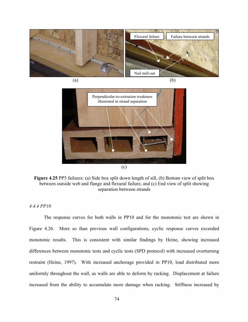
74
(a) (b)
(c)
Figure 4.25 PP5 failures: (a) Side box split down length of sill, (b) Bottom view of split box
between outside web and flange and flexural failure, and (c) End view of split showing separation between strands
4.4.4 PP10
The response curves for both walls in PP10 and for the monotonic test are shown in
Figure 4.26. More so than previous wall configurations, cyclic response curves exceeded
monotonic results. This is consistent with similar findings by Heine, showing increased
differences between monotonic tests and cyclic tests (SPD protocol) with increased overturning
restraint (Heine, 1997). With increased anchorage provided in PP10, load distributed more
uniformly throughout the wall, as walls are able to deform by racking. Displacement at failure
increased from the ability to accumulate more damage when racking. Stiffness increased by
Flexural failure Failure between strands
Nail pull-out
Perpendicular-to-extrusion weakness illustrated in strand separation
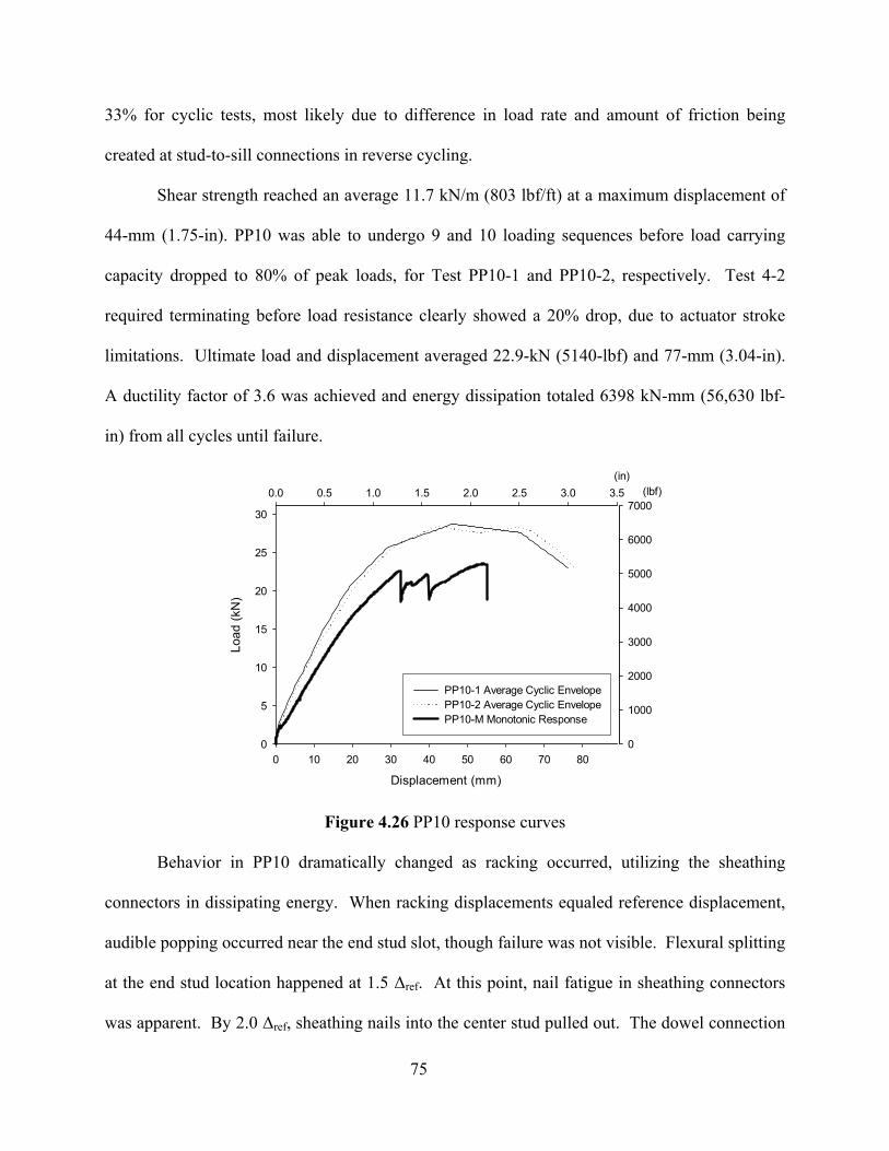
75
33% for cyclic tests, most likely due to difference in load rate and amount of friction being
created at stud-to-sill connections in reverse cycling.
Shear strength reached an average 11.7 kN/m (803 lbf/ft) at a maximum displacement of
44-mm (1.75-in). PP10 was able to undergo 9 and 10 loading sequences before load carrying
capacity dropped to 80% of peak loads, for Test PP10-1 and PP10-2, respectively. Test 4-2
required terminating before load resistance clearly showed a 20% drop, due to actuator stroke
limitations. Ultimate load and displacement averaged 22.9-kN (5140-lbf) and 77-mm (3.04-in).
A ductility factor of 3.6 was achieved and energy dissipation totaled 6398 kN-mm (56,630 lbf-
in) from all cycles until failure.
Displacement (mm)
0 10 20 30 40 50 60 70 80
Load
(kN
)
0
5
10
15
20
25
30
4-1 Average Cyclic Envelope4-2 Average Cyclic Envelope4-M Monotonic Response
(in)0.0 0.5 1.0 1.5 2.0 2.5 3.0 3.5 (lbf)
0
1000
2000
3000
4000
5000
6000
7000
PP10-1 Average Cyclic EnvelopePP10-2 Average Cyclic EnvelopePP10-M Monotonic Response
Figure 4.26 PP10 response curves
Behavior in PP10 dramatically changed as racking occurred, utilizing the sheathing
connectors in dissipating energy. When racking displacements equaled reference displacement,
audible popping occurred near the end stud slot, though failure was not visible. Flexural splitting
at the end stud location happened at 1.5 ∆ref. At this point, nail fatigue in sheathing connectors
was apparent. By 2.0 ∆ref, sheathing nails into the center stud pulled out. The dowel connection
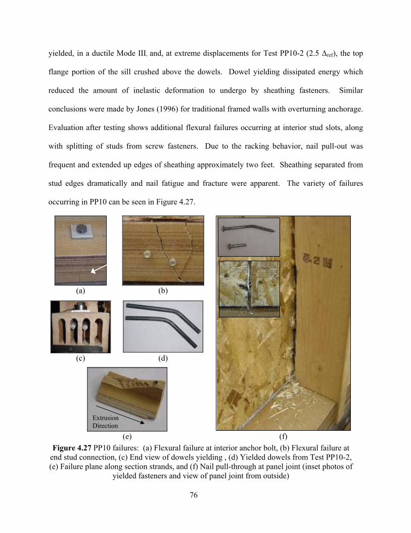
76
yielded, in a ductile Mode III, and, at extreme displacements for Test PP10-2 (2.5 ∆ref), the top
flange portion of the sill crushed above the dowels. Dowel yielding dissipated energy which
reduced the amount of inelastic deformation to undergo by sheathing fasteners. Similar
conclusions were made by Jones (1996) for traditional framed walls with overturning anchorage.
Evaluation after testing shows additional flexural failures occurring at interior stud slots, along
with splitting of studs from screw fasteners. Due to the racking behavior, nail pull-out was
frequent and extended up edges of sheathing approximately two feet. Sheathing separated from
stud edges dramatically and nail fatigue and fracture were apparent. The variety of failures
occurring in PP10 can be seen in Figure 4.27.
(a) (b)
(c) (d)
(e) (f)
Figure 4.27 PP10 failures: (a) Flexural failure at interior anchor bolt, (b) Flexural failure at end stud connection, (c) End view of dowels yielding , (d) Yielded dowels from Test PP10-2, (e) Failure plane along section strands, and (f) Nail pull-through at panel joint (inset photos of
yielded fasteners and view of panel joint from outside)
Extrusion Direction
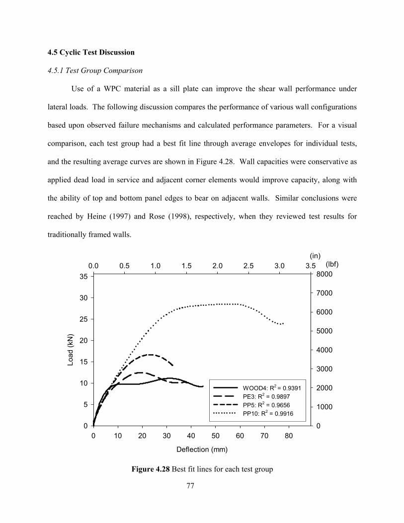
77
4.5 Cyclic Test Discussion
4.5.1 Test Group Comparison
Use of a WPC material as a sill plate can improve the shear wall performance under
lateral loads. The following discussion compares the performance of various wall configurations
based upon observed failure mechanisms and calculated performance parameters. For a visual
comparison, each test group had a best fit line through average envelopes for individual tests,
and the resulting average curves are shown in Figure 4.28. Wall capacities were conservative as
applied dead load in service and adjacent corner elements would improve capacity, along with
the ability of top and bottom panel edges to bear on adjacent walls. Similar conclusions were
reached by Heine (1997) and Rose (1998), respectively, when they reviewed test results for
traditionally framed walls.
Deflection (mm)
0 10 20 30 40 50 60 70 80
Load
(kN
)
0
5
10
15
20
25
30
35
TG1 RegressionTG2 RegressionTG3 RegressionTG4 Regression
(in)0.0 0.5 1.0 1.5 2.0 2.5 3.0 3.5 (lbf)
0
1000
2000
3000
4000
5000
6000
7000
8000
WOOD4: R2 = 0.9391PE3: R2 = 0.9897PP5: R2 = 0.9656PP10: R2 = 0.9916
Figure 4.28 Best fit lines for each test group
78
Cyclic test results of walls with a solid polyethylene sill may be compared to that of
traditional walls with treated-wood sill plates in WOOD4. Similar loads, and therefore shear
strengths (10% increase), were achieved. Though with an increased yield displacement (40%)
and decreased maximum and ultimate displacements, and elastic shear stiffness decreased
resulting in reduced wall ductility. Attributable to lowered displacement capacities, energy
dissipation from cycles up to failure decreased by almost 40% for walls with a polyethylene
WPC sill. This section, if having equivalent thickness to 38-mm (nominal 2x) wood sill plates
could potentially have a larger improvement in performance, due to increased flexural resistance
of the sill plate.
PP5 test results show improved load capacities, 50% over that of WOOD4. Similar to
PE3 improvements, yield displacements of PP5 increased by at least 50%, consequently lowering
elastic stiffness. With a decrease in maximum and ultimate displacements due to brittle failure,
the ductility was reduced tremendously. As expected from such brittle failure, energy dissipation
decreased by 40%. Despite these disadvantages on earthquake performance, walls with the
three-box polypropylene section were able to provide over 50% more shear strength than the
traditional wood sill plate. To capitalize on this wall configuration’s improved shear strength,
weaknesses in the perpendicular-to-extrusion direction in the section must be addressed to
provide desirable earthquake performance. Surface reinforcement, section profile changes, or
elimination of die stranding could be viable options to improve upon sill plate behavior.
Comparing WPC sill plates intended for direct substitution (PE3 and PP5), negligible
difference is found in energy dissipation abilities, as well as in elastic shear stiffness. Though,
due to the brittle behavior of PP5, ductility decreased by almost 45% compared to PE3.
Weaknesses between strands of PP5’s section created brittle failure mechanisms and catastrophic
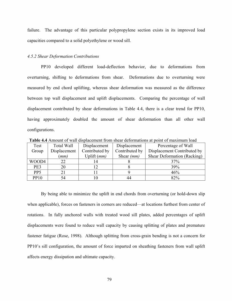
79
failure. The advantage of this particular polypropylene section exists in its improved load
capacities compared to a solid polyethylene or wood sill.
4.5.2 Shear Deformation Contributions
PP10 developed different load-deflection behavior, due to deformations from
overturning, shifting to deformations from shear. Deformations due to overturning were
measured by end chord uplifting, whereas shear deformation was measured as the difference
between top wall displacement and uplift displacements. Comparing the percentage of wall
displacement contributed by shear deformations in Table 4.4, there is a clear trend for PP10,
having approximately doubled the amount of shear deformation than all other wall
configurations.
Table 4.4 Amount of wall displacement from shear deformations at point of maximum load Test
Group Total Wall
Displacement (mm)
Displacement Contributed by
Uplift (mm)
Displacement Contributed by
Shear (mm)
Percentage of Wall Displacement Contributed by Shear Deformation (Racking)
WOOD4 22 14 8 37% PE3 20 12 8 39% PP5 21 11 9 46% PP10 54 10 44 82%
By being able to minimize the uplift in end chords from overturning (or hold-down slip
when applicable), forces on fasteners in corners are reduced—at locations furthest from center of
rotations. In fully anchored walls with treated wood sill plates, added percentages of uplift
displacements were found to reduce wall capacity by causing splitting of plates and premature
fastener fatigue (Rose, 1998). Although splitting from cross-grain bending is not a concern for
PP10’s sill configuration, the amount of force imparted on sheathing fasteners from wall uplift
affects energy dissipation and ultimate capacity.
80
4.5.3 Earthquake Performance Evaluation of PP10
The most significant improvement in PP10 performance over conventional wood sill wall
configurations existed in the 155% increase in energy dissipation for all cycles up until failure.
This is attributable to the racking behavior of the system, distributing load to all components and
allowing greater than 160% more load than conventional wood sill configurations (at peak
capacity) to be carried, and having improved displacement capacity. It can be inferred that these
increases would be even more substantial had there been a bottom row of sheathing nails
attaching the sheathing to the sill member. For future improvements, the section could be
redesigned to provide an extended ledge into which to fasten the sheathing, similar to blocking.
PP10 had improved results for all parameters except for elastic stiffness and ductility.
Yield displacements increased due to yield load increasing by over 100%. Yield displacements
showed additional increases due to a decrease in stiffness of approximately 30%. Ductility
decreases for PP10 as compared to ductility ratios for previous tests. However, due to the
significant changes that occurred in load capacity and displacement capacity, the entire load-
deflection behavior is dramatically different for PP10. Ductility may not fully describe the
changes in behavior in comparison to WOOD4, PE3, and PP5.
In order to predict successful earthquake behavior, ultimate displacements, stiffness, and
energy dissipation must be considered in addition to ductility. For design purposes, peak loads
will also be considered. The data in this study is compared to results by Salenikovich (2000) and
Langlois (2002), testing similar wall configurations with and without full anchorage (Table 4.5).
The tests with overturning anchorage, having larger load capacities and displacement capacities,
will be closer in their load-deflection behavior to PP10 to provide comparisons. It should be
noted that results from walls tested using the Sequential Phased Displacement (SPD) protocol
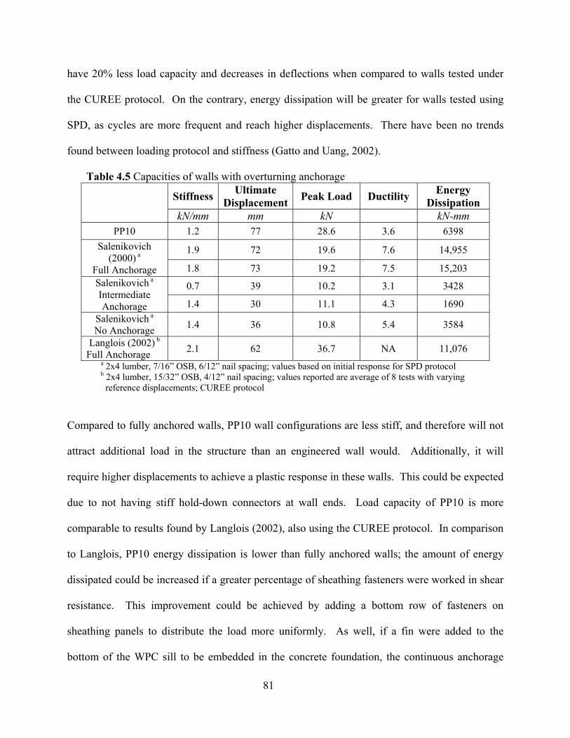
81
have 20% less load capacity and decreases in deflections when compared to walls tested under
the CUREE protocol. On the contrary, energy dissipation will be greater for walls tested using
SPD, as cycles are more frequent and reach higher displacements. There have been no trends
found between loading protocol and stiffness (Gatto and Uang, 2002).
Table 4.5 Capacities of walls with overturning anchorage
Stiffness Ultimate Displacement Peak Load Ductility Energy
Dissipation kN/mm mm kN kN-mm
PP10 1.2 77 28.6 3.6 6398
1.9 72 19.6 7.6 14,955 Salenikovich (2000) a
Full Anchorage 1.8 73 19.2 7.5 15,203
0.7 39 10.2 3.1 3428 Salenikovich a Intermediate Anchorage 1.4 30 11.1 4.3 1690
Salenikovich a No Anchorage 1.4 36 10.8 5.4 3584
Langlois (2002) b
Full Anchorage 2.1 62 36.7 NA 11,076 a 2x4 lumber, 7/16” OSB, 6/12” nail spacing; values based on initial response for SPD protocol b 2x4 lumber, 15/32” OSB, 4/12” nail spacing; values reported are average of 8 tests with varying reference displacements; CUREE protocol
Compared to fully anchored walls, PP10 wall configurations are less stiff, and therefore will not
attract additional load in the structure than an engineered wall would. Additionally, it will
require higher displacements to achieve a plastic response in these walls. This could be expected
due to not having stiff hold-down connectors at wall ends. Load capacity of PP10 is more
comparable to results found by Langlois (2002), also using the CUREE protocol. In comparison
to Langlois, PP10 energy dissipation is lower than fully anchored walls; the amount of energy
dissipated could be increased if a greater percentage of sheathing fasteners were worked in shear
resistance. This improvement could be achieved by adding a bottom row of fasteners on
sheathing panels to distribute the load more uniformly. As well, if a fin were added to the
bottom of the WPC sill to be embedded in the concrete foundation, the continuous anchorage
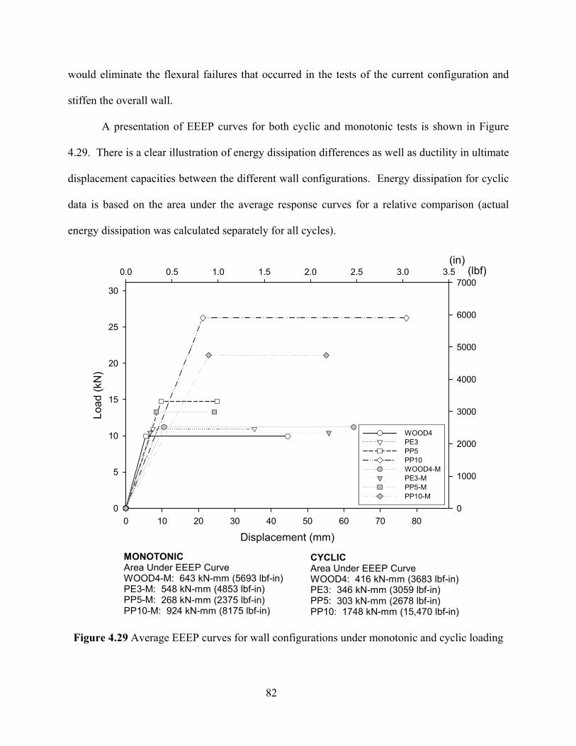
82
would eliminate the flexural failures that occurred in the tests of the current configuration and
stiffen the overall wall.
A presentation of EEEP curves for both cyclic and monotonic tests is shown in Figure
4.29. There is a clear illustration of energy dissipation differences as well as ductility in ultimate
displacement capacities between the different wall configurations. Energy dissipation for cyclic
data is based on the area under the average response curves for a relative comparison (actual
energy dissipation was calculated separately for all cycles).
(in)0.0 0.5 1.0 1.5 2.0 2.5 3.0 3.5 (lbf)
0
1000
2000
3000
4000
5000
6000
7000
Displacement (mm)0 10 20 30 40 50 60 70 80
Load
(kN
)
0
5
10
15
20
25
30
WOOD4PE3PP5PP10WOOD4-MPE3-MPP5-MPP10-M
CYCLICArea Under EEEP CurveWOOD4: 416 kN-mm (3683 lbf-in)PE3: 346 kN-mm (3059 lbf-in)PP5: 303 kN-mm (2678 lbf-in)PP10: 1748 kN-mm (15,470 lbf-in)
MONOTONICArea Under EEEP CurveWOOD4-M: 643 kN-mm (5693 lbf-in)PE3-M: 548 kN-mm (4853 lbf-in)PP5-M: 268 kN-mm (2375 lbf-in)PP10-M: 924 kN-mm (8175 lbf-in)
Figure 4.29 Average EEEP curves for wall configurations under monotonic and cyclic loading
83
The ductility of PP10 compares closely with the full anchorage walls tested by
Salenikovich (2000), though loads are still quite different. Ductility ratios provided by
Salenikovich are double PP10. Also considering damage, it can be inferred the PP10
configurations provide a better solution that will have more integrity remaining after wall
damage has occurred. Unlike wood walls, PP10 walls do not split longitudinally down the plate
and still retain lateral sliding capacity.
4.5.4 Comparison of Monotonic and Cyclic Results
Response of walls under cyclic and monotonic tests was not found to be significantly
different in previous shear wall testing. The CUREE protocol produces peak loads fairly close to
monotonic loads (Gatto and Uang, 2002). If differences occur, studies have shown monotonic
tests to result in slightly higher response than cyclic tests. Studies by Langlois (2002), using the
CUREE protocol, and Heine (1997), using the SPD cyclic method, found this to be true for the
majority of their tests. Because monotonic capacities were often higher than cyclic shear wall
capacities, the City of Los Angeles Department of Building and Safety required a 25% reduction
in design shear load for seismic design after the Northridge earthquake to avoid non-conservative
designs. (Rose, 1998). Langlois (2002) found monotonic response was slightly lower than cyclic
only for walls without uplift anchorage. It was rationalized that for walls without full
anchorage, it is common for cyclic results to exceed monotonic results as more energy is
dissipated in unzipping of studs in reversed cycles.
The ratios of maximum loads for cyclic tests compared to monotonic tests completed in
this study are included in Table 4.6. Tests performed in this study show that monotonic results
for PE3, PP5, and PP10 under-performed cyclic tests at maximum load, while WOOD4
monotonic results exceeded cyclic results. Walls PE3, PP5, and PP10 have as much as a 20%
84
increase in capacity when loaded cyclically. This increase could potentially be an advantage to
utilizing WPC material for cyclic loading applications. The reason for this reverse trend may be
in the material behavior of the thermoplastic sill plates, resulting in a change in distribution of
load demand on the sheathing fasteners. In particular, the higher resistance for WPC sill plates
in bearing/clamping of fasteners may reduce the amount of localized crushing at connections in
cyclic loading. As well, the increased load rate for cyclic tests, as compared to monotonic tests,
may contribute to higher resistance in connections. The limited number of samples and wide
amount of variables makes this inconclusive and requires further study.
Table 4.6 Comparison of monotonic and cyclic wall capacities
Test Group
Ppeak_cyclic / Ppeak_monotonic
WOOD4 0.85 PE3 1.01 PP5 1.07 PP10 1.21
4.5.5 Cyclic Stiffness
The stiffness of systems is important in predicting how loads distribute through a
structure. In the case of lateral force resisting systems, stiffness of shear walls (and rigidity of
diaphragms) determine the amount of lateral forces attracted (Paevere et al, 2003). The elastic
stiffness of cyclic tests progressively decreased from WOOD4 to PP10 (as much as 32%).
According to Heine (1997), anchorage does not influence cyclic stiffness. Therefore, one may
conclude that the difference in stiffness is more of a system effect, resulting from connection
slack, and load distribution among sheathing fasteners and stud connections. Because of this
decrease in stiffness and higher yield loads, PP10 walls theoretically did not achieve plastic
behavior until 21-mm (0.84-inches) of lateral deflection. This deflection is approaching 1/3 of
the maximum story drift limit (2.5%) when structural damage may occur (ICBO, 2000b). The
85
majority of this wall displacement is due to racking, as stud uplift only accounts for a maximum
of 3-mm (0.125-inches). The elastic stiffness must increase to provide a wall that has better
ability to control deflections in the elastic range in normal service conditions. By stiffening the
wall, smaller forces will not cause large amounts of damage in adjacent systems, and yielding
will occur at smaller displacements, beginning greater energy dissipation from plastic
deformation. Because large displacements are in shear deflections, a change to the design that
could provide increased stiffness is installing fasteners along the bottom edge of the wall
sheathing. This would allow force to transfer to interior studs rather than remaining concentrated
at the center and end studs where dense nailing results in additional stiffness. Another solution
to reduce the amount of stud movement from its vertical position would be to eliminate
connection slack in dowels and extra space within end slots that allow stud rotation within the
plane of the wall with shims or other means.
Taking a further look at stiffness performance, and how it degrades with each subsequent
cycle, a better estimate of design success may be made. Figure 4.30 plots stiffness with
increasing displacement—at the peak of each cycle for both positive and negative envelopes.
Because of the non-linearity of shear wall behavior, stiffness is not constant during one loading
cycle. Therefore, the stiffness was estimated by passing a line through the origin and point of
maximum load and corresponding displacement. A full list of stiffness values for each cycle can
be found in Table B.17 in Appendix B. WOOD4 has the fastest degradation in stiffness as
cycles proceed, resulting from the brittle splitting of wood sill plates in early cycles. PE3 mimics
this stiffness degradation, though having a quicker drop in stiffness at wall deflections of 12-mm
(0.5-in), resulting from flexural failures of the sill plate. PP5 has low stiffness degradation in
beginning cycles, but then drops suddenly from brittle and complete splitting in the outside box
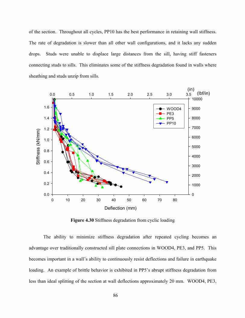
86
of the section. Throughout all cycles, PP10 has the best performance in retaining wall stiffness.
The rate of degradation is slower than all other wall configurations, and it lacks any sudden
drops. Studs were unable to displace large distances from the sill, having stiff fasteners
connecting studs to sills. This eliminates some of the stiffness degradation found in walls where
sheathing and studs unzip from sills.
Deflection (mm)
0 10 20 30 40 50 60 70 80
Stiff
ness
(kN
/mm
)
0.0
0.2
0.4
0.6
0.8
1.0
1.2
1.4
1.6Test Group 1Test Group 2Test Group 3Test Group 4
(in)0.0 0.5 1.0 1.5 2.0 2.5 3.0 3.5 (lbf/in)
0
1000
2000
3000
4000
5000
6000
7000
8000
9000
10000
WOOD4PE3PP5PP10
Figure 4.30 Stiffness degradation from cyclic loading
The ability to minimize stiffness degradation after repeated cycling becomes an
advantage over traditionally constructed sill plate connections in WOOD4, PE3, and PP5. This
becomes important in a wall’s ability to continuously resist deflections and failure in earthquake
loading. An example of brittle behavior is exhibited in PP5’s abrupt stiffness degradation from
less than ideal splitting of the section at wall deflections approximately 20 mm. WOOD4, PE3,
87
and PP10 had similar shapes to their degradation curves, however Groups 1 and 2 had increased
stiffness degradation. This has been found in previous studies to approximate an exponential
decrease (Heine, 1997). Also a benefit from slower loss of stiffness is the continued ability of
the wall to dissipate energy, another reason for WOOD4 wall configuration having superior
performance.
4.5.6 Cyclic Test Results
Cyclic shear wall tests exhibit successful performance for WPC sill plates when subjected
to reversed loading.
• Cyclic test behavior exceeded monotonic test response for walls with WPC sill plates,
most dramatically for PP10, having an increase of 20% in peak performance. Due to
changed load distribution throughout sheathing fasteners (possibly from improved
bearing/clamping forces in WPC sill plates), this better performance may be a motivating
factor in utilizing composite material in cyclic load applications.
• PE3 wall configuration would be a suitable substitution for wood sill walls, however
improvements in energy dissipation and ductility could be achieved by providing a
section with a thickness equal to 38-mm (2x nominal) depth.
• PP5 exhibited brittle failure and weakness between strands, suggesting the need for
section improvement before further utilization is possible. Improvements should be made
in order to resist tension forces perpendicular-to-extrusion at the sheathing connection, as
well as at the line of anchor bolts where bending occurs due to the eccentricity between
sheathing uplift and anchor bolt resistance.
• PP10 exhibits significantly improved load and deflection capacities by enabling racking
movements—achieving performance resembling fully anchored wall assemblies.
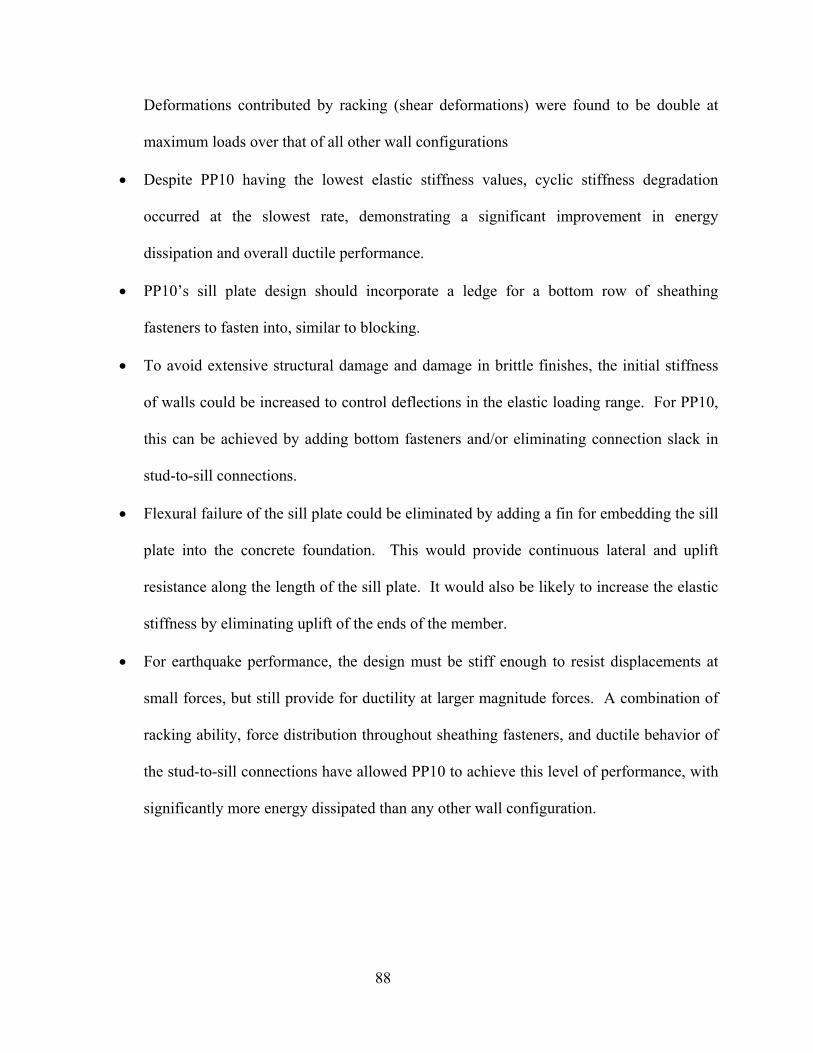
88
Deformations contributed by racking (shear deformations) were found to be double at
maximum loads over that of all other wall configurations
• Despite PP10 having the lowest elastic stiffness values, cyclic stiffness degradation
occurred at the slowest rate, demonstrating a significant improvement in energy
dissipation and overall ductile performance.
• PP10’s sill plate design should incorporate a ledge for a bottom row of sheathing
fasteners to fasten into, similar to blocking.
• To avoid extensive structural damage and damage in brittle finishes, the initial stiffness
of walls could be increased to control deflections in the elastic loading range. For PP10,
this can be achieved by adding bottom fasteners and/or eliminating connection slack in
stud-to-sill connections.
• Flexural failure of the sill plate could be eliminated by adding a fin for embedding the sill
plate into the concrete foundation. This would provide continuous lateral and uplift
resistance along the length of the sill plate. It would also be likely to increase the elastic
stiffness by eliminating uplift of the ends of the member.
• For earthquake performance, the design must be stiff enough to resist displacements at
small forces, but still provide for ductility at larger magnitude forces. A combination of
racking ability, force distribution throughout sheathing fasteners, and ductile behavior of
the stud-to-sill connections have allowed PP10 to achieve this level of performance, with
significantly more energy dissipated than any other wall configuration.
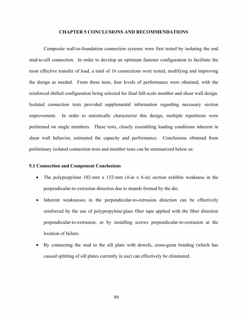
89
CHAPTER 5 CONCLUSIONS AND RECOMMENDATIONS
Composite wall-to-foundation connection systems were first tested by isolating the end
stud-to-sill connection. In order to develop an optimum fastener configuration to facilitate the
most effective transfer of load, a total of 16 connections were tested, modifying and improving
the design as needed. From these tests, four levels of performance were obtained, with the
reinforced shifted configuration being selected for final full-scale member and shear wall design.
Isolated connection tests provided supplemental information regarding necessary section
improvement. In order to statistically characterize this design, multiple repetitions were
performed on single members. These tests, closely resembling loading conditions inherent in
shear wall behavior, estimated the capacity and performance. Conclusions obtained from
preliminary isolated connection tests and member tests can be summarized below as:
5.1 Connection and Component Conclusions
• The polypropylene 102-mm x 152-mm (4-in x 6-in) section exhibits weakness in the
perpendicular-to-extrusion direction due to strands formed by the die.
• Inherent weaknesses in the perpendicular-to-extrusion direction can be effectively
reinforced by the use of polypropylene/glass fiber tape applied with the fiber direction
perpendicular-to-extrusion, or by installing screws perpendicular-to-extrusion at the
location of failure.
• By connecting the stud to the sill plate with dowels, cross-grain bending (which has
caused splitting of sill plates currently in use) can effectively be eliminated.
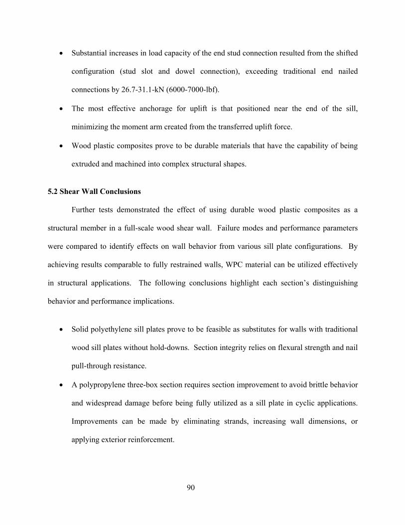
90
• Substantial increases in load capacity of the end stud connection resulted from the shifted
configuration (stud slot and dowel connection), exceeding traditional end nailed
connections by 26.7-31.1-kN (6000-7000-lbf).
• The most effective anchorage for uplift is that positioned near the end of the sill,
minimizing the moment arm created from the transferred uplift force.
• Wood plastic composites prove to be durable materials that have the capability of being
extruded and machined into complex structural shapes.
5.2 Shear Wall Conclusions
Further tests demonstrated the effect of using durable wood plastic composites as a
structural member in a full-scale wood shear wall. Failure modes and performance parameters
were compared to identify effects on wall behavior from various sill plate configurations. By
achieving results comparable to fully restrained walls, WPC material can be utilized effectively
in structural applications. The following conclusions highlight each section’s distinguishing
behavior and performance implications.
• Solid polyethylene sill plates prove to be feasible as substitutes for walls with traditional
wood sill plates without hold-downs. Section integrity relies on flexural strength and nail
pull-through resistance.
• A polypropylene three-box section requires section improvement to avoid brittle behavior
and widespread damage before being fully utilized as a sill plate in cyclic applications.
Improvements can be made by eliminating strands, increasing wall dimensions, or
applying exterior reinforcement.
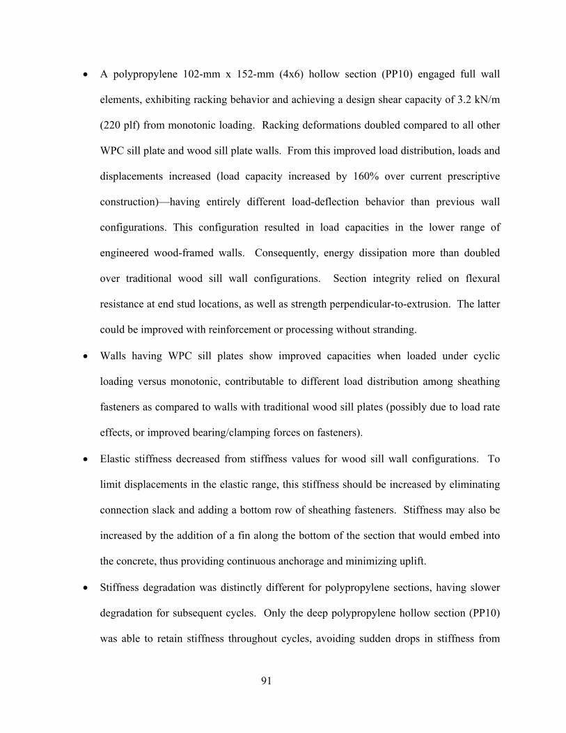
91
• A polypropylene 102-mm x 152-mm (4x6) hollow section (PP10) engaged full wall
elements, exhibiting racking behavior and achieving a design shear capacity of 3.2 kN/m
(220 plf) from monotonic loading. Racking deformations doubled compared to all other
WPC sill plate and wood sill plate walls. From this improved load distribution, loads and
displacements increased (load capacity increased by 160% over current prescriptive
construction)—having entirely different load-deflection behavior than previous wall
configurations. This configuration resulted in load capacities in the lower range of
engineered wood-framed walls. Consequently, energy dissipation more than doubled
over traditional wood sill wall configurations. Section integrity relied on flexural
resistance at end stud locations, as well as strength perpendicular-to-extrusion. The latter
could be improved with reinforcement or processing without stranding.
• Walls having WPC sill plates show improved capacities when loaded under cyclic
loading versus monotonic, contributable to different load distribution among sheathing
fasteners as compared to walls with traditional wood sill plates (possibly due to load rate
effects, or improved bearing/clamping forces on fasteners).
• Elastic stiffness decreased from stiffness values for wood sill wall configurations. To
limit displacements in the elastic range, this stiffness should be increased by eliminating
connection slack and adding a bottom row of sheathing fasteners. Stiffness may also be
increased by the addition of a fin along the bottom of the section that would embed into
the concrete, thus providing continuous anchorage and minimizing uplift.
• Stiffness degradation was distinctly different for polypropylene sections, having slower
degradation for subsequent cycles. Only the deep polypropylene hollow section (PP10)
was able to retain stiffness throughout cycles, avoiding sudden drops in stiffness from

92
brittle failure. This measure of stiffness throughout cycles is an important indicator for
the wall’s ability to continuously resist cyclic loading and control displacements,
especially when behaving in a plastic manner.
• Stiffness, energy dissipation, ultimate loads, and resulting damage become more
revealing measures of earthquake behavior than ductility ratios between the tested wall
configurations due to differing load-deflection behavior.
• Compared to fully restrained walls completed in previous studies, the polypropylene
section must be improved to force loads to distribute more uniformly throughout
sheathing to efficiently utilize all components. This will provide more energy dissipation
that would be comparable with energy values reported for fully restrained wall
configurations.
5.3 Future Research
Results from this study are based on one monotonic test to determine reference
displacements and two cyclic tests for each wall configuration. Further testing would be
required to statistically conclude design loads and failure modes.
• Improvements in test methods would be to obtain more accurate cyclic load control
hardware to obtain consistent loading directions as well as collecting data more
frequently.
• Tests should be completed under monotonic versus cyclic loading to compare
performance of walls having WPC sill plates, to verify that wall behavior under cyclic
loading exceeds monotonic.
• Future research should focus on optimizing prototype sections tested in this study.
Though member test damage resembled that seen in full wall systems, a shear wall test
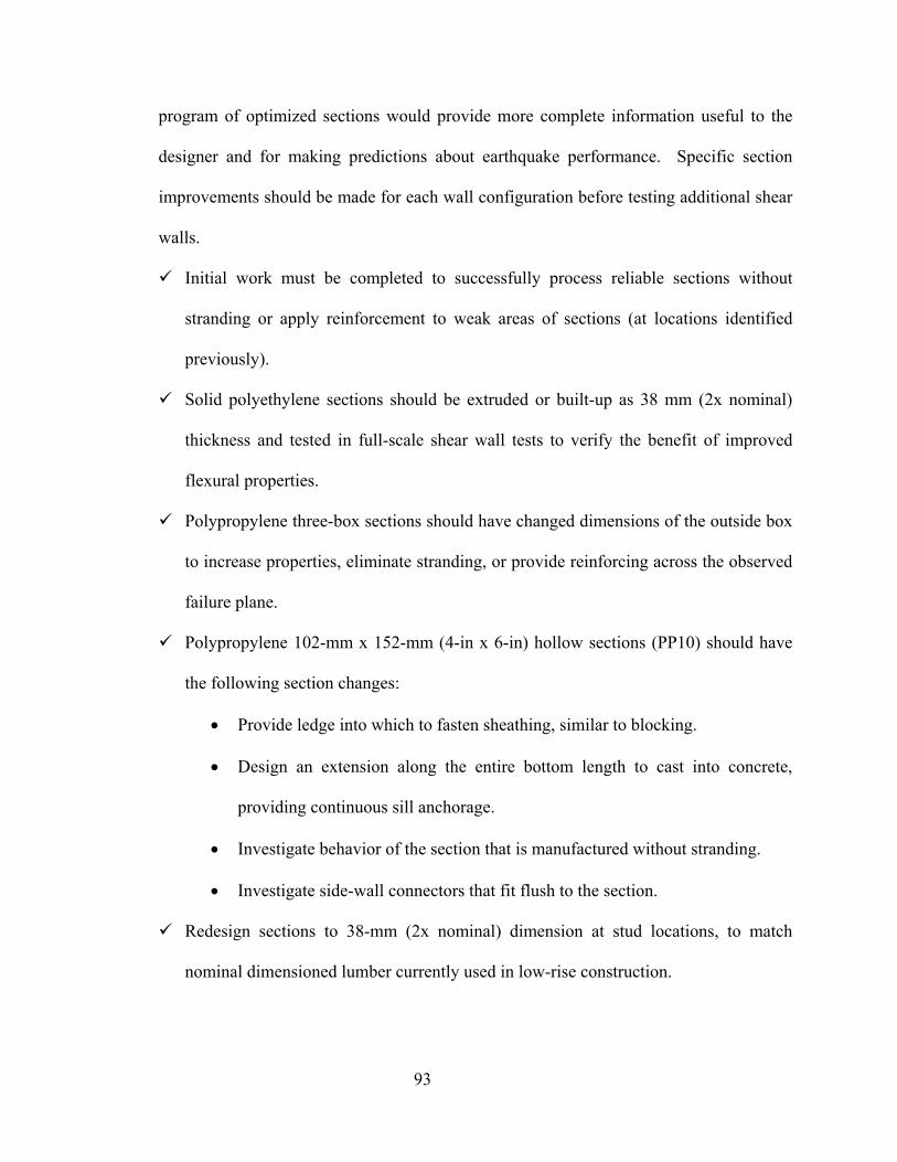
93
program of optimized sections would provide more complete information useful to the
designer and for making predictions about earthquake performance. Specific section
improvements should be made for each wall configuration before testing additional shear
walls.
Initial work must be completed to successfully process reliable sections without
stranding or apply reinforcement to weak areas of sections (at locations identified
previously).
Solid polyethylene sections should be extruded or built-up as 38 mm (2x nominal)
thickness and tested in full-scale shear wall tests to verify the benefit of improved
flexural properties.
Polypropylene three-box sections should have changed dimensions of the outside box
to increase properties, eliminate stranding, or provide reinforcing across the observed
failure plane.
Polypropylene 102-mm x 152-mm (4-in x 6-in) hollow sections (PP10) should have
the following section changes:
• Provide ledge into which to fasten sheathing, similar to blocking.
• Design an extension along the entire bottom length to cast into concrete,
providing continuous sill anchorage.
• Investigate behavior of the section that is manufactured without stranding.
• Investigate side-wall connectors that fit flush to the section.
Redesign sections to 38-mm (2x nominal) dimension at stud locations, to match
nominal dimensioned lumber currently used in low-rise construction.
94
Provide a solution for installing nail fasteners into wood plastic composite material
that will be economical and feasible for current construction methods.
• Tests should be performed on walls with different sheathing nail schedules, as well as
different sheathing and finish materials (interior and exterior), to determine the range of
design loads for the walls using this section.
• Further tests should investigate placement of anchor bolts in the 102-mm x 152-mm (4-in
x 6-in) WPC wall configurations—to identify optimal locations, if bolted, and changed
wall behavior, if continually anchored.
The data proving the feasibility of WPC structural members in shear wall systems can be
strengthened by making the necessary improvements in sections and in testing methods. The
information provided by this study sufficiently proved the structural capacities of these wood
plastic sections to be comparable to conventional structural material in earthquake applications,
and even demonstrate improved behavior and more ideal failure modes. In addition, this system
avoids chemicals that have potential to leach, and it provides a conscious effort to contribute
sustainable construction methods with durable materials.
95
REFERENCES
Adcock, Timothy, Wolcott, Michael P., and Hermanson, John C. (2001a). “The Influence of Wood Plastic Composite Formulation: Studies on mechanical and physical properties.” Project End Report. Engineered Wood Composites for Navy Waterfronts. Task 1D-1 Evaluate Extruded Materials. Washington State University. Pullman, Washington.
American Forest and Paper Association (AF&PA). (2001). Special Design Provisions for Wind
and Seismic Supplement. 2001 ed., AF&PA, Washington, DC. ASTM E564-00e1. (2000). “Standard Practice for Static Load Test for Shear Resistance of
Framed Walls for Buildings.” American Society of Testing Materials, Vol. 04.11. ASTM E2126-02a (2002). Standard Test Methods for Cyclic (Reversed) Load Test for Shear
Resistance of Framed Walls for Buildings, Vol. 04.12. Bracci, Joseph M., Stromatt, R. F., and Pollock, D. G. (1996). “Seismic Performance of
Confined Sill Plate Connections.” Journal of Structural Engineering, American Society of Civil Engineers. 122(11), 1357-1363.
Breyer, Donald E., Fridley, Kenneth J., Cobeen, Kelly, E. (1999). Design of Wood Structures
ASD. 4th Ed. McGraw-Hill, New York, New York. Clemons, Craig. (2002). “Wood-Plastic Composites in the United States: The Interfacing of Two
Industries.” Forest Products Journal, Forest Products Society, 52(6), 10-18. Cox, Caroline. (1991). “Chromated Copper Arsenate.” Journal of Pesticide Reform, 11(1), 2-6. CRD. (2003). “Conceptualized Reference Database for Building Envelope Research.” Building
Envelope Performance Laboratory.Centre for Building Studies. Department of Building, Civil and Environmental Engineering. Concordia University. Website: http://alcor.concordia.ca/~raojw/crd/index.html
CWC. (2004). “Types of Preservatives.” The Canadian Wood Council. Ottawa, Ontario. Day, Robert W. (1996). “Performance of Single Family House Foundations During Northridge
Earthquake.” Practice Periodical on Structural Design and Construction. 1(2). 85-88. Delli Quadri, Nicolino G. (2003). Los Angeles County. (personal correspondence). Gatto, Kip, and Uang, Chia-Ming. (2002). “Cyclic Response of Woodframe Shearwalls:
Loading Protocol and Rate of Loading Effects (CUREE Publication No. W-13),” CUREE, Richmond, CA.
Haiar, Kevin J. (2000). “Performance and Design of Prototype Wood-Plastic Composite
Sections.” Washington State University; Master Thesis.
96
Hall, John F. (2002). “CUREE – Caltech Wood-frame Project – Overview.” CUREE,
Richmond, CA. Hamburger, Ronald O. (1994). “Lessons Learned in the Northridge Earthquake on Wood Frame
Buildings.” Spring Seminar, Structural Engineers Association of Northern California (SEAoNC), San Francisco.
Heine, Christopher. (1997). “Effect of Overturning Restraint on the Performance of Fully
Sheathed and Perforated Timber Framed Shear Walls.” Virginia Tech; Master Thesis. ICBO. (1994). Suggested Revisions to the 1994 Editions of the Uniform Codes (Submittals for
1995). International Conference of Building Officials. Whittier, CA. ICBO (1996). 74th Annual Education and Code Development Conference. International
Conference of Building Officials. St. Paul, MN. ICBO. (2000a). International Residential Building Code. International Conference of Building
Officials. Whittier, CA. ICBO. (2000b). Uniform Building Code. International Conference of Building Officials,
Whittier, CA. Jones, Donald A. (1996). “Performance of Bolted Wood-To-Concrete Connections and Bolted
Connections in Plywood Shear Walls.” Texas A&M University; Master Thesis. Kiefer, Stephan. (1998). “Chapter 4 Connections” in Seismic Retrofit Training for Building
Contractors & Inspectors. Seminar Participant Handbook. http://www.abag.ca.gov/bayarea/eqmaps/fixit/manual
Kobbe, Ryan. (2005). “Creep Behavior of a Wood-Polypropylene Composite.” Washington
State University; Master Thesis. Krawinkler, Helmut, Parisi, Francisco, Ibarra, Luis, Ayoub, Ashraf, and Medina, Ricardo,
(2001). “Development of a Testing Protocol for Wood Frame Structures (CUREE Publication No. W-02),” CUREE, Richmond, CA.
Kubal, Michael T. (2000). Construction Waterproofing Handbook. McGraw-Hill. New York,
NY. Langlois, Jeffrey. (2002). “Effects of Reference Displacement and Damage Accumulation in
Wood Shear Walls Subjected to the CUREE Protocol.“ Oregon State University; Master Thesis.
Laver, T. C. (1996). Extruded synthetic wood composition and method for making same. Patent
number 5,516,472.

97
Mahaney, James. A., and Kehoe, Brian. E. (2002). “Anchorage of Wood-frame Buildings:
Laboratory Testing Report (CUREE Publication No. W-14),” CUREE, Richmond, CA. Martin, Zeno. (2003) APA—The Engineered Wood Association. (personal correspondence). Mapleston, P. (2001). “It’s One Hot Market for Profile Extruders.” Modern Plastics, June. Pp.
49-52. Meohle, Jack P. (1994). Preliminary report on the seismological and engineering aspects of the
January 17, 1994 Northridge earthquake. Earthquake Engineering Research Center, University of California, Berkeley, CA, Report UCB/EERC-94/01.
Morrison, Daniel S. (2004) “Pressure-Treated Wood: The Next Generation.” Fine
Homebuilding. No. 160. 82-85. National Design Specification (NDS). (2001). American Forest and Paper Association.
AF&PA, Washington, D.C. Paevere, Phillip, J., Foliente, Greg C., Kasal, Bo. (2003). “Load-Sharing and Redistribution in a
One-Story Woodframe Building.” Journal of Structural Engineering, American Society of Civil Engineers, 129(9), 1275-1284.
Pendleton, David, Hofford, Theresa.A., Adcock, Tim, Woodward, Bessie. and Wolcott, Michael
P. (2002). “Durability of an Extruded HDPE/Wood Composite.” Forest Products Journal, Forest Products Society, 52(6), 21-27.
Rose, John D. (1998). Preliminary Testing of Wood Structural Panel Shear Walls Under Cyclic
(Reversed) Loading. APA Research Report 158. APA The Engineered Wood Association, Tacoma, WA.
Rosowsky, David., Elkins, Lori, and Carroll, Cameron. (2004). “Cyclic tests of engineered
shearwalls considering different plate washer sizes.” For American Forest & Paper Association.
Salenikovich, Alexander. (2000). “The Racking Performance of Light-Frame Shear Walls.”
Virginia Tech; PhD Dissertation. Schierle, Goetz G. (2002). “Northridge Earthquake Field Investigations: Statistical Analysis of
Wood-frame Damage (CUREE Publication No. W-09),” CUREE, Richmond, CA. Showalter, John, Glowinski, Robert, Woodson, George, and Price, Eddie W. (2003). “Framing
the Future.” Forest Products Journal, Forest Products Society, 53(3), 4-9. Slaughter, Andrew E. (2004). “Design and Fatigue of a Structural Wood-Plastic Composites.”
Washington State University; Master Thesis.
98
Smart, Jason. (2002). “Capacity Resistance and Performance of Single-Shear Bolted and Nailed
Connections: An Experimental Investigation.” Virginia Tech; Master Thesis. Smith, Paul M. (2001). “U.S. Woodfiber-Plastic Composite Decking Market.” In: Proc. Sixth
International Conference on Woodfiber-Plastic Composites. Forest Products Society, Madison, WI. pp. 13-17.
Smulski, Stephen. (1996). “Wood-Destroying Fungi in Residential Construction” Wood Science
Specialists Inc. Shutesury, MA. http://alcor.concordia.ca/~raojw/crd/essay/essay000142.html

99
APPENDIX A: CONNECTION AND COMPONENT TEST RESULTS
A.1 Connection Test Fastener Configurations
Fastener geometry for connections between the polypropylene (PP10) sill plate and end
studs varied for each connection test. Tests 1-11 had end studs located at the end of the sill, as
traditional wood-frame construction uses. Tests 12-16 shifted the end stud in from the end of the
sill, as depicted by 108 mm end distances to the first fastener.
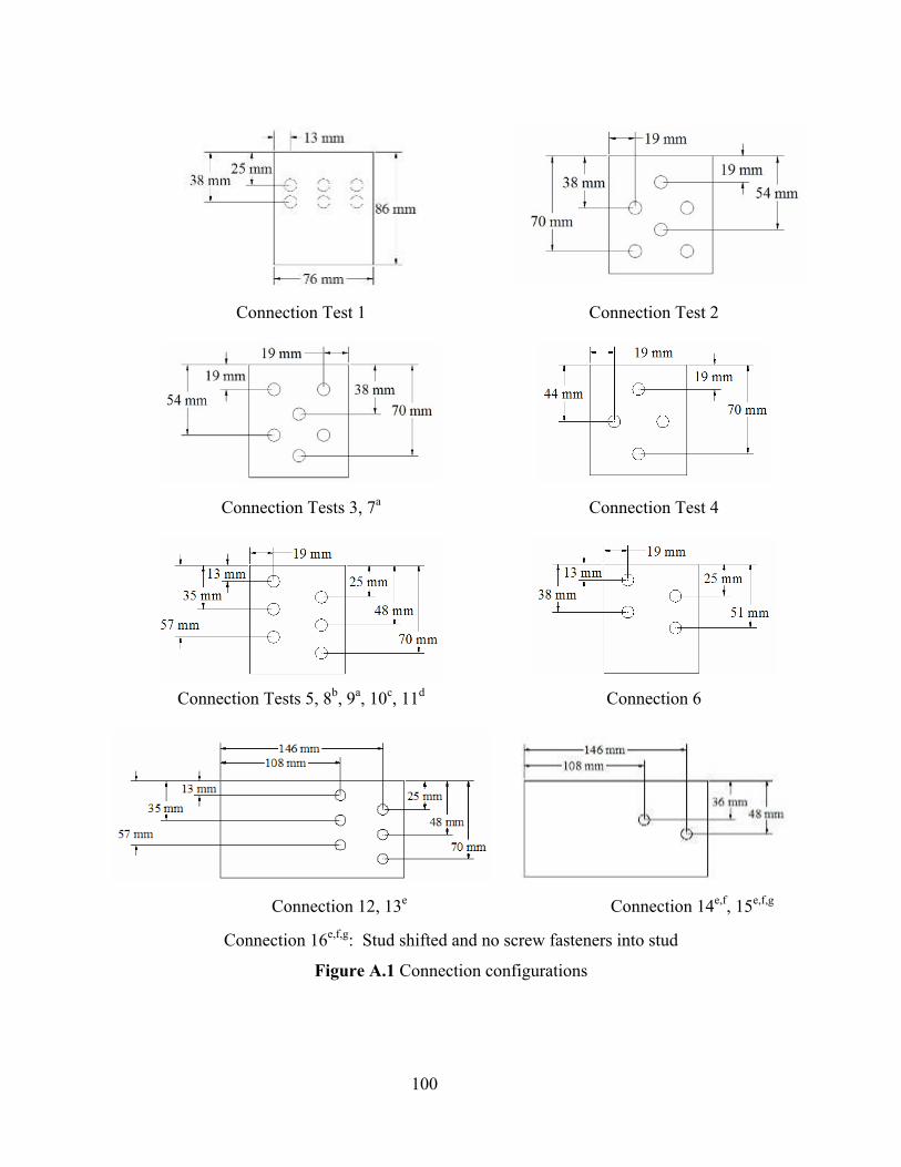
100
Connection Test 1
Connection Test 2
Connection Tests 3, 7a Connection Test 4
Connection Tests 5, 8b, 9a, 10c, 11d Connection 6
Connection 12, 13e Connection 14e,f, 15e,f,g
Connection 16e,f,g: Stud shifted and no screw fasteners into stud
Figure A.1 Connection configurations
101
a Helical threaded nails b Includes toe-nailed screws c Reinforced perpendicular-to-extrusion: Drywall screws d Reinforced perpendicular-to-extrusion: Fiberglass/PP tape e 13mm (1/2 in) Steel dowels f 9.5 mm x 76 mm x 152 mm (3/8 in x 3 in x 6 in) Plate washer g Reinforced with drywall screws at perpendicular-to-extrusion failures

102
A.2 Connection Test Failure Photos
Connection 1 Connection 2 Connection 3
Connection 4 Connection 5 Connection 6
Connection 7 Connection 8* Connection 9
Connection 10* Connection 11* Connection 12
*Screws toe-nailed from top of WPC into stud side not depicted
Figure A.2 Connection Tests 1-12 failure photos
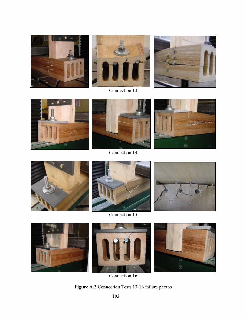
103
Connection 13
Connection 14
Connection 15
Connection 16
Figure A.3 Connection Tests 13-16 failure photos
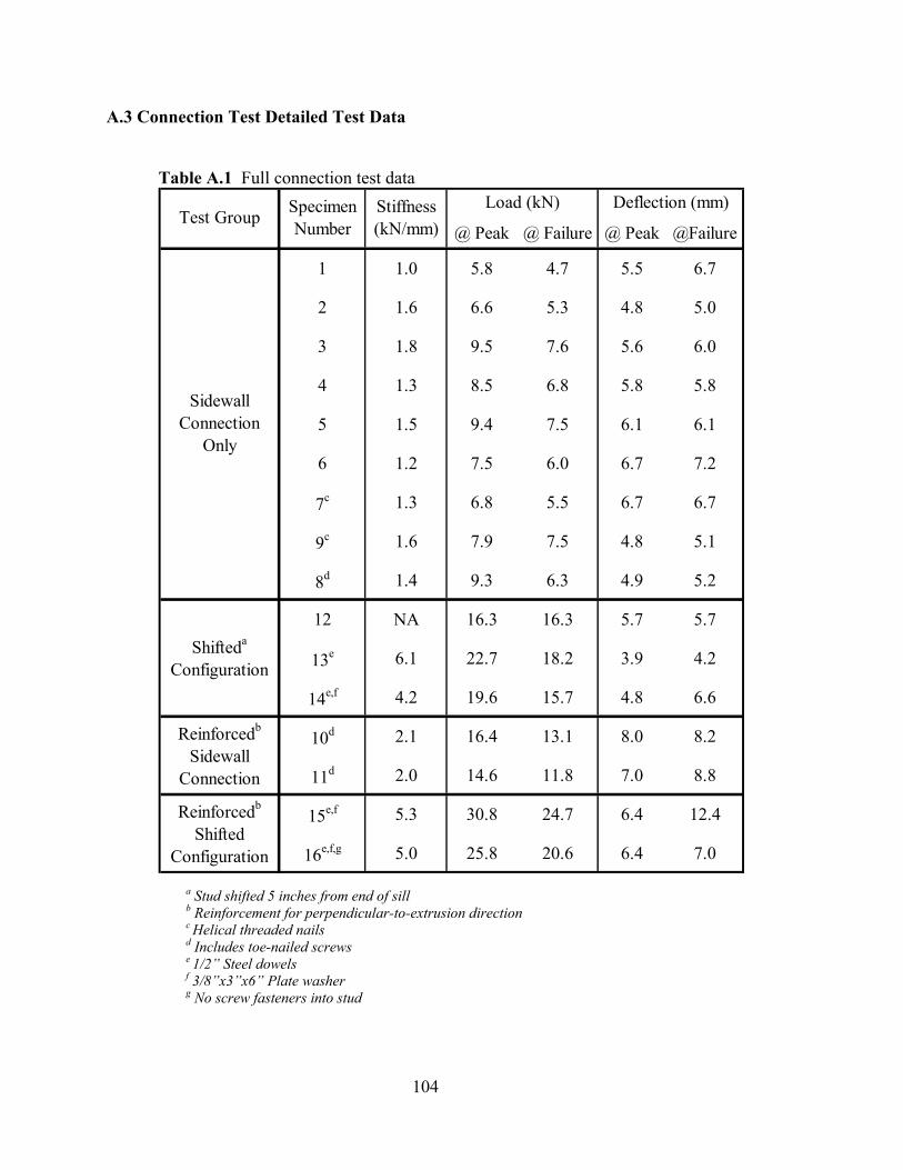
104
A.3 Connection Test Detailed Test Data
Table A.1 Full connection test data
@ Peak @ Failure @ Peak @Failure
1 1.0 5.8 4.7 5.5 6.7
2 1.6 6.6 5.3 4.8 5.0
3 1.8 9.5 7.6 5.6 6.0
4 1.3 8.5 6.8 5.8 5.8
5 1.5 9.4 7.5 6.1 6.1
6 1.2 7.5 6.0 6.7 7.2
7c 1.3 6.8 5.5 6.7 6.7
9c 1.6 7.9 7.5 4.8 5.1
8d 1.4 9.3 6.3 4.9 5.2
12 NA 16.3 16.3 5.7 5.7
13e 6.1 22.7 18.2 3.9 4.2
14e,f 4.2 19.6 15.7 4.8 6.6
10d 2.1 16.4 13.1 8.0 8.2
11d 2.0 14.6 11.8 7.0 8.8
15e,f 5.3 30.8 24.7 6.4 12.4
16e,f,g 5.0 25.8 20.6 6.4 7.0
Reinforcedb
Sidewall Connection
Specimen NumberTest Group
Shifteda
Configuration
Reinforcedb
Shifted Configuration
Stiffness (kN/mm)
Sidewall Connection
Only
Load (kN) Deflection (mm)
a Stud shifted 5 inches from end of sill b Reinforcement for perpendicular-to-extrusion direction c Helical threaded nails d Includes toe-nailed screws e 1/2” Steel dowels f 3/8”x3”x6” Plate washer g No screw fasteners into stud
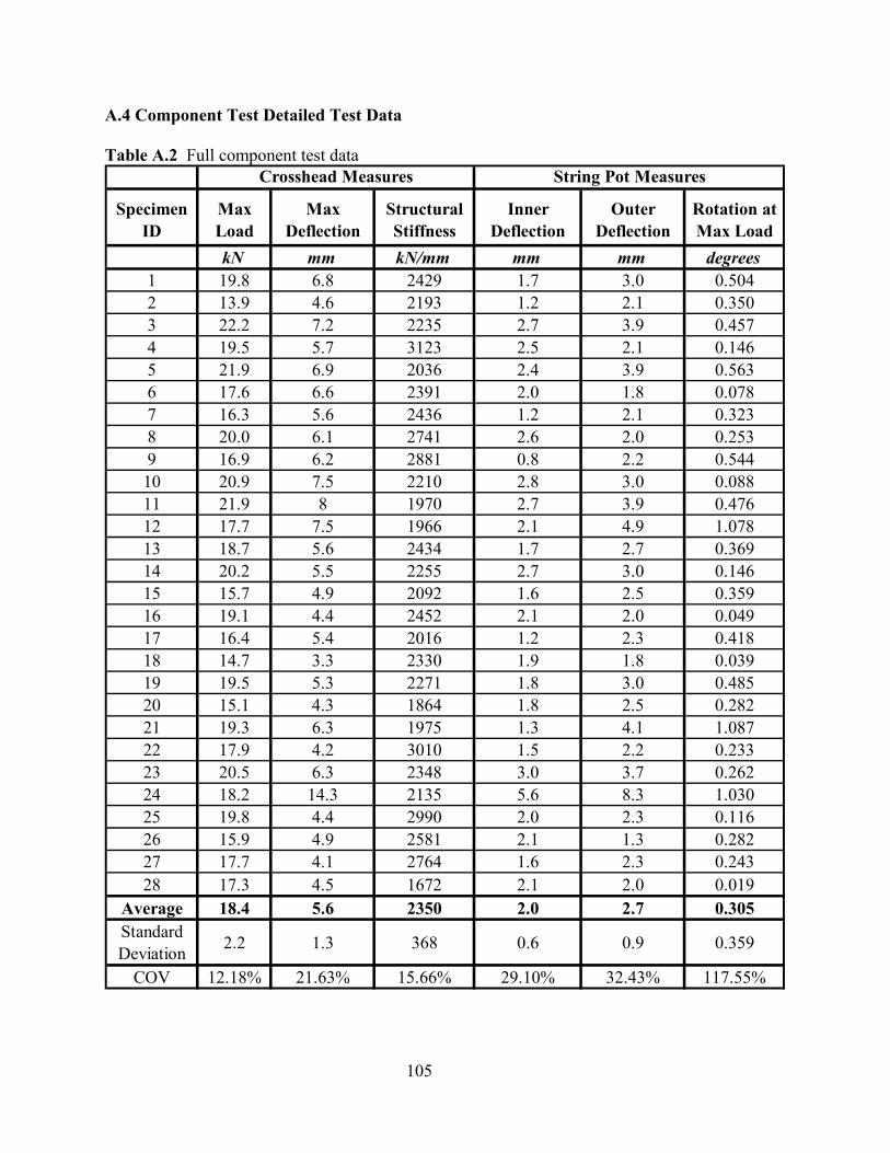
105
A.4 Component Test Detailed Test Data
Table A.2 Full component test data
Specimen ID
Max Load
Max Deflection
Structural Stiffness
Inner Deflection
Outer Deflection
Rotation at Max Load
kN mm kN/mm mm mm degrees1 19.8 6.8 2429 1.7 3.0 0.5042 13.9 4.6 2193 1.2 2.1 0.3503 22.2 7.2 2235 2.7 3.9 0.4574 19.5 5.7 3123 2.5 2.1 0.1465 21.9 6.9 2036 2.4 3.9 0.5636 17.6 6.6 2391 2.0 1.8 0.0787 16.3 5.6 2436 1.2 2.1 0.3238 20.0 6.1 2741 2.6 2.0 0.2539 16.9 6.2 2881 0.8 2.2 0.54410 20.9 7.5 2210 2.8 3.0 0.08811 21.9 8 1970 2.7 3.9 0.47612 17.7 7.5 1966 2.1 4.9 1.07813 18.7 5.6 2434 1.7 2.7 0.36914 20.2 5.5 2255 2.7 3.0 0.14615 15.7 4.9 2092 1.6 2.5 0.35916 19.1 4.4 2452 2.1 2.0 0.04917 16.4 5.4 2016 1.2 2.3 0.41818 14.7 3.3 2330 1.9 1.8 0.03919 19.5 5.3 2271 1.8 3.0 0.48520 15.1 4.3 1864 1.8 2.5 0.28221 19.3 6.3 1975 1.3 4.1 1.08722 17.9 4.2 3010 1.5 2.2 0.23323 20.5 6.3 2348 3.0 3.7 0.26224 18.2 14.3 2135 5.6 8.3 1.03025 19.8 4.4 2990 2.0 2.3 0.11626 15.9 4.9 2581 2.1 1.3 0.28227 17.7 4.1 2764 1.6 2.3 0.24328 17.3 4.5 1672 2.1 2.0 0.019
Average 18.4 5.6 2350 2.0 2.7 0.305Standard Deviation 2.2 1.3 368 0.6 0.9 0.359
COV 12.18% 21.63% 15.66% 29.10% 32.43% 117.55%
Crosshead Measures String Pot Measures
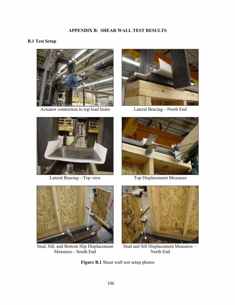
106
APPENDIX B: SHEAR WALL TEST RESULTS
B.1 Test Setup
Actuator connection to top load beam Lateral Bracing—North End
Lateral Bracing—Top view Top Displacement Measures
Stud, Sill, and Bottom Slip Displacement
Measures—South End Stud and Sill Displacement Measures—
North End
Figure B.1 Shear wall test setup photos
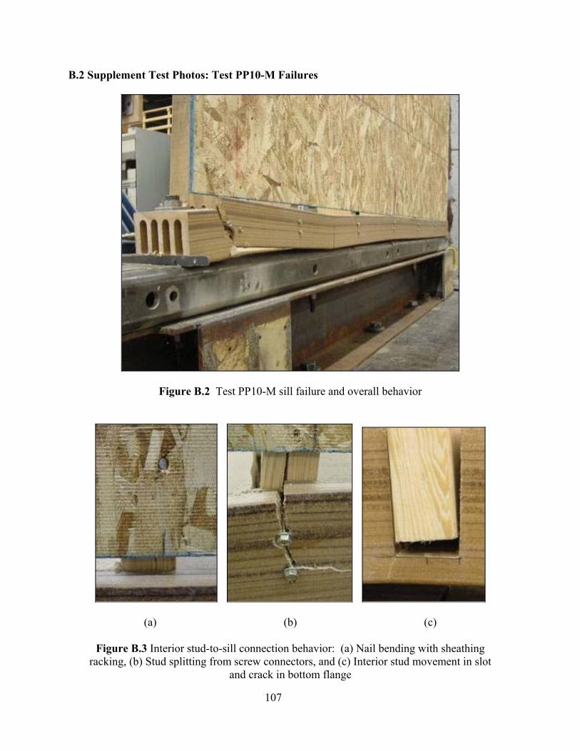
107
B.2 Supplement Test Photos: Test PP10-M Failures
Figure B.2 Test PP10-M sill failure and overall behavior
(a)
(b)
(c)
Figure B.3 Interior stud-to-sill connection behavior: (a) Nail bending with sheathing racking, (b) Stud splitting from screw connectors, and (c) Interior stud movement in slot
and crack in bottom flange
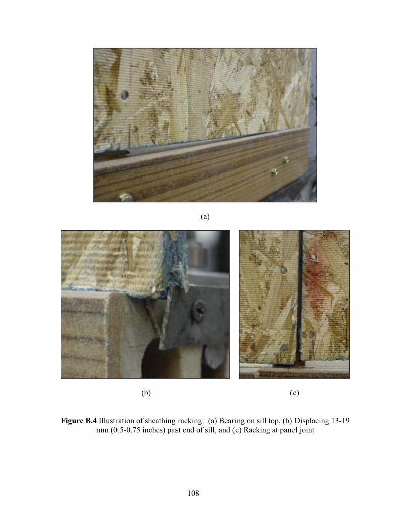
108
(a)
(b)
(c)
Figure B.4 Illustration of sheathing racking: (a) Bearing on sill top, (b) Displacing 13-19
mm (0.5-0.75 inches) past end of sill, and (c) Racking at panel joint
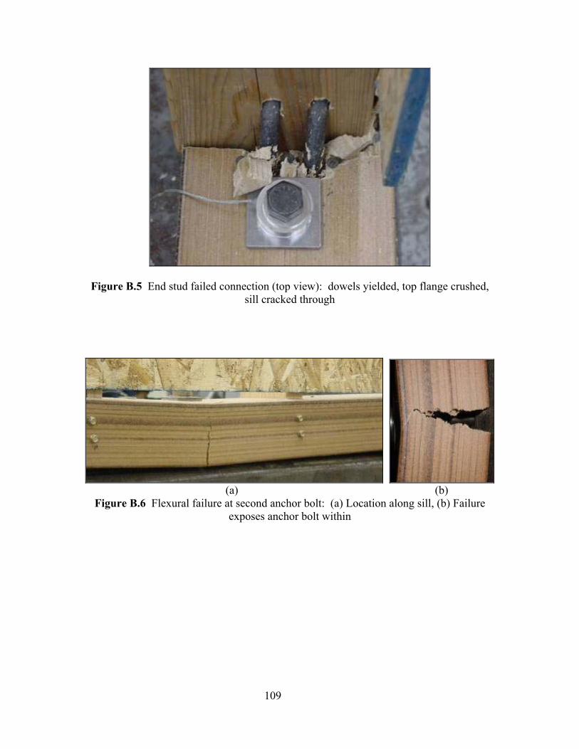
109
Figure B.5 End stud failed connection (top view): dowels yielded, top flange crushed, sill cracked through
(a) (b)
Figure B.6 Flexural failure at second anchor bolt: (a) Location along sill, (b) Failure exposes anchor bolt within
110
B.3 Cyclic Test Data
Presented for each cyclic test are summarized test parameters, hysteresis curves, time
histories, and energy and damping calculations. Test parameters are summarized in Tables B.1,
B.3, B.5, B.7, B.9, B.11, B.13, and B.15, based on averages from positive and negative response
and EEEP parameters. Hysteresis curves include full data collected and overlaying response
curves represent behavior up until failure (80% peak loads). Time histories are presented for
each test, representing displacements induced by the hydraulic cylinder. Finally, damping ratios
are calculated for each cycle (Tables B.2, B.4, B.6, B.8, B.10, B.12, B.14, B.16), based on the
strain energy and work done per cycle. The sum of the work done approximates energy
dissipation in cyclic loops up until the point of failure. Hysteresis and strain energy have
negative values for some early cycles due to measurement accuracy at these small displacements.
Contributions to area totals are negligible.
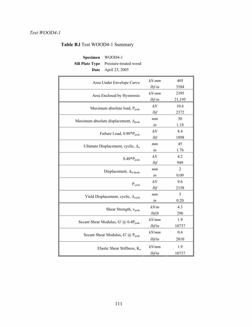
111
Test WOOD4-1
Table B.l Test WOOD4-1 Summary
Specimen WOOD4-1 Sill Plate Type Pressure-treated wood
Date April 23, 2005
kN-mm 405 Area Under Envelope Curve lbf-in 3584
kN-mm 2395 Area Enclosed by Hysteresis lbf-in 21,195
kN 10.6 Maximum absolute load, Ppeak lbf 2372 mm 30 Maximum absolute displacement, ∆peak in 1.18 kN 8.4 Failure Load, 0.80*Ppeak lbf 1898 mm 45 Ultimate Displacement, cyclic, ∆u in 1.76 kN 4.2 0.40*Ppeak lbf 949 mm 2 Displacement, ∆0.4peak in 0.09 kN 9.6 Pyield lbf 2158 mm 5 Yield Displacement, cyclic, ∆yield in 0.20
kN/m 4.3 Shear Strength, vpeak lbf/ft 296
kN/mm 1.9 Secant Shear Modulus, G' @ 0.4Ppeak lbf/in 10737
kN/mm 0.4 Secant Shear Modulus, G' @ Ppeak lbf/in 2010
kN/mm 1.9 Elastic Shear Stiffness, Ke lbf/in 10737
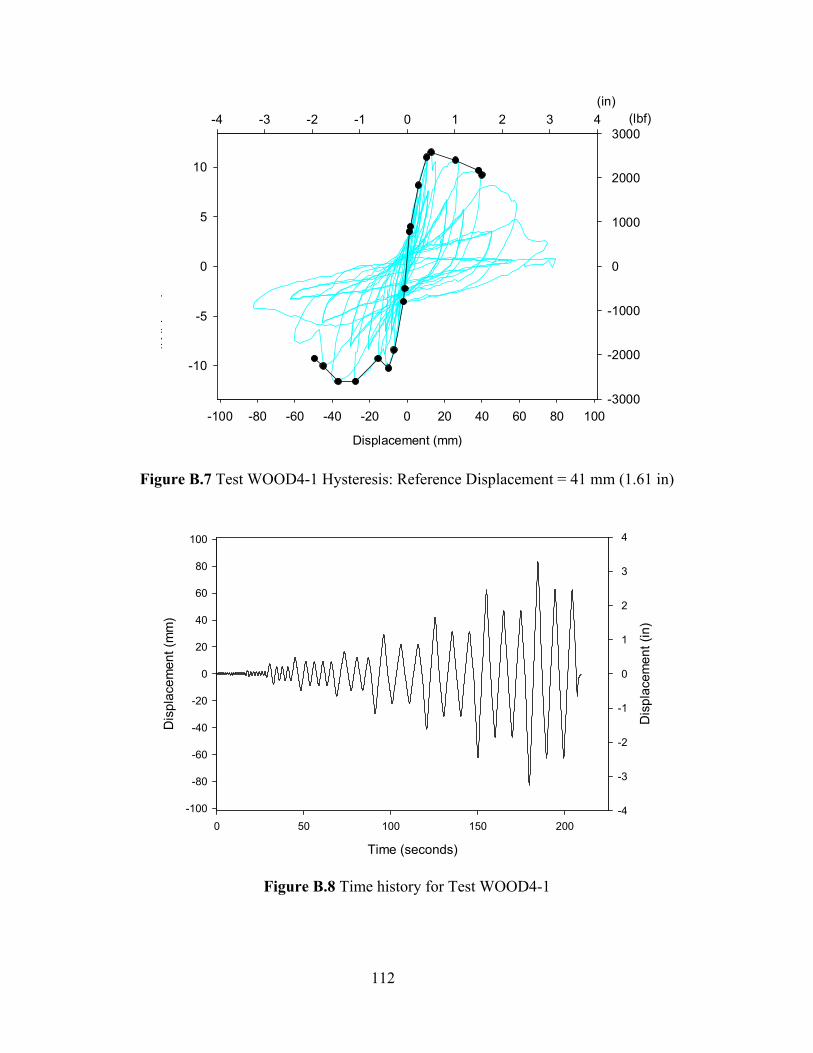
112
Displacement (mm)
-100 -80 -60 -40 -20 0 20 40 60 80 100
Ld
(kN)
-10
-5
0
5
10
Envelope CurveHysteresis
(in)-4 -3 -2 -1 0 1 2 3 4 (lbf)
-3000
-2000
-1000
0
1000
2000
3000
Figure B.7 Test WOOD4-1 Hysteresis: Reference Displacement = 41 mm (1.61 in)
Time (seconds)
0 50 100 150 200
Dis
plac
emen
t (m
m)
-100
-80
-60
-40
-20
0
20
40
60
80
100
Dis
plac
emen
t (in
)
-4
-3
-2
-1
0
1
2
3
4
Figure B.8 Time history for Test WOOD4-1
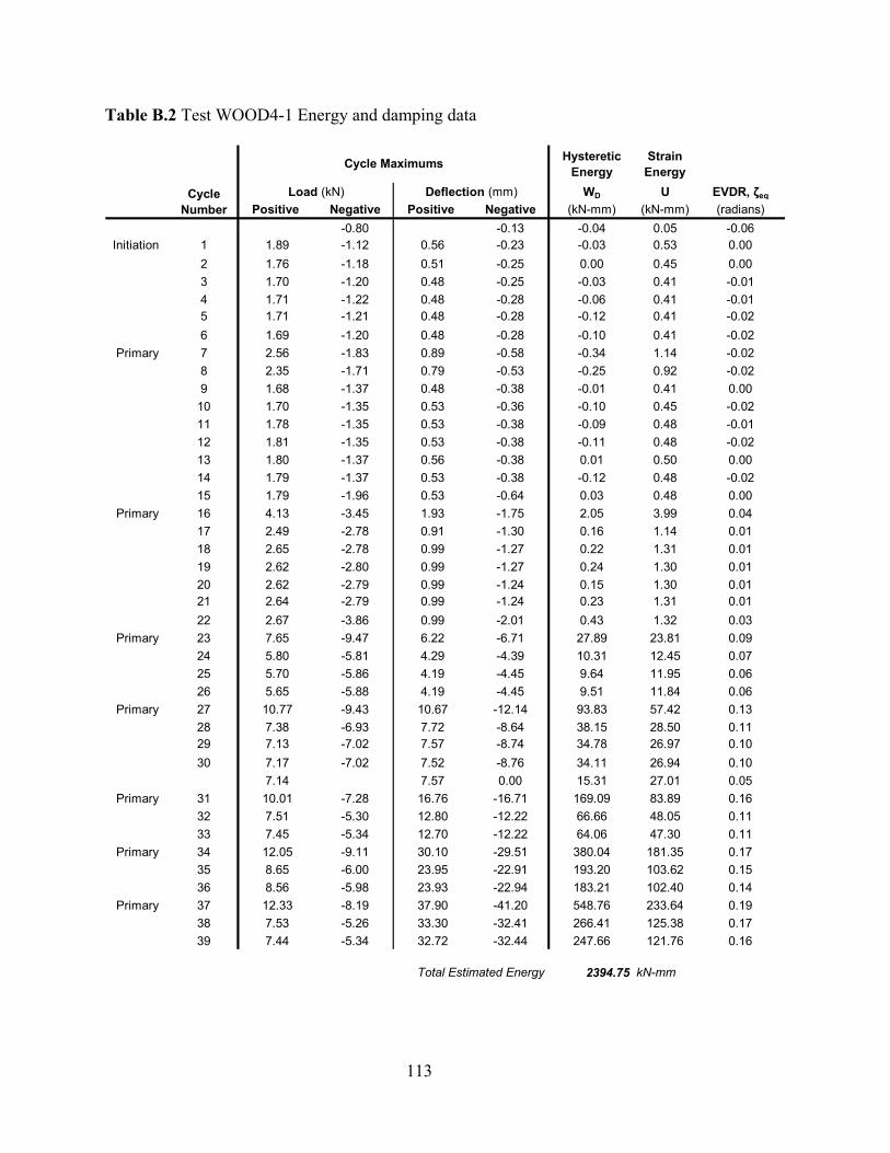
113
Table B.2 Test WOOD4-1 Energy and damping data
Hysteretic Energy
Strain Energy
WD U EVDR, ζeq
Positive Negative Positive Negative (kN-mm) (kN-mm) (radians)-0.80 -0.13 -0.04 0.05 -0.06
Initiation 1 1.89 -1.12 0.56 -0.23 -0.03 0.53 0.002 1.76 -1.18 0.51 -0.25 0.00 0.45 0.003 1.70 -1.20 0.48 -0.25 -0.03 0.41 -0.014 1.71 -1.22 0.48 -0.28 -0.06 0.41 -0.015 1.71 -1.21 0.48 -0.28 -0.12 0.41 -0.026 1.69 -1.20 0.48 -0.28 -0.10 0.41 -0.02
Primary 7 2.56 -1.83 0.89 -0.58 -0.34 1.14 -0.028 2.35 -1.71 0.79 -0.53 -0.25 0.92 -0.029 1.68 -1.37 0.48 -0.38 -0.01 0.41 0.00
10 1.70 -1.35 0.53 -0.36 -0.10 0.45 -0.0211 1.78 -1.35 0.53 -0.38 -0.09 0.48 -0.0112 1.81 -1.35 0.53 -0.38 -0.11 0.48 -0.0213 1.80 -1.37 0.56 -0.38 0.01 0.50 0.0014 1.79 -1.37 0.53 -0.38 -0.12 0.48 -0.0215 1.79 -1.96 0.53 -0.64 0.03 0.48 0.00
Primary 16 4.13 -3.45 1.93 -1.75 2.05 3.99 0.0417 2.49 -2.78 0.91 -1.30 0.16 1.14 0.0118 2.65 -2.78 0.99 -1.27 0.22 1.31 0.0119 2.62 -2.80 0.99 -1.27 0.24 1.30 0.0120 2.62 -2.79 0.99 -1.24 0.15 1.30 0.0121 2.64 -2.79 0.99 -1.24 0.23 1.31 0.0122 2.67 -3.86 0.99 -2.01 0.43 1.32 0.03
Primary 23 7.65 -9.47 6.22 -6.71 27.89 23.81 0.0924 5.80 -5.81 4.29 -4.39 10.31 12.45 0.0725 5.70 -5.86 4.19 -4.45 9.64 11.95 0.0626 5.65 -5.88 4.19 -4.45 9.51 11.84 0.06
Primary 27 10.77 -9.43 10.67 -12.14 93.83 57.42 0.1328 7.38 -6.93 7.72 -8.64 38.15 28.50 0.1129 7.13 -7.02 7.57 -8.74 34.78 26.97 0.1030 7.17 -7.02 7.52 -8.76 34.11 26.94 0.10
7.14 7.57 0.00 15.31 27.01 0.05Primary 31 10.01 -7.28 16.76 -16.71 169.09 83.89 0.16
32 7.51 -5.30 12.80 -12.22 66.66 48.05 0.1133 7.45 -5.34 12.70 -12.22 64.06 47.30 0.11
Primary 34 12.05 -9.11 30.10 -29.51 380.04 181.35 0.1735 8.65 -6.00 23.95 -22.91 193.20 103.62 0.1536 8.56 -5.98 23.93 -22.94 183.21 102.40 0.14
Primary 37 12.33 -8.19 37.90 -41.20 548.76 233.64 0.1938 7.53 -5.26 33.30 -32.41 266.41 125.38 0.1739 7.44 -5.34 32.72 -32.44 247.66 121.76 0.16
Total Estimated Energy 2394.75 kN-mm
Cycle Maximums
Cycle Number
Load (kN) Deflection (mm)
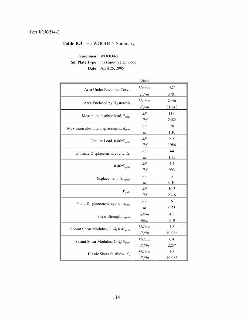
114
Test WOOD4-2
Table B.3 Test WOOD4-2 Summary
Specimen WOOD4-2 Sill Plate Type Pressure-treated wood
Date April 25, 2005
Units
kN-mm 427 Area Under Envelope Curve lbf-in 3781
kN-mm 2446 Area Enclosed by Hysteresis lbf-in 21,648
kN 11.0 Maximum absolute load, Ppeak lbf 2482 mm 28 Maximum absolute displacement, ∆peak in 1.10 kN 8.8 Failure Load, 0.80*Ppeak lbf 1986 mm 44 Ultimate Displacement, cyclic, ∆u in 1.75 kN 4.4 0.40*Ppeak lbf 993 mm 3 Displacement, ∆0.4peak in 0.10 kN 10.3 Pyield lbf 2316 mm 6 Yield Displacement, cyclic, ∆yield in 0.23
kN/m 4.5 Shear Strength, vpeak lbf/ft 310
kN/mm 1.8 Secant Shear Modulus, G' @ 0.4Ppeak lbf/in 10,086
kN/mm 0.4 Secant Shear Modulus, G' @ Ppeak lbf/in 2257
kN/mm 1.8 Elastic Shear Stiffness, Ke lbf/in 10,086
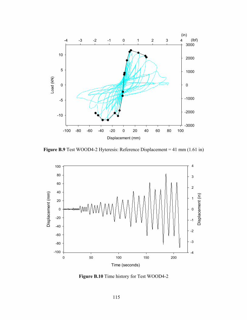
115
Displacement (mm)
-100 -80 -60 -40 -20 0 20 40 60 80 100
Load
(kN
)
-10
-5
0
5
10
Envelope CurveHysteresis
(in)-4 -3 -2 -1 0 1 2 3 4 (lbf)
-3000
-2000
-1000
0
1000
2000
3000
Figure B.9 Test WOOD4-2 Hyteresis: Reference Displacement = 41 mm (1.61 in)
Time (seconds)
0 50 100 150 200
Dis
plac
emen
t (m
m)
-100
-80
-60
-40
-20
0
20
40
60
80
100
Dis
plac
emen
t (in
)
-4
-3
-2
-1
0
1
2
3
4
Figure B.10 Time history for Test WOOD4-2
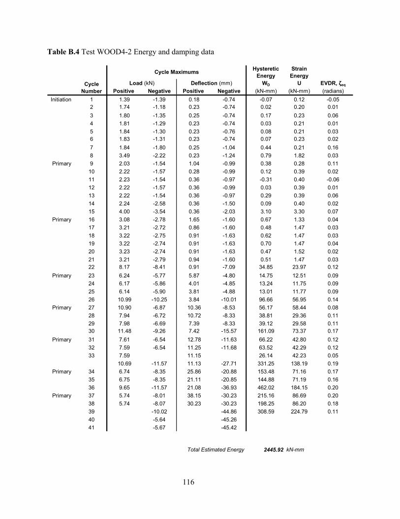
116
Table B.4 Test WOOD4-2 Energy and damping data
Hysteretic Energy
Strain Energy
WD U EVDR, ζeq
Positive Negative Positive Negative (kN-mm) (kN-mm) (radians)Initiation 1 1.39 -1.39 0.18 -0.74 -0.07 0.12 -0.05
2 1.74 -1.18 0.23 -0.74 0.02 0.20 0.013 1.80 -1.35 0.25 -0.74 0.17 0.23 0.064 1.81 -1.29 0.23 -0.74 0.03 0.21 0.015 1.84 -1.30 0.23 -0.76 0.08 0.21 0.036 1.83 -1.31 0.23 -0.74 0.07 0.23 0.027 1.84 -1.80 0.25 -1.04 0.44 0.21 0.168 3.49 -2.22 0.23 -1.24 0.79 1.82 0.03
Primary 9 2.03 -1.54 1.04 -0.99 0.38 0.28 0.1110 2.22 -1.57 0.28 -0.99 0.12 0.39 0.0211 2.23 -1.54 0.36 -0.97 -0.31 0.40 -0.0612 2.22 -1.57 0.36 -0.99 0.03 0.39 0.0113 2.22 -1.54 0.36 -0.97 0.29 0.39 0.0614 2.24 -2.58 0.36 -1.50 0.09 0.40 0.0215 4.00 -3.54 0.36 -2.03 3.10 3.30 0.07
Primary 16 3.08 -2.78 1.65 -1.60 0.67 1.33 0.0417 3.21 -2.72 0.86 -1.60 0.48 1.47 0.0318 3.22 -2.75 0.91 -1.63 0.62 1.47 0.0319 3.22 -2.74 0.91 -1.63 0.70 1.47 0.0420 3.23 -2.74 0.91 -1.63 0.47 1.52 0.0221 3.21 -2.79 0.94 -1.60 0.51 1.47 0.0322 8.17 -8.41 0.91 -7.09 34.85 23.97 0.12
Primary 23 6.24 -5.77 5.87 -4.80 14.75 12.51 0.0924 6.17 -5.86 4.01 -4.85 13.24 11.75 0.0925 6.14 -5.90 3.81 -4.88 13.01 11.77 0.0926 10.99 -10.25 3.84 -10.01 96.66 56.95 0.14
Primary 27 10.90 -6.87 10.36 -8.53 56.17 58.44 0.0828 7.94 -6.72 10.72 -8.33 38.81 29.36 0.1129 7.98 -6.69 7.39 -8.33 39.12 29.58 0.1130 11.48 -9.26 7.42 -15.57 161.09 73.37 0.17
Primary 31 7.61 -6.54 12.78 -11.63 66.22 42.80 0.1232 7.59 -6.54 11.25 -11.68 63.52 42.29 0.1233 7.59 11.15 26.14 42.23 0.05
10.69 -11.57 11.13 -27.71 331.25 138.19 0.19Primary 34 6.74 -8.35 25.86 -20.88 153.48 71.16 0.17
35 6.75 -8.35 21.11 -20.85 144.88 71.19 0.1636 9.65 -11.57 21.08 -36.93 462.02 184.15 0.20
Primary 37 5.74 -8.01 38.15 -30.23 215.16 86.69 0.2038 5.74 -8.07 30.23 -30.23 198.25 86.20 0.1839 -10.02 -44.86 308.59 224.79 0.1140 -5.64 -45.2641 -5.67 -45.42
Total Estimated Energy 2445.92 kN-mm
Cycle Maximums
Cycle Number
Load (kN) Deflection (mm)
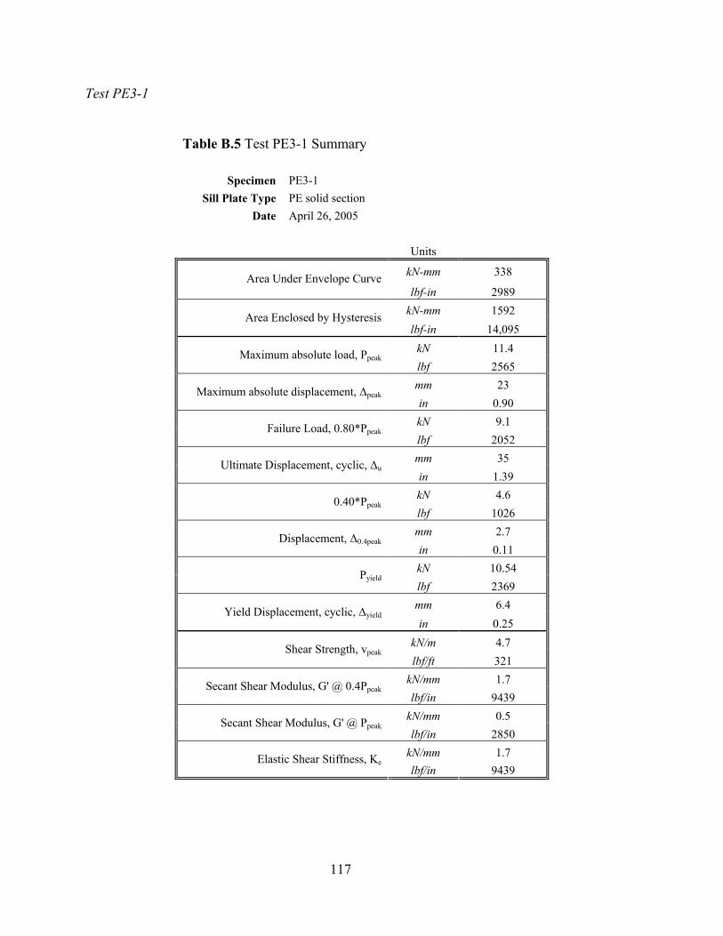
117
Test PE3-1
Table B.5 Test PE3-1 Summary
Specimen PE3-1 Sill Plate Type PE solid section
Date April 26, 2005 Units
kN-mm 338 Area Under Envelope Curve lbf-in 2989
kN-mm 1592 Area Enclosed by Hysteresis lbf-in 14,095
kN 11.4 Maximum absolute load, Ppeak lbf 2565 mm 23 Maximum absolute displacement, ∆peak in 0.90 kN 9.1 Failure Load, 0.80*Ppeak lbf 2052 mm 35 Ultimate Displacement, cyclic, ∆u in 1.39 kN 4.6 0.40*Ppeak lbf 1026 mm 2.7 Displacement, ∆0.4peak in 0.11 kN 10.54 Pyield lbf 2369 mm 6.4 Yield Displacement, cyclic, ∆yield in 0.25
kN/m 4.7 Shear Strength, vpeak lbf/ft 321
kN/mm 1.7 Secant Shear Modulus, G' @ 0.4Ppeak lbf/in 9439
kN/mm 0.5 Secant Shear Modulus, G' @ Ppeak lbf/in 2850
kN/mm 1.7 Elastic Shear Stiffness, Ke lbf/in 9439
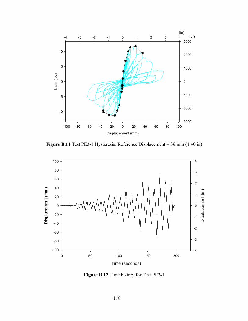
118
Displacement (mm)
-100 -80 -60 -40 -20 0 20 40 60 80 100
Load
(kN
)
-10
-5
0
5
10
(in)-4 -3 -2 -1 0 1 2 3 4 (lbf)
-3000
-2000
-1000
0
1000
2000
3000
Figure B.11 Test PE3-1 Hysteresis: Reference Displacement = 36 mm (1.40 in)
Time (seconds)
0 50 100 150 200
Dis
plac
emen
t (m
m)
-100
-80
-60
-40
-20
0
20
40
60
80
100
Dis
plac
emen
t (in
)
-4
-3
-2
-1
0
1
2
3
4
Figure B.12 Time history for Test PE3-1
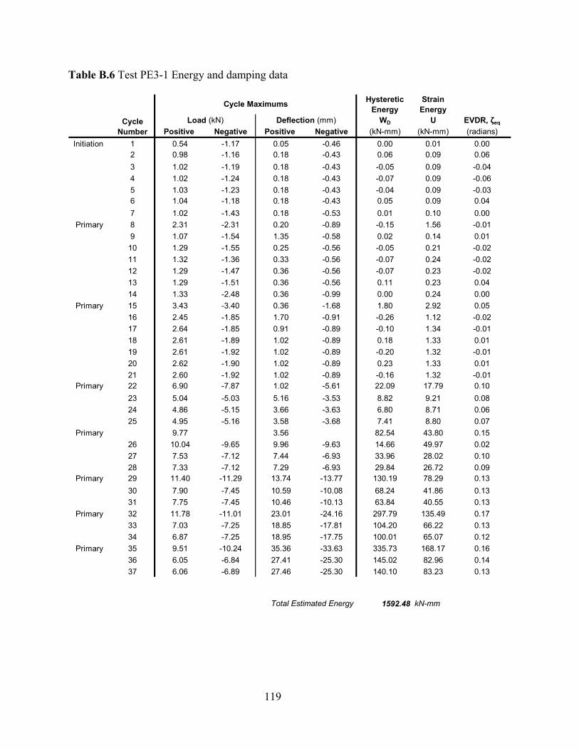
119
Table B.6 Test PE3-1 Energy and damping data
Hysteretic Energy
Strain Energy
WD U EVDR, ζeq
Positive Negative Positive Negative (kN-mm) (kN-mm) (radians)Initiation 1 0.54 -1.17 0.05 -0.46 0.00 0.01 0.00
2 0.98 -1.16 0.18 -0.43 0.06 0.09 0.063 1.02 -1.19 0.18 -0.43 -0.05 0.09 -0.044 1.02 -1.24 0.18 -0.43 -0.07 0.09 -0.065 1.03 -1.23 0.18 -0.43 -0.04 0.09 -0.036 1.04 -1.18 0.18 -0.43 0.05 0.09 0.047 1.02 -1.43 0.18 -0.53 0.01 0.10 0.00
Primary 8 2.31 -2.31 0.20 -0.89 -0.15 1.56 -0.019 1.07 -1.54 1.35 -0.58 0.02 0.14 0.01
10 1.29 -1.55 0.25 -0.56 -0.05 0.21 -0.0211 1.32 -1.36 0.33 -0.56 -0.07 0.24 -0.0212 1.29 -1.47 0.36 -0.56 -0.07 0.23 -0.0213 1.29 -1.51 0.36 -0.56 0.11 0.23 0.0414 1.33 -2.48 0.36 -0.99 0.00 0.24 0.00
Primary 15 3.43 -3.40 0.36 -1.68 1.80 2.92 0.0516 2.45 -1.85 1.70 -0.91 -0.26 1.12 -0.0217 2.64 -1.85 0.91 -0.89 -0.10 1.34 -0.0118 2.61 -1.89 1.02 -0.89 0.18 1.33 0.0119 2.61 -1.92 1.02 -0.89 -0.20 1.32 -0.0120 2.62 -1.90 1.02 -0.89 0.23 1.33 0.0121 2.60 -1.92 1.02 -0.89 -0.16 1.32 -0.01
Primary 22 6.90 -7.87 1.02 -5.61 22.09 17.79 0.1023 5.04 -5.03 5.16 -3.53 8.82 9.21 0.0824 4.86 -5.15 3.66 -3.63 6.80 8.71 0.0625 4.95 -5.16 3.58 -3.68 7.41 8.80 0.07
Primary 9.77 3.56 82.54 43.80 0.1526 10.04 -9.65 9.96 -9.63 14.66 49.97 0.0227 7.53 -7.12 7.44 -6.93 33.96 28.02 0.1028 7.33 -7.12 7.29 -6.93 29.84 26.72 0.09
Primary 29 11.40 -11.29 13.74 -13.77 130.19 78.29 0.1330 7.90 -7.45 10.59 -10.08 68.24 41.86 0.1331 7.75 -7.45 10.46 -10.13 63.84 40.55 0.13
Primary 32 11.78 -11.01 23.01 -24.16 297.79 135.49 0.1733 7.03 -7.25 18.85 -17.81 104.20 66.22 0.1334 6.87 -7.25 18.95 -17.75 100.01 65.07 0.12
Primary 35 9.51 -10.24 35.36 -33.63 335.73 168.17 0.1636 6.05 -6.84 27.41 -25.30 145.02 82.96 0.1437 6.06 -6.89 27.46 -25.30 140.10 83.23 0.13
Total Estimated Energy 1592.48 kN-mm
Cycle Maximums
Cycle Number
Load (kN) Deflection (mm)

120
Test PE3-2
Table B.7 Test PE3-2 Summary
Specimen PE3-2 Sill Plate Type PE solid section
Date April 27, 2005 Units
kN-mm 354 Area Under Envelope Curve lbf-in 3129
kN-mm 1611 Area Enclosed by Hysteresis lbf-in 14,258
kN 12.3 Maximum absolute load, Ppeak lbf 2770 mm 17 Maximum absolute displacement, ∆peak in 0.66 kN 9.9 Failure Load, 0.80*Ppeak lbf 2216 mm 36 Ultimate Displacement, cyclic, ∆u in 1.40 kN 5.0 0.40*Ppeak lbf 1108 mm 4 Displacement, ∆0.4peak in 0.15 kN 11.3 Pyield lbf 2543 mm 9 Yield Displacement, cyclic, ∆yield in 0.34
kN/m 5.1 Shear Strength, vpeak lbf/ft 346
kN/mm 1.3 Secant Shear Modulus, G' @ 0.4Ppeak lbf/in 7575
kN/mm 0.7 Secant Shear Modulus, G' @ Ppeak lbf/in 4196
kN/mm 1.3 Elastic Shear Stiffness, Ke lbf/in 7575
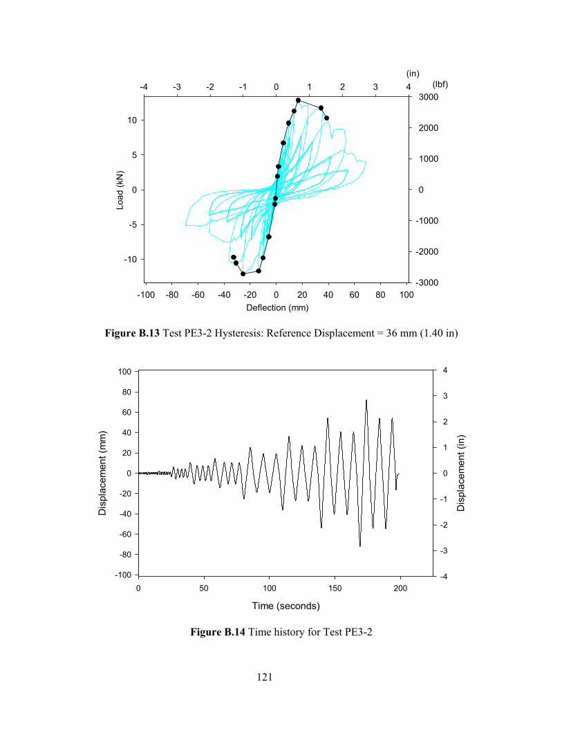
121
Deflection (mm)-100 -80 -60 -40 -20 0 20 40 60 80 100
Load
(kN
)
-10
-5
0
5
10
(in)-4 -3 -2 -1 0 1 2 3 4 (lbf)
-3000
-2000
-1000
0
1000
2000
3000
Figure B.13 Test PE3-2 Hysteresis: Reference Displacement = 36 mm (1.40 in)
Time (seconds)
0 50 100 150 200
Dis
plac
emen
t (m
m)
-100
-80
-60
-40
-20
0
20
40
60
80
100
Dis
plac
emen
t (in
)
-4
-3
-2
-1
0
1
2
3
4
Figure B.14 Time history for Test PE3-2
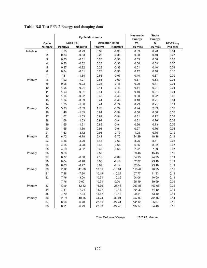
122
Table B.8 Test PE3-2 Energy and damping data
Hysteretic Energy
Strain Energy
WD U EVDR, ζeq
Positive Negative Positive Negative (kN-mm) (kN-mm) (radians)Initiation 1 1.05 -0.73 0.38 -0.30 0.09 0.20 0.04
2 0.83 -0.83 0.23 -0.36 0.08 0.10 0.073 0.83 -0.81 0.20 -0.38 0.03 0.08 0.034 0.83 -0.82 0.23 -0.38 0.06 0.09 0.055 0.87 -0.82 0.23 -0.38 0.01 0.10 0.016 0.84 -0.81 0.23 -0.38 0.12 0.10 0.107 1.31 -1.64 0.56 -0.97 0.40 0.37 0.09
Primary 8 1.92 -1.27 0.86 -0.69 0.37 0.83 0.049 0.96 -0.93 0.36 -0.46 0.09 0.17 0.04
10 1.05 -0.91 0.41 -0.43 0.11 0.21 0.0411 1.03 -0.91 0.41 -0.43 0.10 0.21 0.0412 1.04 -0.92 0.43 -0.46 0.00 0.22 0.0013 1.04 -0.89 0.41 -0.46 0.10 0.21 0.0414 1.05 -1.36 0.41 -0.74 0.29 0.21 0.11
Primary 15 3.33 -2.09 1.70 -1.24 0.94 2.83 0.0316 1.46 -1.65 0.81 -0.94 0.56 0.60 0.0717 1.62 -1.63 0.89 -0.94 0.31 0.72 0.0318 1.66 -1.63 0.91 -0.91 0.31 0.76 0.0319 1.65 -1.61 0.89 -0.91 0.56 0.73 0.0620 1.65 -1.60 0.91 -0.91 0.27 0.76 0.0321 1.63 -3.72 0.91 -2.79 1.08 0.75 0.12
Primary 22 6.72 -6.78 5.41 -5.72 24.39 18.18 0.1123 4.66 -4.29 3.48 -3.63 8.25 8.11 0.0824 4.65 -4.28 3.45 -3.68 6.86 8.02 0.0725 4.59 -4.32 3.48 -3.68 7.22 7.99 0.07
Primary 26 9.56 9.50 69.46 45.43 0.1227 6.77 -6.30 7.16 -7.09 34.93 24.25 0.1128 6.64 -6.48 6.96 -7.16 32.87 23.10 0.1129 6.63 -6.47 6.99 -7.14 32.64 23.16 0.11
Primary 30 11.30 -11.68 13.61 -13.61 113.44 76.95 0.1231 7.88 -7.90 10.49 -10.24 57.77 41.33 0.1132 7.76 -8.00 10.31 -10.26 54.06 40.00 0.11
7.76 0.00 10.31 0.00 25.49 39.99 0.05Primary 33 12.84 -12.12 16.76 -25.48 297.86 107.66 0.22
34 7.81 -7.24 18.97 -19.18 104.39 74.10 0.1135 7.79 -7.34 18.87 -19.18 99.21 73.49 0.11
Primary 36 11.74 -10.55 34.24 -30.91 357.00 201.02 0.1437 6.96 -6.78 27.51 -27.41 141.65 95.67 0.1238 6.91 -6.79 27.33 -27.43 137.53 94.48 0.12
Total Estimated Energy 1610.90 kN-mm
Cycle Maximums
Cycle Number
Load (kN) Deflection (mm)
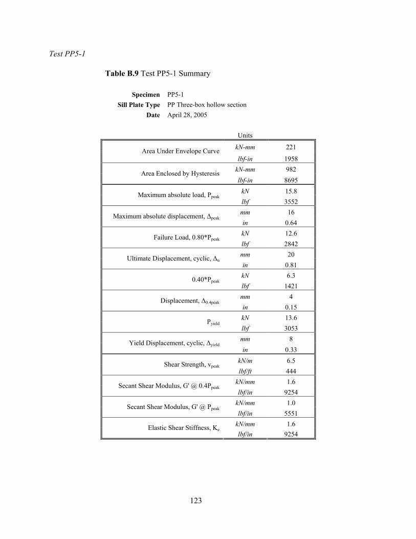
123
Test PP5-1
Table B.9 Test PP5-1 Summary
Specimen PP5-1 Sill Plate Type PP Three-box hollow section
Date April 28, 2005 Units
kN-mm 221 Area Under Envelope Curve lbf-in 1958
kN-mm 982 Area Enclosed by Hysteresis lbf-in 8695
kN 15.8 Maximum absolute load, Ppeak lbf 3552 mm 16 Maximum absolute displacement, ∆peak in 0.64 kN 12.6 Failure Load, 0.80*Ppeak lbf 2842 mm 20 Ultimate Displacement, cyclic, ∆u in 0.81 kN 6.3 0.40*Ppeak lbf 1421 mm 4 Displacement, ∆0.4peak in 0.15 kN 13.6 Pyield lbf 3053 mm 8 Yield Displacement, cyclic, ∆yield in 0.33
kN/m 6.5 Shear Strength, vpeak lbf/ft 444
kN/mm 1.6 Secant Shear Modulus, G' @ 0.4Ppeak lbf/in 9254
kN/mm 1.0 Secant Shear Modulus, G' @ Ppeak lbf/in 5551
kN/mm 1.6 Elastic Shear Stiffness, Ke lbf/in 9254
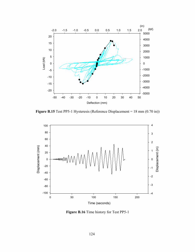
124
Deflection (mm)
-50 -40 -30 -20 -10 0 10 20 30 40 50
Load
(kN
)
-20
-15
-10
-5
0
5
10
15
20
(in)-2.0 -1.5 -1.0 -0.5 0.0 0.5 1.0 1.5 2.0 (lbf)
-5000
-4000
-3000
-2000
-1000
0
1000
2000
3000
4000
5000
Figure B.15 Test PP5-1 Hysteresis (Reference Displacement = 18 mm (0.70 in))
Time (seconds)
0 50 100 150 200
Dis
plac
emen
t (m
m)
-100
-80
-60
-40
-20
0
20
40
60
80
100
Dis
plac
emen
t (in
)
-4
-3
-2
-1
0
1
2
3
4
Figure B.16 Time history for Test PP5-1
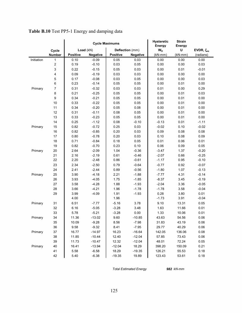
125
Table B.10 Test PP5-1 Energy and damping data
Hysteretic Energy
Strain Energy
WD U EVDR, ζeq
Positive Negative Positive Negative (kN-mm) (kN-mm) (radians)Initiation 1 0.10 -0.09 0.05 0.03 0.00 0.00 0.00
2 0.19 -0.10 0.03 0.05 0.00 0.00 0.033 0.22 -0.15 0.05 0.03 0.00 0.01 -0.014 0.09 -0.19 0.03 0.03 0.00 0.00 0.005 0.17 -0.08 0.03 0.05 0.00 0.00 0.036 0.23 -0.14 0.05 0.05 0.00 0.01 0.00
Primary 7 0.31 -0.32 0.03 0.03 0.01 0.00 0.298 0.21 -0.25 0.05 0.05 0.00 0.01 0.039 0.34 -0.21 0.05 0.05 0.00 0.01 0.00
10 0.33 -0.22 0.05 0.05 0.00 0.01 0.0011 0.34 -0.20 0.05 0.08 0.00 0.01 0.0012 0.31 -0.11 0.08 0.05 0.00 0.01 0.0013 0.33 -0.23 0.05 0.05 0.00 0.01 0.0014 0.25 -1.12 0.08 -0.10 -0.13 0.01 -1.11
Primary 15 0.82 -0.72 0.25 0.03 -0.02 0.10 -0.0216 0.82 -0.85 0.20 0.03 0.09 0.08 0.0817 0.80 -0.78 0.20 0.03 0.10 0.08 0.0918 0.71 -0.84 0.18 0.05 0.01 0.06 0.0119 0.82 -0.70 0.23 0.10 0.06 0.09 0.05
Primary 20 2.64 -2.09 1.04 -0.36 -3.47 1.37 -0.2021 2.16 -2.19 0.61 -0.46 -2.07 0.66 -0.2522 2.20 -2.48 0.86 -0.61 -1.17 0.95 -0.1023 2.34 -2.50 0.79 -0.64 -0.77 0.92 -0.0724 2.41 -2.44 0.89 -0.56 -1.80 1.07 -0.13
Primary 25 3.90 -4.18 2.21 -1.88 -7.77 4.31 -0.1426 3.93 -4.05 1.75 -1.85 -8.37 3.45 -0.1927 3.58 -4.28 1.88 -1.93 -2.04 3.36 -0.0528 3.66 -4.21 1.96 -1.78 -1.78 3.58 -0.0429 3.99 -4.09 1.91 -1.93 0.28 3.80 0.01
4.00 1.96 -1.73 3.91 -0.04Primary 31 6.51 -7.77 -5.16 3.78 9.10 13.31 0.05
32 6.16 -5.05 -3.28 3.48 1.63 11.66 0.0133 5.78 -5.21 -3.28 0.00 1.33 10.06 0.01
Primary 34 11.36 -13.02 9.60 -10.85 43.63 54.56 0.0635 10.09 -9.28 8.56 -7.98 31.83 43.19 0.0636 9.58 -9.32 8.41 -7.95 29.77 40.29 0.06
Primary 37 16.77 -14.97 16.23 -16.64 142.05 136.06 0.0838 11.85 -10.44 12.40 -12.04 57.85 73.43 0.0639 11.73 -10.47 12.32 -12.04 48.01 72.24 0.05
Primary 40 16.41 -13.94 -12.04 18.29 398.20 150.09 0.2141 5.58 -6.58 18.29 -19.35 126.21 55.53 0.1842 5.40 -6.38 -19.35 19.89 123.43 53.61 0.18
Total Estimated Energy 982 kN-mm
Cycle Maximums
Cycle Number
Load (kN) Deflection (mm)
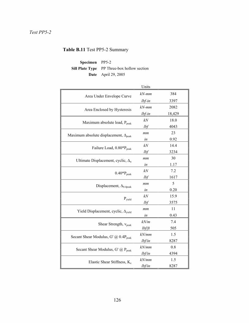
126
Test PP5-2
Table B.11 Test PP5-2 Summary
Specimen PP5-2
Sill Plate Type PP Three-box hollow section Date April 29, 2005
Units
kN-mm 384 Area Under Envelope Curve lbf-in 3397
kN-mm 2082 Area Enclosed by Hysteresis lbf-in 18,429
kN 18.0 Maximum absolute load, Ppeak lbf 4043 mm 23 Maximum absolute displacement, ∆peak in 0.92 kN 14.4 Failure Load, 0.80*Ppeak lbf 3234 mm 30 Ultimate Displacement, cyclic, ∆u in 1.17 kN 7.2 0.40*Ppeak lbf 1617 mm 5 Displacement, ∆0.4peak in 0.20 kN 15.9 Pyield lbf 3575 mm 11 Yield Displacement, cyclic, ∆yield in 0.43
kN/m 7.4 Shear Strength, vpeak lbf/ft 505
kN/mm 1.5 Secant Shear Modulus, G' @ 0.4Ppeak lbf/in 8287
kN/mm 0.8 Secant Shear Modulus, G' @ Ppeak lbf/in 4394
kN/mm 1.5 Elastic Shear Stiffness, Ke lbf/in 8287
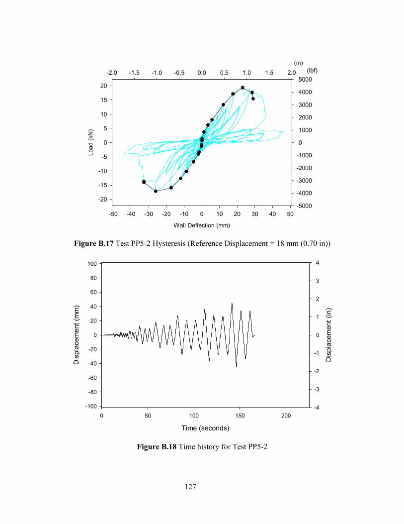
127
Wall Deflection (mm)
-50 -40 -30 -20 -10 0 10 20 30 40 50
Load
(kN
)
-20
-15
-10
-5
0
5
10
15
20
(in)-2.0 -1.5 -1.0 -0.5 0.0 0.5 1.0 1.5 2.0 (lbf)
-5000
-4000
-3000
-2000
-1000
0
1000
2000
3000
4000
5000
Figure B.17 Test PP5-2 Hysteresis (Reference Displacement = 18 mm (0.70 in))
Time (seconds)
0 50 100 150 200
Dis
plac
emen
t (m
m)
-100
-80
-60
-40
-20
0
20
40
60
80
100
Dis
plac
emen
t (in
)
-4
-3
-2
-1
0
1
2
3
4
Figure B.18 Time history for Test PP5-2
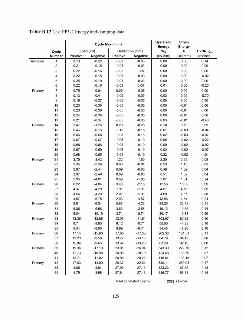
128
Table B.12 Test PP5-2 Energy and damping data
Hysteretic Energy
Strain Energy
WD U EVDR, ζeq
Positive Negative Positive Negative (kN-mm) (kN-mm) (radians)Initiation 1 0.13 -0.22 -0.03 -0.03 0.00 0.00 0.14
2 0.21 -0.15 -0.03 -0.03 0.00 0.00 0.003 0.22 -0.16 -0.03 0.00 0.00 0.00 0.004 0.22 -0.15 -0.03 -0.03 0.00 0.00 -0.025 0.25 -0.19 -0.03 -0.03 0.00 0.00 0.006 0.22 -0.16 -0.03 0.00 0.01 0.00 -0.20
Primary 7 0.75 -0.64 0.00 -0.05 0.00 0.00 0.008 0.13 -0.41 -0.05 -0.05 0.03 0.00 -0.709 0.19 -0.37 -0.05 -0.05 0.00 0.00 0.00
10 0.23 -0.36 -0.05 -0.05 0.00 -0.01 0.0011 0.23 -0.36 -0.05 -0.05 0.00 -0.01 0.0012 0.24 -0.36 -0.05 -0.05 0.00 -0.01 0.0013 0.21 -0.37 -0.05 -0.05 0.03 -0.01 -0.43
Primary 14 1.47 -1.25 0.20 -0.25 0.18 0.15 0.0915 0.46 -0.75 -0.13 -0.15 0.01 -0.03 -0.0416 0.66 -0.68 -0.08 -0.13 0.02 -0.03 -0.0717 0.67 -0.67 -0.05 -0.10 0.05 -0.02 -0.2218 0.68 -0.68 -0.05 -0.10 0.00 -0.02 -0.0219 0.67 -0.69 -0.05 -0.10 0.02 -0.02 -0.0720 0.68 -0.65 -0.05 -0.10 0.22 -0.02 -1.01
Primary 21 3.75 -3.42 1.22 -1.50 2.20 2.29 0.0822 3.35 -2.36 0.86 -0.84 0.59 1.45 0.0323 2.97 -2.44 0.69 -0.86 0.49 1.02 0.0424 2.97 -2.46 0.69 -0.86 0.51 1.02 0.0425 2.95 -4.01 0.69 -1.85 3.07 1.01 0.24
Primary 26 6.22 -4.84 3.48 -2.18 12.53 10.82 0.0927 4.37 -4.29 1.91 -1.91 4.61 4.16 0.0928 4.56 -4.29 2.01 -1.91 4.59 4.57 0.0829 4.57 -6.75 2.03 -4.57 13.86 4.64 0.24
Primary 30 8.01 -6.34 5.87 -4.32 33.25 23.48 0.1131 5.86 -5.56 3.63 -3.68 19.13 10.65 0.1432 5.84 -10.19 3.71 -8.74 39.17 10.83 0.29
Primary 33 13.36 -12.68 12.07 -11.91 103.67 80.62 0.1034 9.71 -8.85 9.12 -8.71 55.55 44.25 0.1035 9.54 -8.90 8.99 -8.74 54.48 42.90 0.10
Primary 36 17.14 -15.86 17.68 -17.35 202.38 151.51 0.1137 12.23 -9.58 13.77 -13.13 84.79 84.19 0.0838 12.04 -9.65 13.64 -13.26 83.29 82.10 0.08
Primary 39 19.36 -17.10 23.01 -26.04 343.30 222.76 0.1240 12.73 -10.98 20.98 -20.19 124.48 133.56 0.0741 12.71 -11.02 20.96 -20.22 115.64 133.15 0.07
Primary 42 17.63 -14.00 28.37 -32.64 540.11 250.03 0.1743 4.85 -3.94 27.99 -27.13 123.23 67.82 0.1444 4.75 -3.96 27.84 -27.13 116.77 66.18 0.14
Total Estimated Energy 2082 kN-mm
Cycle Maximums
Cycle Number
Load (kN) Deflection (mm)
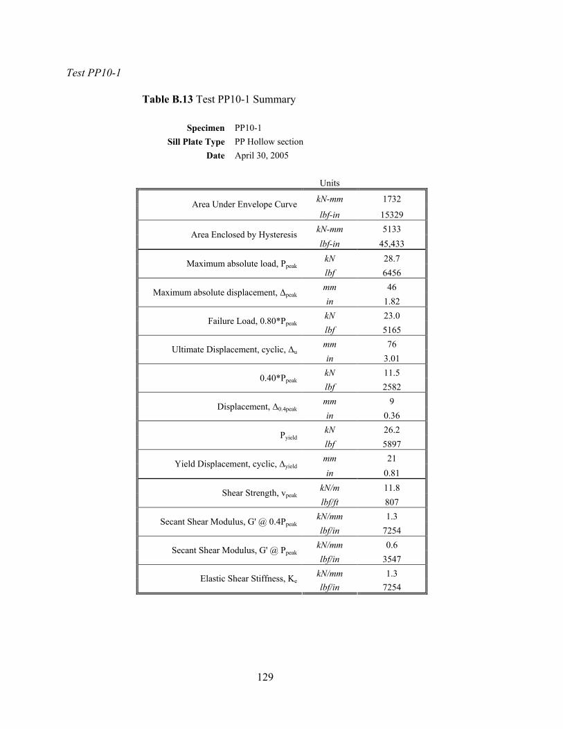
129
Test PP10-1
Table B.13 Test PP10-1 Summary
Specimen PP10-1 Sill Plate Type PP Hollow section
Date April 30, 2005 Units
kN-mm 1732 Area Under Envelope Curve lbf-in 15329
kN-mm 5133 Area Enclosed by Hysteresis lbf-in 45,433
kN 28.7 Maximum absolute load, Ppeak lbf 6456 mm 46 Maximum absolute displacement, ∆peak in 1.82 kN 23.0 Failure Load, 0.80*Ppeak lbf 5165 mm 76 Ultimate Displacement, cyclic, ∆u in 3.01 kN 11.5 0.40*Ppeak lbf 2582 mm 9 Displacement, ∆0.4peak in 0.36 kN 26.2 Pyield lbf 5897 mm 21 Yield Displacement, cyclic, ∆yield in 0.81
kN/m 11.8 Shear Strength, vpeak lbf/ft 807
kN/mm 1.3 Secant Shear Modulus, G' @ 0.4Ppeak lbf/in 7254
kN/mm 0.6 Secant Shear Modulus, G' @ Ppeak lbf/in 3547
kN/mm 1.3 Elastic Shear Stiffness, Ke lbf/in 7254
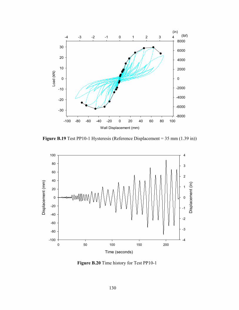
130
Wall Displacement (mm)
-100 -80 -60 -40 -20 0 20 40 60 80 100
Load
(kN
)
-30
-20
-10
0
10
20
30
(in)-4 -3 -2 -1 0 1 2 3 4 (lbf)
-8000
-6000
-4000
-2000
0
2000
4000
6000
8000
Figure B.19 Test PP10-1 Hysteresis (Reference Displacement = 35 mm (1.39 in))
Time (seconds)
0 50 100 150 200
Dis
plac
emen
t (m
m)
-100
-80
-60
-40
-20
0
20
40
60
80
100
Dis
plac
emen
t (in
)
-4
-3
-2
-1
0
1
2
3
4
Figure B.20 Time history for Test PP10-1

131
Table B.14 Test PP10-1 Energy and damping data
Hysteretic Energy
Strain Energy
WD U EVDR, ζeq
Positive Negative Positive Negative (kN-mm) (kN-mm) (radians)Initiation 1 1.01 -1.31 0.03 -0.33 0.07 0.01 0.44
2 1.07 -1.31 0.05 -0.33 0.02 0.03 0.073 1.05 -1.28 0.05 -0.33 0.07 0.03 0.214 1.09 -1.30 0.05 -0.33 0.10 0.03 0.285 1.09 -1.31 0.05 -0.33 0.08 0.03 0.246 1.11 -1.45 0.08 -0.38 0.08 0.04 0.15
Primary 7 2.47 -2.32 0.71 -0.74 0.68 0.88 0.068 1.18 -1.61 0.13 -0.46 0.05 0.08 0.059 1.39 -1.55 0.20 -0.43 0.06 0.14 0.04
10 1.39 -1.55 0.20 -0.43 -0.08 0.14 -0.0411 1.40 -1.57 0.20 -0.43 0.04 0.14 0.0212 1.41 -1.55 0.23 -0.41 0.10 0.16 0.0513 1.40 -1.57 0.23 -0.43 0.07 0.16 0.04
Primary 14 3.62 -3.78 1.50 -1.65 3.00 2.71 0.0915 2.14 -2.35 0.56 -0.86 0.69 0.60 0.0916 2.34 -2.34 0.69 -0.84 0.49 0.80 0.0517 2.35 -2.36 0.69 -0.86 0.46 0.81 0.0518 2.33 -2.36 0.69 -0.86 0.39 0.80 0.0419 2.30 -2.36 0.69 -0.86 0.55 0.79 0.0620 2.32 -2.36 0.69 -0.86 0.31 0.79 0.03
Primary 21 6.40 -8.57 4.75 -5.28 20.07 15.20 0.1122 6.99 -6.07 5.33 -3.81 15.86 18.64 0.0723 4.72 -5.63 3.38 -3.51 8.83 7.98 0.0924 4.72 -5.62 3.43 -3.48 10.32 8.09 0.10
Primary 25 8.39 -10.33 6.91 -6.99 16.18 28.99 0.0426 8.41 -10.06 7.04 -6.96 19.95 29.60 0.0527 8.32 -8.43 7.09 -6.07 18.88 29.50 0.0528 7.23 -8.44 6.35 -6.07 21.30 22.97 0.0729 7.23 -8.42 6.35 -6.07 19.97 22.96 0.0730 7.20 6.35 10.27 22.87 0.04
Primary 31 14.29 -12.99 11.35 -10.64 71.34 81.12 0.0732 10.55 -8.41 9.04 -8.13 38.54 47.70 0.0633 10.36 -8.44 8.94 -8.13 35.58 46.32 0.06
Primary 34 19.02 -21.70 17.86 -19.69 253.66 169.82 0.1235 13.58 -13.85 15.32 -15.37 106.06 103.97 0.0836 13.78 -13.99 15.34 -15.44 94.36 105.68 0.07
Primary 37 24.59 -26.70 29.26 -28.93 496.46 359.74 0.1138 15.37 -15.66 23.06 -22.33 184.79 177.25 0.0839 15.29 -15.70 23.09 -22.45 163.42 176.50 0.07
Primary 40 28.90 -28.54 46.05 -46.38 1022.14 665.50 0.1241 15.61 -15.73 36.40 -35.38 310.25 284.10 0.0942 15.48 -15.89 36.53 -35.43 270.04 282.74 0.08
Primary 43 29.74 -25.45 63.80 -63.80 1273.65 948.62 0.1144 13.70 -12.33 51.03 -49.35 350.75 349.56 0.0845 13.36 -12.38 50.83 -49.40 293.37 339.57 0.07
Total Estimated Energy 5133 kN-mm
Cycle Maximums
Cycle Number
Load (kN) Deflection (mm)
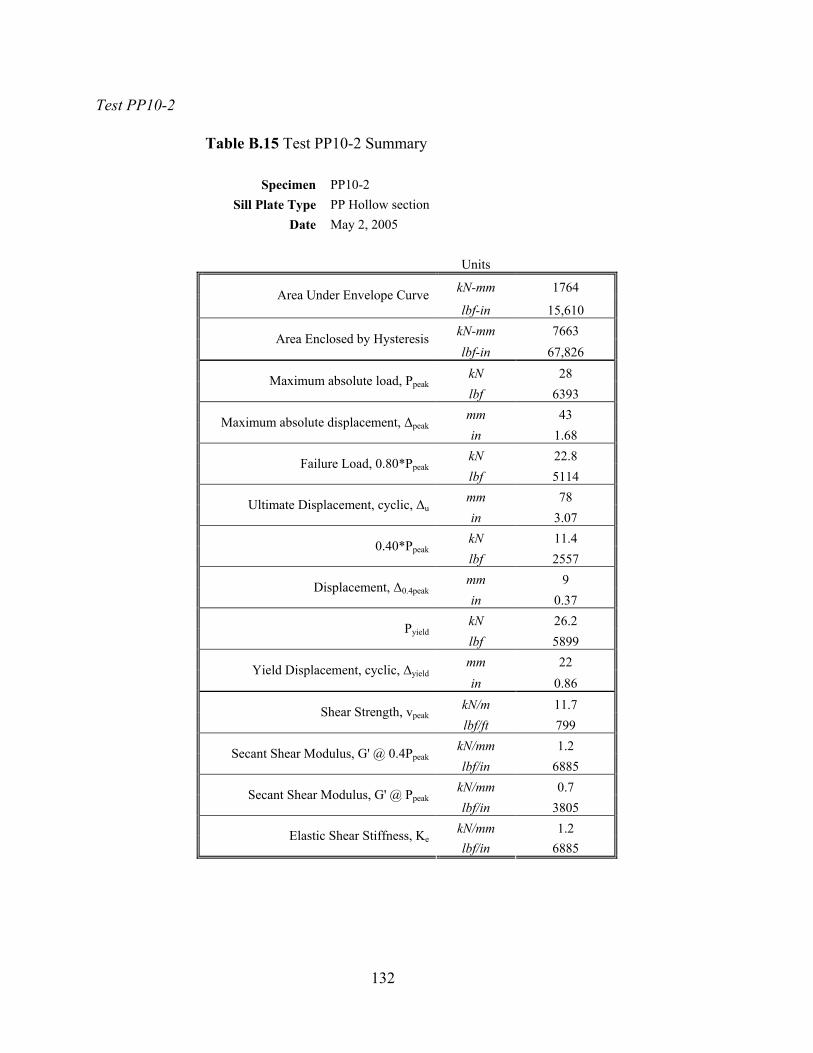
132
Test PP10-2
Table B.15 Test PP10-2 Summary
Specimen PP10-2 Sill Plate Type PP Hollow section
Date May 2, 2005 Units
kN-mm 1764 Area Under Envelope Curve lbf-in 15,610
kN-mm 7663 Area Enclosed by Hysteresis lbf-in 67,826
kN 28 Maximum absolute load, Ppeak lbf 6393 mm 43 Maximum absolute displacement, ∆peak in 1.68 kN 22.8 Failure Load, 0.80*Ppeak lbf 5114 mm 78 Ultimate Displacement, cyclic, ∆u in 3.07 kN 11.4 0.40*Ppeak lbf 2557 mm 9 Displacement, ∆0.4peak in 0.37 kN 26.2 Pyield lbf 5899 mm 22 Yield Displacement, cyclic, ∆yield in 0.86
kN/m 11.7 Shear Strength, vpeak lbf/ft 799
kN/mm 1.2 Secant Shear Modulus, G' @ 0.4Ppeak lbf/in 6885
kN/mm 0.7 Secant Shear Modulus, G' @ Ppeak lbf/in 3805
kN/mm 1.2 Elastic Shear Stiffness, Ke lbf/in 6885
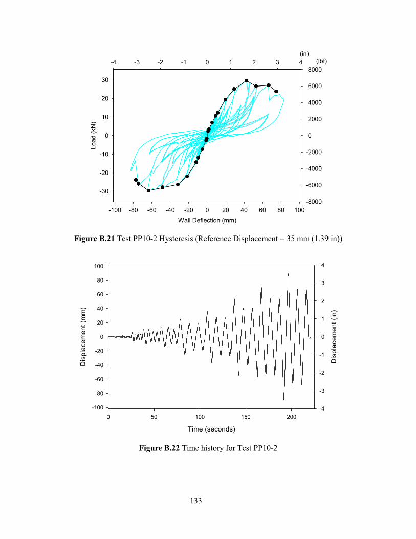
133
Wall Deflection (mm)-100 -80 -60 -40 -20 0 20 40 60 80 100
Load
(kN
)
-30
-20
-10
0
10
20
30
(in)-4 -3 -2 -1 0 1 2 3 4 (lbf)
-8000
-6000
-4000
-2000
0
2000
4000
6000
8000
Figure B.21 Test PP10-2 Hysteresis (Reference Displacement = 35 mm (1.39 in))
Time (seconds)
0 50 100 150 200
Dis
plac
emen
t (m
m)
-100
-80
-60
-40
-20
0
20
40
60
80
100
Dis
plac
emen
t (in
)
-4
-3
-2
-1
0
1
2
3
4
Figure B.22 Time history for Test PP10-2
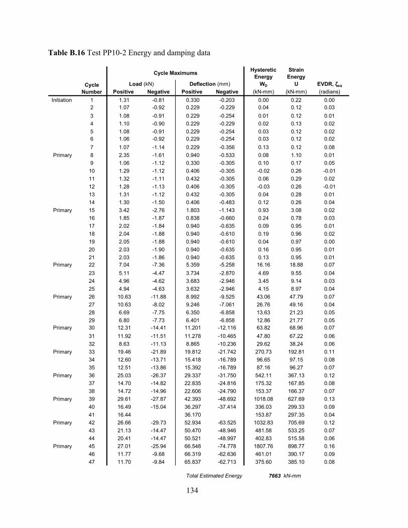
134
Table B.16 Test PP10-2 Energy and damping data
Hysteretic Energy
Strain Energy
WD U EVDR, ζeq
Positive Negative Positive Negative (kN-mm) (kN-mm) (radians)Initiation 1 1.31 -0.81 0.330 -0.203 0.00 0.22 0.00
2 1.07 -0.92 0.229 -0.229 0.04 0.12 0.033 1.08 -0.91 0.229 -0.254 0.01 0.12 0.014 1.10 -0.90 0.229 -0.229 0.02 0.13 0.025 1.08 -0.91 0.229 -0.254 0.03 0.12 0.026 1.06 -0.92 0.229 -0.254 0.03 0.12 0.027 1.07 -1.14 0.229 -0.356 0.13 0.12 0.08
Primary 8 2.35 -1.61 0.940 -0.533 0.08 1.10 0.019 1.06 -1.12 0.330 -0.305 0.10 0.17 0.05
10 1.29 -1.12 0.406 -0.305 -0.02 0.26 -0.0111 1.32 -1.11 0.432 -0.305 0.06 0.29 0.0212 1.28 -1.13 0.406 -0.305 -0.03 0.26 -0.0113 1.31 -1.12 0.432 -0.305 0.04 0.28 0.0114 1.30 -1.50 0.406 -0.483 0.12 0.26 0.04
Primary 15 3.42 -2.76 1.803 -1.143 0.93 3.08 0.0216 1.85 -1.87 0.838 -0.660 0.24 0.78 0.0317 2.02 -1.84 0.940 -0.635 0.09 0.95 0.0118 2.04 -1.88 0.940 -0.610 0.19 0.96 0.0219 2.05 -1.88 0.940 -0.610 0.04 0.97 0.0020 2.03 -1.90 0.940 -0.635 0.16 0.95 0.0121 2.03 -1.86 0.940 -0.635 0.13 0.95 0.01
Primary 22 7.04 -7.36 5.359 -5.258 16.16 18.88 0.0723 5.11 -4.47 3.734 -2.870 4.69 9.55 0.0424 4.96 -4.62 3.683 -2.946 3.45 9.14 0.0325 4.94 -4.63 3.632 -2.946 4.15 8.97 0.04
Primary 26 10.63 -11.88 8.992 -9.525 43.06 47.79 0.0727 10.63 -8.02 9.246 -7.061 26.76 49.16 0.0428 6.69 -7.75 6.350 -6.858 13.63 21.23 0.0529 6.80 -7.73 6.401 -6.858 12.86 21.77 0.05
Primary 30 12.31 -14.41 11.201 -12.116 63.82 68.96 0.0731 11.92 -11.51 11.278 -10.465 47.80 67.22 0.0632 8.63 -11.13 8.865 -10.236 29.62 38.24 0.06
Primary 33 19.46 -21.89 19.812 -21.742 270.73 192.81 0.1134 12.60 -13.71 15.418 -16.789 96.65 97.15 0.0835 12.51 -13.86 15.392 -16.789 87.16 96.27 0.07
Primary 36 25.03 -26.37 29.337 -31.750 542.11 367.13 0.1237 14.70 -14.82 22.835 -24.816 175.32 167.85 0.0838 14.72 -14.96 22.606 -24.790 153.37 166.37 0.07
Primary 39 29.61 -27.87 42.393 -48.692 1018.08 627.69 0.1340 16.49 -15.04 36.297 -37.414 336.03 299.33 0.0941 16.44 36.170 153.87 297.35 0.04
Primary 42 26.66 -29.73 52.934 -63.525 1032.83 705.69 0.1243 21.13 -14.47 50.470 -48.946 481.58 533.25 0.0744 20.41 -14.47 50.521 -48.997 402.83 515.58 0.06
Primary 45 27.01 -25.94 66.548 -74.778 1807.76 898.77 0.1646 11.77 -9.68 66.319 -62.636 461.01 390.17 0.0947 11.70 -9.84 65.837 -62.713 375.60 385.10 0.08
Total Estimated Energy 7663 kN-mm
Cycle Maximums
Cycle Number
Load (kN) Deflection (mm)
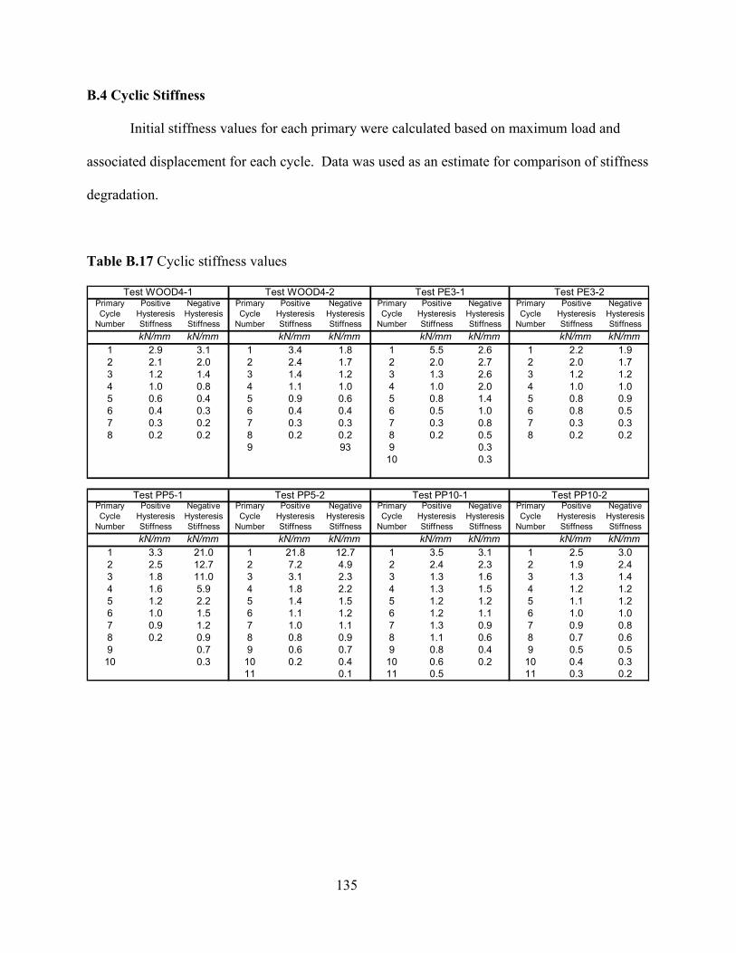
135
B.4 Cyclic Stiffness
Initial stiffness values for each primary were calculated based on maximum load and
associated displacement for each cycle. Data was used as an estimate for comparison of stiffness
degradation.
Table B.17 Cyclic stiffness values
Primary Cycle
Number
Positive Hysteresis Stiffness
Negative Hysteresis Stiffness
Primary Cycle
Number
Positive Hysteresis Stiffness
Negative Hysteresis Stiffness
Primary Cycle
Number
Positive Hysteresis Stiffness
Negative Hysteresis Stiffness
Primary Cycle
Number
Positive Hysteresis Stiffness
Negative Hysteresis Stiffness
kN/mm kN/mm kN/mm kN/mm kN/mm kN/mm kN/mm kN/mm1 2.9 3.1 1 3.4 1.8 1 5.5 2.6 1 2.2 1.92 2.1 2.0 2 2.4 1.7 2 2.0 2.7 2 2.0 1.73 1.2 1.4 3 1.4 1.2 3 1.3 2.6 3 1.2 1.24 1.0 0.8 4 1.1 1.0 4 1.0 2.0 4 1.0 1.05 0.6 0.4 5 0.9 0.6 5 0.8 1.4 5 0.8 0.96 0.4 0.3 6 0.4 0.4 6 0.5 1.0 6 0.8 0.57 0.3 0.2 7 0.3 0.3 7 0.3 0.8 7 0.3 0.38 0.2 0.2 8 0.2 0.2 8 0.2 0.5 8 0.2 0.2
9 93 9 0.310 0.3
Primary Cycle
Number
Positive Hysteresis Stiffness
Negative Hysteresis Stiffness
Primary Cycle
Number
Positive Hysteresis Stiffness
Negative Hysteresis Stiffness
Primary Cycle
Number
Positive Hysteresis Stiffness
Negative Hysteresis Stiffness
Primary Cycle
Number
Positive Hysteresis Stiffness
Negative Hysteresis Stiffness
kN/mm kN/mm kN/mm kN/mm kN/mm kN/mm kN/mm kN/mm1 3.3 21.0 1 21.8 12.7 1 3.5 3.1 1 2.5 3.02 2.5 12.7 2 7.2 4.9 2 2.4 2.3 2 1.9 2.43 1.8 11.0 3 3.1 2.3 3 1.3 1.6 3 1.3 1.44 1.6 5.9 4 1.8 2.2 4 1.3 1.5 4 1.2 1.25 1.2 2.2 5 1.4 1.5 5 1.2 1.2 5 1.1 1.26 1.0 1.5 6 1.1 1.2 6 1.2 1.1 6 1.0 1.07 0.9 1.2 7 1.0 1.1 7 1.3 0.9 7 0.9 0.88 0.2 0.9 8 0.8 0.9 8 1.1 0.6 8 0.7 0.69 0.7 9 0.6 0.7 9 0.8 0.4 9 0.5 0.510 0.3 10 0.2 0.4 10 0.6 0.2 10 0.4 0.3
11 0.1 11 0.5 11 0.3 0.2
Test PP5-1 Test PP5-2 Test PP10-1 Test PP10-2
Test WOOD4-1 Test WOOD4-2 Test PE3-1 Test PE3-2
136
B.5 Load Washer
Load washer data has been included to document load distribution throughout the length
of sills, throughout testing. Both monotonic and cyclic results are included here. Figures B.25-
B.28 plot monotonic time histories for load washers, whereas Figures B.29-B.31 plot the
displacement-load history to compare how individual washers gain load as load is applied.
Cyclic results plot time histories for load washers for each test. The applied load is
plotted behind all three load washer data plots for comparison. Initial load offset for load
washers exists from tightening bolts prior to testing. The “loss” of this prestress and the
resulting shift in the offset for individual washers exists as sill fibers compress and material
splits, causing the force on bolts to reduce.
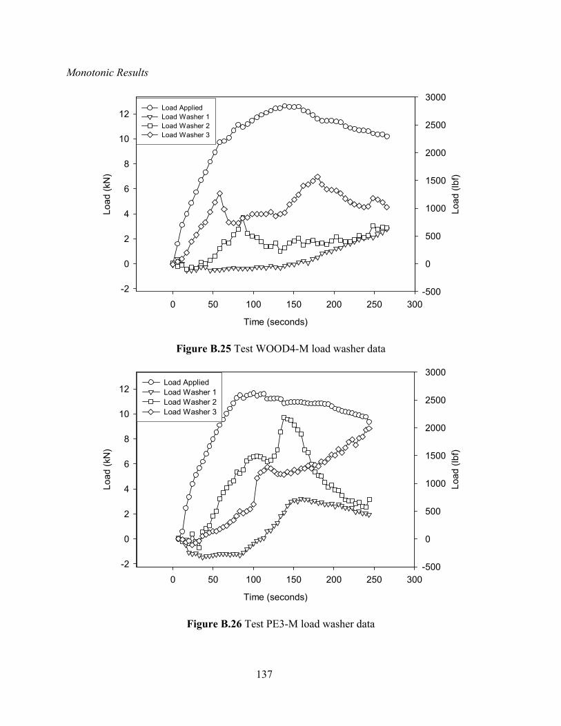
137
Monotonic Results
Time (seconds)
0 50 100 150 200 250 300
Load
(kN
)
-2
0
2
4
6
8
10
12Load AppliedLoad Washer 1Load Washer 2Load Washer 3
Load
(lbf
)
-500
0
500
1000
1500
2000
2500
3000Load AppliedLoad Washer 1Load Washer 2Load Washer 3
Figure B.25 Test WOOD4-M load washer data
Time (seconds)
0 50 100 150 200 250 300
Load
(kN
)
-2
0
2
4
6
8
10
12Load AppliedLoad Washer 1Load Washer 2Load Washer 3
Load
(lbf
)
-500
0
500
1000
1500
2000
2500
3000Load AppliedLoad Washer 1Load Washer 2Load Washer 3
Figure B.26 Test PE3-M load washer data
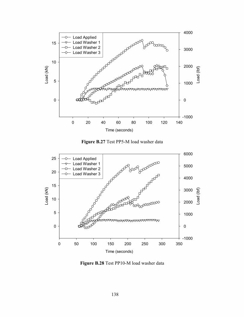
138
Time (seconds)
0 20 40 60 80 100 120 140
Load
(kN
)
0
5
10
15Load AppliedLoad Washer 1Load Washer 2Load Washer 3
Load
(lbf
)
-1000
0
1000
2000
3000
4000Load AppliedLoad Washer 1Load Washer 2Load Washer 3
Figure B.27 Test PP5-M load washer data
Time (seconds)
0 50 100 150 200 250 300 350
Load
(kN
)
0
5
10
15
20
25 Load AppliedLoad Washer 1Load Washer 2Load Washer 3
Load
(lbf
)
-1000
0
1000
2000
3000
4000
5000
6000Load AppliedLoad Washer 1Load Washer 2Load Washer 3
Figure B.28 Test PP10-M load washer data
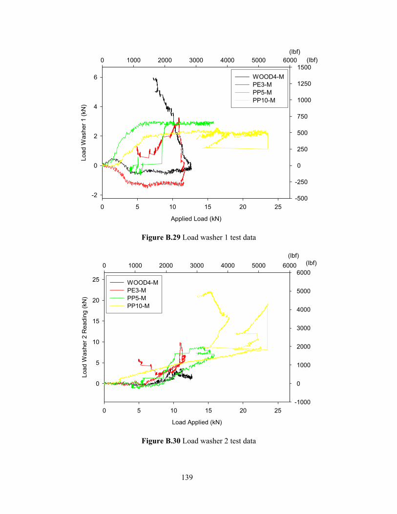
139
Applied Load (kN)
0 5 10 15 20 25
Load
Was
her 1
(kN
)
-2
0
2
4
6 1-M2-M3-M4-M
(lbf)0 1000 2000 3000 4000 5000 6000 (lbf)
-500
-250
0
250
500
750
1000
1250
1500WOOD4-MPE3-MPP5-MPP10-M
Figure B.29 Load washer 1 test data
Load Applied (kN)
0 5 10 15 20 25
Load
Was
her 2
Rea
ding
(kN
)
0
5
10
15
20
25 1-M2-M3-M4-M
(lbf)0 1000 2000 3000 4000 5000 6000 (lbf)
-1000
0
1000
2000
3000
4000
5000
6000WOOD4-MPE3-MPP5-MPP10-M
Figure B.30 Load washer 2 test data
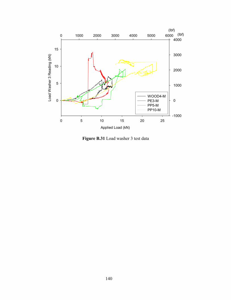
140
Applied Load (kN)
0 5 10 15 20 25
Load
Was
her 3
Rea
ding
(kN
)
0
5
10
15
1-M2-M3-M4-M
(lbf)0 1000 2000 3000 4000 5000 6000 (lbf)
-1000
0
1000
2000
3000
4000
WOOD4-MPE3-MPP5-MPP10-M
Figure B.31 Load washer 3 test data
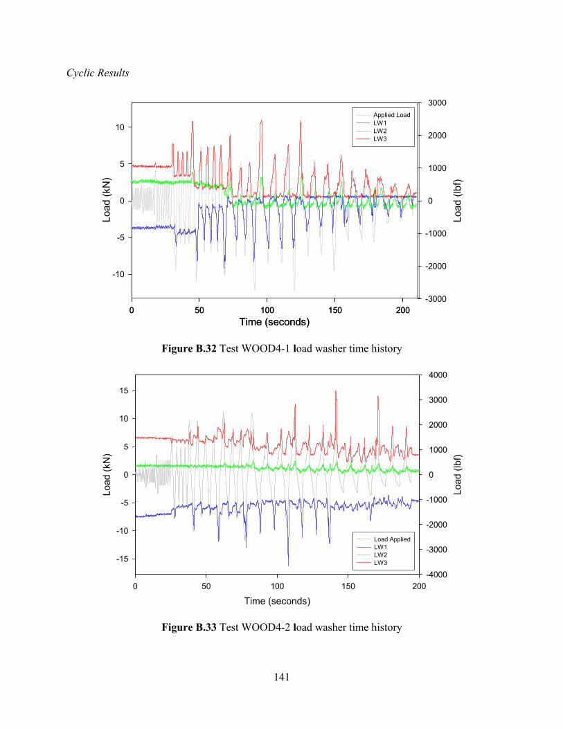
141
Cyclic Results
Time (seconds)0 50 100 150 200
Load
(kN
)
-10
-5
0
5
10
Time (seconds)0 50 100 150 200
Load
(lbf
)
-3000
-2000
-1000
0
1000
2000
3000Applied LoadLW1LW2LW3
Figure B.32 Test WOOD4-1 load washer time history
Time (seconds)0 50 100 150 200
Load
(kN
)
-15
-10
-5
0
5
10
15
Load AppliedLW 1LW 2LW 3
Load
(lbf
)
-4000
-3000
-2000
-1000
0
1000
2000
3000
4000
Load AppliedLW1LW2LW3
Figure B.33 Test WOOD4-2 load washer time history
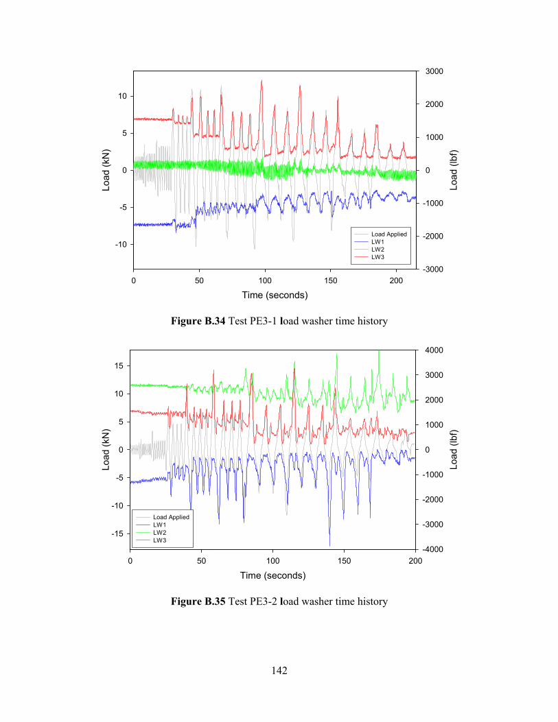
142
Time (seconds)0 50 100 150 200
Load
(kN
)
-10
-5
0
5
10
Load AppliedLoad Washer 1Load Washer 2Load Washer 3
Load
(lbf
)
-3000
-2000
-1000
0
1000
2000
3000
Load AppliedLW1LW2LW3
Figure B.34 Test PE3-1 load washer time history
Time (seconds)0 50 100 150 200
Load
(kN
)
-15
-10
-5
0
5
10
15
Load AppliedLoad Washer 1Load Washer 2Load Washer 3
Load
(lbf
)
-4000
-3000
-2000
-1000
0
1000
2000
3000
4000
Load AppliedLW1LW2LW3
Figure B.35 Test PE3-2 load washer time history
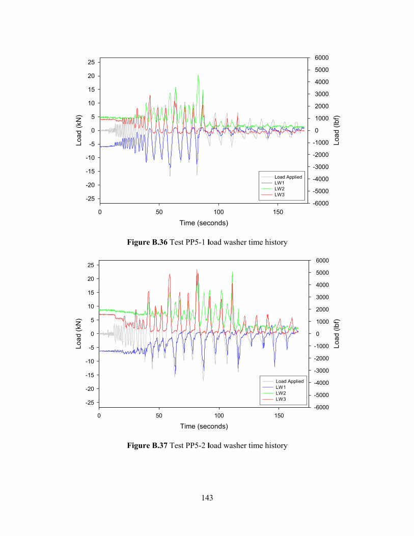
143
Time (seconds)0 50 100 150
Load
(kN
)
-25
-20
-15
-10
-5
0
5
10
15
20
25
Load AppliedLW1LW2LW3
Load
(lbf
)
-6000
-5000
-4000
-3000
-2000
-1000
0
1000
2000
3000
4000
5000
6000
Load AppliedLW1LW2LW3
Figure B.36 Test PP5-1 load washer time history
Time (seconds)0 50 100 150
Load
(kN
)
-25
-20
-15
-10
-5
0
5
10
15
20
25 Load AppliedLoad Washer 1Load Washer 2Load Washer 3
Load
(lbf
)
-6000
-5000
-4000
-3000
-2000
-1000
0
1000
2000
3000
4000
5000
6000
Load AppliedLW1LW2LW3
Figure B.37 Test PP5-2 load washer time history
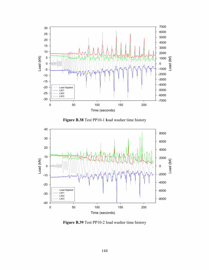
144
Time (seconds)0 50 100 150 200
Load
(kN
)
-30
-25
-20
-15
-10
-5
0
5
10
15
20
25
30
Load AppliedLoad Washer 1Load Washer 2Load Washer 3
Load
(lbf
)
-7000
-6000
-5000
-4000
-3000
-2000
-1000
0
1000
2000
3000
4000
5000
6000
7000
Load AppliedLW1LW2LW3
Figure B.38 Test PP10-1 load washer time history
Time (seconds)0 50 100 150 200
Load
(kN
)
-40
-30
-20
-10
0
10
20
30
40
Load AppliedLoad Washer 1Load Washer 2Load Washer 3
Load
(lbf
)
-8000
-6000
-4000
-2000
0
2000
4000
6000
8000
Load AppliedLW1LW2LW3
Figure B.39 Test PP10-2 load washer time history