solar collector installation manual -...
TRANSCRIPT

Rev. 2013,04,23
Module 4
Solar Collector
Installation Manual1, 2, 3 & 4 Collector Pre-Heat Appliances
(EWRA1, EWRA2)
1 & 2 Collector Single Tank Appliances (USA only)
( )EWRA1-ST, EWRA2-ST
Solar Water Heating AppliancesEnerWorks Inc.
969 Juliana Drive
Woodstock, ON
N4V 1C1, Canada
Tel: (519) 268-6500
Toll-free: 1-877-268-6502
Fax: (519) 268-6292
www.enerworks.com
© 2013 enerworks

Solar CollectorInstallation Manual
EnerWorks encourages installers of EnerWorks products to always keep workmanship, best practices and safety in mind. An organized installation will benefit both installer and end-user.
The EnerWorks Solar Collector is one of the highest-rated in North America. This assessment was carried out by third-party testing under the supervision and scrutiny of the Solar Rating & Certification Corporation™ (SRCC™). The EnerWorks Heat Safe Solar Collector has SRCC™ OG-100 certification (Certification #: 100-2005-014A) and the EnerWorks Residential Solar Water Heating Appliances are certified to OG-300 standards. This certification does not imply endorsement or warranty of these products by the SRCC™.
The Pre-Heat and Single Tank Appliances described in this manual, when properly installed and maintained, meet or exceed the standards established by the Florida Solar Energy Center (FSEC), in accordance with Section 377.705, Florida Statutes. This certification does not imply endorsement or warranty of this product by the Florida Solar Energy Center or the State of Florida.
The EnerWorks Pre-Heat Appliance is the first system in North America to achieve the Canadian Standards Association (CSA) certification (CSA F379.1). This certification does not imply endorsement or warranty by CSA.
Foreword
Recognize this symbol as an indication of important safety information!
EnerWorks Residential Solar Water Heating Appliances must be installed as
directed by this manual by an EnerWorks-authorized dealer or warranty is void.
CALIFORNIA PROPOSITION 65 WARNING: This product contains chemicals known to the State of California to cause cancer, birth defects or other reproductive harm.
Appliance must only be installed by an EnerWorks-authorized
dealer or warranty is void.

Solar CollectorInstallation Manual
CARE, HANDLING & STORAGE
EnerWorks Solar Collectors are manufactured with tempered glass. Though extremely resistant to impact, tempered glass can break if an edge is subjected to stress. During storage and installation, protect glass edges. Glass breakage is not covered by warranty.
Store collectors in a dry place, lying flat with glass up, or leaning on long edge with glass facing out and connections at top. Protect collector from scratches and damage by placing it on a soft surface such as a blanket or cardboard. When hoisting collectors to roof, be very careful not to bang glass edge. Collectors must not be levered over ladder or eave as they may be damaged. Be very careful of collector connections as they are soft copper and may be easily damaged. A leak-proof heat-transfer fluid loop can only be achieved if collector connections are not damaged.
Do not store collectors outside with glass face down. Due to EnerWorks’ patented stagnation-control device, back of collector is not sealed to atmosphere. Rain may enter collector if it is stored face down. Any damage due to ingress of water is not covered by warranty.
It is best to store both the EnerWorks Solar Collectors and the EnerWorks Energy Station in a cool, dry place.
1Module 4

Contents
1 – Safety2 – EnerWorks Solar Water Heating Appliance
3 – Site Evaluation
4 – Line-Set Installation
5 – C-Channel Installation
6 – Solar Collector Installation
7 – Collector Flashing and Leaf-Guard Installation
2.1 Description2.2 Pre-heat Appliance Schematic2.3 Single Tank Appliance Schematic (USA only)
3.1 Collector Location, Orientation and Shading
tanding Seam M
3.2 Available Roof Space3.3 Collector Racks 3.4 Line-Set3.5 Location of Energy Station and Solar Storage Tank
4.1 Line-Set Description4.2 Line-Set Routing4.3 Line-Set Installation
5.1 Locating Rafters and Positioning C-Channel5.2 Securing C-channel Asphalt roof (Shingles)5.3 Securing C-channel to S etal Roof5.4 Roof-Penetration Flashing Boot
6.1 Preparation of Collector(s)
6.2 Hoisting and Securing Collectors to Roof
6.3 Securing Collectors to C-Channel6.4 Collector Configurations
6.5 Line-Set and Control-Wire Connections
6.1.1 Converting Collector(s) from Left to Right6.1.2 Installing Temperature Sensor (Thermistor)6.1.3 Installing Collector Mounting Brackets
6.2.1 Ladder Hoist or Shingle-Lift 6.2.2 Scissor Lift or Articulating or Forklift Boom 6.2.3 Scaffolding6.2.4 Ladder and Lift Line
6.4.1 One-Collector Configuration6.4.2 Two-Collector Configuration6.4.3 Three-Collector Configuration6.4.4 Four-Collector Configuration
7.1 Side-Flashing for 1-Collector Appliances7.2 Center-Flashing for 2, 3 and 4-Collector Appliances7.3 Leaf-Guard Installation
Product and Installation Registration FormResidential Site SurveyTool & Supply Checklist
.................................................................................................................................... 3............................................................................... 4
.......................................................................................................................7
........................................................... 8 ............................................................................................................... 8
......................................................................................................... 11
..................................................................................................... 16
..................................................................... 31
..................................................................................................................4........................................................................5
...............................................................6
................................................................... 7 .................................................................................................... 8
............................................................................................................ 8 ...................................................................................................................... 8
..................................................................................................... 8 ........................................................................................................... 9
....................................................................................................10
................................................................. 11 ................................................................. 13
........................................................ 15 ................................................................................... 15
.......................................................................................... 16
...................................................................................... 23
.................................................................................... 26 ................................................................................... 27
................................................................... 17 ............................................................... 20
...................................................................... 21 ...................................................................... 22
................................................................... 23 ............................................................................................................. 23
.................................................................................................. 24 ................................................................................ 25
................................................................................... 26
................................................................................... 27 .................................................................................... 28
......................................................................... 29 ......................................................................... 30
...................................................... 31 ................................................................................................ 33
..................................................................................... 34................................................................................................................. 35.................................................................................................................. 36
2 Module 4
Solar CollectorInstallation Manual

1 – Safety
EnerWorks assumes no responsibility for damage, loss or injury related to installation of this appliance.
Observe any and all regulations relating to installation of solar appliances and to plumbing to potable water supply. Plumbing and/or building permits may be necessary. EnerWorks Solar Water Heating Appliances utilize a single-wall as well as double-wall heat exchangers. Selection must be acceptable in the jurisdictions.
Assemblies, installation and materials used during installation shall meet applicable requirements of local, regional, state, provincial, and federal regulations and fire codes, national roofing contractors association practices. Any penetrations made in drywall or any other firewall must be fixed to maintain integrity of fire protection.
All persons working on roofs should have successfully completed a fall-safety course and should be properly equipped with appropriate safety equipment.
3Module 4
Solar CollectorInstallation Manual

2 – EnerWorks Solar Water Heating Appliance
The EnerWorks Solar Water Heating Appliance has four main parts – the solar collectors, the line-set, the Energy Station and the solar storage tank.
The Energy Station uses a pump to circulate a heat-transfer fluid through the “collector loop”. This collector loop includes the solar collectors, the fluid lines or “line-set” and a heat exchanger. The collector loop is a “closed loop”, meaning there is no contact of the heat transfer fluid with your potable water or with the atmosphere. The collector loop contains only a small volume of heat-transfer fluid which is freeze-protected. Though freeze protection may not be necessary in all areas, the heat-transfer fluid also has an elevated boiling point and so is suitable throughout North America.
When exposed to sunlight, the solar collectors get hot. Passive overheat-protection prevents temperature exceeding 275°F (135°C); pressure and flow conditions depends on the system. As the heat-transfer fluid passes through the collectors, it absorbs heat and then travels down the line-set to the Energy Station. The hot fluid passes through the heat exchanger and heat is transferred to the potable water. After giving up its heat to the potable water, the cool heat-transfer fluid is pumped back to the solar collectors to be heated again. Hot potable water is stored in the solar storage tank.
In the Pre-Heat Solar Water Heating Appliance (Fig. 2.2), the solar storage tank is a standard, North American, electric hot-water tank. No power is connected to this tank – it only stores solar-heated water. The solar storage tank is plumbed in series with the original water-heater (electric, fossil fuel, or on-demand). Whenever hot water is used in the home, solar heated water leaves the solar storage tank and enters the original water-heater. The original water-heater now requires much less energy for water heating.
Thus, the Appliance displaces energy, but it does not replace the original water-heater. The original heater guarantees hot water even under poor solar conditions (at night or when very cloudy). It also ensures that hot water is stored or supplied at an appropriate temperature to kill harmful bacteria. The acceptable temperature set-point is specified in local plumbing codes. Do not turn off or bypass the back-up water-heater. Even in summer months, additional heat from the back-up heater may be required.
The Single Tank Solar Water Heating Appliance (Fig. 2.3) incorporates solar water-heating and auxiliary water-heating in a single tank. The Single Tank Appliance is the solar solution for homes (in the United States) that cannot accommodate two tanks. For more information on Appliance components and function, please see the Owner Manual.
2.1 Description
Solar CollectorInstallation Manual
4 Module 4

5Module 4
2.2 Pre-Heat Appliance Schematic
Fig. 2.2 EnerWorks Pre-Heat Solar Water Heating Appliance (with optional leaf-guard)
Solar CollectorInstallation Manual
10
12 11
9
1 2
3 4 5
6
8
7
13
15
9 14
14
16
18 17
Solar collectors (1 to 4)
Line-set roof-penetration (behind flashing)
Heat transfer fluid line from collectors to
Energy Station (red – carries hot fluid)
Heat transfer fluid line from Energy Station to
collectors (blue – carries cool fluid)
Cold mains water supply (blue)
Hot water supply to home (red)
Thermosiphon loop,
solar-heated water to storage tank (red)
Thermometer
Bypass valves (to isolate Appliance for service)
Anti-scald valve (not included, may be required by code)
1
2
3
4
5
6
7
8
12
15
16
17
18
13
9
10
11
14 Heat trap (U-bend limits heat loss)
Solar storage tank
Energy Station
Pre-existing or auxiliary hot water tank or on-demand heater
Pressure relief valve (inside cover)
Thermosiphon loop feed (from storage)

2.3 Single Tank Appliance Schematic (USA only)
Fig. 2.3 EnerWorks Single Tank Solar Water Heating Appliance (with optional leaf-guard)
Solar CollectorInstallation Manual
6
1 2
3 4
7 5
9
14
13 12
10
11
8
Solar collectors (1 or 2)
Line-set roof-penetration (behind flashing)
Heat transfer fluid line from collectors to
Energy Station (red – carries hot fluid)
Heat transfer fluid line from Energy Station
to collectors (blue – carries cool fluid)
Hot water supply to home (red)
Anti-scald valve (required)
Cold mains water supply (blue)
Solar storage tank with electric back-up
Thermometer
Thermosiphon loop, solar-heated water to storage tank (red)
1
2
3
4
5
6
7
8
12
13
9
10
11
14
Energy Station
Pressure relief valve (inside cover)
Thermosiphon loop feed (from storage)
Heat trap (U-bend limits heat loss)
6 Module 4

3 - Site Evaluation
To achieve good performance and a good return on investment, the Appliance must be sized correctly and it must be oriented properly. Site evaluation is necessary to determine whether a site is appropriate and to evaluate the complexity of the installation. It is also necessary to determine the hot water loads, number of individuals in a home, number of collectors and size of solar storage tank.
A site survey (see Appendix – Residential Site Survey) has been developed to assist installers in evaluating potential installation locations. This can be removed from the Appendices and copied as needed. Solar simulation software may assist in determining the best location and orientation for the solar collectors.
For roof-mounting, installer should ensure that roof cladding or sheathing is in good repair. Also ensure that rafters and trusses are adequate to support weight of solar collector(s) and mounting assembly.
Building and plumbing permits and/or inspections may be necessary to proceed with installation. Follow all code requirements and regulations.
Collector(s) should face as close to south as possible for optimal performance. Within 45° of south is acceptable as there is less than 10% loss (Fig. 3.1.1).
The roof angle from horizontal for optimal year-round performance is equivalent to latitude of location plus or minus 15°. A steeper angle provides better winter performance as the sun is lower in the sky. Collectors will also shed snow more effectively. A shallow angle maximizes energy capture in summer when sun is high. Be cautious of placement on low angle roofs due to snow shedding and potential for ice-damming. A minimum collector angle of 14° (3:12 pitch) is necessary for stagnation-control device to function.
Shading of collectors greatly reduces performance. When selecting installation location, consider potential shading by trees and other buildings, especially between peak solar hours of 10:00 and 15:00. A Solar Pathfinder or similar device may be used to determine potential shading throughout the year.
3.1 Collector Location, Orientation and Shading
Fig. 3.1.1 – Collector Orientation.
7Module 4
Solar CollectorInstallation Manual

3.2 Available Roof Space
3.3 Collector Racks
3.4 Line-Set
3.5 Location of Energy Station and Solar Storage Tank
4.1 Line-set Description
Appliance may consist of one to four collectors depending on required volume of hot water. Check appliance specification sheet for sizing guidelines. Each collector is 4’ x 8’ (1.219 m x 2.438 m) and must be mounted in “portrait” orientation. Installation area must be clear of roof vents, fans, satellite dishes, etc. Refer to section 5.1 Locating rafters and positioning C-channel for more details.
A rack may be used on the ground or to increase collector-angle on low-angled roofs. Consideration must be given to wind and snow loads, and to aesthetics.
EnerWorks Solar Collectors are not as sensitive to orientation as photovoltaic panels (PV). Due to size and weight of solar thermal collectors, tracking systems are not advisable.
Racking may require approval or certification by a building engineer and/or local authorities. It is the responsibility of the installer to ensure appropriate design and safety criteria are met.
Line-set carries heat-transfer fluid from collectors to Energy Station and back again. Line-set must be flexible, refrigeration-grade 3/8” soft-copper tube. A proper and dedicated bending tool must be used for tight bends. Line should be as smooth as possible with no unnecessary fittings or bends. Site evaluation should include examining location and difficulty of roof and wall penetrations. Appropriate techniques and materials for sealing penetrations are necessary.
Energy Station and solar storage tank will be located in mechanical or utility room, close to existingwater-heater. Stairway and doorway clearance must be examined. Additional floor space isrequired for solar storage tank and Energy Station. Consideration must be given to location andcomplexity of wall and ceiling penetrations, and to plumbing of appliance to existing water-heaterand to water distribution network.
Energy Station requires AC power. Solar storage tank and Energy Station must be installed in proximity to AC outlet. Surge protection is recommended.
4 – Line-Set Installation
Line-set connects Energy Station to solar collectors. Line-set consists of two 3/8” refrigeration-grade, flexible soft-copper tubes. Tubes are individually insulated with refrigeration insulation (3/8” ID - 3/8”-wall). Bundle with the line-set an 18-gauge, two-conductor control wire that connects the Energy Station Controller to the solar collector temperature sensor (Fig. 4.1.1).
Solar CollectorInstallation Manual
Fig. 4.1.1 – Line-set
8 Module 4

4.2 Line-Set Routing
Selection of line-set route should be discussed with homeowner with consideration to aesthetics, complexity and cost of installation (Fig. 4.2.1). Line-set through home will have lowest heat-loss and possibly shortest length (Fig. 4.2.1 option 1). Interior line-set should not run next to bedrooms or day-time living space as some vibration noise from pump may be transferred through line-set. Interior line-set may be more appropriate for bungalow or single-storey applications.
Line-set may penetrate roof into attic (Fig. 4.2.2) and drop from soffit down exterior wall to above foundation or through foundation to mechanical room (Fig. 4.2.1 option 2). This may facilitate installation and minimize vibration noise transferred through lines. Exterior line-set and insulation must be protected by molding, electrical conduit or false downspout that matches existing siding or eavestrough (Fig. 4.2.3). Exterior line-set may be best for two or three-storey applications.
Line-set may run around eave and down exterior wall if access to attic is limited (Fig. 4.2.1 option 3). All exterior insulation shall be protected from ultraviolet radiation and moisture damage. Line-set of rack-mounted collectors on ground may be run underground through conduit such as big-‘O’ to protect insulation (Fig. 4.2.1 option 4).
For new homes, consider installing 3 – 4” diameter PVC or ABS chase from attic to hot-water tank location. This will facilitate future removal or replacement of line-set if necessary.
9Module 4
Solar CollectorInstallation Manual
Fig. 4.2.1 – Line-set routes
Fig. 4.2.2 – Line-set and control-wire in attic. Fig. 4.2.3 – Exterior line-set in downspout

4.3 Line-Set Installation
Use care to unroll coiled copper tube. Leave protective end-caps in place to prevent contamination of heat-transfer fluid. System degradation due to the contamination of fluid is not covered by warranty.
Seams should be taped with tape that will not dry out and disintegrate (i.e., duct tape). Lines may be pulled as a bundled. Use straps to secure lines to rafters. Ensure straps are not in contact with copper lines due to risk of galvanic corrosion (copper or plastic straps are recommended). Do not compress insulation when bundling or securing lines (Fig. 4.3.1).
Line-set tube coils are available in 50’ and 75’ lengths. Line-sets longer than 100’ are not recommended due to the pressure drop through the system. It is best not to have any joints or fittings. If line-set tube must be extended, do not use lead or tin solder. The heat-transfer fluid will degrade lead and tin solder, eventually causing leaks. Brazing and flare union-fittings are permissible.
Wall, ceiling and roof-penetration may be a 2½” hole or two 1¼” holes. Penetrations must be sealed appropriately to maintain weather-proofing, sound-proofing, vermin intrusion and fire integrity without impairing enclosure functions. Roof penetration between collectors is recommended as collector flashing hides line-set penetration and eliminates need to protect insulation from damaging UV.
When working in attics or confined spaces, determine type and quality of insulation material. Use appropriate respirators or masks as necessary to prevent inhalation of insulation material.
A dedicated tube-bending tool must be used for tight bends. 3- and 4-collector installations have tight tube bends on roof and a proper tube-bending tool is required. A proper tube-bending tool may be necessary for 1- and 2-collector installations. A tube-bending tool is recommended for line-set connections to Energy Station to provide clean, vertical lines.
Supply and return lines do not have to be differentiated. Control wire conductors do not have to be differentiated.
Line-set must be insulated with refrigeration Insulation suitable for high temperatures such as Armaflex, Aerocel or Gulf-O-Flex. Lower quality insulation (e.g. split foam tube) will degrade or melt at high temperatures. Building materials must be insulated from elevated temperatures of system components. Protective caps must be kept on ends of tubes until final connections are made to prevent contamination of tubes and of heat-transfer fluid.
Fig. 4.3.1 – Line-set straps.
Solar CollectorInstallation Manual
10 Module 4

5 – C-Channel Installation
Do not perform roof work when strong winds, rain, thunderstorms or lightning are active or expected.
In the interest of safety and an efficient installation process, assemble all necessary tools and components for roof C-channel and collector installation. See Appendix - Tool and Supply Checklist.
TIP: C-channel twirl-nuts (for securing collectors to C-channel) are equipped with springs that hold them in place. Push twirl-nuts through C-channel and turn 90° clockwise to secure them. Position them at approximate collector mounting points, at center and at ends, before hoisting C-channel to roof; fewer pieces to carry – fewer pieces to drop!
After roof-penetration has been made and approximate location of solar collectors has been determined:
1. Determine location and spacing of roof rafters (Fig. 5.1.1). This may be easy from inside attic, but rafter positions need to be transferred to exterior roof. This may be done in a number of ways and will depend on access:
• Measure from side edge of roof or carefully remove soffits to determine spacing.
• Temporary metal clips, strips or pipe may be fixed to the rafters inside the attic and a metal detector (eg., Zircon MT6, Bosch D-Tect 100) used to determine rafter location from outside.
• Using roof-penetration as landmark, distance to rafters may be measured inside attic and measurements transferred to exterior.
• A nail may be used, pushed through from inside, to m a r k l o c a t i o n o f r a f t e r . A n y r o o f -penetrations must be appropriately sealed.
Rafters are often not exactly parallel and spacing at eaves may not be equivalent to spacing where C-channel is to be installed.
EnerWorks is not responsible for any damage to structural member due to inadequate anchoring and sealing of C-channel and of solar collectors. Assure to meet any applicable code
5.1 Locating Rafters and Positioning C-Channel
Fig. 5.1.1 – Roof rafter spacing.
Solar CollectorInstallation Manual
11Module 4

2. With chalk line, tape, laser and/or permanent marker, mark locations of rafters that will be used for mounting C-channels.
3. Roof-penetration must be between collectors (or immediately next to collector on connection side of single-collector installation). Roof-penetration will serve as landmark to determine position of collectors and of C-channel (Fig. 5.1.2).
4. Collector dimensions are 46¼” wide x 96¼” tall (1175 mm x 2445 mm). A minimum of 10’ (3000 mm) of roof slope is needed if leaf-guard is to be installed (leaf-guard is optional with 1 and 2-collector appliances, included with 3- and 4-collector appliances). Only 9’ (2740 mm) of roof slope is needed for installations without leaf-guards. A minimum of 24” (610 mm) is required above collector if leaf-guard is to be installed. Only 12” (305 mm) is needed above collector for installations without leaf-guards, unless otherwise stated by local regulations (Fig. 5.1.2).
5. With this information and referring to Fig. 5.1.2, mark position of collector(s) and of C-channel. Note that when collectors are secured, the distance between them will be approximately 5.75” (146 mm).
6. Collector mounting points are 48” (1220 mm) apart. C-channels must be mounted horizontally (use level), 48” (1220 mm) apart, center to center (Fig.5.1.2).
N O T E : B e s u r e t o t a k e p o s i t i o n o f t h e r m i s t o r w i r e s i n t o c o n s i d e r a t i o n when locating line-set roof-penetration.
T I P : I f i n s t a l l i n g a t h r e e o r f o u r - c o l l e c t o r a p p l i a n c e , d o n o t b u t t C -channels (52” (1321 mm) and 102” (2591 mm) for three collectors, 102”(2591 mm) and 102” (2591 mm) for four collectors) up to each other. Leave a gap of at least 1” (25.4 mm) between C-channels to ensure center-flashing can be installed.
Fig. 5.1.2 – Collector mounting details.
Solar CollectorInstallation Manual
12 Module 4

5.2 Securing C-Channel Asphalt Roof (Shingles)
C-channel is fixed to roof rafters using 5” x Ø3/8” corrosion-resistant (galvanized) lag-bolts. Lag-bolts must be centered in rafters since they carry weight of collector array. If rafter position cannot be adequately determined or if lag-bolts cannot be centered in rafters, an alternative mounting method may be used:
• 4” x 4” blocks cut to rafter spacing can be fixed between rafters. Lag-bolts can be screwed into 4” x 4” blocks. This may facilitate installation as distance between peak and blocks may be measured and transferred to exterior.
• Metal or wood (2” x 4” min.) spanners may be fixed horizontally across rafters. C-channel can then be secured with bolts or threaded rods (Ø3/8”) and lock-nuts instead of lag-bolts (Fig. 5.2.1). Spacers should be used between roof board and spanner to limit bowing and flexing of roof sheathing and spanner.
• Holes can be drilled immediately next to rafters and J-bolts or U-bolts (Ø3/8”) and locknuts used to secure C-channel to rafters (Fig. 5.2.2).
Fig. 5.2.1 – C-channel secured to spanner.
Fig. 5.2.2 – C-channel secured to rafter with J-bolts and U-bolts.
Solar CollectorInstallation Manual
13Module 4

Lag-bolts should be located as close to collector mounting points as possible. C-channels require at least two lag-bolts per collector per length.
1. Once appropriate lag-bolt position has been determined, drill about 5” (12.7 cm) into rafter with a long (min. 6”) ¼”-drill bit (Fig. 5.2.3). Fill hole with polyurethane roofing sealant.
2. Apply roof-sealant to one side of black nylon spacer. Align drilled hole with nylon spacer hole and stick spacer to roof (Fig. 5.2.4).
3. Place C-channel over spacer. Insert lag-bolt through washer. Place lag-bolt with washer in place through C-channel slot and nylon spacer into pre-drilled, sealant-filled rafter hole (Fig. 5.2.5). Tighten lag-bolt with ratchet (and extension) or drill driver (with extension). Do not tighten completely until all necessary C-channel lag-bolts are threaded into rafters.
Fig. 5.2.3 – Pre-drill lag-bolt hole. Fig. 5.2.4 – Roof-sealant application.
Fig. 5.2.5 – Securing C-channel with lag-bolts.
Solar CollectorInstallation Manual
14 Module 4

4. Repeat steps 1 to 3 for other lag-bolts mounting points. Use a level to ensure C-channel is horizontal.
5. With C-channel lag-bolts in place and tightened completely, check that roof-sealant has made a good seal. Apply additional sealant if necessary.
6. Measure down 48” (1220 mm), center to center, to fix lower C-channel position. Follow same procedure to secure and seal lower C-channel.
Process for installation on a standing seam metal roof is very similar. EnerWorks Metal Roof Add-on Kit contains additional nylon spacers to raise C-channel farther from roof surface, allowing clearance of raised seams. Longer (6”) lag-bolts are also included to ensure a solid anchor.
Metal roofs can be extremely slippery, especially if wet. Do not get on metal roofs if they are covered in dew or if it is raining. Use extra caution when working on metal roofs.
Before solar collectors can be installed, line-set (with control wire) must be pushed/pulled through roof-penetration. Flashing boot must be installed to seal penetration. Note in Fig. 5.4.1, insulated lines and control wire are wrapped with tape to protect insulation from ripping as it is pulled through rough-edged penetration.
5.3 Securing C-channel to Standing Seam Metal Roof
5.4 Roof-Penetration Flashing Boot
Fig. 5.4.1 – Line-set and control wireprotected with tape.
Fig. 5.4.2 – Boot flashing beforeinsertion under shingle.
Solar CollectorInstallation Manual
15Module 4

1. Loosen lower edge of shingles above boot, under which boot-flashing will be inserted.
2. Push boot over ends of line-set and control wire, and down to roof surface (Fig. 5.4.2).
3. Carefully lift shingle above boot and generously apply sealant to both surfaces.
4. Insert upper boot flashing under shingle and press shingle down firmly.
5. Lift remaining edges of boot and generously apply sealant to underside. Press down firmly.
6. Screw roofing screws through boot-flashing into roof (Fig. 5.4.3)
7. Seal boot cavity around line-set with suitable sealant.
6 – Solar Collector Installation
Preparation of collectors for mounting includes: left to right conversion (if necessary), installation of temperature sensor and installation of mounting brackets.
Plastic foil sheet must remain on collectors until pressurization of heat-transfer fluid is complete. If collectors are exposed to sun during appliance charging and before pressurization, flash boiling and damage of heat-transfer fluid will occur and there is a danger of scalding. Do not remove plastic caps from collector tube- ends until ready to make collector line-set connections.
As collector connections emerge from only one side of collector, they can be described as left- or right-collectors, depending on location of stagnation-control device (Fig. 6.1.1).
6.1 Preparation of Collector(s)
Fig. 5.4.3 – Finished line-set boot flashing.
Fig. 6.1.1 – Right and left collectors.
Solar CollectorInstallation Manual
16 Module 4

device at top. Collectors mounted in “landscape” orientation are not covered by warranty as stagnation-control device will not operate as designed.
For convective cooling to occur, a minimum collector-angle of 14° (3:12 pitch) is necessary. Warranty is not valid for collectors installed flat or at an angle less than 14°(3:12 pitch).
Depending on number of collectors or on installation conditions, it may be necessary to change a left-collector to a right-collector or vice-versa. This is accomplished by swapping stagnation control device and intake grill. If this is not necessary, proceed to temperature sensor installation.
Swapping stagnation-control device and grill may be accomplished by laying collector, glass down, on a soft and padded surface, such as a blanket or large piece of cardboard. Be extremely careful as broken glass is not covered by warranty. Ensure surface is flat and s m o o t h . I t m a y a l s o b eaccomplished with collector standing on long side with connections up. It should not be attempted in rain.
1. Remove and set aside five screws that hold grill in place at bottom of collector (Fig. 6.1.2). Center screw is self-drilling and different from others (see insert in Fig. 6.1.2). Carefully remove grill by first lifting perforated section and then by gently pulling grill away from aluminum-covered back insulation.
2. Remove and set aside ten screws that hold stagnation-control device in place at top of collector. Six long self-drilling screws hold the mechanism to aluminum backing. Four self-threading screws hold white plastic hinge blocks (two screws per block) to frame at each end of it (Fig. 6.1.3). Note function and orientation of plastic hinge blocks and remove them.
Warranty is only valid for collectors mounted in “portrait” orientation with stagnation-control
6.1.1 Converting Collector(s) from Left to Right
Fig. 6.1.2 – Swapping stagnation-control device and grill – unscrewing intake grill.
Solar CollectorInstallation Manual
17Module 4

3. Carefully remove stagnation-control device assembly by first gently pushing down on damper closest to collector- backing, and then by gently pulling assembly out and away from aluminum covered back insulation (Fig. 6.1.4).
4. Install stagnation-control device in grill’s former location and vice versa. It must be at top and grill must be at bottom of collector for stagnation control to function. Be sure to firmly seat grill channel and stagnation-control device assembly channel over aluminum-covered back insulation (Fig. 6.1.4).
Fig. 6.1.3 – Swapping stagnation-control device and grill
Fig. 6.1.4 – Removing and inserting stagnation-control device.
Solar CollectorInstallation Manual
18 Module 4
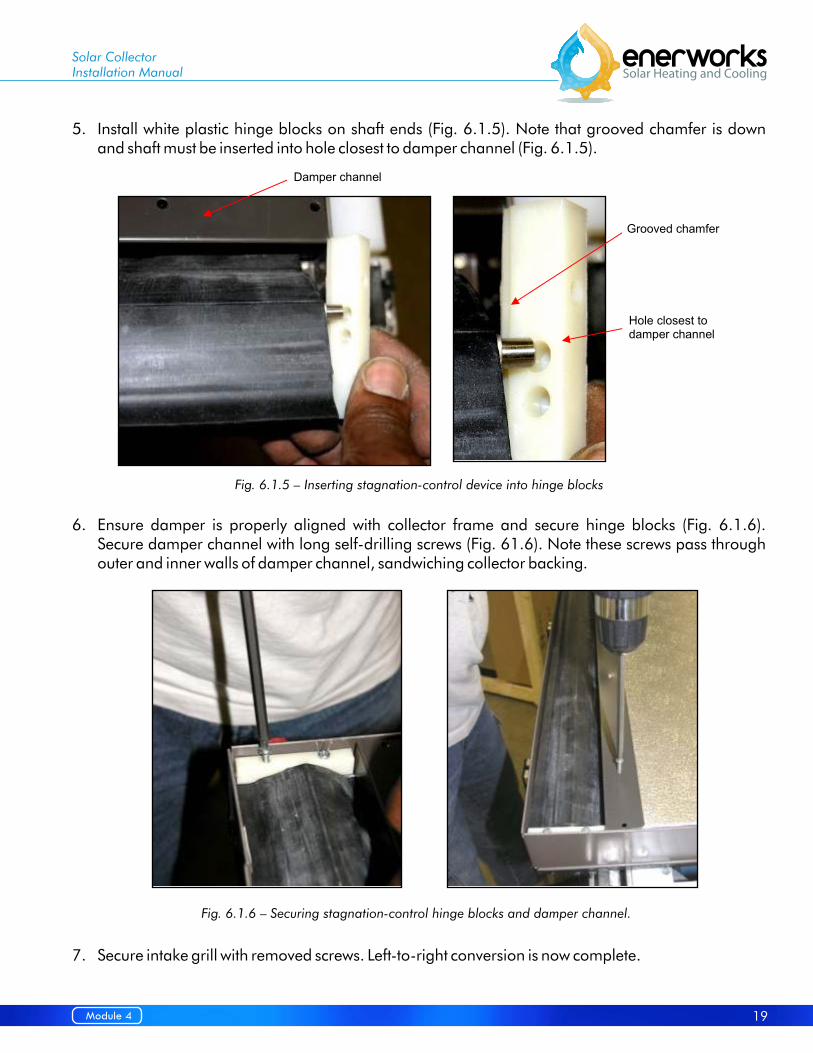
5. Install white plastic hinge blocks on shaft ends (Fig. 6.1.5). Note that grooved chamfer is down and shaft must be inserted into hole closest to damper channel (Fig. 6.1.5).
6. Ensure damper is properly aligned with collector frame and secure hinge blocks (Fig. 6.1.6). Secure damper channel with long self-drilling screws (Fig. 61.6). Note these screws pass through outer and inner walls of damper channel, sandwiching collector backing.
7. Secure intake grill with removed screws. Left-to-right conversion is now complete.
Fig. 6.1.5 – Inserting stagnation-control device into hinge blocks
Fig. 6.1.6 – Securing stagnation-control hinge blocks and damper channel.
Solar CollectorInstallation Manual
19Module 4

6.1.2 Installing Temperature Sensor (Thermistor)
Temperature inside solar collector is monitored by temperature sensor connected via control wire to Energy Station Controller. Temperature sensor is a thermistor, a metal probe whose resistance changes with temperature (nominal 10kΩ @ 77°F, 25°C). See Table 6.1.8 for table of resistance vs. temperature. Thermistor is not pre-installed as only one thermistor is needed per collector array.
Thermistor is installed at upper corner close to roof-penetration. Thermistor kit is included with appliance and contains: Thermistor (with high-temperature resistant Teflon wire insulation), plastic cap with rubber o-ring, two self-drilling hex-head (¼”) screws (Fig. 6.1.7), and two IDCs (Insulation Displacement Connectors, not shown).
1. W i t h a mu l t ime t e r, t e s t t h e r e s i s t an ce o f thermistor. Do not hold bare connections between fingers or you will be measuring resistance through your body and not through thermistor - alligator clips work best.
Check associated temperature from table of resistance vs. temperature (Table 6.1.8). If resistance is not as expected, check meter and connections, and test again.
2. Locate thermistor hole approximately 12” (305 mm) from top of one collector (stagnation-control device is at top) on connection side (label side).
3. Remove rubber cap and carefully cut or punch out foil-covered foam insulation. Be careful not to damage absorber or tube inside collector.
4. With flattened portion of thermistor in-line with collector edge, insert thermistor such that flattened portion seats between absorber plate and internal tube (Fig. 6.1.9). Thermistor will have to be directed towards glass to contact back of absorber plate. Continue to insert until thermistor is seated firmly between absorber plate and internal tube.
Table 6.1.8 – Thermistor resistance vs. temperature.
Fig. 6.1.7 – Thermistor kit.
Solar CollectorInstallation Manual
20 Module 4

5. Insert probe wires through o-ring and black plastic probe cover. Push the cover against the collector frame over the copper end of the probe. Fasten the cover with the two self-drilling screws (Fig.6.1.10).
Mounting brackets secure collectors to C-channel. Two types of mounting brackets are available: hook brackets and L-brackets. Hook brackets are used for mounting to C-channel. L-brackets may be used for rack-mounting (hook brackets may be used for rack-mounting if C-channel is secured to rack). Bracket mounting points are 24” (610 mm) from ends of collector on long sides and 48” (1220 mm) apart, center to center.
Hook Brackets
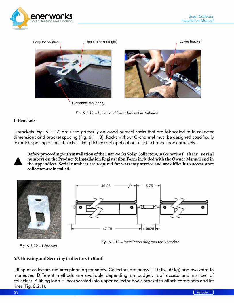
Hook bracket kit consists of upper and lower brackets. Upper hook brackets are left and right specific. Lower brackets are not side specific (Fig. 6.1.11).
Upper brackets feature a unique tab that fits into C-channel to support collector weight before securing. Tab also allows collector to slide, side to side, in C-channel. Upper brackets also feature loops for attaching carabiners and/or line to assist with hoisting. With collector lying flat or on long edge (but not on glass edge), and resting on soft, smooth surface, attach four brackets with bolts and washers (Fig. 6.1.11).
Upper brackets with loop and tab (hook) are towards top (with stagnation-control device). Loops must be closest to top of collector (Fig. 6.1.11). Use ratchet or driver with a ½” socket. Do not overtighten (maximum torque of 9 ft·lb or 12.2 N·m). Lower brackets are towards bottom (with intake grill).
6.1.3 Installing Collector Mounting Brackets
Fig. 6.1.9 – Thermistor seated between absorber and tube.
Fig. 6.1.10 – Thermistor cap.
Solar CollectorInstallation Manual
21Module 4
L-Brackets
L-brackets (Fig. 6.1.12) are used primarily on wood or steel racks that are fabricated to fit collector dimensions and bracket spacing (Fig. 6.1.13). Racks without C-channel must be designed specifically to match spacing of the L-brackets. For pitched roof applications use C-channel hook brackets.
Before proceeding with installation of the EnerWorks Solar Collectors, make note of t h e i r s er i a l numbers on the Product & Installation Registration Form included with the Owner Manual and in the Appendices. Serial numbers are required for warranty service and are difficult to access once collectors are installed.
Lifting of collectors requires planning for safety. Collectors are heavy (110 lb, 50 kg) and awkward to maneuver. Different methods are available depending on budget, roof access and number of collectors. A lifting loop is incorporated into upper collector hook-bracket to attach carabiners and lift lines (Fig. 6.2.1).
6.2 Hoisting and Securing Collectors to Roof
Fig. 6.1.11 – Upper and lower bracket installation.
Fig. 6.1.12 – L-bracket.Fig. 6.1.13 – Installation diagram for L-bracket.
Solar CollectorInstallation Manual
22 Module 4

6.2.1 Ladder Hoist or Shingle-Lift
6.2.2 Scissor Lift or Articulating or Forklift Boom
6.2.3 Scaffolding
Make sure lift can handle collector weight, and can safely reach desired height (Fig. 6.2.2).
These lifts typically require a trained and certified operator. These also provide stable platforms for working on steeply-pitched roofs (Figs. 6.2.2 & 6.2.3).
Scaffolding is inexpensive and very effective for hoisting collectors and for providing a stable work platform, Fig. 6.2.4.
Fig. 6.2.2 – Articulating s boom and scissor lift are all effective tools for hoisting collectors to roof.
hingle-lift
Fig. 6.2.3 – Lifting and securing collectors using forklift boom.
Solar CollectorInstallation Manual
Fig. 6.2.1 – Upper bracket (right) with lifting loop.
Fig. 6.2.4 – Scaffolding used for lifting and as work platform.
23Module 4

6.2.4 Ladder and Lift Line
Using a ladder and lift line is common but requires more than two people. Carabiners and lines should be clipped to lifting loops of upper brackets (Fig. 6.2.5). It is preferable to have two individuals lifting from ground and two on roof to pull collector up and over top of ladder and up and over eave (Fig. 6.2.6).
Collector is not designed to be levered over ladder or eave. Edges of glass and copper connections should be protected from contact with ladders, walls and eaves. Any damage to collector, including broken glass, due to improper handling is not covered by warranty.
It is recommended to have two ladders in place, side by side, to prevent collector from sliding sideways or pivoting around ladder if it is off center. Strapping or securing collector to plywood or boards may facilitate lift and prevent damage.
All individuals working on roofs should have completed a fall-safety course and use appropriate safety techniques and equipment. EnerWorks assumes no liability for injury or death during installation or for any damage caused during installation.
Solar CollectorInstallation Manual
Raise collector against ladder Attach carabiners & lines to loops Hoist & Lift Collector
Fig. 6.2.5 – Lifting collector to roof using ladder and lines.
24 Module 4
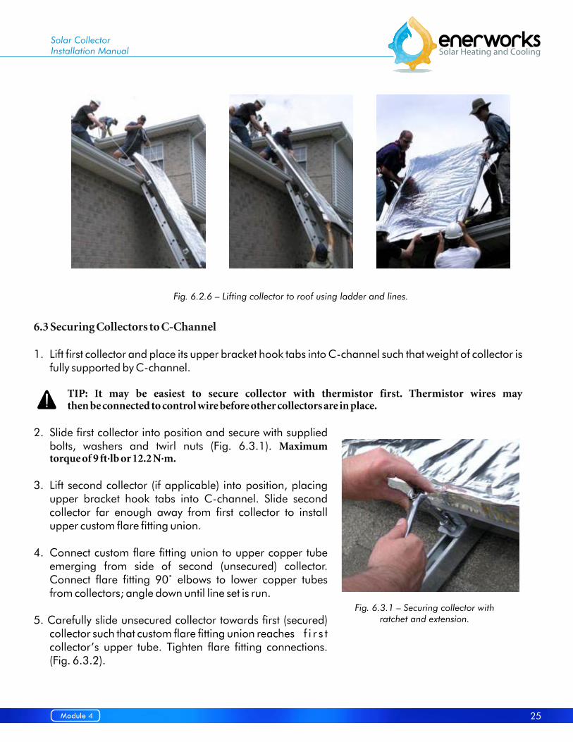
Fig. 6.2.6 – Lifting collector to roof using ladder and lines.
Solar CollectorInstallation Manual
6.3 Securing Collectors to C-Channel
1. Lift first collector and place its upper bracket hook tabs into C-channel such that weight of collector is fully supported by C-channel.
TIP: It may be easiest to secure collector with thermistor first. Thermistor wires may then be connected to control wire before other collectors are in place.
2. Slide first collector into position and secure with supplied bolts, washers and twirl nuts (Fig. 6.3.1). Maximum torque of 9 ft·lb or 12.2 N·m.
3. Lift second collector (if applicable) into position, placing upper bracket hook tabs into C-channel. Slide second collector far enough away from first collector to install upper custom flare fitting union.
4. Connect custom flare fitting union to upper copper tube emerging from side of second (unsecured) collector. Connect flare fitting 90 to lower copper tubes from collectors; angle down until line set is run.
5. Carefully slide unsecured collector towards first (secured) collector such that custom flare fitting union reaches f i r s t collector’s upper tube. Tighten flare fitting connections. (Fig. 6.3.2).
˚ elbows
Fig. 6.3.1 – Securing collector with ratchet and extension.
25Module 4

TIP: Custom flare fitting union is of custom length to allow flashing to slide between collectors. No custom-length fitting is present at lower connections. To ensure collectors are square and not “toed in or out” at bottom, temporarily slide center-flashing between collectors before securing second collector. This will allow for easy installation of center-flashing when appliance commissioning is complete.
6. Secure second collector with supplied bolts, washers and twirl nuts. Maximum torque of 9ft·lb or 12.2 N·m.
7. Follow similar procedure for installing third and fourth collectors if applicable. Threecollector appliances do not have custom flare fitting union between all collectors. Use center-flashing to ensure appropriate spacing if custom flare fitting unions are not present.
EnerWorks Solar Water Heating Appliances are sized with one, two, three or four solar collectors. See EnerWorks Site Evaluation, Appliance Selection and Sizing manual to determine correct size.
Connection procedure:
1. Install collector immediately next to roof-penetration such that line-set can be covered by side-flashing (Fig. 6.4.1).
2. Ca re f u l l y bend l i n e - s e t t o co l l e c t o r connections (if necessary, use a proper tube-bender for tight bends).
3. Cut off excess tube with a proper tube-cutter. Use a light feed to minimize burr, work- harden ing and compress ion o f tube. Remove burr with de-burr or ream tool.
6.4 Collector Configurations
6.4.1 One-Collector Configuration
Fig. 6.3.2 – Custom flare fitting union and 90 elbow connect collectors ˚
Custom flare fitting union Flare fitting 90˚ elbow
Solar CollectorInstallation Manual
Fig. 6.4.1 – One collector configuration.
Flare fitting 90˚ elbow
Roof penetration
Flare fitting 90˚ elbow
26 Module 4

4. Install flare-nuts and flare line-set.
5. Connect flare fitting 90˚ elbows onto line-set and collector tube-ends.
Connection procedure:
1. Procedures in 6.3.
Connection procedure:
1. Position collectors on either side of roof penetration with connection tubes pointing in (Fig 6.4.3). Space each collector 5-3/4” (146 mm) apart. – Alternatively temporarily use center-flashing to achieve correct spacing of panels and secure it to the c-channel.
2. Line set connection from roof penetration to header will require 9 to 11 ft (2743 to 3353 mm), depending on loca t ion o f roof penetration.
6.4.2 Two-Collector Configuration
6.4.3 Three-Collector Configuration
Solar CollectorInstallation Manual
Custom flare fitting union
Roof penetrationFlare fitting 90˚ elbows
Fig. 6.4.2 – Two collectors configuration.
Fig. 6.4.3 – Three collectors configuration.
Flare fitting 90˚ elbows Flare fitting union
Roof penetrationoptions
27Module 4

3. A proper tube-bending tool is required for bends around middle collector.
4. Cut off excess tube with a proper tube-cutter. Use a light feed to minimize burr, work-hardening and compression of tube. Remove burrs with de-burr or ream tool.
5. Install flare-nuts and flare header ends.
6. Connect flare fitting 90˚ elbows onto header ends and collector tube-ends. Do not tighten them.
7. Insulate header tube with supplied 3/8” (9.5 mm) closed cell insulation.
8. With header tube underneath panel connect and tighten flare fitting 90˚ elbows onto line-set and collector tube-ends.
9. Repeat steps 5 to 8 for opposite header tube.
6.4.4 Four-Collector Configuration
Solar CollectorInstallation Manual
Custom flare fitting unions
Roof penetration
Flare fitting 90˚ elbows Flare fitting tees
Fig. 6.4.4 – Four collectors configuration.
Flare fitting 90˚ elbows
28 Module 4

Connection procedure:
1. Position the middle two collectors on either side of roof-penetration with connection tubes pointing out (Fig. 6.4.4). Temporarily use center-flashing to achieve correct spacing of middle collectors and secure them to C-channel.
2. As described in two-collector procedure, install custom flare fitting unions to upper tubes and position and secure outermost collectors.
3. Line-set connections from roof-penetration to flare fitting tees each require 1 – 2 ft. (304.8 mm – 609.6 mm) of tube. Four additional insulated sections of tube, each approximately 5 ft. (1524 mm) in length, are required to connect collectors to push-fitting tees.
4. A proper tube-bending tool is required for tight bends.
5. Cut off excess tube with a proper tube-cutter. Use a light feed to minimize burr, work-hardening and compression of tube. Remove burrs with de-burr or ream tool.
6. Install flare-nuts and flare line-set connections from roof-penetration and additional insulated sections of tube.
7. Connect middle end from the flare fitting tee to line-set from roof penetration. Connect additional insulated tube into each side of the flare fitting tees. Connect f to additional tube ends. Finally, connect f to collector tubes.
1. Cut excess length of control-wire and/or of thermistor wire as needed. Strip about 1½ “ (3- 4 cm) of control-wire sheathing. Do not strip insulation from individual conductor wires.
Thermistor has very large resistance and thus negligible current flow. Only voltage drop across ther mistor is monitored by Control ler. No posit ive or neg ative connections are necessary – either thermistor conductor can be connected to either control wire conductor.
2. Insert one unstripped conductor of control-wire into one of three open holes of IDC. Insert one unstripped thermistor conductor into one of remaining holes. Conductors should be inserted completely. Position should be visible through translucent connector body (Fig. 6.5.1a).
3. To make connection: with slip-joint pliers, squeeze gel-filled blue cap into body of IDC until it clicks and cap is flush with top edge of connector body (Fig. 6.5.1b).
Thermistor wire gauge is 2x22AWG. Control-wire gauge is typically 2x18AWG. Due to small and different w ire gauges, pliers must be used to squeeze IDCs closed and make connections.
lare fitting 90˚ elbows lare fitting 90˚ elbows
6.5 Control-Wire Connections and Line-Set
Solar CollectorInstallation Manual
29Module 4

4. Repeat with second IDC (Fig. 6.5.1c). Ensure wires and connectors are not under tension or exposed to UV light. Excess wire should be taped to fluid line-set to keep it off of roof surface and to limit exposure to moisture.
5. With a proper tube-cutting tool, cut off excess line-set tube, leaving enough to reach upper copper connections of collectors. Use a light feed with tube-cutter to limit burr, work hardening and compression of soft-copper tube. Remove burr with de-burring or ream tool but do not remove material from original wall thickness. Do not allow removed burr material to enter tube.
6. Install 3/8” flare-nuts and flare line-set.
7. Carefully bend line-set tubes down between collectors such that f will reach collector tubes (Fig.6.5.2). A proper tube-bender should be used for tight bends.
8. Connect f onto collector tube-ends. Ensure fittings are tighten.
Do not insulate fittings and do not install collector f l a s h i n g o r l e a f - g u a rd s u n t i l a p p l i a n ce h a s b e e n l e a k - t e s t e d , a n d c h a r g e d a n d pressurized with heat-transfer fluid. Leave plastic foil cover in place until appliance is charged and pressurized with fluid.
7 – Collector Flashing and Leaf-Guard Installation
Collectors must remain covered while charging Appliance with fluid. Uncovered collectors will g e t very hot. Fluid pumped through uncovered collectors will flash boil, placing installer at risk of scalding. Boiling will also damage heat-transfer fluid and void warranty.
Collector flashing and leaf-guard should be installed after leak-testing and after fitting insulation as access to collectors, fittings and thermistor may be necessary if a leak or problem is detected.
Collector flashing and leaf-guard are designed for pitched roof installations only. Flashing and leaf-guard should not be installed on rack-mounted collectors.
lare fitting 90˚ elbows
lare fitting 90˚ elbows
Solar CollectorInstallation Manual
Fig. 6.5.1 – To make thermistor/control-wire connections, insert unstripped conductors into IDC and squeeze with pliers.
Fig. 6.5.2 – connects line-set to collectors (to be insulated after pressurizing
heat-transfer fluid).
Flare fitting 90˚ elbow
Flare fitting 90˚ elbow (to be insulated)
Collector uncovered only after heat-transfer
fluid is pressurized
30 Module 4

7.1 Side-Flashing for 1-Collector Appliances
7.2 Center-Flashing for 2-, 3- and 4-Collector Appliances
One-collector Appliance includes side-flashing that must be installed to cover connections, insulated line-set, thermistor and control wires, and roof-penetration. Side-flashing may be installed on left or right of collector but must cover connections and roof penetration. Side-flashing includes two thin lengths of painted, galvanized steel with 90° bends and two end-caps for top and bottom (Fig. 7.1).
Two sets of side-flashing may be installed to make installation symmetrical. Side-flashing may also be used on multi-collector installations to hide C-channel.
1. Insert edge of side-flashing piece in collector side-wall groove. Align bottom edge of flashing with bottom of collector. Secure lower side-flashing to roof with included roofing screws.
2. Insert edge of upper side-flashing into side-wall groove such that it overlaps lower section (for shedding rain and snow ). Secure upper side-flashing to roof with included roofing screws.
3. Insert rectangular caps into upper and lower holes created by side-flashing and collector (Fig. 7.1.1). Secure to roof with included roofing screws. Secure to upper and lower side-flashing with included self-drilling screws.
4. Secure upper side-flashing section to lower section at overlap with included self-drilling screws.
Two-, three- and four-collector Appliances include one, two or three sets of center-flashing. Center-flashing should cover insulated line-set, collector connections, thermistor and control wires and roof penetration. Center-flashing is two thin lengths of painted, galvanized steel that slide between collectors. Side-flashing may also be used on multi-collector installations to hide C-channel.
Solar CollectorInstallation Manual
Fig. 7.1.1 – Collector side-flashing. Note roof-penetration boot under side-flashing.
31Module 4

1. Slide center-flashing between collectors in collector side-wall grooves. Upper length should overlap lower length to ensure proper rain and snow shedding (Fig. 7.2.1).
2. Fold ends of center-flashing sections down such that they are flush with collector side-wall edge. Secure center-flashing sections to upper and lower side-walls with self-drilling screws. If leaf-guard is to be installed, do not fold down upper center-flashing length until leaf-guard is in place (Fig. 7.2.2).
3. Secure upper center-flashing section to lower section with a self-drilling screw (Fig. 7.2.1).
TIP: If it is difficult to slide center flashing between collectors, try loosening C-channel bolts temporarily. Be sure to re-tighten C-channel bolts after center-flashing is “started” in side-wall grooves. It may also help to bow the center flashing sections slightly upwards to get them “started” in the side-wall grooves.
Fig. 7.2.1 – Center-flashing slides between collectors (2-, 3- and 4-collector Appliances).
Fig. 7.2.2 – Center-flashing folds down flush with edge of collector (2, 3 and 4-collector Appliances).
Solar CollectorInstallation Manual
32 Module 4

7.3 Leaf-Guard Installation
Leaf-guard is included with three- and four-collector Appliances to protect and shade insulated line-set. Leaf-guard for one- and two-collector Appliances is optional and is of benefit to prevent leaves and debris from gathering around and beneath collectors. Leaf-guard includes thin lengths of perforated, painted, galvanized steel and triangular end-caps. Perforations ensure proper functioning of patented stagnation control device. Each section of leaf-guard is slightly longer than collector is wide.
1. Insert lower edge of leaf-guard section into side-wall groove at top of collector. Align side edge of leaf-guard section with outer side of collector or with side-flashing. Leaf-guard sections are overlapped to ensure edges are flush with outer collector side-walls.
2. Secure leaf-guard to roof with included roofing screws.
3. Insert triangular caps into left and right leaf-guard ends. Secure end caps to roof with included roofing screws (Fig. 7.3.1).
4. Secure end-caps to leaf-guard sections and secure sections to each other at overlaps with self-drilling screws.
5. Bend center-flashing down to leaf-guard and secure with self-drilling screws if applicable (Fig. 7.3.1).
Fig. 7.3.1 – Two collectors with center-flashing and leaf-guard.
Solar CollectorInstallation Manual
33Module 4

En
erW
ork
s In
c. -
969 J
ulia
na
Dri
ve, W
ood
stock
, O
N
N4V
1C
1, C
an
ad
a, T
el:
(519)
268-6
500
T
oll-f
ree:
1-8
77-2
68-6
502
Fa
x:
(519)
268-6
292
ww
w.e
nerw
ork
s.co
m


Tools and Supplies Note
fall-prevention/fall-arrest equipment observe all local requirements
ladders or scaffolding
rope and carabiners for hoisting collectors/supplies
sturdy bag or basket for hoisting tools/supplies
w ork lamps for attic
drill w ith charger and extra battery or extension cord
¼” drill bit (long, min. 6” or 12" bit required) to pre-drill rafters for lag-bolts
¼” driver bit for roofing, thermistor cap screw s
5/16” driver bit for f lashing screw s
caulking gun for roof sealant
extra roof sealant (polyurethane/silicone)
level
measuring tape
hole saw to make 2 x 1 ¼” or one 2.5” hole
hammer / small pry bar
chalk or tape w ith marker
slip-joint pliers for thermistor w ire IDCs (insulation displacement connectors)
spray bottle w ith dish soap solution for leak testing
Multimeter to test thermistors, see pg X for temp. vs. resistance table
insulation tape for taping insulation seams
pipe-cutter
de-burr (ream) tool to de-burr copper tupe
3/8" tube-bender for tight bends (necessary for 3 & 4-collector Appliances)
copper clips/pipe straps for securing line-set
UV protection/w rap for exposed insulation to protect line-set
false dow nspout/electrical conduit/pvc/abs exterior conduit for line-set
extra spacers, lag-bolts, w ashers, roofing screw s, etc.
f ire extinguisher observe all local requirements
safety glasses observe all local requirements
steel-toed boots observe all local requirements
w ork gloves observe all local requirements
fall-prevention/fall-arrest equipment observe all local requirements
Safe
ty
þ
For
Lin
e-S
et&
Colle
cto
rIn
sta
llatio
n
Open-ended w rench, ratcheting box-end w rench, ratchet
w ith extension, and or nut driver (1/2” and 9/16”)for securing C-channel and collectors
969 Juliana Drive, Woodstock, ON N4V 1C1, CanadaTel: (519) 268-6500 Toll-free: 1-877-268-6502
Fax: (519) 268-6292 www.enerworks.com© 2013 enerworks