software synthesis and code generation for signal - drum
TRANSCRIPT

Software Synthesis and Code Generation
for Signal Processing SystemsShuvra S. Bhattacharyya
University of MarylandDepartment of Electrical and Computer Engineering
College Park, MD 20742, USA
Rainer Leupers, Peter Marwedel
University of DortmundDepartment of Computer Science 12
44221 Dortmund, Germany
ABSTRACT
The role of software is becoming increasingly important in the implementation of DSP applications. As this trend in-
tensifies, and the complexity of applications escalates, we are seeing an increasedneed for automated tools to aid in the
development of DSP software. This paper reviews the state of the art inprogramming language and compiler technology
for DSP software implementation. In particular, we review techniques for high level, block-diagram-based modeling of
DSP applications; the translation of block diagram specifications into efficient C programs using global, target-independent
optimization techniques; and the compilation of C programs into streamlined machine code for programmable DSP proces-
sors, using architecture-specific and retargetable back-end optimizations. In our review, we also point out some important
directions for further investigation.
1 Introduction
Although dedicated hardware can provide significant speed and power consumption advantages for signal processing appli-
cations [1], extensive programmability is becoming an increasingly desirable feature of implementation platforms for VLSI
signal processing. The trend towards programmable platforms is fueledby tight time-to-market windows, which in turn result
from intense competition among DSP product vendors, and from the rapid evolution of technology, which shrinks the life
cycle of consumer products. As a result of short time-to-market windows, designers are often forced to begin architecture
design and system implementation before the specification of a product is fully completed. For example, a portable com-
munication product is often designed before the signal transmission standards under which it will operate are finalized, or
before the full range of standards that will be supported by the product is agreed upon. In such an environment, late changes
in the design cycle are mandatory. The need to quickly make such late changes requires the use of software. Furthermore,
whether or not the product specification is fixed beforehand, software-based implementations using off-the-shelf processors
take significantly less verification effort compared to custom hardware solutions.
Although the flexibility offered by software is critical in DSP applications, the implementation of production quality DSP
software is an extremely complex task. The complexity arises from the diversity of critical constraints that must be satisfied;
typically these constraints involve stringent requirements on metricssuch as latency, throughput, power consumption, code
size, and data storage requirements. Additional constraints include theneed to ensure key implementation properties such asTechnical report UMIACS-TR-99-57, Institute for AdvancedComputer Studies, University of Maryland, College Park, 20742, September, 1999. S. S.
Bhattacharyya was supported in this work by the US National Science Foundation (CAREER, MIP9734275) and Northrop Grumman Corp. R. Leupers and
P. Marwedel were supported by HP EESof, California.
1

bounded memory requirements and deadlock-free operation. As a result, unlike developers of software for general-purpose
platforms, DSP software developers routinely engage in meticulous tuning and simulation of program code at the assembly
language level.
Important industry-wide trends at both the programming language level and the processor architecture level have had
a significant impact on the complexity of DSP software development. Atthe architectural level, a specialized class of mi-
croprocessors has evolved that is streamlined to the needs of DSP applications. These DSP-oriented processors, called
programmable digital signal processors (PDSPs), employ a variety of special-purpose architectural features that support com-
mon DSP operations such as digital filtering, and fast Fourier transforms [2, 3, 4]. At the same time, they often exclude
features of general purpose processors, such as extensive memory management support, that are not important for many DSP
applications.
Due to various architectural irregularities in PDSPs, which are requiredfor their exceptional cost/performance and
power/performance trade-offs [2], compiler techniques for general-purpose processors have proven to be inadequate for ex-
ploiting the power of PDSP architectures from high level languages [5].As a result, the code quality of high-level procedural
language (such as C) compilers for PDSPs has been several hundreds of percent worse than manually-written assembly
language code [6, 52]. This situation has necessitated the widespread use of assembly-language coding, and tedious perfor-
mance tuning, in DSP software development. However, in recent years, a significant research community has evolved that is
centered around the development of compiler technology for PDSPs. This community has begun to narrow the gap between
compiler-generated code and manually optimized code.
It is expected that innovative processor-specific compilation techniques for PDSPs will provide a significant productivity
boost in DSP software development, since such techniques will us allowto take the step from assembly programming of
PDSPs to the use of high-level programming languages. The key approach to reduce the overhead of compiler-generated
code is the development of DSP-specific compiler optimization techniques. While classical compiler technology is often
based on the assumption of a regular processor architecture, DSP-specific techniques are designed to be capable of exploiting
the special architectural features of PDSPs. These include special purpose registers in the data path, dedicated memory
address generation units, and a moderate degree of instruction-level parallelism.
To illustrate this, consider the architecture of a popular fixed-pointDSP (TI TMS320C25) in fig. 1. Its data path com-
prises the registers TR, PR, and ACCU, each of which plays a specific role in communicating values between the functional
units of the processor. This structure allows for a very efficient implementation of DSP algorithms (e.g. filtering algo-
rithms). More regular architectures (e.g. with general-purpose registers) would, for instance, require more instruction bits for
addressing the registers and more power for reading and writing the register file.
From a compiler viewpoint, the mapping of operations, program variables, and intermediate results to the data path in
fig. 1 must be done in such a way, that the amount of data transfer instructions between the registers is minimized. The address
generation unit (AGU) comprises a special ALU and is capable of performing address arithmetic in parallel to the central data
path. In particular, it provides parallel auto-increment instructions for address registers. As we will show later, exploitation
of this feature in a compiler demands for an appropriate memory layout of program variables. Besides the AGU, also the
data path offers a certain degree of instruction-level parallelism. For instance, loading a memory value into register TR and
accumulating a product stored in PR can be performed in parallel within a single machine instruction. Since such parallelism
cannot be explicitly described in programming languages like C, compilers need to carefully schedule the generated machine
instructions, so as to exploit the potential parallelism and to generatefast and dense code.
Further architectural features frequently present in PDSPs include parallel memory banks (providing higher memory
access bandwidth), chained operations (such as multiply-accumulate), special arithmetic operations (such as addition with
saturation), and mode registers (for switching between different arithmetic modes).
For most of the architectural features mentioned above, dedicated code optimization techniques have been developed
recently, an overview of which will be given in section 3. Many of these optimizations are computationally complex, resulting
2

in a comparatively low compilation speed. This is intensified by the fact that compilers for PDSPs, besides the need for
specific optimization techniques, have to deal with thephase coupling problem. The compilation process is traditionally
divided into the phases of code selection, register allocation, and instruction scheduling, which have to be executed in a
certain order. For all possible phase orders, the approach of separate compilation phases results in a code quality overhead,
since each phase may impose obstructing constraints on subsequent phases,which would not have been necessary from a
global viewpoint. While for regular processor architectures like RISCs this overhead is moderate and thus tolerable, it is
typically much higher for irregular processor architectures as found in PDSPs. Therefore, it is desirable to perform the
compilation phases in a coupled fashion, where the different phases mutually exchange information so as to achieve a global
optimum.
Even though phase-coupled compiler techniques lead to a further increase in compilation time, it is widely agreed in
the DSP software developer community that high compilation speed is ofmuch lower concern than high code quality. Thus,
compilation times of minutes or even hours may be perfectly acceptable in manycases. This fact gives good opportunities
for novel computation-intensive approaches to compiling high level languages for PDSPs, which however would not be
acceptable in general-purpose computing.
Besides pure code optimization issues, the large variety of PDSPs (both standard ”off-the-shelf” processors and appli-
cation specific processors) currently in use create a problem of economic feasibility of compiler construction. Since code
optimization techniques for PDSPs are highly architecture-specific by nature, a huge amount of different optimization tech-
niques were required to build efficient compilers for all PDSPs available on the market. Therefore, in this paper we will also
briefly discuss techniques forretargetable compilation. Retargetable compilers are capable of generating code not only for a
single target processor but for a class of processors, thereby reducing the number of compilers required. This is achieved by
providing the compiler with a description of the machine for which code is to be generated, instead of hard-coding the ma-
chine description in the compiler. We will mention different approaches of processor modeling for retargetable compilation.
Retargetability permits to quickly generate compilers for new processors. If the processor description formalism is flexible
enough, then retargetable compilers may also assist in customizing an only partially predefined processor architecture for a
given application.
At the system specification level, the past several years have seen increased useof block-diagram based, graphical
programming environments for digital signal processing. Such graphical programming environments, which enable DSP
systems to be specified as hierarchies of block diagrams, offer several important advantages. Perhaps the most obvious of
these advantages is their intuitive appeal. Although visual programming languages have seen limited use in many application
domains, DSP system designers are used to thinking of systems in termsof graphical abstractions, such as signal flow
diagrams, and thus, block diagram specification via a graphical user interface is a convenient and natural programming
interface for DSP design tools.
An illustration of a block diagram DSP system, developed using the Ptolemy design environment [7], is shown in fig. 2.
This is an implementation of a discrete wavelet transform [8] application. The top part of the figure shows the highest level
of the block diagram specification hierarchy. Many of the blocks in the specification arehierarchical, which means that the
internal functionality of the blocks are also specified as block diagrams (“nested” block diagrams). Blocks at the lowest level
of the specification hierarchy, such as the individual FIR filters, are specified in a meta-C language (C augmented with special
constructs for specifying block parameters and interface information).
In addition to offering intuitive appeal, the specification of systems in terms of connections between pre-defined, en-
capsulated functional blocks naturally promotes desirable software engineering practices such as modularity and code reuse.
As the complexity of applications increases continually while time-to-market pressures remain intense, reuse of design effort
across multiple products is becoming more and more crucial to meeting development schedules.
In addition to their syntactic and software engineering appeal, there are a number of more technical advantages of graph-
ical DSP tools. These advantages hinge on the use of appropriate models of computation to provide the precise underlying
3

block diagram semantics. In particular, the use ofdataflow modelsof computation can enable the application of powerful
verification and synthesis techniques. Broadly speaking, dataflow modelinginvolves representing an application as a directed
graph in which the graph vertices represent computations and edges represent logical communication channels between com-
putations. Dataflow-based graphical specification formats are used widely in commercial DSP design tools such as COSSAP
by Synopsys, the Signal Processing Worksystem by Cadence, and the Advanced Design System by Hewlett-Packard. These
three commercial tools all employ thesynchronous dataflowmodel [9], the most popular variant of dataflow in existing
DSP design tools. Synchronous dataflow specification allows bounded memory determination and deadlock detection to be
performed comprehensively and efficiently at compile time. In contrast, bothof these verification problems are in general
impossible to solve (in finite time) for general purpose programming languages such as C.
Potentially the most useful benefit of dataflow-based graphical programming environments for DSP is that carefully-
specified graphical programs can expose coarse-grain structure of the underlying algorithm, and this structure can be exploited
to improve the quality of synthesized implementations in a wide variety of ways. For example, the process of scheduling —
determining the order in which the computations in an application will execute — typically has a large impact on all of the
key implementation metrics of a DSP system. A dataflow-based system specification exposes high-level scheduling flexibility
that is often not possible to deduce manually or automatically from an assembly language or high-level procedural language
specification. This scheduling flexibility can be exploited by a synthesis tool to streamline an implementation based on the
given set of performance and cost constraints. We will elaborate on dataflow-based scheduling in sections 2.1.2 and 2.2.
Although graphical dataflow-based programming tools for DSP have become increasingly popular in recent years, the
use of these tools in industry is largely limited to simulation and prototyping. The quality of today’s graphical programming
tools is not sufficient to consistently deliver production-quality implementations. As with procedural language compilation
technology for PDSPs, synthesis from dataflow-based graphical specifications offers significant promise for the future, and is
an important challenge confronting the DSP design and implementation research community today. Furthermore, these two
forms of compiler technology are fully complementary to one another: themixture of dataflow and C (or any other procedural
language), as described in the example of fig. 2, is an especially attractive specification format. In this format, coarse-grain
“subprogram” interactions are specified in dataflow, while the functionality of individual subprograms is specified in C. Thus,
dataflow synthesis techniques optimize the final implementation at the inter-subprogram level, while C compiler technology
is required to perform fine-grained optimization within subprograms.
This paper motivates the problem of compiler technology development forDSP software implementation, provides a
tutorial overview of modeling and optimization issues that are involved in the compilation of DSP software, and provides
a review of techniques that have been developed by various researchers to address some of these issues. The first part of
our overview focuses on coarse-grain software modeling and optimizationissues pertinent to the compilation of graphical
dataflow programs, and the second part focuses on fine-grained issues that arise in the compilation of high level procedural
languages such as C.
These two levels of compiler technology (coarse-grain and fine grain) are commonly referred to assoftware synthesis
andcode generation, respectively. More specifically, by software synthesis, we mean the automated derivation of a software
implementation (application program) in some programming language given a library of subprogram modules, a subset
of selected modules from this library, and a specification of how these selectedmodules interact to implement the target
application. Fig. 2 is an example of a program specification that is suitable for software synthesis. Here, synchronous
dataflow semantics are used to specify subprogram interactions. In section 2.2, we explore software synthesis issues for DSP.
On the other hand, code generation refers to the mapping of a software implementation in some programming language
to an equivalent machine program for a specific programmable processor. Thus, the mapping of a C program on to the specific
resources of the datapath in fig. 1 is an example of code generation. We explore DSP code generation technology in section
3.
4

2 Compilation of dataflow programs to application programs
2.1 Dataflow modeling of DSP systems
To perform simulation, formal verification, or any kind of compilationfrom block-diagram DSP specifications, a precise set
of semantics is needed that defines the interactions between different computational blocks in a specification. Dataflow-based
computational models have proven to provide block-diagram semantics that are both intuitive to DSP system designers, and
efficient from the point of view of verification and synthesis.
In the dataflow paradigm, a computational specification is represented as a directed graph. Vertices in the graph (called
actors) correspond to the computational modules in the specification. In most dataflow-based DSP design environments,
actors can be of arbitrary complexity. Typically, they range from elementary operations such as addition or multiplication to
DSP subsystems such as FFT units or adaptive filters.
An edge(v1; v2) in a dataflow graph represents the communication of data fromv1 to v2. More specifically, an edge
represents a FIFO (first-in-first-out) queue that buffers data samples(tokens) as they pass from the output of one actor to the
input of another. Ife = (v1; v2) is a dataflow edge, we writesrc(e) = v1, andsnk(e) = v2. When dataflow graphs are
used to represent signal processing applications, a dataflow edgee has a non-negative integer delaydel (e) associated with
it. The delay of an edge gives the number of initial data values that are queuedon the edge. Each unit of dataflow delay is
functionally equivalent to thez1 operator: the sequence of data valuesfyng generated at the input of the actorsnk(e) is
equal to the the shifted sequencefxndel(e)g, wherefxng is the data sequence generated at the output of the actorsrc(e).2.1.1 Consistency
Under the dataflow model, an actor can execute at any time that it has sufficient dataon all input edges. An attempt to execute
an actor when this constraint is not satisfied is said to causebuffer underflowon all edges that do not contain sufficient data.
For dataflow modeling to be useful for DSP systems, the execution of actors must also accommodate input data sequences
of unbounded length. This is because DSP applications often involve operations that are applied repeatedly to samples in
indefinitely long input signals. For an implementation of a dataflow specification to be practical, the execution of actors must
be such that the number of tokens queued on each FIFO buffer (dataflow edge) must remain bounded throughout the execution
of the dataflow graph. In other words, there should not beunbounded data accumulationon any edge in the dataflow graph.
In summary, executing a dataflow specification of a DSP system involves twofundamental, processor-independent re-
quirements — avoiding buffer underflow and avoiding unbounded data accumulation (buffering). The dataflow model im-
poses no further constraints on the sequence in which computations (actors) are executed. On the other hand, in procedural
languages, such as C and FORTRAN, the ordering of statements as well as the use of control-flow constructs imply sequenc-
ing constraints beyond those that are required to satisfy data dependencies. By avoiding theoverspecificationof execution
ordering, dataflow specifications provide synthesis tools with full flexibility to streamline the execution order to match the
relevant implementation constraints and optimization objectives. This feature of dataflow is of critical importance for DSP
implementation since, as we will see throughout the rest of this section, the execution order has a large impact on most
important implementation metrics, such as performance, memory requirements, and power consumption.
The term “consistency” refers to the two essential requirements of DSP dataflow specifications — the absence of over-
flow and unbounded data accumulation. We say that aconsistentdataflow specification is one that can be implemented
without any chance of buffer underflow or unbounded data accumulation (regardless of the input sequences that are applied to
the system). If there exist one or more sets of input sequences for which underflow and unbounded buffering are avoided, and
there also exist one or more sets for which underflow or unbounded buffering results, we say that a specification ispartially
consistent. A dataflow specification that is neither consistent nor partially consistentis called aninconsistent specification.
More elaborate forms of consistency based on a probabilistic interpretation of token flow are explored in [10].
5

Clearly, consistency is a highly desirable property for DSP softwareimplementation. For most consistent dataflow
graphs, tight bounds can be derived on the numbers of data values that coexist (data that has been produced but not yet
consumed) on the individual edges (buffers). For such graphs, all buffer memory allocation can be performed statically, and
thus, the overhead of dynamic memory allocation can be avoided entirely. This is a valuable feature when attempting to
derive a streamlined software implementation.
2.1.2 Scheduling
A fundamental task in synthesizing software from an SDF specification is that of scheduling, which refers to the process of
determining the order in which the actors will be executed. Scheduling iseither dynamic or static. Instatic scheduling, the
actor execution order is specified at synthesis time, and is fixed – in particular, the order is not data-dependent. To be useful
in handling indefinitely long input data sequences, a static schedule must be periodic. A periodic, static schedule can be
implemented in a finite amount of program memory space by encapsulating theprogram code for one period of the schedule
within an infinite loop. Indeed, this is how such schedules are most often implemented in practice.
In dynamic scheduling, the sequence of actor executions (schedule) is not specified during synthesis, and run-time
decision-making is required to ensure that actors are executed only when their respective input edges have sufficient data.
Disadvantages of dynamic scheduling include the overhead (execution timeand power consumption) of performing schedul-
ing decisions at run-time, and decreased predictability, especially in determining whether or not any relevant real-time con-
straints will be satisfied. However, if the data production/consumption behavior of individual actors exhibits significant data-
dependence, then dynamic scheduling may be required to avoid buffer underflow and unbounded data accumulation. Further-
more, if the performance characteristics of actors are impossible to estimate accurately, then effective dynamic scheduling
leads to better performance by adaptively streamlining the schedule evolution to match the dynamic characteristics of the
actors.
For most DSP applications, including the vast majority of applications that are amenable to the SDF model mentioned in
section 1, actor behavior is highly predictable. For such applications, given the tight cost and power constraints that are typical
of embedded DSP applications, it is highly desirable to avoid dynamic scheduling overhead as much as possible. The ultimate
goal under such a high level of predictability is a (periodic) static schedule. If it is not possible to construct a static schedule,
then it is desirable to identify “maximal” subsystems that can be scheduled statically, and use a small amount of dynamic
decision-making to coordinate the execution of these statically-scheduled subsystems. Schedules that are constructed using
such a hybrid, mostly static approach are calledquasi-static schedules.
2.1.3 Synchronous dataflow
A dataflow computation modelcan be viewed as a subclass of dataflow graph specifications. A wide variety of dataflow
computational models can be conceived depending on restrictions that are imposed on the manner in which dataflow actors
consume and produce data. For example,synchronous dataflow (SDF), which is the simplest and currently the most popular
form of dataflow for DSP, imposes the restriction that the number of data values produced by an actor onto each output edge
is constant, and similarly the number of data values consumed by an actor from each input edge is constant. Thus, an SDF
edgee has two additional attributes — the number of data values produced ontoe by each invocation of the source actor,
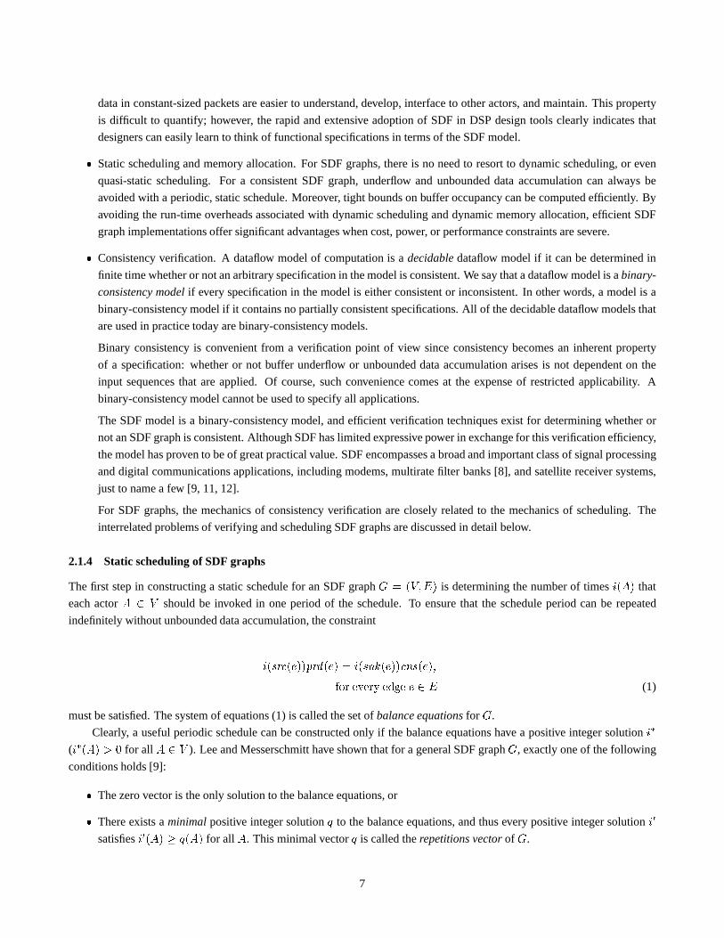
denotedprd (e), and the number of data values consumed frome by each invocation of the sink actor, denotedcns(e).The example shown in fig. 2 conforms to the SDF model. An SDF abstraction of a scaled-down and simplified version
of this system is shown in fig. 3. Here each edge is annotated with the number of data values produced and consumed by the
source and sink actors, respectively. For example,prd((B;C)) = 1, andcns((B;C)) = 2.
The restrictions imposed by the SDF model offer a number of importantadvantages. Simplicity. Intuitively, when compared to more general types of dataflow actors, actors that produce and consume
6
data in constant-sized packets are easier to understand, develop, interface to other actors, and maintain. This property
is difficult to quantify; however, the rapid and extensive adoption of SDF in DSP design tools clearly indicates that
designers can easily learn to think of functional specifications in terms of the SDF model. Static scheduling and memory allocation. For SDF graphs, there is no need to resort to dynamic scheduling, or even
quasi-static scheduling. For a consistent SDF graph, underflow and unbounded data accumulation can always be
avoided with a periodic, static schedule. Moreover, tight bounds on buffer occupancy can be computed efficiently. By
avoiding the run-time overheads associated with dynamic scheduling anddynamic memory allocation, efficient SDF
graph implementations offer significant advantages when cost, power, or performance constraints are severe. Consistency verification. A dataflow model of computation is adecidabledataflow model if it can be determined in
finite time whether or not an arbitrary specification in the model is consistent. We say that a dataflow model is abinary-
consistency modelif every specification in the model is either consistent or inconsistent. In other words, a model is a
binary-consistency model if it contains no partially consistent specifications. All of the decidable dataflow models that
are used in practice today are binary-consistency models.
Binary consistency is convenient from a verification point of view sinceconsistency becomes an inherent property
of a specification: whether or not buffer underflow or unbounded data accumulation arises is not dependent on the
input sequences that are applied. Of course, such convenience comes at the expenseof restricted applicability. A
binary-consistency model cannot be used to specify all applications.
The SDF model is a binary-consistency model, and efficient verification techniques exist for determining whether or
not an SDF graph is consistent. Although SDF has limited expressive power in exchange for this verification efficiency,
the model has proven to be of great practical value. SDF encompasses a broad and important class of signal processing
and digital communications applications, including modems, multiratefilter banks [8], and satellite receiver systems,
just to name a few [9, 11, 12].
For SDF graphs, the mechanics of consistency verification are closely related to the mechanics of scheduling. The
interrelated problems of verifying and scheduling SDF graphs are discussed in detail below.
2.1.4 Static scheduling of SDF graphs
The first step in constructing a static schedule for an SDF graphG = (V;E) is determining the number of timesi(A) that
each actorA 2 V should be invoked in one period of the schedule. To ensure that the schedule period can be repeated
indefinitely without unbounded data accumulation, the constrainti(src(e))prd (e) = i(snk(e))cns(e);for every edge e 2 E (1)
must be satisfied. The system of equations (1) is called the set ofbalance equationsfor G.
Clearly, a useful periodic schedule can be constructed only if the balance equations have a positive integer solutioni(i(A) > 0 for all A 2 V ). Lee and Messerschmitt have shown that for a general SDF graphG, exactly one of the following
conditions holds [9]: The zero vector is the only solution to the balance equations, or There exists aminimalpositive integer solutionq to the balance equations, and thus every positive integer solutioni0satisfiesi0(A) q(A) for all A. This minimal vectorq is called therepetitions vectorof G.
7

If the former condition holds, thenG is inconsistent. Otherwise, a bounded buffer periodic schedule can be constructed
provided that it is possible to construct a sequence of actor executions such that buffer underflow is avoided, and each actorA is executed exactlyq(A) times. Given a consistent SDF graph, we refer to an execution sequence that satisfies these
two properties as avalid schedule period, or simply avalid schedule. Clearly, a bounded memory static schedule can be
implemented in software by encapsulating the implementation of any valid schedule within an infinite loop.
A linear-time (O(j V j + j E j)) algorithm to determine whether or not a repetitions vector exists, andto compute a
repetitions vector whenever one does exist can be found in [11].
For example, consider the SDF graph shown in fig. 3. The repetitions vector components for this graph are given byq(A) = q(B) = q(P ) = q(Q) = 4q(C) = q(D) = q(E) = q(H) = q(M) = q(N) = q(O) = 2q(F ) = q(G) = q(I) = q(J) = q(K) = q(L) = 1 (2)
If a repetitions vector exists for an SDF graph, but a valid schedule doesnot exist, then the graph is said to bedeadlocked.
Thus, an SDF graph is consistent if and only if a repetitions vector exists, and the graph is not deadlocked. In general, whether
or not a graph is deadlocked depends on the edge delaysfdel(e) j e 2 Eg as well the production and consumption parametersfsrc(e)g andfsnk(e)g. An example of a deadlocked SDF graph is given in fig. 4. An annotation of the formnD next to an
edge in the figure represents a delay ofn units. Note that the repetitions vector for this graph is given byq(A) = 3; q(B) = 2; q(C) = 1: (3)
Once a repetitions vectorq has been computed, deadlock detection and the construction of a valid schedule canbe
performed concurrently. Premature termination of the scheduling procedure — termination before each actorA has been
fully scheduled(scheduledq(A) times) — indicates deadlock. One simple approach is to schedule actor invocations one
at a time and simulate the buffer activity in the dataflow graph accordinglyuntil all actors are fully scheduled. The buffer
simulation is necessary to ensure that buffer overflow is avoided. A pseudocode specification of this simple approach can
be found in [11]. Lee and Messerschmitt show that this approach terminatesprematurely if and only if the input graph is
deadlocked, and otherwise, regardless of the specific order in which actors areselected for scheduling, a valid schedule is
always constructed [13].
In summary, SDF is currently the most widely-used dataflow model in commercial and research-oriented DSP design
tools. Commercial tools that employ SDF semantics include Simulink byThe Math Works, SPW by Cadence, and HP
Ptolemy by Hewlett Packard. SDF-based research tools include Gabriel [14] and several key domains in Ptolemy [7], from
from U.C. Berkeley; and ASSIGN from Carnegie Mellon [15]. The SDF model offers efficient verification of consistency
for arbitrary specifications, and efficient construction of static schedules for all consistent specifications. Our discussion
above outlined a simple, systematic technique for constructing a static schedule whenever one exists. In practice, however,
it is preferable to employ more intricate scheduling strategies that takecareful account of the costs (performance, memory
consumption, etc.) of the generated schedules. In section 2.2, we will discuss techniques for streamlined scheduling of SDF
graphs based on the constraints and optimization objectives of the targetedimplementation. In the remainder of this section,
we discuss a number of useful extensions to the SDF model.
2.1.5 Cyclo-static dataflow
Cyclo-static dataflow (CSDF) and scalable synchronous dataflow (described in section 2.1.6) are presently the most widely-
used extensions of SDF. In CSDF, the number of tokens produced and consumed by an actor is allowed to vary as long the
8

variation takes the form of a fixed, periodic pattern [16, 17]. More precisely, each actor A in a CSDF graph has associ-
ated with it afundamental period(A) 2 f1; 2; : : :g, which specifies the number ofphasesin one minimal period of the
cyclic production/consumption pattern ofA. For each input edgee to A, the scalar SDF attributecns(e) is replaced by a(A)-tupleCe;1; Ce;2; : : : ; Ce;(A), where eachCe;i is a nonnegative integer that gives the number of data values consumed
from e by A in the ith phase of each period ofA. Similarly, for each output edgee, prd(e) is replaced by a(A)-tuplePe;1; Pe;2; : : : ; Pe;(A), which gives the numbers of data values produced in successive phases ofA.
A simple example of a CSDF actor is illustrated in fig. 5(a). This actor is a conventionaldownsampleractor (with
downsampling factor 3) from multirate signal processing. Functionally, a downsampler, performs the functiony[i] = x[N(i1) + 1], where fork = 1; 2; : : :, y[k] andx[k] denote thek data values produced and consumed, respectively. Thus, for every
input value that is copied to the output,N 1 input values are discarded. As shown in fig. 5(b) forn = 3, this functionality
can be specified by a CSDF actor that hasN phases. A data value is consumed on the input for allN phases, resulting in
theN -componentconsumption tuple(1; 1; : : : ; 1); however, a data value is produced onto the output edge only on the first
phase, resulting in theproduction tuple(1; 0; 0; : : : ; 0).Like SDF, CSDF is a binary consistency model, and it is possible to perform efficient verification of bounded memory
requirements and buffer underflow avoidance for CSDF graphs [17]. Furthermore, static schedules can always be constructed
for consistent CSDF graphs.
A CSDF actorA can easily be converted into an SDF actorA0 such that if identical sequences of input data values are
applied toA andA0, then identical output data sequences result. Such afunctionally equivalentSDF actorA0 can be derived
by having each invocation ofA0 implement one fundamental CSDF period ofA (that is,(A) successive phases ofA). Thus,
for each input edgee0 of A0, the SDF parameters ofe0 are given by del (e0) = del(e), prd (e0) =P(A)i=1 Pe;i, and cns(e0) =P(A)i=1 Ce;i,wheree is the corresponding input edge to the CSDF actorA. Applying this conversion to the downsampler example
discussed above gives an “SDF equivalent” downsampler that consumes a block of N input data values on each invocation,
and produces a single data value, which is a copy of the first value in the input block. The SDF equivalent for fig. 5(a) is
illustrated in fig. 5(b).
Since any CSDF actor can be converted to a functionally equivalent SDF actor, itfollows that CSDF does not offer
increased expressive power at the level of individual actor functionality(input-output mappings). However, the CSDF model
can offer increased flexibility in compactly and efficiently representinginteractions between actors.
As an example of increased flexibility in expressing actor interactions, consider the CSDF specification illustrated in fig.
6. This specification represents a recursive digital filter computation of the formyn = k2yn1 + kxn + xn 1: (4)
In fig. 6, the two-phase CSDF actor labeledA represents a scaling (multiplication) by the constant factork. In each of
its two phases, actorA consumes a data value from one of its input edges, multiplies the data value byk, and produces the
resulting value onto one of its output edges. The CSDF specification offig. 6 thus exploits our ability to compute (4) using
the equivalent formulation yn = k(kyn1 + xn) + xn 1; (5)
which requires only addition blocks andk-scaling blocks. Furthermore, the twok-scaling operations contained in ( 5) are
consolidated into a single CSDF actor (actorA).
9

Such consolidation of distinct operations from different data streams offers two advantages. First, it leads to more
compact representations since fewer vertices are required in the CSDF graph. For large or complex applications, this can
result in more intuitive representations, and can reduce the time required to perform various analysis and synthesis tasks.
Second, it allows a precise modeling ofresource sharingdecisions — pre-specified bindings of multiple operations in a DSP
application onto individual hardware resources (such as functional units) or software resources (such as subprograms) —
within the framework of dataflow. Such pre-specified bindings may arise from constraints imposed by the designer, and from
decisions taken during synthesis or design space exploration.
The ability to compactly and precisely model the sharing of actors in CSDF stems from the ability to selectively “turn
off” data dependencies from arbitrary subsets of input edges in any given phase of an actor. In contrast, an SDF actor requires
at least one data value on each input edge before it can be invoked. In the presence of feedback loops, this requirement may
preclude a shared representation of an actor in SDF, even though it may be possible to achieve the desired sharing using a
functionally equivalent CSDF actor. This is illustrated in fig. 7, whichis derived from the CSDF specification of fig. 6 by
replacing the “shared” CSDF actor with its functionally equivalent SDF counterpart. Since the graph of fig. 7 contains a
delay-free cycle, clearly we can conclude that the graph is deadlocked, and thus a valid schedule does not exist. In other
words, this is an inconsistent dataflow specification. In contrast, it is easily verified that the scheduleA1FDBA2CEG is a
valid schedule for the CSDF specification of fig. 6, whereA1 andA2 denote the first and second phases of the CSDF actorA, respectively.
Similarly, an SDF model of ahierarchical actormay introduce deadlock in a system specification, and such deadlock
can often be avoided by replacing the hierarchical SDF actor with a functionally equivalent hierarchical CSDF actor. Here,
by a hierarchical SDF actor we mean an actor whose internal functionality is specified by an SDF graph. The utility of CSDF
in constructing hierarchical specifications is illustrated in fig. 8.
CSDF also offers decreased buffering requirements for some applications. An illustration is shown in fig. 9. Fig. 9(a)
depicts a system in whichN -element blocks of data are alternately distributed from the data source totwo processing modulesM1 andM2. The actor that performs the distribution is modeled as a two-phase CSDF actor that inputs anN -element data
block on each phase, sends the input block toM1 in the first phase, and sends the input block toM2 in the second phase. It
is easily seen that the CSDF specification of fig. 9(a) can be implemented with a buffer of sizeN on each of the three edges.
Thus, the total buffering requirement is3N for this specification.
If we replace the CSDF “block-distributor” actor with its functionally equivalent SDF counterpart, then we obtain the
pure SDF specification depicted in fig. 9(b). The SDF version of the distributor must process two blocks at a time to conform
to SDF semantics. As a result, the edge that connects the data source to thedistributor requires a buffer of size2N . Thus, the
total buffering requirement of the SDF graph of fig. 9(b) is4N , which is 33% greater than the CSDF version of fig. 9(a).
Yet another advantage offered by CSDF is that by decomposing actors into a finer level (phase-level) of specification
granularity, basic behavioral optimizations such as constant propagation and dead code elimination [18, 54] are facilitated
significantly [19]. As a simple example of dead code elimination with CSDF, consider the CSDF specification shown in fig.
10(a) of a multirate FIR filtering system that is expressed in terms of basic multirate building blocks. From this graph, the
equivalent expanded homogeneous SDF graph, shown in fig. 10(b), can be derived using concepts discussed in [9, 17].In the
expanded graph, each actor corresponds to a single phase of a CSDF actor or a single invocation of an SDF actor within a
single period of a periodic schedule. From fig. 10(b) it is apparent thatthe results of some computations (SDF invocations or
CSDF phases) are never needed in the production of any of the system outputs. Such computations correspond todead code
and can be eliminated during synthesis without compromising correctness. For this example, the complete set of subgraphs
that correspond to dead code is illustrated in fig. 10(b). Parks, Pino, and Lee show that such “dead subgraphs” can be detected
with a straightforward algorithm [19].
In summary, CSDF is a useful generalization of SDF that maintains the properties of binary consistency, efficient veri-
fication, and static scheduling while offering a more rich range of inter-actor communication patterns, improved support for
10

hierarchical specifications, more economical data buffering, and improved support for basic behavioral optimizations. CSDF
concepts are used in a number of commercial design tools such asDSP Canvasby Angeles Design Systems, andVirtuoso
Synchroby Eonic Systems.
2.1.6 Scalable synchronous dataflow
The scalable synchronous dataflow (SSDF) model is an extension of SDF that enables software synthesis ofvectorized
implementations, which exploit the facility for efficient block processing in many DSP applications [20]. The internal (host
language) specification of an SSDF actorA assumes that the actor will be executed in groups ofNv(A) successive invocations,
which operate on (Nv(A)cns(e))-unit blocks of data at a time from each input edgee. Such block processing reduces the rate
of inter-actor context switching, and context switching between successive code segments within complex actors, and it also
may improve execution efficiency significantly on deeply pipelined architectures. Thevectorization parameterNv of each
SSDF actor is selected carefully during synthesis. This selection should be based on constraints imposed by the SSDF graph
structure; the memory constraints and performance requirements of the target application; and on the following extended
version of the SDF balance equation (1) constraintsNv(src(e))q(src(e))prd (e) = Nv(snk(e))q(snk (e))cns(e);for every edge e in the SSDF graph; (6)
whereq is the repetitions vector of the SDF graph that results when the vectorization parameter of each actor is set to unity.
Since the utility of SSDF is closely tied to optimized synthesis techniques, we defer detailed discussion of SSDF to section
2.2.4, which focuses on throughput-oriented optimization issues for software synthesis.
SSDF is a key specification model in the popular COSSAP design tool thatwas originally developed by Cadis and the
Aachen University of Technology [21], and is now developed by Synopsys.
2.1.7 Other dataflow models
The SDF, CSDF, and SSDF models discussed above are all used in widely-distributed DSP design tools. A number of more
experimental DSP dataflow models have also been proposed in recent years. Although these models all offer additional insight
on dataflow modeling for DSP, further research and development is required before the practical utility of these models is
clearly understood. In the remainder of this section, we briefly review some of these experimental models.
The multidimensional synchronous dataflow model (MDSDF), proposedby Lee [22], and explored further by Murthy [23],
extends SDF concepts to applications that operate on multidimensional signals, such as those arising in image and video pro-
cessing. In MDSDF, each actor produces and consumes data in units ofn-dimensional cubes, wheren can be arbitrary, and
can differ from actor to actor. The “synchrony” requirement in MDSDF constrains each production and consumptionn-cube
to be of fixed sizes1 s2 : : : sn, where eachsi is a constant. For example, an image processing actor that expands a512 512–pixel image segment into a1024 1024 segment would have the MDSDF representation illustrated in fig. 11.
We say that a dataflow computation model isstatically schedulableif a static schedule can always be constructed for
a consistent specification in the model. For SDF, CSDF, and MDSDF, binary consistency and static schedulability both
hold. The well-behaved dataflow (WBDF) model [24], proposed by Gao, Govindarajan, and Panangaden, is an example of
a binary-consistency model that is not statically schedulable. The WBDF model permits the use of a limited set of data-
dependent control-flow constructs, and thus requires dynamic scheduling, in general. However the use of these constructs is
restricted in such a way that that the inter-related properties of binary-consistency and efficient bounded memory verification
are preserved, and the construction of efficient quasi-static schedules is facilitated.
11

The boolean dataflow (BDF) model [25] is an example of a DSP dataflow model for which binary consistency does not
hold. BDF introduces the concept ofcontrol inputs, which are actor inputs that affect the number of tokens produced and
consumed at other input/output ports. In BDF, the values of control inputs are restricted to the setfT; Fg. The number of
tokens consumed by an actor from a non-control input edge, or produced onto an output edge is restricted to be constant, as in
SDF, or a function of one or more data values consumed at control inputs. BDF attains greatly increased expressive power by
allowing data-dependent production and consumption rates. In exchange, some of the intuitive simplicity and appeal of SDF is
lost; static scheduling cannot always be employed; and the problems of bounded memory verification and deadlock detection
becomeundecidable[26], which means that in general, they cannot be solved in finite time. However, heuristics have been
developed for constructing efficient quasi-static schedules, and attempting to verify bounded memory requirements. These
heuristics have been shown to work well in practice [26]. A natural extension of BDF, calledinteger-controlled dataflow, that
allows control tokens to take on arbitrary integer values has been exploredin [27].
2.2 Optimized synthesis of DSP software from dataflow specifications
In section 2.1, we reviewed several dataflow models for high-level, block diagram specification of DSP systems. Among
these models, SDF and the closely related SSDF model are the most mature. Inthis this section we examine fundamental
trade-offs and algorithms involved in the synthesis of DSP softwarefrom SDF and SSDF graphs. Except for the vectorization
approaches discussed in section 2.2.4, the techniques discussed in this section apply equally well to both SDF and SSDF. For
clarity, we present these techniques uniformly in the context of SDF.
2.2.1 Threaded implementation of dataflow graphs
A software synthesis tools generates application programs by piecing together code modules from a predefined library of
software building blocks. These code modules are defined in terms of thetarget language of the synthesis tool. Most SDF-
based design systems use a model of synthesis calledthreading. Given an SDF representation of a block-diagram program
specification, a threaded synthesis tool begins by constructing a periodic schedule. The synthesis tool then steps through the
schedule and for each actor instanceA that it encounters, it inserts the associated code moduleAm from the given library
(inline threading), or inserts a call to a subroutine that invokesAm (subprogram threading). Threaded tools may employ
purely inline threading, purely subroutine threading, or a mixture of inline and subprogram-based instantiation of actor
functionality (hybrid threading). The sequence of code modules / subroutine calls that is generated from a dataflow graph
is processed by a buffer management phase that inserts the necessary target program statements to route data appropriately
between actors.
2.2.2 Scheduling tradeoffs
In this section, we provide a glimpse at the complex range of trade-offs that are involved during the scheduling phase of
the synthesis process. At present, we consider only inline threading.Subprogram and hybrid threading are considered in
section 2.2.5. Synthesis techniques that pertain to SSDF, which are discussed in section 2.2.4, can be applied with similar
effectiveness to inline, subprogram or hybrid threading.
Scheduling is a critical task in the synthesis process. In a software implementation, scheduling has a large impact on
key metrics such as program and data memory requirements, performance, and power consumption. Even for a simple SDF
graph, the underlying range of trade-offs may be very complex. For example, consider the SDF graph in fig. 12(a). The
repetitions vector components for this graph areq(X) = 1; q(Y ) = q(Z) = 10. One possible schedule for this graph is given
by S1 = YZYZYZYZYZXYZYZYZYZYZ : (7)
12

This schedule exploits the additional scheduling flexibility offered by the delays placed on edge(X;Y ). Recall that
each delay results in an initial data value on the associated edge. Thus, in fig. 12 , five executions ofY can occur beforeX is
invoked, which leads to a reduction in the amount of memory required for data buffering.
To discuss such reductions in buffering requirements precisely, we need a few definitions. Given a schedule, thebuffer
sizeof an SDF edge is the maximum number oflive tokens(tokens that are produced but not yet consumed) that coexist on
the edge throughout execution of the schedule. Thebuffer requirementof a scheduleS, denotedbuf (S), is the sum of the
buffer sizes of all of the edges in the given SDF graph. For example, it is easily verified thatbuf (S1) = 11.
The quantitybuf (S) is the number of memory locations required to implement the dataflow buffers in the input SDF
graph assuming that each buffer is mapped to a separate segment of memory. This is a natural and convenient model of
buffer implementation. It is used in SDF design tools such as Cadence’s SPWand the SDF-related code generation domains
of Ptolemy, Furthermore, scheduling techniques that employ this buffering model do not preclude the sharing of memory
locations across multiple, non-interfering edges (edges whose lifetimesdo not overlap): the resulting schedules can be post-
processed by any general technique for array memory allocation, such as the well-known first-fit or best-fit algorithms. In this
case, the scheduling techniques, which attempt to minimize the sum of the individual buffer sizes, employ a buffer memory
metric that is an upper bound approximation to the final buffer memory cost.
One problem with the scheduleS1 under the assumed inline threading model is that it consumes a relatively large amount
of program memory. If(A) denotes the code size (number of program memory words required) for an actor A, then the
code size cost ofS1 can be expressed as(X) + 10(Y ) + 10(Z).By exploiting the repetitive subsequences in the schedule to organize compact looping structures, we can reduce the code
size cost required for the actor execution sequence implemented byS1. The structure of the resulting software implementation
can be represented by thelooped schedule S2 = (5YZ )X (5YZ ): (8)
Each parenthesized term(nT1T2 : : : Tm) (called aschedule loop) in such a looped schedule represents the successive repeti-
tion n times of the invocation sequenceT1T2 : : : Tm. EachiterandTi can be an instantiation (appearance) of an actor, or a
looped subschedule. Thus, this notation naturally accommodates nested loops.
Given an arbitrary firing sequenceF (that is, a schedule that contains no schedule loops), and a set of code sizecosts
for all of the given actors, a looped schedule can be derived that minimizes the total code size (over all looped schedules that
haveF as the underlying firing sequence) using an efficient dynamic programming algorithm [28] called CDPPO. It is easily
verified that the scheduleS2 achieves the minimum total code size for the firing sequenceS1 for any given values of(X),(Y ), and(Z). In general, however, the the set of looped schedules that minimize the code size cost for a firing sequence
may depend on the relative costs of the individual actors [28].
SchedulesS1 andS2 both attain the minimum achievable buffer requirement of 11 for fig. 12;however,S2 will generally
achieve a much lower code size cost. The code size cost ofS2 can be approximated as(X) + 2(Y ) + 2(Z). This
approximation neglects the code size overhead(S2) of implementing the schedule loops (parenthesized terms) withinS2.In practice, this approximation rarely leads to misleading results. The looping overhead is typically very small compared
to the code size saved by consolidating actor appearances in the schedule. Thisis especially true for the large number
of DSP processors that employ so-called “zero-overhead looping” facilities [2]. Scheduling techniques that abandon this
approximation, and incorporate looping overhead are examined in section 2.2.5.
It is possible to reduce the code size cost below what is achievable byS1; however, this requires an increase in the buffer-
ing cost. For example, consider the scheduleS3 = X(10Y )(10Z). Such a schedule is called asingle appearance schedule
since it contains only one instantiation of each actor. Clearly (under the approximation of negligible looping overhead), any
single appearance schedule gives a minimal code size implementation of a dataflow graph. However, a penalty in the buffer
requirement must usually paid for such code size optimality.
13

For example, the code size cost ofS3 is ((X) + (Y )) less than that ofS2; howeverbuf (S3) = 25, while buf (S2) is
only 11.
Beyond code size optimality, another potentially important benefit of scheduleS3 is that it minimizes the average rate at
which inter-actor context switching occurs. This schedule incurs 3 context switches (also called actor activations) per schedule
period, whileS1 andS2 both incur 21. Such minimization of context switching can significantlyimprove throughput and
power consumption. The issue of context switching, and the systematic construction of minimum-context-switch schedules
are discussed further in section 2.2.4.
An alternative single appearance schedule for fig. 12 isS4 = X(10Y Z). This schedule has the same optimal code
size cost asS3. However its buffer requirement of 16 is lower than that ofS3 since execution of actorsY andZ is fully
interleaved, which limits data accumulation on the edge(Y; Z). This interleaving, however, brings the average rate of context
switches to 21; and thus,S3 is clearly advantageous in terms of this metric.
In summary, there is a wide, complex range of trade-offs involved in synthesizing an application program from a
dataflow specification. This is true even when we restrict ourselves to inline implementations, which entirely avoid the
(call/return/parameter passing) overhead of subroutines. In the remainderof this section, we review a number of techniques
that have been developed for addressing some of these complex trade-offs. Sections 2.2.3 and 2.2.4 focus primarily on inline
implementations. In section 2.2.5, we examine some recently-developedtechniques that have been developed to incorporate
subroutine-based threading into the design space.
2.2.3 Minimization of memory requirements
Minimizing program and data memory requirements is critical in many embeddedDSP applications. On-chip memory
capacities are limited, and the speed, power, and financial cost penalties of employing off-chip memory may be prohibitive
or highly undesirable. Three general avenues have been investigated for minimizing memory requirements — minimization
of the buffer requirement, which usually forms a significant component of the over all data space cost; minimization of code
size; and joint exploration of the trade-off involving code size and buffer requirements.
It has been shown that the problem of constructing a schedule that minimizes the buffer requirement over all valid
schedules is NP-complete [11]. Thus, for practical, scalable algorithms,we must resort to heuristics. Ade [29] has developed
techniques for computing tight lower bounds on the buffer requirementfor a number of restricted subclasses of delayless,
acyclic graphs, including arbitrary-length chain-structured graphs. Some of these bounds have been generalized to handle
delays in [11]. Approximate lower bounds for general graphs are derived in [30]. Cubric and Panangaden have presented an
algorithm that achieves optimum buffer requirements for acyclic SDF graphs that may have one or more independent, undi-
rected cycles [31]. An effective heuristic for general graphs, which is employed in the Gabriel [14] and Ptolemy [7] systems,
is given in [11]. Govindarajan, Gao, and Desai have developed an SDF bufferminimization algorithm for multiprocessor
implementation [32]. This algorithm minimizes the buffer memory costover all multiprocessor schedules that have optimal
throughput.
For complex, multirate applications — which are the most challenging for memory management — the structure of
minimum buffer schedules is in general highly irregular [33, 11]. Suchschedules offer relatively few opportunities to organize
compact loop structures, and thus have very high code size costs under inlined implementations. Thus, such schedules are
often not useful even though they may achieve very low buffer requirements. Schedules at the extreme of minimum code
size, on the other hand, typically exhibit a much more favorable trade-off between code and buffer memory costs [34].
These empirical observations motivate the problem of code size minimization. A central goal when attempting to mini-
mize code size for inlined implementations is that of constructing a single appearance schedule whenever one exists. A valid
single appearance schedule exists for any consistent, acyclic SDF graph. Furthermore, a valid single appearance schedule
can be derived easily from any topological sort (atopological sortof a directed acyclic graphG is a linear ordering of all its
vertices such that for each edge(x; y) in G, x appears beforey in the ordering) of an acyclic graphG: if (A1; A2; : : : ; Am)14

is a topological sort ofG, then it is easily seen that the single appearance schedule(q(A1)A1)(q(A2)A2) : : : (q(Am)Am) is
valid. For a cyclic graph, a single appearance schedule may or may not existdepending on the location and magnitude of de-
lays in the graph. An efficient strategy, called theLoose Interdependence Algorithm Framework (LIAF), has been developed
that constructs a single appearance schedule whenever one exists [35]. Furthermore, for general graphs, this approach guar-
antees that all actors that are not contained in a certain type of subgraph, calledtightly interdependent subgraphs, will have
only one appearance in the generated schedule [36]. In practice, tightly interdependent subgraphs arise only very rarely, and
thus, the LIAF technique guarantees full code size optimality for mostapplications. Because of its flexibility and provable
performance, the LIAF is employed in a number of widely used tools, including Ptolemy and Cadence’s SPW.
The LIAF constructs a single appearance schedule by decomposing the input graph into a hierarchy of acyclic sub-
graphs, which correspond to an outer-level hierarchy of nested loops in the generated schedule. The acyclic subgraphs in
the hierarchy can be scheduled with any existing algorithm that constructssingle appearance schedules for acyclic graphs.
The particular algorithm that is used in a given implementation of the LIAF is called theacyclic scheduling algorithm. For
example, the topological-sort-based approach described above could be usedas the acyclic scheduling algorithm. However,
this simple approach has been shown to lead to relatively large buffer requirements [11]. This motivates a key problem in
the joint minimization of code and data for SDF specifications. This is the problem of constructing a single appearance
schedule for an acyclic SDF graph that minimizes the buffer requirement overall valid single appearance schedules. Since
any topological sort leads to a distinct schedule for an acyclic graph, and the number of topological sorts is not polynomially
bounded in the graph size, exhaustive evaluation of single appearance schedules is not tractable. Thus, as with the (arbitrary
appearance) buffer minimization problem, heuristics have been explored. Two complementary, low-complexity heuristics,
called APGAN [37] and RPMC [38], have proven to be effective on practical applications when both are applied, and the
best resulting schedule is selected. Furthermore, it has been formally shown that APGAN gives optimal results for a broad
class of SDF systems. Thorough descriptions of APGAN, RPMC, and theLIAF, and their inter-relationships can be found
in [11, 34]. A scheduling framework for applying these techniques to multiprocessor implementations is described in [39].
Recently-developed techniques for efficient sharing of memory among multiple buffers from a single appearance schedule
are developed in [40, 41].
Although APGAN and RPMC provide good performance on many applications, these heuristics can sometimes pro-
duce results that are far from optimal [42]. Furthermore, as discussed insection 1, DSP software tools are allowed to spend
more time for optimization of code than what is required by low-complexity, deterministic algorithms such as APGAN and
RPMC. Motivated by these observations, Zitzler, Teich, and Bhattacharyya have developed an effective stochastic optimiza-
tion methodology, called GASAS, for constructing minimum buffer single appearance schedules [43, 44]. The GASAS
approach is based on a genetic algorithm [45] formulation in which topological sorts are encoded as “chromosomes,” which
randomly “mutate” and “recombine” to explore the search space. Each topological sort in the evolution is optimized by the
efficient, local search algorithm CDPPO [28], which was mentioned earlier in section 2.2.2. Using dynamic programming,
CDPPO computes a minimum memory single appearance schedule for a given topological sort. To exploit the valuable opti-
mality property of APGAN whenever it applies, the solution generated byAPGAN is included in the initial population, and
anelitist evolution policy is enforced to ensure that the fittest individual always survives to the next generation.
2.2.4 Throughput optimization
At the Aachen University of Technology, as part of the COSSAP design environment (now developed by Synopsys) project,
Ritz, Pankert, and Meyr have investigated the minimization of of the context-switch overhead, or the average rate at which
actor activationsoccur [20]. As discussed in section 2.2.2, an actor activation occurs whenevertwo distinct actors are invoked
in succession; for example, the schedule(2(2B)(5A))(5C) for fig. 13 results in five activations per schedule period.
Activation overhead includes saving the contents of registers that are used by the next actor to invoke, if necessary,
and loading state variables and buffer pointers into registers. The concept of grouping multiple invocations of the same actor
15

together to reduce context-switch overhead is referred to asvectorization. The SSDF model, discussed in section 2.1.6, allows
the benefits of vectorization to extend beyond the actor interface level (inter-actor context switching). For example, context
switching between successive sub-functions of a complex actor can be amortized overNv invocations of the sub-functions,
whereNv is the given vectorization parameter.
Ritz estimates the average rate of activations for a periodic scheduleS as the number of activations that occur in
one iteration ofS divided by the blocking factor1 of S. This quantity is denoted byNact(S) For example, for fig. 13,Nact((2(2B)(5A))(5C)) = 5, andNact((4(2B)(5A))(10C)) = 9=2 = 4:5. If for each actor, each invocation takes the
same amount of time, and if we ignore the time spent on computation thatis not directly associated with actor invocations
(for example, schedule loops), thenNact(S) is directly proportional to the number of actor activations per unit time. For
consistent acyclic SDF graphs,Nact clearly can be made arbitrarily large by increasing the blocking factor sufficiently; thus,
as with the problem of constructing compact schedules, the extent to whichthe activation rate can be minimized is limited by
the cyclic regions in the input SDF specification.
The technique developed in [20] attempts to find a valid single appearance schedule that minimizesNact over all valid
single appearance schedules. Note that minimizing the number of activations does not imply minimizing the number of
appearances. As a simple example, consider the SDF graph in fig. 14. It can be verified that for this graph, the lowest value ofNact that is obtainable by a valid single appearance schedule is0:75, and one valid single appearance schedule that achieves
this minimum rate is(4B)(4A)(4C). However, valid schedules exist that are not single appearance schedules, andthat have
values ofNact below0:75; for example, the valid schedule(4B)(4A)(3B)(3A)(7C) contains two appearances each ofAandB , and satisfiesNact = 5=7 = 0:71.
Thus, since Ritz’s vectorization approach focuses on single appearance schedules, the primary objective of the techniques
in [20] is implicitly code size minimization. This is reasonable sincein practice, code size is often of critical concern. The
overall objective is in [20] is to construct a minimum activation implementation over all implementations that have minimum
code size.
Ritz defines therelative vectorization degreeof a simple cycle (a cyclic path in the graph in which no proper sub-path is
cyclic)C in a consistent, connected SDF graph byNG(C) = max (fmin(fDG() j 2 parallel ()g) j 2 edges(C)g); (9)
where DG() = b del ()q(src())prd ()c (10)
is the delay on edge normalized by the total number of tokens exchanged on in a minimal schedule period ofG, andparallel () = f 2 edges(G) j(src() = src()) and (snk() = snk())gis the set of edges with the same source and sink as. Here,edges(G) simply denotes the set of edges in the SDF graphG.
For example, ifG denotes the SDF graph in fig. 13, and denotes the cycle inG whose associated graph contains the
actorsA andB, thenDG() = b10=20c = 0; and ifG denotes the graph in fig. 14 and denotes the cycle whose associated
graph containsA andC, thenDG() = b7=1c = 7.
1Every periodic schedule invokes each actorA some multiple ofq(A) times. This multiple, denoted byJ , is called theblocking factor. A minimal
periodic scheduleis one that satisfiesJ = 1. For memory minimization, there is no penalty in restricting consideration to minimal schedules [11]. When
attempting to minimizeNact , however, it is in general advantageous to considerJ > 1.
16

Ritz et. al postulate that given a strongly connected SDF graph, a valid single appearance schedule that minimizesNactcan be constructed from acomplete hierarchization, which is a cluster hierarchy such that only connected subgraphs are
clustered, all cycles at a given level of the hierarchy have the same relative vectorization degree, and cycles in higher levels
of the hierarchy have strictly higher relative vectorization degrees than cycles in lower levels. Fig. 15 depicts a complete
hierarchization of an SDF graph. Fig. 15(a) shows the original SDF graph; hereq(A;B;C;D) = (1; 2; 4; 8). Fig. 15(b)
shows the top level of the cluster hierarchy. The hierarchical actor1 representssubgraph(fB;C;Dg), and this subgraph
is decomposed as shown in fig. 15(c), which gives the next level of the cluster hierarchy. Finally, fig. 15(d) shows thatsubgraph(fC;Dg) corresponds to2 and is the bottom level of the cluster hierarchy.
Now observe that the relative vectorization degree of the fundamental cycle in fig. 15(c) with respect to the original SDF
graph isb16=8c = 2, while the relative vectorization degree of the fundamental cycle in fig.15(b) isb12=2c = 6; and the
relative vectorization degree of the fundamental cycle in fig. 15(c) isb12=8c = 1. We see that the relative vectorization degree
decreases as we descend the hierarchy, and thus the hierarchization depicted in fig. 15 is complete. The hierarchization step
defined by each of the SDF graphs in figs. 15(b)-(d) is called acomponentof the overall hierarchization.
Ritz’s algorithm [20] constructs a complete hierarchization by first evaluating the relative vectorization degree of each
fundamental cycle, determining the maximum vectorization degree, and then clustering the graphs associated with the funda-
mental cycles that do not achieve the maximum vectorization degree. This process is then repeated recursively on each of the
clusters until no new clusters are produced. In general, this bottom-upconstruction process has unmanageable complexity.
However, this normally doesn’t create problems in practice since the strongly connected components of useful signal pro-
cessing systems are often small, particularly in large grain descriptions. Details on Ritz’s technique for translating a complete
hierarchization into a hierarchy of nested loops can be found in [20]. A general, optimal algorithm for vectorization of SSDF
graphs based on the complete hierarchization concept discussed above is given in [20]. Joint minimization of vectorization
and buffer memory cost is developed in [12], and adaptations of the retiming transformation to improve vectorization for SDF
graphs is addressed in [46, 47].
2.2.5 Subroutine insertion
The techniques discussed above assume a fixed threading mode. In particular,they do not attempt to exploit the flexibility
offered by hybrid threading. Sung, Kim, and Ha have developed an approachthat employs hybrid threading to share code
among different actors that have similar functionality [48]. For example, an application may contain several FIR filter blocks
that differ only in the number of taps, and the set of filter coefficients. These are called differentinstancesof a parameterized
FIR module in the actor library. Their approach decomposes the code associated with an actor instance into the actorcontext
and actorreferencecode, and carefully weighs the benefit of each code sharing opportunity with the associated overhead.
The overheads stem from the actor context component, which include instance-specific state variables, and buffer pointers.
Code must be inserted to manage this context so that each invocation of theshared code block (the “reference code”) is
appropriately customized to the associated instance.
Also, the GASAS framework has been significantly extended to consider multiple appearance schedules, and selectively
apply hybrid threading to reduce the code size cost of highly irregularschedules, which cannot be accommodated by compact
loop structures [49]. Such irregularity often arises when exploringthe space of schedules whose buffer requirements are
significantly lower than what is achievable by single appearance schedules [11]. The objective of this genetic-algorithm-
based exploration of hybrid threading and loop scheduling is to efficiently compute Pareto-fronts in the multidimensional
design evaluation space of program memory cost, buffer requirement, and execution time overhead.
The intelligent use of hybrid threading and code sharing (subroutine insertion optimizations) can achieve lower code size
costs that what is achievable with single appearance schedules that use conventional inlining. If an inlined single appearance
schedule fits within the available on-chip memory, it is not worth incurring the overhead of subroutine insertion. However,
if an inline implementation is too large to be held on-chip, then subroutine insertion optimizations can eliminate, or greatly
17

reduce the need for off-chip memory accesses. Since off-chip memory accesses involve significant execution time penalties,
and large power consumption costs, subroutine insertion enables embedded software developers to exploit an important part
of the design space.
2.2.6 Summary
In this section we have reviewed a variety of algorithms for addressing optimization trade-offs during software synthesis. We
have illustrated some of the analytical machinery used in SDF optimization algorithms by examining in some detail Ritz’s
algorithm for minimizing actor activations. Since CSDF, MDSDF, WBDF, and BDF are extensions of SDF, the techniques
discussed in this section can also be applied in these more general models. Inparticular, they can be applied to any SDF sub-
graphs that are found. It is important to recognize this when developing or using a DSP design tool since in DSP applications
that are not fully amenable to SDF semantics, a significant subset of the functionality can usually be expressed in SDF. Thus
the techniques discussed in this section remain useful even in DSP tools that employ more general dataflow semantics.
Beyond their application to SDF subsystems, however, the extensionof most of the techniques developed in this section
to more general dataflow models is a non-trivial matter. To achieve best results with these more general models, new synthesis
approaches are required that take into account distinguishing characteristicsof the models. The most successful approaches
will combine these new approaches for handling the full generality of the associated models, with the techniques that exploit
the structure of pure SDF subsystems.
3 Compilation of application programs to machine code
In this section, we will first outline the state of the art in the area of compilers for PDSPs. As indicated by several empirical
studies, the major problem with current compiler is their inability togenerate machine code of sufficient quality. Next, we will
discuss a number of recently developed code generation and optimization techniques, which explicitly take into account DSP-
specific architectures and requirements in order to improve code quality. Finally, we will mention key techniques developed
for retargetable compilation.
3.1 State of the art
Today, the most widespread high-level programming language for PDSPs is ANSI C. Even though there are more DSP-
specific languages, such as the data flow language DFL [50], the popularityand high flexibility of C as well as the large
amount of existing ”legacy code” has so far largely prevented the use of programming languages more suitable for DSP
programming. C compilers are available for all important DSP families,such as Texas Instruments TMS320xx, Motorola
56xxx, or Analog Devices 21xx. In most cases, the compilers are providedby the semiconductor vendors themselves.
Due to the large semantical gap between the C language and PDSP instruction sets, many of these compilers make
extensions to the ANSI C standard by permitting the use of ”compiler intrinsics”, for instance in the form of compiler-known
functions which are expanded like macros into specific assembly instructions. Intrinsics are used to manually guide the
compiler in making the right decisions for generation of efficient code. However, such an ad-hoc approach has significant
drawbacks. First, the source code deviates from the language standard and is no longer machine-independent. Thus, porting
of software to another processor might be a very time-consuming task. Second, the programming abstraction level is lowered
and the efficient use of compiler intrinsics requires a deep knowledge of the internal PDSP architecture.
Unfortunately, machine-specific source code today is a must whenever the Clanguage is used for programming PDSPs.
The reason is the poor quality of code generated by compilers from plain ANSI C code. The overhead of compiler-generated
code as compared to hand-written, heavily optimized assembly code has been quantified in the DSPStone benchmarking
project [6]. In that project, both code size and performance of compiler-generated code have been evaluated for a number
18

of DSP kernel routines and different PDSP architectures. The results showed that the compiler overhead typically ranges
between 100 and 700 % (with the reference assembly code set to 0 % overhead). This is absolutely insufficient in the area
of DSP, where real-time constraints as well as limitations on program memory size and power consumption demand for an
extremely high utilization of processor resources. Therefore, an overhead ofcompiler-generated code close or equal to zero
is most desirable.
In another empirical study [51], DSP vendors have been asked to compile a set of C benchmark programs existing in
two different versions, one being machine-independent and the other beingtuned for the specific processor. Again, the results
showed that using machine-independent code causes an unacceptable overhead in code quality in terms of code size and
performance.
These results make the practical use of compilers for PDSP software development questionable. In the area of general
purpose processors, such as RISCs, the compiler overhead typically does not exceed 100 %, so that even for DSP applications
using a RISC together with a good compiler may result in a more efficient implementation than using a PDSP (with potentially
much higher performance) wasting most of its time executing unnecessary instruction cycles due to a poor compiler. Similar
arguments hold, if code size or power consumption are of major concern.
As a consequence, the largest part of PDSP software is still written in assembly languages, which implies a lot of well-
known drawbacks, such as high development costs, low portability, andhigh maintenance and debugging effort. This has
been quantified in a study by Paulin [52], who found that for a certain set of DSP applications about 90 % of DSP code lines
are written in assembly, while the use of C only accounts for 10 %.
As both DSP processors and DSP applications tend to become more and more complex, the lack of good C compilers
implies a significant productivity bottleneck. About a decade ago, researchers started to analyze the reasons for the poor
code quality of DSP compilers. A key observation was that classical code generation technology, mainly developed for RISC
and CISC processor architectures, is hardly suitable for PDSPs, but thatnew DSP-specific code generation techniques were
required. In the following, we will summarize a number of recent techniques. In order to put these techniques into context
with each other, we will first give an overview about the main phases in compilation. Then, we will focus on techniques
developed for particular problems in the different compilation phases.
3.2 Overview of the compilation process
The compilation of an application program into machine code, as illustratedin fig. 16, starts with several source code analysis
phases.
Lexical analysis: The character strings denoting atomic elements of the source code (identifiers, keywords, operators, con-
stants) are grouped intotokens, i.e. numerical identifiers, which are passed to the syntax analyzer. Lexical analysis is
typically performed by a scanner, which is invoked by the syntax analyzer whenever a new token is required. Scanners
can be automatically generated from a language specification with tools like ”lex”.
Syntax analysis: The structure of programming languages is mostly described by acontext-free grammar, consisting of
terminals (or tokens), nonterminals, and rules. The syntax analyzer, orparser, accepts tokens from the scanner, until
a matching grammar rule is detected. Each rule corresponds to a primitive element of the programming language, for
instance an assignment. If a token sequence does not match any rule, a syntax error is emitted. The result of parsing a
program is asyntax tree, which accounts for the structure of a given program. Parsers can be conveniently generated
from grammar specifications with tools like ”yacc’.
Semantical analysis:During semantical analysis, a number of correctness tests are performed. Forinstance, all used identi-
fiers must have been declared, and functions must be called with parameters in accordance with their interface specifi-
cation. Failure of semantical analysis results in error messages. Additionally, asymbol tableis built, which annotates
19

each identifier with its type and purpose (e.g. type definition, global or local variable). Semantical analysis requires
a traversal of the syntax tree. Frequently, semantical analysis is coupled with syntax analysis by means ofattribute
grammars. These grammars support the annotation of information like type orpurpose to grammar symbols, and thus
help to improve the modularity of analysis. Tools like ”ox” [53] areavailable for automatic generation of combined
syntax and semantical analyzers from grammar specifications.
The result of source code analysis is anintermediate representation(IR), which forms the basis for subsequent compi-
lation phases. Both graph-based and statement-based IRs are in use. Graph-based IRs directly model the interdependencies
between program operations, while statement-based IRs essentially consistof an assembly-like sequence of simple assign-
ments (three-address code) and jumps.
In the next phase, several machine-independent optimizations are applied tothe generated IR. A number of such IR
optimizations have been developed in the area of compiler construction [54]. Important techniques include constant folding,
common subexpression elimination, and loop-invariant code motion.
The techniques mentioned so far are largely machine-independent and may be used in any high-level language compiler.
DSP-specific information comes into play only during the code generation phase, when the optimized IR is mapped to
concrete machine instructions. Due to the specialized instruction sets ofPDSPs, this is the most important phase with respect
to code quality. Due to computational complexity reasons, code generation is in turn subdivided into different phases. It is
important to note that for PDSPs this phase structuring significantly differs from compilers for general purpose processors.
For the latter, code generation is traditionally subdivided into the following phases.
Code selection:The selection of a minimum set of instructions for a given IR with respect to a cost metric like performance
(execution cycles) or size (instruction words).
Register allocation: The mapping of variables and intermediate results to a limited set of available physical registers.
Instruction scheduling: The ordering of selected instructions in time while minimizing the number of instructions required
for temporarily moving register contents to memory (spill code) and minimizing execution delay due to instruction
pipeline hazards.
Such a phase organization is not viable for PDSPs due to several reasons.While general purpose processors often
have a large, homogeneous register file, PDSPs tend to show a data path architecture with several distributed registers or
register files of very limited capacity. An example has already been given in fig.1. Therefore, classical register allocation
techniques like [55] are not applicable, but register allocation has to be performed together with code selection in order to
avoid large code quality overheads due to superfluous data moves between registers. Furthermore, instruction scheduling
for PDSPs has to take into account the moderate degree ofinstruction-level parallelism(ILP) offered by such processors.
In many cases, several mutually independent instructions may be grouped tobe executed in parallel, thereby significantly
increasing performance. This parallelization of instructions is frequently calledcode compaction. Another important area of
code optimization for PDSPs concerns the memory accesses performed by a program. Both the exploitation of potentially
available multiple memory banks and the efficient computation of memory addresses under certain restrictions imposed by
the processor architecture have to be considered, which are hardly issues for general purpose processors. We will therefore
discuss techniques using a different structure of code generation phases.
Sequential code generation:Even though PDSPs generally permit the execution of multiple instructions in parallel, it is
often reasonable to temporarily consider a PDSP as a sequential machine, whichexecutes instructions one-by-one.
During sequential code generation, IR blocks (statement sequences) are mapped to sequential assembly code. These
blocks are typicallybasic blocks, where control flow enters the block at its beginning and leaves the blockat most once
at its end with a jump. Sequential code generation aims at simultaneously minimizing the costs of instructions both for
operations and data moves between registers and memory while neglecting ILP.
20

Memory access optimization: Generation of sequential code makes the order of memory accesses in a program known. This
knowledge is exploited to optimize memory access bandwidth by partitioning the variables among multiple memory
banks and to minimize the additional code needed for address computations.
Code compaction: This phase analyzes interdependencies between generated instructions and aims at exploiting potential
parallelism between instructions under the resource constraints imposedby the processor architecture and the instruc-
tion format.
3.3 Sequential code generation
Basic blocks in the IR of a program are graphically represented bydata flow graphs(DFGs). A DFGG = (V;E) is a
directed acyclic graph, where the nodes inV represent operations (arithmetic, Boolean, shifts, etc.), memory accesses (loads
and stores), and constants. The edge setE V V represents the data dependencies between DFG nodes. If an operation
represented by a nodew requires a value generated by an operation denoted byv, then(v; w) 2 E. DFG nodes with more
than one outgoing edge are calledcommon subexpressions(CSEs). As an example, fig. 17 shows a piece of C source code,
whose DFG representation (after detection of CSEs) is depicted in fig. 18.
Code generation for DFGs can be visualized as a process of covering a DFG by availableinstruction patterns. Let us
consider a processor with instructions ADD, SUB, and MUL, to performaddition, subtraction, and multiplication, respec-
tively. One of the operands is expected to reside in memory, while the other one has to be first loaded into a register by
a LOAD instruction. Furthermore, writing back a result to memory requires a separate STORE instruction. Then, a valid
covering of the example DFG is then one shown in fig. 19.
Available instruction patterns are usually annotated with acost valuereflecting their size or execution speed. The goal
of code generation is to find a minimum cost covering of a given DFG by instruction patterns. The problem is that in general
there exist numerous different alternative covers for a DFG. For instance, if the processor offers a MAC (multiply-accumulate)
instruction, as found in most PDSPs, and the cost value of MAC is lessthan the sum of the costs of MUL and ADD, then it
might be favorable to select that instruction (fig. 20).
However, using MAC for our example DFG would be less useful, because the multiply operation in this case is a
CSE. Since the intermediate multiply result of a MAC is not stored anywhere, a potentially costly recomputation would be
necessary.
3.3.1 Tree based code generation
Optimal code generation for DFGs is an exponential problem, even for verysimple instruction sets [54]. A solution to this
problem is to decompose a DFG into a set ofdata flow trees(DFTs) by cutting the DFG at its CSEs and inserting dedicated
DFG nodes for communicating CSEs between the DFTs (fig. 21). This decomposition introduces scheduling precedences
between the DFTs, since CSEs must be written before they are read (dashed arrows in fig. 21). For each of the DFTs, code
can be generated separately and efficiently. Liem [57] has proposed a data structure for efficient tree pattern matching capable
of handling complex operations like MAC.
For PDSPs, also the allocation of special purpose registers during DFT covering is extremely important, since only
covering the operators in a DFG by instruction patterns does not take into account the costs of instructions needed to move
operands and results to their required locations. Wess [58] has proposed the use oftrellis diagramsto also include data move
costs during DFT covering.
Araujo and Malik [60] showed how the powerful standard technique oftree pattern matching with dynamic programming
[56] widely used in compilers for general purpose processors can be effectively applied also to PDSPs with irregular data
paths. Tree pattern matching with dynamic programming solves the code generation problem by parsing a given DFT with
respect to an instruction-set specification given as atree grammar. Each rule in such a tree grammar is attributed with a cost
21

value and corresponds to one instruction pattern. Optimal DFT covers areobtained by computing an optimal derivation of
a given DFT according to the grammar rules. This requires only two passes (bottom-up and top-down) over the nodes of
the input DFT, so that the runtime is linear in the number of DFT nodes. Code generators based on this paradigm can be
automatically generated with tools like ”twig” [56] and ”iburg” [59].
The key idea in the approach by Araujo and Malik is the use ofregister-specificinstruction patterns or grammar rules.
Instead of separating detailed register allocation from code selection as in classical compiler construction, the instruction
patterns contain implicit information on the mapping of operands and results to special purpose registers. In order to illustrate
this, we consider an instruction subset of the TI TMS320C25 DSP already mentioned in section 1 (see also fig. 1. This PDSP
offers two types of instructions for addition. The first one (ADD)adds a memory value to the accumulator register ACCU,
while the second one (APAC) adds the value of the product register PRto ACCU. In compilers for general purpose processors,
a distinction of storage components is made only between (general purpose) registers and memory. In a grammar model used
for tree pattern matching with dynamic programming, the above two instructions would thus be modeled as follows:
reg: PLUS(reg,mem)
reg: PLUS(reg,reg)
The symbols ”reg” and ”mem” are grammar nonterminals, while ”PLUS” is a grammar terminal symbol representing an
addition. The semantics of such rules is that the corresponding instruction computes the expression on the right hand side and
stores the result in a storage component represented by the left hand side.When parsing a DFT with respect to these patterns
it would be impossible to incorporate the costs of moving values to/from ACCU and PR, but the detailed mapping of ”reg”
to physical registers would be left to a later code generation phase, possibly at the expense of code quality losses. However,
when using register-specific patterns, instructions ADD and APAC would be modeled as:
accu: PLUS(accu,mem)
accu: PLUS(accu,pr)
Using a separate nonterminal for each special purpose register permits to model instructions for pure data moves, which
in turn allows the code generator to simultaneously minimize the costsof such instructions. As an example, consider the
TMS320C25 instruction PAC, which moves a value from PR to ACCU. Inthe tree grammar, the following rule (a so-called
chain rule) for PAC would be included:
accu: pr
Since using the PAC rule for derivation of a DFT would incur additional costs, the code generator implicitly minimizes the
data moves when constructing the optimal DFT derivation.
Generation of sequential assembly code also requires to determine a total ordering of selected instructions in time. DFGs
and DFTs typically only impose a partial ordering, and the remaining scheduling freedom must be exploited carefully. This is
due to the fact, that special purpose registers generally have very limited storage capacity. On the TMS320C25, for instance,
each register may hold only a single value, so that unfavorable scheduling decisions may require to spill and reload register
contents to/from memory, thereby introducing additional code. In orderto illustrate the problem, consider a DFTT whose
root node represents an addition, for which the above APAC instruction has been selected. Thus, the addition operands must
reside in registers ACCU and PR, so that the left and right subtreesT1 andT2 of T must deliver their results in these registers.
When generating sequential code forT , it must be decided whetherT1 or T2 should be evaluated first. If some instruction inT1 writes its result to PR, thenT1 should be evaluated first in order to avoid a spill instruction, becauseT2 writes its result to
PR as well and this value is ”live” until the APAC instruction for the root ofT is emitted. Conversely, if some instruction forT2 writes register ACCU, thenT2 should be scheduled first in order to avoid a register contention for ACCU. In [60], Araujo
and Malik formalized this observation and provided a formal criterion forthe existence of a spill-free schedule for a given
DFT. This criterion refers to the structure of the instruction set and, for instance, holds for the TMS320C25. When using an
22

appropriate scheduling algorithm, which immediately follows from that criterion, then optimal spill-free sequential assembly
code can be generated for any DFT.
3.3.2 Graph based code generation
Unfortunately, the DFT-based approach to code generation may affect code quality, because it performs only a local opti-
mization of code for a DFG within the scope of the single DFTs. Therefore, researchers have investigated techniques aiming
at optimal or near-optimal code generation for full DFGs. Liao [61] has presented a branch-and-bound algorithm minimizing
the number of spills in accumulator-based machines, i.e. processors where most computed values have to pass a dedicated
accumulator register. In addition, his algorithm minimizes the numberof instructions needed for switching between different
computation modes. These modes (e.g. sign extension or product shiftmodes) are special control codes stored in dedicated
mode registersin order to reduce the instruction word length. If the operations within a DFG have to be executed with differ-
ent modes, the sequential schedule has a strong impact on the number of instructions for mode switching. Liao’s algorithm
simultaneously minimizes accumulator spills and mode switching instructions. However, due to the time-intensive optimiza-
tion algorithm, optimality cannot be achieved for large basic blocks. The code generation technique in [62] additionally
performs code selection for DFGs, but also requires high compilation times for large blocks.
A faster heuristic approach has been given in [63]. It also relies on the decomposition of DFGs into DFTs, but takes into
account architectural information when cutting the CSEs in a DFG. In somecases, the machine instruction set itself enforces
that CSEs have to pass the memory anyway, which again is a consequence of theirregular data paths of PDSPs. The proposed
technique exploits this observation by assigning those CSEs to memory with highest priority, while others might be kept in a
register, resulting in more efficient code.
Kolson et al. [64] have focused on the problem of code generation for irregular data paths in the context of program
loops. While the above techniques deal well with special purpose registers in basic blocks, the do not take into account the
data moves required between different iterations of a loop body. This may require the execution of a number of data moves
between those registers holding the results at the end of one iterationand those registers where operands are expected at the
beginning of the next iteration. Both an optimal and a heuristic algorithm have been proposed for minimizing the data moves
between loop iterations.
3.4 Memory access optimization
During sequential code generation, memory accesses are usually treated only ”symbolically” without particular reference to
a certain memory bank or memory addresses. The detailed implementation of memory accesses is typically left to a separate
code generation phase.
3.4.1 Memory bank partitioning
There exist several PDSP families having the memory organized in two different banks (typically called X and Y memory),
which are accessible in parallel. Examples are Motorola 56xxx and Analog Devices 21xx. Such an architecture allows to
simultaneously load two values from memory into registers and is therefore very important for DSP applications like digital
filtering or FFT, involving component-wise access to different data arrays. Exploiting this feature in a compiler means, that
symbolic memory accesses have to be partitioned into X and Y memory accesses insuch a way, that potential parallelism is
maximized. Sudarsanam [65] has proposed a technique to perform this optimization. There is a strong mutual dependence
between memory bank partitioning and register allocation, because values from a certain memory bank can only be loaded
into certain registers. The proposed technique starts from symbolicsequential assembly code and uses a constraint graph
model to represent these interdependencies. Memory bank partitioning and register allocation are performed simultaneously
23

by labeling the constraint graph with valid assignments. Due to the use of simulated annealing, the optimization is rather
time-intensive, but may result in significant code size improvements, as indicated by experimental data.
3.4.2 Memory layout optimization
As one cost metric, Sudarsanam’s technique also captures the cost of instructions needed for address computations. For
PDSPs which typically show very restricted address generation capabilities,address computations are another important area
of code optimization. Fig. 22 shows the architecture of anaddress generation unit(AGU) as it is frequently found in PDSPs.
Such an AGU operates in parallel to the central data path and contains a separate adder/subtractor for performing op-
erations onaddress registers(ARs). ARs store the effective addresses for allindirect memory accesses, except for global
variables typically addressed indirect mode. Modify registers(MRs) are used to store frequently required address modify
values. ARs and MRs are in turn addressed by AR and MR pointers. Since typical AR or MR file sizes are 4 or 8, these
pointers are short indices of 2 or 3 bits, either stored in the instruction word itself or in special small registers.
There are different means for address computation, i.e., for changing the value of AGU registers.
AR load: Loading an AR with an immediate constant (from the instruction word).
MR load: Loading a MR with an immediate constant.
AR modify: Adding or subtracting an immediate constant to/from an AR.
Auto-increment and auto-decrement: Adding or subtracting the constant 1 to/from an AR.
Auto-modify: Adding or subtracting the contents of one MR to/from an AR.
While details like the size of AR and MR files or the signed-ness of modify values may vary for different processors, the
general AGU architecture from fig. 22 is actually found in a large number of PDSPs. It is important to note that performing
address computations using the AGU in parallel to other instructions is generally only possible, if the AGU does not use
the instruction word as a resource. The wide immediate operand for AR andMR load and AR modify operations usually
leaves no space to encode further instructions within the same instruction word, so that these two types of AGU operations
require a separate non-parallel instruction. On the other hand, those AGU operations not using the instruction word can
mostly be executed in parallel to other instructions, since only internal AGU resources are occupied. We call these address
computationszero-cost operations. In order to maximize code quality in terms of performance and size it is obviously
necessary to maximize the utilization of zero-cost operations.
A number of techniques have been developed which solve this problem for the scalar variablesin a program. They
exploit the fact, that when the sequence of variable accesses is known after sequential code generation, a goodmemory layout
for the variables can still be determined. In order to illustrate this, suppose a program block containing accesses to the
variables V = fa; b; c; dgis given, and the variable access sequence isS = (b; d; a; c; d; a; c; b; a; d; a; c; d)Furthermore, let the address space reserved forV beA = f0; 1; 2; 3g and let one AR be available to compute the addresses
according to the sequenceS. Consider a memory layout whereV is mapped toA in lexicographic order (fig. 23 a).
First, AR needs to be loaded with the address 1 of the first elementb of S. The next access takes place tod which is
mapped to address 3. Therefore, AR must be modified with a value of +2. The next access refers toa, which requires to
subtract 3 from AR, and so forth. The complete AGU operation sequence forS is given in fig. 23 a). According to our cost
24

metric, only 4 out of 13 AGU operations happen to be zero-cost operations (auto-increment or decrement), so that a cost of
9 extra instructions for address computations is incurred. However,one can find a better memory layout forV (fig. 23 b),
which leads to only 5 extra instructions, due to a better utilization of zero-cost operations. An even better addressing scheme
is possible if a modify register MR is available. Since the address modifier 2 is required three times in the AGU operation
sequence from fig. 23 b), one can assign the value 2 to MR (one extra instruction) but reuse this value three times at zero cost
(fig. 23 c), resulting in a total cost value of only 3.
How can such ”low cost” memory layouts be constructed ? A first approach has been proposed by Bartley [66] and has
later been refined by Liao [67]. Both use anaccess graphto model the problem.
The nodes of the edge-weighted access graphG = (V;E;w) correspond to the variable set, while the edges represent
transitionsbetween variable pairs in the access sequenceS. An edgee = (v; w) 2 E is assigned an integer weightn, if
there aren transitions(v; w) or (w; v) in S. Fig. 24 shows the access graph for our example. Since any memory layout for Vimplies a linear order ofV and vice versa, any memory layout corresponds to a Hamiltonian path inG, i.e., a path touching
each node exactly once. Informally, a ”good’ Hamiltonian path obviously should contain as many edges of high weight
as possible, because including these edges in the path implies that the corresponding variable pairs will be adjacent in the
memory layout, which in turn makes auto-increment/decrement addressing possible. In other words, amaximum Hamiltonian
pathin G has to be found, in order to obtain an optimal memory layout, which unfortunately is an exponential problem.
While Bartley [66] first proposed the access graph model, Liao [67] provided an efficient heuristic algorithm to find
maximum paths in the access graph. Furthermore, Liao proposed a generalization of the algorithm for the case of an arbitrary
numberk of ARs. By partitioning the variable setV intok groups, thek-AR problem is reduced tok different 1-AR problems,
each being solvable by the original algorithm.
Triggered by this work, a number of improvements an generalizations havebeen found. Leupers [68] improved the
heuristic for the 1-AR case and proposed a more effective partitioningfor thek-AR problem. Furthermore, he provided a first
algorithm for the exploitation of MRs to reduce addressing costs. Wess’ algorithm [69] constructs memory layouts for AGUs
with an auto-increment range of 2 instead of 1, while in [70] a generalization for an arbitrary integer auto-increment range
was presented. The genetic algorithm based optimization given in [71] generalizes these techniques for arbitrary register file
sizes and auto-increment ranges while also incorporating MRs into memory layout construction.
3.5 Code compaction
Code compaction is typically executed as the last phase in code generation. Atthis point of time, all instructions required to
implement a given application program have been generated, and the goal of codecompaction is to schedule the generated
sequential code into a minimum number of parallel machine instructions,or control steps, under the constraints imposed by
the PDSP architecture and instruction set. Thus, code compaction is a variant of the resource constrained scheduling problem.
Input to the code compaction phase is usually adependency graphG = (V;E), whose nodes represent the instructions
selected for a basic block, while edges denote scheduling precedences. There are three types of such precedences:
Data dependencies:Two instructionsI1 andI2 are data dependent, ifI1 generates a value read byI2. Thus,I1 must be
scheduled beforeI2.
Anti dependencies: Two instructionsI1 andI2 are anti dependent, ifI1 potentially overwrites a value still needed byI2.
Thus,I1 must not be scheduled beforeI2.
Output dependencies:Two instructionsI1 andI2 are output dependent, ifI1 andI2 write their results to the same location
(register or memory cell). Thus,I1 andI2 must be scheduled in different control steps.
Additionally, incompatibilityconstraintsI1 6 I2 between instruction pairs(I1; I2) have to be obeyed. These constraints
arise either from processor resource limitations (e.g. only one multiplier available) or from the instruction format, which may
25

prevent the parallel scheduling of instructions even without a resource conflict. In either case, ifI1 6 I2, thenI1 andI2 must
be scheduled in different control steps.
The code compaction problem has already been studied in the early eighties within the context ofvery long instruction
word (VLIW) processors, showing a large degree of parallelism at the instruction level. A number of different compaction
heuristics have been developed for VLIW machines [73]. However, even though PDSPs resemble VLIW machines to a certain
extent, VLIW compaction techniques are not directly applicable to PDSPs. The reason is that instruction-level parallelism
(ILP) is typically much more constrained in PDSPs than in VLIWs, becauseusing very long instruction words for PDSPs
would lead to extremely high code sizes. Furthermore, PDSP instructionsets frequently showalternative opcodesto perform
a certain machine instruction.
As an example, consider the TI TMS320C25 instruction set. This PDSP offers instructions ADD and MPY to perform
addition and multiplication. However, there is also a multiply-accumulate instruction MPYA, which performs both operations
in parallel and thus faster. Instruction MPYA may be considered as an alternative opcode both for ADD and MPY, but its use
is strongly context dependent. Only if an addition and a multiplication can be scheduled in parallel for a given dependency
graph, MPYA may be used. Otherwise, using MPYA instead of either ADD or MPY could lead to an incorrect program
behavior after compaction, because MPYA overwrites two registers (PR and ACCU), thus potentially causing undesired side
effects.
In addition, code running onf PDSPs in most cases has to meet real-time constraints, which cannot be guaranteed by
heuristics. Due to these special circumstances, DSP-specific code compaction techniques have been developed. In Timmer’s
approach [74], both resource and timing constraints are considered during code compaction. A bipartite graph is used to model
possible assignments of instructions to control steps. In important feature of Timmer’s technique is that timing constraints
areexploitedin order to quickly find exact solutions for compaction problem instances. Themobility of an instruction is the
interval of control steps, to which an instruction may be assigned. Trivial bounds on mobility can be achieved by performing
an ASAP/ALAP analysis on the dependency graph, which accounts for the earliest and the latest control step in which an
instruction may be scheduled without violating dependencies. An additionalexecution interval analysis, based on both timing
and resource constraints is performed to further restrict the mobilityof instructions. The remaining mobility on the average
is low, and a schedule meeting all constraints can be determined quickly by a branch-and-bound search.
Another DSP-specific code compaction technique was presented in [75], whichalso exploits the existence of alternative
instruction opcodes. The code compaction problem is transformed into anInteger Linear Programmingproblem. In this
formulation, a set of integersolution variablesaccount for the detailed scheduling of instructions, while all precedences
and constraints are modeled as linear equations and inequations on the solution variables. The Integer Linear Program is
then solved optimally using a standardsolver, such as ”lpsolve” [76]. Since Integer Linear Programming is an exponential
problem, the applicability of this technique is restricted to small to moderate size basic blocks, which however is sufficient in
most practical cases.
In order to illustrate the impact of code compaction on code quality as wellas its cooperation with other code generation
phases, we use a small C program for complex number multiplication as an example.
int ar,ai,br,bi,cr,ci;
cr = ar * br - ai * bi ;
ci = ar * bi + ai * br ;
For the TI TMS320C25, the sequential assembly code, as generated by techniques mentioned in section 3.3, would be
the following.
LT ar // TR = ar
MPY br // PR = TR * br
26
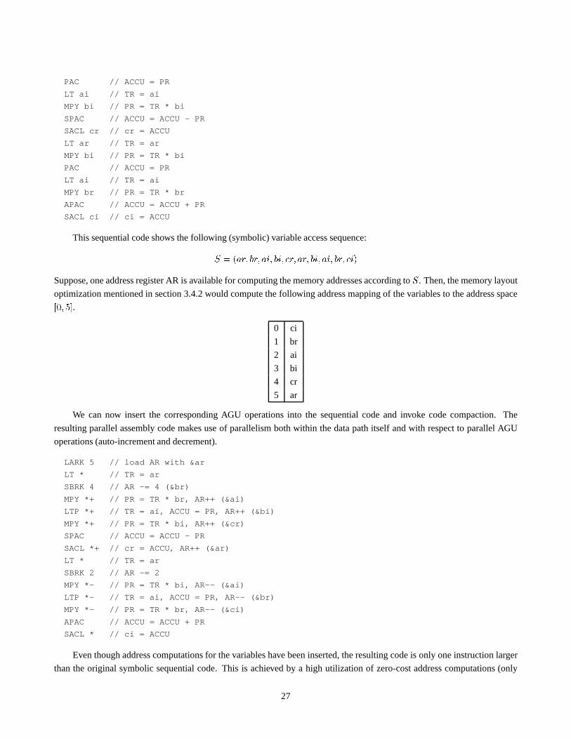
PAC // ACCU = PR
LT ai // TR = ai
MPY bi // PR = TR * bi
SPAC // ACCU = ACCU - PR
SACL cr // cr = ACCU
LT ar // TR = ar
MPY bi // PR = TR * bi
PAC // ACCU = PR
LT ai // TR = ai
MPY br // PR = TR * br
APAC // ACCU = ACCU + PR
SACL ci // ci = ACCU
This sequential code shows the following (symbolic) variable access sequence:S = (ar; br; ai; bi; cr; ar; bi; ai; br; ci)Suppose, one address register AR is available for computing the memory addresses according toS. Then, the memory layout
optimization mentioned in section 3.4.2 would compute the following address mapping of the variables to the address space[0; 5].0 ci
1 br
2 ai
3 bi
4 cr
5 ar
We can now insert the corresponding AGU operations into the sequential code and invoke code compaction. The
resulting parallel assembly code makes use of parallelism both within thedata path itself and with respect to parallel AGU
operations (auto-increment and decrement).
LARK 5 // load AR with &ar
LT * // TR = ar
SBRK 4 // AR -= 4 (&br)
MPY *+ // PR = TR * br, AR++ (&ai)
LTP *+ // TR = ai, ACCU = PR, AR++ (&bi)
MPY *+ // PR = TR * bi, AR++ (&cr)
SPAC // ACCU = ACCU - PR
SACL *+ // cr = ACCU, AR++ (&ar)
LT * // TR = ar
SBRK 2 // AR -= 2
MPY *- // PR = TR * bi, AR-- (&ai)
LTP *- // TR = ai, ACCU = PR, AR-- (&br)
MPY *- // PR = TR * br, AR-- (&ci)
APAC // ACCU = ACCU + PR
SACL * // ci = ACCU
Even though address computations for the variables have been inserted, the resulting code is only one instruction larger
than the original symbolic sequential code. This is achieved by a high utilization of zero-cost address computations (only
27

two extra SBRK instructions) as well as parallel LTP instructions, which perform two data moves in parallel. This would not
have been possible without memory layout optimization and code compaction.
3.6 Phase coupling
Even though code compaction is a powerful code optimization technique, only the direct coupling of sequential and parallel
code generation phases can yield globally optimal results. Phase-coupled techniques frequently have to resort to heuristics
due to extremely large search spaces. However, heuristics for phase-coupled code generation still may outperform exact
techniques solving only parts of the code generation problem. In this section we therefore summarize important approaches
to phase-coupled code generation for PDSPs.
Early work [77, 78] combined instruction scheduling with adata routingphase. In any step of scheduling, data routing
performs detailed register allocation based on resource availability in accordance with a partial schedule constructed so far.
In this way, the scheduling freedom (mobility) of instructions cannot be not obstructed by unfavorable register allocation
decisions made earlier during code generation. However, significant efforthas to be spent for avoidance ofscheduling
deadlocks, which restrict the applicability of such techniques to simple PDSP architectures.
Wilson’s approach to phase coupled code generation [79] is also based on Integer Linear Programming. In his formula-
tion, the complete search space, including register allocation, code selection, and code compaction is explored at once. While
this approach permits the generation of provable optimal code for basic blocks, the high problem complexity also imposes
heavy restrictions on applicability for realistic programs and PDSPs.
An alternative Integer Linear Programming formulation has been given in [80]. By better taking into account the detailed
processor architecture, optimal code could be generated for small size examplesfor the TI TMS320C25 DSP.
A more practical phase coupling technique is Mutation Scheduling [81]. During instruction scheduling, a set ofmuta-
tions is maintained for each program value. Each mutation represents an alternative implementation of value computation.
For instance, mutations for a common subexpression in a DFG may include storing the CSE in some special purpose register
or recomputing it multiple times. For other values, mutations are generated by application of algebraic rules like commuta-
tivity or associativity. In each scheduling step, the best mutation for eachvalue to be scheduled is chosen. While Mutation
Scheduling represents an ”ideal” approach to phase coupling, its efficacy critically depends on the scheduling algorithm used
as well as on the number of mutations considered for each value.
A constraint driven approach to phase-coupled code generation for PDSPs is presented in [82]. In that approach, alterna-
tives with respect to code selection, register allocation, and scheduling areretained as long as possible during code generation.
Restrictions imposed by the processor architecture are explicitly modeled in the form of constraints, which ensure correctness
of the generated code. The implementation makes use of aconstraint logic programmingenvironment. For several examples
it has been demonstrated that the quality of the generated code is equal to that of hand-written assembly code.
3.7 Retargetable compilation
As systems based on PDSPs mostly have to be very cost-efficient, a comparatively large number of different standard (”off-
the-shelf”) PDSPs are available on the semiconductor market at the same time. From this variety, a PDSP user may select
that processor architecture which matches his requirements at minimum costs.In spite of the large variety of standard DSPs,
however, it is still unlikely that a customer will find a processor ideally matching one given application. In particular, using
standard processors in the form of cores (layout macro cells) for systems-on-a-chip may lead to a waste of silicon area. For
mobile applications, also the electrical power consumed by a standard processor may be too high.
As a consequence, there is a trend towards the use of a new class of PDSPs, calledapplication specific signal processors
(ASSPs). The architecture of such ASSPs is still programmable, but iscustomized for restricted application areas. A well-
known example is the EPICS architecture [83]. A number of further ASSPs are mentioned in [52].
28

The increasing use of ASSPs for implementing embedded DSP systems leads to an even larger variety of PDSPs. While
the code optimization techniques mentioned in the previous sections help to improve the practical applicability of compilers
for DSP software development, they do not answer the question: Who will write compilers for all these different PDSP
architectures ? Developing a compiler for each new ASSP, possibly havinga low production volume and product lifetime, is
not economically feasible. Still, the use of compilers for ASSPs insteadof assembly programming is still highly desirable.
Therefore, researchers have looked at technology for developingretargetable compilers. Such compilers are not re-
stricted to generating code for a singletarget processor, but are sufficiently flexible to be reused for a whole class of PDSPs.
More specifically, we call a compiler retargetable, if adapting the compiler to anew target processor does not involve rewrit-
ing a large part of the compiler source code. This can be achieved by usingexternal processor models. While in a classical,
target-specific compiler the processor model is hard-coded in the compiler source code, a retargetable compiler can read an
external processor model as an additional input specified by the user and generate code for the target processor specified by
the model.
3.7.1 The RECORD compiler system
An example of a retargetable compiler for PDSPs is the RECORD system [84], a coarse overview of which is given in
fig. 25. In RECORD, processor models are given in the hardware description language (HDL) MIMOLA, which resembles
structural VHDL. A MIMOLA processor model captures the register transfer level structure of a PDSPs, including controller,
data path, and address generation units. Alternatively, the pure instruction set can be described, while hiding the internal
structure. Using HDL models is a natural way of describing processor hardware, with a large amount of modeling flexibility.
Furthermore, the use of HDL models reduces the number of different processor models required during the design process,
since HDL models can be used also for hardware synthesis and simulation.
Sequential code generation in RECORD is based on the data flow tree (DFT) model explained in section 3.3.1. The
source program, given in the programming language DFL, is first transformed into an intermediate representation, consisting
of DFTs. The code generator is automatically generated from the HDL processor model by means of the iburg tool [59].
Since iburg requires a tree grammar model of the target instruction set, some preprocessing of the HDL model is necessary.
RECORD uses aninstruction set extractionphase to transform the structural HDL model into an internal model of the
machine instruction set. This internal model captures the behavior of available machine instructions as well as the constraints
on instruction-level parallelism.
During sequential code generation, the code generator generated by means of iburg is used to map DFTs into target
specific machine code. While mapping, RECORD exploits algebraic rules like commutativity and associativity of operators to
increase code quality. The resulting sequential assembly code is further optimized by means of memory access optimization
(section 3.4) and code compaction (section 3.5). An experimental evaluation for the TI TMS320C25 DSP showed, that
thanks to these optimizations RECORD on the average generates significantly denser code than a commercial target specific
compiler, however at the expense of lower compilation speed. Furthermore, RECORD is easily retargetable to different
processor architectures. If a HDL model is available, then generation of processor specific compiler components typically
takes less than one workstation CPU minute. This short turnaround time permits to use a retargetable compiler also for
quickly exploring different architectural options for an ASSP, e.g., with respect to the number of functional units, register file
sizes, or interconnect structure.
3.7.2 Further retargetable compilers
A widespread example for a retargetable compiler is the GNU compiler ”gcc” [85]. Since gcc has been mainly designed for
CISC and RISC processor architectures, it is based on the assumption of regular processor architectures and thus is hardly
applicable to PDSPs.
29

The MSSQ compiler [86] has been an early approach to retargetable compilation based on HDL models, however without
specific optimizations for PDSPs.
In the CodeSyn compiler [57], specifically designed for ASSPs, the targetprocessor is heterogeneously described by the
set of available instruction patterns, a graph model representing the data path, and a resource classification that accounts for
special purpose registers.
The CHESS compiler [87] uses a specific language called nML for describing target processor architectures. It generates
code for a specific ASSP architectural style and therefore employs special codegeneration and optimization techniques [88].
The nML language has also been used in a retargetable compiler project at Cadence [89].
Several code optimizations mentioned in this paper [61, 62, 60, 63] have been implemented in the SPAM compiler at
Princeton University and MIT. Although SPAM can be classified as a retargetable compiler, it is more based on exchangeable
software modules performing specific optimization instead of an externaltarget processor model.
Another approach to retargetable code generation for PDSPs is the AVIV compiler [90], which uses a special language
(ISDL [91]) for modeling VLIW-like processor architectures.
As compilers for standard DSPs and ASSPs become more important and retargetable compiler technology gets more
mature, several companies have started to sell commercial retargetable compilerswith special emphasis on PDSPs. Examples
are the CoSy compiler development system by ACE, the commercial version of the CHESS compiler, as well as Archelon’s
retargetable compiler system. Detailed information about these recent software products is available on the World Wide Web
[92, 93, 94].
4 Conclusions
This paper has reviewed that state of the art in front- and back-end design automation technology for DSP software implemen-
tation. We have motivated a design flow that begins with a high-level, hierarchical block diagram specification; synthesizes
a C-language application program or subsystem from this specification; and then compiles the C program into optimized
machine code for the given target processor. We have reviewed several useful computational models that provide efficient
semantics for the block diagram specifications at the front end of this design flow, We then examined the vast space of im-
plementation trade-offs one encounters when synthesizing software fromthese computational models, in particular from the
closely-related synchronous dataflow (SDF) and scalable synchronous dataflow (SSDF) models, which can be viewed as key
“common denominators” of the other models. Subsequently, we examined avariety of useful software synthesis techniques
that address important subsets of and prioritizations of relevant optimization metrics.
Complementary to software synthesis issues, we have outlined the state-of-the-art in compilation of efficient machine
code from application source programs. Taking the step from assembly-level to C-level programming of DSPs demands
for special code generation techniques beyond the scope of classical compiler technology. In particular, this concerns code
generation, memory access optimization, and exploitation of instruction-level parallelism. Recently, also the problem of
tightly coupling these different compilation phases in order to generatedvery efficient code has gained significant research
interest. In addition, we have motivated the use of retargetable compilers, which are important for programming application-
specific DSPs.
In our overview, we have highlighted useful directions for furtherstudy. A particularly interesting and promising direc-
tion, which remains largely unexplored, is the investigation of the interaction between software synthesis and code generation
– that is, the development of synthesis techniques that explicitly aid the code generation process, and code generation tech-
niques that incorporate high-level application structure that is exposed during synthesis.
30

AGU
register fileaddress
(8 x 16)
data RAM(256 x 16)
ALU
ACCU
shifter
MUX
shifter
multiplier
TR
PR
(4096 x 16)program ROM
controller
exchangebus
ARP
program bus
data bus
16 16
16
16
32
32
3
16
Figure 1:Simplified architecture of Texas Instruments TMS320C25 DSP
31

Figure 2: The top-level block diagram specification of a discrete wavelet transform application implemented in Ptolemy [7].
32
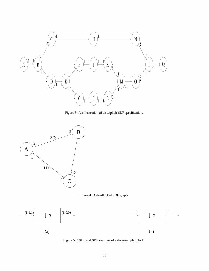
BA
C
D
J LG
I K
H N
P QF
ME O
111
1
1 1 1 1
1 1
1
1
1 1 1 1
1 1 1 1
2
2
2
2
2
2
2
1
11 2
1
1
1 1
1
Figure 3: An illustration of an explicit SDF specification.
B
A
C3
2
3
12
1D
3D
1
Figure 4: A deadlocked SDF graph.
(1,1,1) (1,0,0) 3 13
(a)
3
(b)
Figure 5: CSDF and SDF versions of a downsampler block.
33

K
+ Ψ
+
Ψ
IN xn
OUT ynG
111
1
1
1
1
1
1
1
1
(1,0)
(0,1)
(0,1)
(1,0)
A
C
E
B
D
F
= k²yn-1ny +kxn+xn-1= k(ky +x )+xn-1nn
CEG2FDBA1valid schedule: A
1D
1D
Figure 6: An example that illustrates the compact modeling of resource sharing using CSDF. The actor labeled denotes a
dataflowfork, which simply replicates its input tokens on all of its output edges. The lower portion of the figure gives a valid
schedule for this CSDF specification. Here,A1 andA2 denote the first and second phases of the CSDF actorA.
34

delay-free SDF cycle=> deadlock
K
+ INΨ
+
OUT
Ψ
111
1
1
1
1
1
1
1
1
1
1
1
1
1D
1D
Figure 7: The SDF version of the specification in fig. 6.
35

A B
D C D C
Ω’ Ω’schedule: CD
Ω’
Ω’
Ω
Ω’
D C
(a)
(c)
(b)
1 2
1D
1
2
: B
: A
1
1
(1,0)
11
1 1
1 11
111
1 1
11
1 1
(0,1)
Figure 8: An example that illustrates the utility of cyclo-static dataflow in constructing hierarchical specifications. Grouping
the actorsA andB into the hierarchical SDF actor, as shown in (b), results in a deadlocked SDF graph. In contrast, an
appropriate CSDF model of the hierarchical grouping, illustrated in (c), avoids deadlock. The two phases of the hierarchical
CSDF actor0 in (c) are specified in the lower right corner of the figure along with a valid schedule for the CSDF specification.
36

M1
M2
source distribute
source distribute
M1
M2
2N1
1 (N,N)
1
1
(b)
(a)
A
D
C1
1
N
N
B
(N,0)
(0,N)
Figure 9: An example of the use of CSDF to decrease buffering requirements.
37

OUT3 2(1,0)(1,1)(1,1,1)(1,0,0)
IN
A B C
FIR11 11
"deadsubgraphs"
IN A B C OUT
A B C
A B C OUT
IN A B C
A B C OUT
A B C
1 1 1 11
2 2 2
3 3 3
42
2
4 4
5
6
5 5
6 6
3
Figure 10: An example of efficient dead code elimination using CSDF.
imageexpander
(512x512) (1024x1024)
Figure 11: An example of an MDSDF actor.
X Y Z10 1 1
5D
1
Figure 12: A simple example that we use to illustrate trade-offs involved in compiling SDF specifications.
38
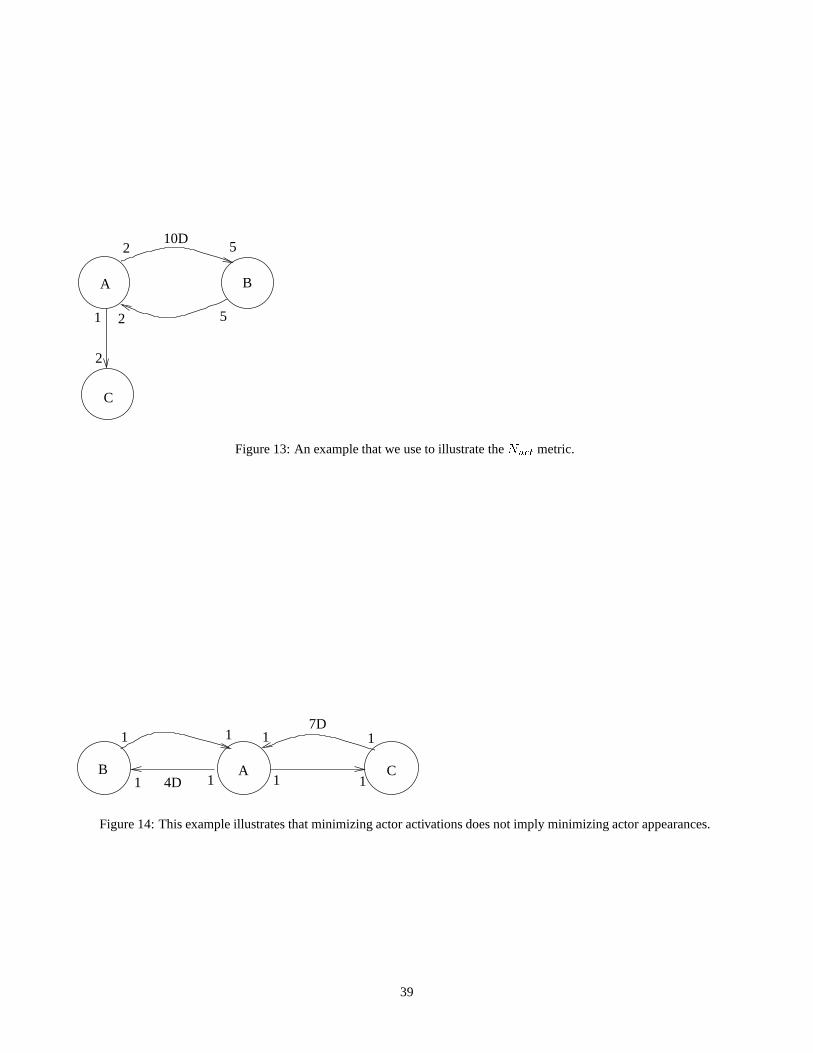
A B
C
2
1
2 5
52
10D
Figure 13: An example that we use to illustrate theNact metric.
111
B C4D
7D
1 1 1 1
1
A
Figure 14: This example illustrates that minimizing actor activationsdoes not imply minimizing actor appearances.
39

101
A B C D2 1 2 1 2 1
12242 1
12D 16D 12D
A Ω12 1
2 1
12D
B 2 1
24
16D
Ω2 C D2 1
12
12D
(b) (c) (d)
(a)
Figure 15: An illustration of a complete hierarchization.
40

source program
lexical analysissyntax analysis
semantical analysis
source code analyses
representation intermediate
machine-independentIR optimizations
representation intermediate
optimized
sequential code generation
code generation
memory access optimizationcode compaction
assembly program
Figure 16:Compilation phases
int a,b,c,d,x,y,z;
void f()
x = a + b;
y = a + b - c * d;
z = c * d;
Figure 17:Example C source code
41

load a load b load dload c
*
store x store y store z
+
-
Figure 18:DFG representation of code from fig. 17
load a load b load dload c
*
store x store y store z
+
- SUBMUL
LOAD LOAD
STORESTORESTORE
ADD
Figure 19:DFG from fig. 18 covered by instruction patterns
load a load b load dload c
*
store x store y store z
+
- SUB
LOAD LOAD
STORESTORESTORE
MAC
Figure 20:Using MAC for DFG covering
load a load b load dload c
*
store y store z
+
store x
write CSE write CSE
read CSE read CSE
read CSEread CSE
-
Figure 21:Decomposition of a DFG into DFTs
42

effectiveaddress
modify registerfile
addressregisterfile
+/-
"1"
AR pointer
AGU
immediate value
MR pointer
Figure 22:Address generation unit
LOAD AR, 1AR += 2AR -= 3AR += 2AR ++AR -= 3AR += 2AR --AR --AR += 3AR -= 3AR += 2AR ++
LOAD AR, 3AR --AR --AR --LOAD MR, 2AR += MRAR --AR --AR += 3AR -= MRAR ++AR --AR --AR += MR
bdacdacbadacd
LOAD AR, 3AR --AR --AR --AR += 2AR --AR --AR += 3AR -= 2AR ++AR --AR --AR += 2
bdacdacbadacd
bdac
acbadacd
dabcd
cadb
cadb
0123
0123
0123
a) b) c)
cost: 9 cost: 5 cost: 3
Figure 23:Alternative memory layouts and AGU operation sequences
a
c
b
d
4
3
2
1
1
1
a
c
b
d
4
3 1
access graph maximum weighted path
Figure 24:Access graph model and maximum weighted path
43

DFL source program
processor modelMIMOLA HDL
mapping to DFTsinstruction set
extraction
generation with iburgcode generator
sequential codegeneration
memory access optimizationcode compaction
assembly codesequential
parallel assembly code
Figure 25:Coarse architecture of the RECORD system
44
References
[1] The Design and Implementation of Signal Processing Systems Technical Committee. VLSI design and implementation
fuels the signal processing revolution.IEEE Signal Processing Magazine, 15(1):22–37, January 1998.
[2] P. Lapsley, J. Bier, A. Shoham, and E. A. Lee.DSP Processor Fundamentals. Berkeley Design Technology, Inc., 1994.
[3] E. A. Lee. Programmable DSP architectures — Part I.IEEE ASSP Magazine, 5(4), October 1988.
[4] E. A. Lee. Programmable DSP architectures — Part II.IEEE ASSP Magazine, 6(1), January 1988.
[5] P. Marwedel and G. Goossens, editors.Code Generation for Embedded Processors. Kluwer Academic Publishers,
1995.
[6] V. Zivojnovic, H. Schraut, M. Willems, and H. Meyr. DSPs, GPPs,and multimedia applications — an evaulation
using DSPstone. InProceedings of the International Conference on Signal Processing Applications and Technology,
November 1995.
[7] J. T. Buck, S. Ha, E. A. Lee, and D. G. Messerschmitt. Ptolemy: A framework for simulating and prototyping hetero-
geneous systems.International Journal of Computer Simulation, January 1994.
[8] P. P. Vaidyanathan.Multirate Systems and Filter Banks. Prentice Hall, 1993.
[9] E. A. Lee and D. G. Messerschmitt. Synchronous dataflow.Proceedings of the IEEE, 75(9):1235–1245, September
1987.
[10] E. A. Lee. Consistency in dataflow graphs.IEEE Transactions on Parallel and Distributed Systems, 2(2), April 1991.
[11] S. S. Bhattacharyya, P. K. Murthy, and E. A. Lee.Software Synthesis from Dataflow Graphs. Kluwer Academic
Publishers, 1996.
[12] S. Ritz, M. Willems, and H. Meyr. Scheduling for optimum data memory compaction in block diagram oriented software
synthesis. InProceedings of the International Conference on Acoustics, Speech, and Signal Processing, May 1995.
[13] E. A. Lee and D. G. Messerschmitt. Static scheduling of synchronous dataflow programs for digital signal processing.
IEEE Transactions on Computers, February 1987.
[14] E. A. Lee, W. H. Ho, E. Goei, J. Bier, and S. S. Bhattacharyya. Gabriel: Adesign environment for DSP.IEEE
Transactions on Acoustics, Speech, and Signal Processing, 37(11), November 1989.
[15] D. R. O’Hallaron. The ASSIGN parallel program generator. Technical report, School of Computer Science, Carnegie
Mellon University, May 1991.
[16] G. Bilsen, M. Engels, R. Lauwereins, and J. A. Peperstraete. Cyclo-static data flow. InProceedings of the International
Conference on Acoustics, Speech, and Signal Processing, pages 3255–3258, May 1995.
[17] G. Bilsen, M. Engels, R. Lauwereins, and J. A. Peperstraete. Cyclo-static dataflow. IEEE Transactions on Signal
Processing, 44(2):397–408, February 1996.
[18] G. De Micheli.Synthesis and Optimization of Digital Circuits. McGraw-Hill, 1994.
[19] T. M. Parks, J. L. Pino, and E. A. Lee. A comparison of synchronousand cyclo-static dataflow. InProceedings of the
IEEE Asilomar Conference on Signals, Systems, and Computers, November 1995.
45

[20] S. Ritz, M. Pankert, and H. Meyr. Optimum vectorization of scalable synchronous dataflow graphs. InProceedings of
the International Conference on Application Specific Array Processors, October 1993.
[21] S. Ritz, M. Pankert, and H. Meyr. High level software synthesis for signal processing systems. InProceedings of the
International Conference on Application Specific Array Processors, August 1992.
[22] E. A. Lee. Representing and exploiting data parallelism using multidimensional dataflow diagrams. InProceedings of
the International Conference on Acoustics, Speech, and Signal Processing, pages 453–456, April 1993.
[23] P. K. Murthy and E. A. Lee. An extension of multidimensional synchronous dataflow to handle arbitrary sampling
lattices. InProceedings of the International Conference on Acoustics, Speech, and Signal Processing, pages 3306–
3309, May 1996.
[24] G. R. Gao, R. Govindarajan, and P. Panangaden. Well-behaved programs for DSP computation. InProceedings of the
International Conference on Acoustics, Speech, and Signal Processing, March 1992.
[25] J. T. Buck and E. A. Lee. Scheduling dynamic dataflow graphs using thetoken flow model. InProceedings of the
International Conference on Acoustics, Speech, and Signal Processing, April 1993.
[26] J. T. Buck. Scheduling Dynamic Dataflow Graphs with Bounded Memory using theToken Flow Model. PhD thesis,
Department of Electrical Engineering and Computer Sciences, University of California at Berkeley, September 1993.
[27] J. T. Buck. Static scheduling and code generation from dynamic dataflow graphs with integer-valued control systems.
In Proceedings of the IEEE Asilomar Conference on Signals, Systems, andComputers, October 1994.
[28] S. S. Bhattacharyya, P. K. Murthy, and E. A. Lee. Optimal parenthesization of lexical orderings for DSP block diagrams.
In Proceedings of the International Workshop on VLSI Signal Processing. IEEE press, October 1995. Sakai, Osaka,
Japan.
[29] M. Ade, R. Lauwereins, and J. A. Peperstraete. Buffer memory requirements in DSP applications. InProceedings of
the IEEE Workshop on Rapid System Prototyping, pages 198–123, June 1994.
[30] M. Ade, R. Lauwereins, and J.A. Peperstraete. Data memory minimisation for synchronous data flow graphs emulated
on DSP-FPGA targets. InProceedings of the Design Automation Conference, pages 64–69, June 1994.
[31] M. Cubric and P. Panangaden. Minimal memory schedules for dataflow networks. InCONCUR ’93, August 1993.
[32] R. Govindarajan, G. R. Gao, and P. Desai. Minimizing memory requirements in rate-optimal schedules. InProceedings
of the International Conference on Application Specific Array Processors, August 1994.
[33] S. How. Code generation for multirate DSP systems in gabriel. Master’s thesis, Department of Electrical Engineering
and Computer Sciences, University of California at Berkeley, May 1990.
[34] S. S. Bhattacharyya, P. K. Murthy, and E. A. Lee. Synthesis of embeddedsoftware from synchronous dataflow specifi-
cations.Journal of VLSI Signal Processing Systems, 21(2):151–166, June 1999.
[35] S. S. Bhattacharyya, J. T. Buck, S. Ha, and E. A. Lee. A scheduling framework for minimizing memory requirements
of multirate DSP systems represented as dataflow graphs. InProceedings of the International Workshop on VLSI Signal
Processing, October 1993. Veldhoven, The Netherlands.
[36] S. S. Bhattacharyya, J. T. Buck, S. Ha, and E. A. Lee. Generating compact codefrom dataflow specifications of multirate
signal processing algorithms.IEEE Transactions on Circuits and Systems – I: Fundamental Theory and Applications,
42(3):138–150, March 1995.
46
[37] S. S. Bhattacharyya, P. K. Murthy, and E. A. Lee. APGAN and RPMC: Complementary heuristics for translating DSP
block diagrams into efficient software implementations.Journal of Design Automation for Embedded Systems, January
1997.
[38] P. K. Murthy, S. S. Bhattacharyya, and E. A. Lee. Joint minimizationof code and data for synchronous dataflow
programs.Journal of Formal Methods in System Design, 11(1):41–70, July 1997.
[39] J. L. Pino, S. S. Bhattacharyya, and E. A. Lee. A hierarchical multiprocessor scheduling system for DSP applications.
In Proceedings of the IEEE Asilomar Conference on Signals, Systems, andComputers, November 1995.
[40] P. K. Murthy and S. S. Bhattacharyya. Shared memory implementations of synchronous dataflow specifications using
lifetime analysis techniques. Technical Report UMIACS-TR-99-32, Institute for Advanced Computer Studies, Univer-
sity of Maryland at College Park, June 1999.
[41] P. K. Murthy and S. S. Bhattacharyya. A buffer merging technique forreducing memory requirements of synchronous
dataflow specifications. InProceedings of the International Symposium on Systems Synthesis, 1999. San Jose, Califor-
nia, to appear.
[42] E. Zitzler, J. Teich, and S. S. Bhattacharyya. Optimized software synthesis for DSP using randomization techniques.
Technical report, Computer Engineering and Communication Networks Laboratory, Swiss Federal Institute of Technol-
ogy, Zurich, July 1999. Revised version of teic1998x1.
[43] J. Teich, E. Zitzler, and S. S. Bhattacharyya. Optimized software synthesis for digital signal processing algorithms –
an evolutionary approach. InProceedings of the IEEE Workshop on Signal Processing Systems, October 1998. Boston,
Massachusetts.
[44] E. Zitzler, J. Teich, and S. S. Bhattacharyya. Evolutionary algorithms for the synthesis of embedded software.IEEE
Transactions on Very Large Scale Integration (VLSI) Systems, 1999. Accepted for publication; to appear.
[45] T. Back, U. Hammel, and H-P Schwefel. Evolutionary computation: Comments on the history and current state.IEEE
Transactions on Evolutionary Computation, 1(1):3–17, 1997.
[46] V. Zivojnovic, S. Ritz, and H. Meyr. Multirate retiming: A powerful tool for hardware/software codesign. Technical
report, Aachen University of Technology, 1993.
[47] V. Zivojnovic, S. Ritz, and H. Meyr. Retiming of DSP programs for optimum vectorization. InProceedings of the
International Conference on Acoustics, Speech, and Signal Processing, April 1994.
[48] W. Sung, J. Kim, and S. Ha. Memory efficient synthesis from dataflow graphs. InProceedings of the International
Symposium on Systems Synthesis, 1998.
[49] E. Zitzler, J. Teich, and S. S. Bhattacharyya. Multidimensional exploration of software implementations for DSP algo-
rithms. Journal of VLSI Signal Processing Systems, 1999. Accepted for publication; to appear.
[50] Mentor Graphics Corporation. DSP Architect DFL User’s and Reference Manual, V 8.26. 1993.
[51] M. Levy. C compilers for DSPs flex their muscles.EDN Access, issue 12, June 1997. http://www.ednmag.com
[52] P. Paulin, M. Cornero, C. Liem, et al. Trends in Embedded Systems Technology. In: M.G. Sami, G. De Micheli (eds.):
Hardware/Software Codesign, Kluwer Academic Publishers, 1996.
[53] K.M. Bischoff. Ox User’s Manual. Technical Report #92-31. Iowa State University, 1992.
47

[54] A.V. Aho, R. Sethi, J.D. Ullman.Compilers - Principles, Techniques, and Tools. Addison-Wesley, 1986.
[55] G.J. Chaitin. Register Allocation and Spilling via Graph Coloring. ACM SIGPLAN Symp. on Compiler Construction,
1982, pp. 98-105.
[56] A.V. Aho, M. Ganapathi, S.W.K Tjiang. Code Generation Using TreeMatching and Dynamic Programming.ACM
Trans. on Programming Languages and Systems, vol. 11, no. 4, 1989, pp. 491-516.
[57] C. Liem, T. May, P. Paulin. Instruction-Set Matching and Selection for DSP and ASIP Code Generation.European
Design and Test Conference (ED & TC), 1994, pp. 31-37.
[58] B. Wess. Automatic Instruction Code Generation based on Trellis Diagrams.IEEE Int. Symp. on Circuits and Systems
(ISCAS), 1992, pp. 645-648.
[59] C.W. Fraser, D.R. Hanson, T.A. Proebsting. Engineering a Simple, Efficient Code Generator Generator.ACM Letters
on Programming Languages and Systemsvol. 1, no. 3, 1992, pp. 213-226.
[60] G. Araujo, S. Malik. Optimal Code Generation for Embedded Memory Non-Homogeneous Register Architectures.8th
Int. Symp. on System Synthesis (ISSS), 1995, pp. 36-41.
[61] S. Liao, S. Devadas, K. Keutzer, S. Tjiang, A. Wang. Code Optimization Techniques for Embedded DSP Microproces-
sors.32nd Design Automation Conference (DAC), 1995, pp. 599-604.
[62] S. Liao, S. Devadas, K. Keutzer, S. Tjiang. Instruction Selection Using Binate Covering for Code Size Optimization.
Int. Conf. on Computer-Aided Design (ICCAD), 1995, pp. 393-399.
[63] G. Araujo, S. Malik, M. Lee. Using Register Transfer Paths in CodeGeneration for Heterogeneous Memory-Register
Architectures.33rd Design Automation Conference (DAC), 1996
[64] D.J. Kolson, A. Nicolau, N. Dutt, K. Kennedy. Optimal RegisterAssignment for Loops for Embedded Code Generation.
8th Int. Symp. on System Synthesis (ISSS), 1995.
[65] A. Sudarsanam, S. Malik. Memory Bank and Register Allocation in Software Synthesis for ASIPs.Int. Conf. on
Computer-Aided Design (ICCAD), 1995, pp. 388-392.
[66] D.H. Bartley. Optimizing Stack Frame Accesses for Processors with Restricted Addressing Modes.Software – Practice
and Experience, vol. 22(2), 1992, pp. 101-110.
[67] S. Liao, S. Devadas, K. Keutzer, S. Tjiang, A. Wang. Storage Assignment to Decrease Code Size.ACM SIGPLAN
Conference on Programming Language Design and Implementation (PLDI), 1995.
[68] R. Leupers, P. Marwedel. Algorithms for Address Assignment in DSP Code Generation.Int. Conf. on Computer-Aided
Design (ICCAD), 1996.
[69] B. Wess, M. Gotschlich. Optimal DSP Memory Layout Generation as a Quadratic Assignment Problem.Int. Symp. on
Circuits and Systems (ISCAS), 1997.
[70] A. Sudarsanam, S. Liao, S. Devadas. Analysis and Evaluation of Address Arithmetic Capabilities in Custom DSP
Architectures.Design Automation Conference (DAC), 1997.
[71] R. Leupers, F. David. A Uniform Optimization Technique for Offset Assignment Problems.11th Int. Symp. on System
Synthesis (ISSS), 1998.
48

[72] C. Liem, P.Paulin, A. Jerraya. Address Calculation for Retargetable Compilation and Exploration of Instruction-Set
Architectures.33rd Design Automation Conference (DAC), 1996.
[73] S. Davidson, D. Landskov, B.D. Shriver, P.W. Mallett. Some Experiments in Local Microcode Compaction for Hori-
zontal Machines.IEEE Trans. on Computers, vol. 30, no. 7, 1981, pp. 460-477.
[74] A. Timmer, M. Strik, J. van Meerbergen, J. Jess. Conflict Modellingand Instruction Scheduling in Code Generation for
In-House DSP Cores.32nd Design Automation Conference (DAC), 1995, pp. 593-598.
[75] R. Leupers, P. Marwedel. Time-Constrained Code Compaction for DSPs. IEEE Trans. on VLSI Systems, Vol. 5, No. 1,
1997.
[76] M. Berkelaar. Eindhoven University of Technology. available at ftp.es.ele.tue.nl/pub/lpsolve/
[77] K. Rimey, P.N. Hilfinger. Lazy Data Routing and Greedy Scheduling for Application-Specific Signal Processors.21st
Annual Workshop on Microprogramming and Microarchitecture (MICRO-21), 1988, pp. 111-115.
[78] R. Hartmann. Combined Scheduling and Data Routing for Programmable ASIC Systems.European Conference on
Design Automation (EDAC), 1992, pp. 486-490.
[79] T. Wilson, G. Grewal, B. Halley, D. Banerji. An Integrated Approach to Retargetable Code Generation.7th Int. Symp.
on High-Level Synthesis (HLSS), 1994, pp. 70-75.
[80] C.H. Gebotys. An Efficient Model for DSP Code Generation: Performance, Code Size, Estimated Energy.10th Int.
Symp. on System Synthesis (ISSS), 1997.
[81] S. Novack, A. Nicolau, N. Dutt. A Unified Code Generation Approach using Mutation Scheduling. Chapter 12 in [5].
[82] S. Bashford, R. Leupers. Constraint Driven Code Selection for Fixed-Point DSPs.36th Design Automation Conference
(DAC), 1999.
[83] R. Woudsma. EPICS: A Flexible Approach to Embedded DSP Cores.Int. Conf. on Signal Processing Applications and
Technology (ICSPAT), 1994.
[84] R. Leupers. Retargetable Code Generation for Digital Signal Processors. Kluwer Academic Publishers, ISBN 0-7923-
9958-7, 1997.
[85] R.M. Stallmann. Using and Porting GNU CC V2.4. Free Software Foundation, Cambridge/Massachusetts, 1993.
[86] L. Nowak. Graph based Retargetable Microcode Compilation in the MIMOLA Design System.20th Ann. Workshop on
Microprogramming (MICRO-20), 1987, pp. 126-132.
[87] D. Lanneer, J. Van Praet, A. Kifli, K. Schoofs, W. Geurts, F. Thoen, G. Goossens. CHESS: Retargetable Code Generation
for Embedded DSP Processors. chapter 5 in [5].
[88] J. Van Praet, D. Lanneer, G. Goossens, W. Geurts, H. De Man. A Graph Based Processor Model for Retargetable Code
Generation.European Design and Test Conference (ED & TC), 1996.
[89] M.R. Hartoog, J.A. Rowson, P.D. Reddy, et al. Generation of Software Tools from Processor Descriptions for Hard-
ware/Software Codesign.34th Design Automation Conference (DAC), 1997.
[90] S. Hanono, S. Devadas. Instruction Selection, Resource Allocation, and Scheduling in the AVIV retargetable code
generator.35th Design Automation Conference (DAC), 1998.
49

[91] G. Hadjiyiannis, S. Hanono, S. Devadas. ISDL: An Instruction-Set Description Language for Retargetability.34th
Design Automation Conference (DAC), 1997.
[92] ACE Associated Compiler Experts. http://www.ace.nl
[93] Target Compiler Technologies. http://www.retarget.com
[94] Archelon Inc. http://www.archelon.com
50

Biographical sketches of the authors
Shuvra S. Bhattacharyya
Shuvra S. Bhattacharyya received the Ph.D. degree in Electrical Engineeringand Computer Sciences from the University
of California at Berkeley in 1994. Since July, 1997, he has been an Assistant Professor in the Department of Electrical and
Computer Engineering at the University of Maryland at College Park. Heholds a joint appointment with the University of
Maryland Institute for Advanced Computer Studies (UMIACS).
Dr. Bhattacharyya’s research interests center around computer-aided design for embedded systems, with emphasis on
synthesis and optimization of hardware and software for digital signal/image/video processing (DSP) applications.
From 1991 to 1992, he was at Kuck and Associates, Inc. in Champaign, Illinois, where he was involved in the research
and development of program transformations for performance improvement in C and Fortran compilers. From 1994 to 1997,
he was a Researcher at the Semiconductor Research Laboratory of Hitachi America, Ltd., in San Jose, California. At Hitachi,
he was involved in research on software optimization techniques for embeddedDSP applications.
Dr. Bhattacharyya is a recipient of the NSF CAREER award (1997), and is co-author ofSoftware Synthesis from
Dataflow Graphs(Kluwer Academic Publishers, 1996), andEmbedded Multiprocessors: Scheduling and Synchronization
(Marcel-Dekker, to be published in 2000).
Rainer Leupers
Rainer Leupers received his Diploma and Ph.D. degrees in Computer Science with distinction from the University of
Dortmund, Germany, in 1992 and 1997, respectively. He received the Hans Uhde Award and the best dissertation award
from the University of Dortmund for outstanding theses. Since 1993, he has been working as a researcher at the Computer
Science Department at Dortmund, where he is currently heading the DSP compiler group. Dr. Leupers is the author of the
bookRetargetable Code Generation for Digital Signal Processors, published by Kluwer Academic publishers in 1997. His
research interests include design automation and compilers for embedded systems.
Peter Marwedel
Peter Marwedel received his Ph.D. in Physics from the University of Kiel (Germany) in 1974. He worked at the Com-
puter Science Department of that University from 1974 until 1989. In 1987, he received the Dr. habil. degree (a degree
required for becoming a professor) for his work on high-level synthesis and retargetable code generation based on the hard-
ware description language MIMOLA. Since 1989 he is a professor at the Computer Science Department of the University of
Dortmund (Germany). He served as the Dean of that Department between 1992 and 1995. Currently, he is the president of the
technology transfer institute ICD, located at Dortmund. His research areas include hardware/software codesign, high-level
test generation, high-level synthesis and code generation for embedded processors. He is one of the editors of the bookCode
Generation for Embedded Processorspublished by Kluwer Academic publishers in 1995. Dr. Marwedel is a memberof the
IEEE Computer society, the ACM, and the Gesellschaft fur Informatik (GI).
51