digital signal processing synthesis of human speech gavin … · 2008-12-11 · digital signal...
TRANSCRIPT
Digital Signal Processing
Synthesis of Human Speech
Gavin Cameron
MSc/PGD Electronics and Communication Engineering
January 31, 2000

Gavin Cameron, January 31, 2000 Page 2 of 26
TABLE OF CONTENTS LIST OF TABLES AND FIGURES . . . . . . . . . . . . . . . . . . . . . . . . . . . . . . . . . . . . . . . . . . . . . . . . . 3
ABSTRACT . . . . . . . . . . . . . . . . . . . . . . . . . . . . . . . . . . . . . . . . . . . . . . . . . . . . . . . . . . . . . . . . . . . . 4
INTRODUCTION . . . . . . . . . . . . . . . . . . . . . . . . . . . . . . . . . . . . . . . . . . . . . . . . . . . . . . . . . . . . . . . 5
HOW WE SPEAK . . . . . . . . . . . . . . . . . . . . . . . . . . . . . . . . . . . . . . . . . . . . . . . . . . . . . . . . . . . . . . . 6
HOW WE HEAR . . . . . . . . . . . . . . . . . . . . . . . . . . . . . . . . . . . . . . . . . . . . . . . . . . . . . . . . . . . . . . . . 8
TIME DOMAIN INTO FREQUENCY DOMAIN . . . . . . . . . . . . . . . . . . . . . . . . . . . . . . . . . . . . . 10
DESIGN OF CIRCUIT . . . . . . . . . . . . . . . . . . . . . . . . . . . . . . . . . . . . . . . . . . . . . . . . . . . . . . . . . . 12
PROGRAMMING THE ROM DEVICE . . . . . . . . . . . . . . . . . . . . . . . . . . . . . . . . . . . . . . . . . . . . . 15
ANALYSIS OF SPEECH . . . . . . . . . . . . . . . . . . . . . . . . . . . . . . . . . . . . . . . . . . . . . . . . . . . . . . . . 16
CONCLUSION . . . . . . . . . . . . . . . . . . . . . . . . . . . . . . . . . . . . . . . . . . . . . . . . . . . . . . . . . . . . . . . . 20
REFERENCES. . . . . . . . . . . . . . . . . . . . . . . . . . . . . . . . . . . . . . . . . . . . . . . . . . . . . . . . . . . . . . . . . 21
APPENDIX A - "srecord.c" . . . . . . . . . . . . . . . . . . . . . . . . . . . . . . . . . . . . . . . . . . . . . . . . . . . . . . . 22

Gavin Cameron, January 31, 2000 Page 3 of 26
LIST OF TABLES AND FIGURESFigure 1 - Anatomy of the vocal tract. . . . . . . . . . . . . . . . . . . . . . . . . . . . . . . . . . . . . . . . . . . . . . . . . 6
Figure 2 - Vocal comb . . . . . . . . . . . . . . . . . . . . . . . . . . . . . . . . . . . . . . . . . . . . . . . . . . . . . . . . . . . . 6
Figure 3 - Filtered vocal comb (phoneme) . . . . . . . . . . . . . . . . . . . . . . . . . . . . . . . . . . . . . . . . . . . . . 7
Figure 4 - The human ear . . . . . . . . . . . . . . . . . . . . . . . . . . . . . . . . . . . . . . . . . . . . . . . . . . . . . . . . . . 8
Figure 5 - The cochlea’s frequency response . . . . . . . . . . . . . . . . . . . . . . . . . . . . . . . . . . . . . . . . . . . 8
Figure 6 - Slicing the sample . . . . . . . . . . . . . . . . . . . . . . . . . . . . . . . . . . . . . . . . . . . . . . . . . . . . . . 10
Figure 7 - The Discrete Fourier Transform . . . . . . . . . . . . . . . . . . . . . . . . . . . . . . . . . . . . . . . . . . . 10
Figure 8 - Window Functions. . . . . . . . . . . . . . . . . . . . . . . . . . . . . . . . . . . . . . . . . . . . . . . . . . . . . . 11
Figure 9 - Block diagram of circuit . . . . . . . . . . . . . . . . . . . . . . . . . . . . . . . . . . . . . . . . . . . . . . . . . 12
Figure 10 - Circuit diagram . . . . . . . . . . . . . . . . . . . . . . . . . . . . . . . . . . . . . . . . . . . . . . . . . . . . . . . 13
Figure 11 - "Good Morning" . . . . . . . . . . . . . . . . . . . . . . . . . . . . . . . . . . . . . . . . . . . . . . . . . . . . . . 16
Figure 12 - ad 8 Point FFT, Rectangular, FS 64. . . . . . . . . . . . . . . . . . . . . . . . . . . . . . . . . . . . . . . . 17
Figure 13 - ad 8 Point FFT, Hamming, FS 64 . . . . . . . . . . . . . . . . . . . . . . . . . . . . . . . . . . . . . . . . . 17
Figure 14 - 2-D 8 Point FFT, Hamming, FS 64 . . . . . . . . . . . . . . . . . . . . . . . . . . . . . . . . . . . . . . . . 18
Figure 15 - ad 10 point FFT, Hamming, FS 64 . . . . . . . . . . . . . . . . . . . . . . . . . . . . . . . . . . . . . . . . 18
Figure 16 - 2-D 10 point FFT, Hamming, FS 64 . . . . . . . . . . . . . . . . . . . . . . . . . . . . . . . . . . . . . . . 19
Figure 17 - Students larynx comb. . . . . . . . . . . . . . . . . . . . . . . . . . . . . . . . . . . . . . . . . . . . . . . . . . . 19

Gavin Cameron, January 31, 2000 Page 4 of 26
ABSTRACTThis report contains an investigation into speech synthesis and the design of an electronic system to replay 1 second of speech.
It briefly covers the mechanics of the human speaking and listening systems and also covers Fourier analysis techniques.
The report then focuses on the design of the system, which was not actually constructed due to limitations in the requirement of the laboratory exercise.
Finally the students own voice is analyzed saying the words "Good Morning" with a view to investigating the frequency components that make up the students voice.

Gavin Cameron, January 31, 2000 Page 5 of 26
INTRODUCTIONWe live out our lives in a linear time world. However, time domain, in many cases, is not the most efficient domain for working in.
It has only been in the past couple of centuries that we have discovered the frequency domain and how to manipulate information between domains.
Speech is a prime example of this. Nature has found the most efficient way to communicate to be the frequency domain. We talk in harmonics. We hear frequencies. We process these frequencies in parallel. There is also redundancy in speech frequency content to make error detection and correction possible, i.e. in a noisy environment, speech can still be recognized by the brain.

Gavin Cameron, January 31, 2000 Page 6 of 26
HOW WE SPEAKThe production of speech by the human body involves three primary elements:
1. Lungs - these produce a stream of air as the "fuel" for the sound.
2. Larynx - air passing through the larynx is excited by the fundamental frequency of the larynx, and all the harmonics of it.
3. Vocal tract (which includes the mouth and nasal cavity) - these elements filter the broad band sound from the larynx, allowing different frequencies through for the different phonemes of human speech. Figure 1 shows a diagram of the various elements.
Figure 1 - Anatomy of the vocal tract
The broad band spectrum produced by the larynx, referred to as a "comb" is shown in figure 2:
Figure 2 - Vocal comb
Frequency
Power

Gavin Cameron, January 31, 2000 Page 7 of 26
As this sound passes through the vocal tract, it may be filtered to form a spectral response like the one shown in figure 3, for example:
Figure 3 - Filtered vocal comb (phoneme)
Frequency
Power
Human speech is made up of one such phoneme approximately every 200ms. When combined together, they form spoken words.
Electronic speech synthesizer ICs (for example, General Instruments SP0256A-AL2) use this technique to reproduce speech. This device has 58 different phonemes for constructing words as well as 5 defined delays for pauses between words.
Some speach recognition systems look for spectral peaks in the phonemes to determine what is being said. These form a signature of a persons voice.

Gavin Cameron, January 31, 2000 Page 8 of 26
HOW WE HEARSound enters the ear through the external canal and "hits" the ear drum at the end of the canal. Connected to the ear drum are three small bones (The Hammer, Stirrup and Anvil) which connect to the cochlea. The opening at the start of the cochlea is smaller than the ear drum, causing the sound to be amplified as the vibrations from the large drum are transmitted through the bones and onto the small surface of the cochlea. These components are shown below in figure 4.
Figure 4 - The human ear
Sound travels down the cochlea from the base to the apex. The hairs on the basilar membrane become longer as they near the apex. These hairs vibrate at lower resonant frequencies than the hairs at the base as shown in figure 5.
Figure 5 - The cochlea’s frequency response

Gavin Cameron, January 31, 2000 Page 9 of 26
Information from the whole length of the basilar membrane is taken as electrical signals to the brain in parallel, hence the brain actually receives a spectrum of sound directly. Waveform content is lost as it is not required.
The brain, through growing up, learns to recognize each of the phonemes used in speech and when receiving a string of them can build up words and phrases.
There is a lot of frequency content in the phoneme, some of which is not required. This is natures way of building in, what is nowadays known as error detection and correction. This is normally associated with digital communications, but is equally applicable to nature. This redundancy in the phoneme allows for reception of the phonemes in a noisy environment. Also, in telecommunications equipment, allows a greatly reduced bandwidth to be passed which can still be understood by the listener (approximately 100-12kHz down to 300-3.4kHz).
The brain can only perceive changes in frequency content approximately every 25th of a second (the sampling rate of the auditory cortex). It is sensitive to changes in frequency of about 1.5% which equates to about 1/4 of a semi-tone. It can perceive changes in volume of about 2dB.

Gavin Cameron, January 31, 2000 Page 10 of 26
TIME DOMAIN INTO FREQUENCY DOMAINConversion of data from the time domain into the frequency domain is normally performed using Fourier transformations.
The speech is sampled at regular intervals (sampling frequency) and is quantized into a number of levels. In order for a Fourier transformation to work, the digitized sample is cut into slices and is assumed to be repetitive. This is illustrated in Figure 6:
Figure 6 - Slicing the sample
Slice
........
time
time
T
TThe minimum frequency that can be extracted from this waveform is 1/T with all other frequency components being harmonics of 1/T. A Fourier transform is then performed on the slice using the Discrete Fourier Transform as defined in figure 7:
Figure 7 - The Discrete Fourier Transform
G(jω)k = ∑N −1
xn exp( )− j2πkn
N
n = 0
Where:
N = Number of samples in slice
k = the order of harmonic being examined
From figure 6, it can be observed that when the slice is folded around on itself, there is a step between the end of one cycle and the start of the next cycle. This effectively causes "noise" in the

Gavin Cameron, January 31, 2000 Page 11 of 26
output spectrum. It is caused by the very high frequency component which results from the step. The effects of the step can be minimized by applying a window function to the slice to reduce the amplitude of the signal at both ends of the slice. Typical windows are illustrated in figure 8:
Figure 8 - Window Functions
1
0
Rectangular
1
0
Hanning
1
0
Hamming
The rectangular window is one where the slice is unmodified (as described earlier). The following equations of the window functions would be applied to the slice:
Rectangular
ω = 1
Hanning
ω = 0.5 + 0.5cos( )2πn
N
Hamming
ω = 0.54 + 0.46cos( )2πn
N
These functions slightly distort the real magnitude of frequency content, however, they give a more accurate representation of which frequencies are present.
The lowest frequency measurable and resolution of the FFT are limited by the framesize. The highest frequency measurable is limited to the Nyquist frequency (half of the sampling frequency).

Gavin Cameron, January 31, 2000 Page 12 of 26
DESIGN OF CIRCUITThe circuit for replaying of speech was designed using time domain techniques only, i.e. the voice would be sampled at equal time intervals and digitized. When played back, these samples would re-create the original recording.
The sampling speed of the signal must be high enough to encompass the vocal spectrum. Most digital telephone systems digitize the speech at 8kHz which gives a bandwidth of 4kHz (Nyquist’s theorem) which is adequate for reasonable quality reproduction.
Speech can be adequately quantized at 256 levels, i.e. 8 bits, unlike high quality digital music which is quantized at a minimum of 16 bits.
To record 1 second of speech, 1 byte wide, at 8kHz requires a memory device of 8192 bytes (8kbytes) to store the information, ie 2^13.
A counter would be used, clocked at 8kHz, to provide an address sequence to the memory. The output of the memory would be clocked into a digital to analogue convertor (DAC). The output of the DAC would be filtered before amplification. This filtering removes the high frequency components caused by the DAC output switching between quantization levels. A block diagram of the system is shown below in figure 9:
Figure 9 - Block diagram of circuit
Counter Memory DAC Filter
Clock
Amp.
Suitable components were investigated. These were:
NE555 - Timer module to produce 8kHz clock.
MC14490 - Bounce eliminator to de-bounce the "start" switch.
PAL22V10 - Programmable logic device to provide the count and simple logic.
M28C64C - 64 kbit EEPROM to hold the speech sample.
TLV5619 - Parallel DAC.
MAX291 - 8th order Butterworth low pass filter.
The circuit diagram is shown below in figure 10:

Gavin Cameron, January 31, 2000 Page 13 of 26
Figure 10 - Circuit diagram
SW1
U1
U2
U3
U4
U5 U6 U7
14 2
7 9
C1
1
1
Clk8
Start
End
Enable CarryOut
EnableIn
Q13
Q5:Q0
Q11:Q6
CarryIn
AddrData DIn AOut In
Ena
ble
Ena
ble
Wri
te
LD
AC
3
Amp.
5
7
62
R1
R2
C2C3
Out
Circuit Description
Designation Device FunctionU1 Motorola
MC14490Debounces the switch input signal. C1 (27nF) provides an internal clock for the state machine. The output changes after the input has settled.
U2 SGS ThomsonNE555
This provides the 8kHz clock. The external components R1 (47k), R2 (3.9k) and C2 (3.3nF) control the frequency. C3 (10nF) provides a control voltage to the device, as this device can be configured in many ways to provide different functions. The variable resistor is to adjust the frequency to exactly 8kHz.
U3 AtmelATF22V10C
This programmable device contains an SR flip flop with the "Start" input to activate and the "End" to de-activate. The output of this, "Enable," is used to enable the internal synchronous counter and reset it when finished. The "CarryOut" is passed onto the next stage of the counter.
U4 AtmelATF22V10C
This programmable device contains the upper 6 bits of the count sequence. It provides the "End" signal which is actually the next bit in the count sequence.
U5 SGS ThomsonM28C64C
64kbit (8k x 8) EEPROM containing the digitized speech sample

Gavin Cameron, January 31, 2000 Page 14 of 26
U6 Texas InstrumentsTLV5619
The digital to analogue convertor (DAC). Data is registered into the device on the rising edge of Write and then internally transferred to the resistor network DAC.
U7 MaximMAX291
8th order Butterworth low pass filter to remove the high frequency components from the DAC output to leave the audio frequencies.
The circuit was not build as this was not a requirement of the laboratory exercise. If it had, then the programmable logic devices would also have to be designed. Such a tool for doing this is called Abel. A logic program is written using the Abel language, a line of the program may look like:
Count := (Count + Enable);
This is how the counter would be defined. Abel is aware of the building blocks required to synthesize a counter, so a large set of logic equations can effectively be written in one line. In this case the counter would only increment if the Enable signal is a logic "1."
Abel also has the facility to "virtually" test the program by means of test vectors. These would be written at the end of the program and would be a tabulated set of inputs and expected outputs. During the compilation and synthesizing process, the test vectors would be fed into a virtual device and its outputs at any given state be compared to that in the expected results table. This can greatly reduce de-bugging a design - the board does not have to be constructed to simulate the discrete functions.

Gavin Cameron, January 31, 2000 Page 15 of 26
PROGRAMMING THE ROM DEVICEPROM devices generally require special hardware to "blow" a program into them. A Typical programmer is a DataIO which can be connected up to any PC. The programmer requires 2 files in order to program a device. Firstly a configuration file for the specific device. This tells the programmer how many pins the device has, which pin is which, programming voltages etc. and are available from component vendors and programming hardware vendors. The other file is the actual program. These are always specially structured files, usually using ASCII characters. A typical file format for PROMs is the Motorola S-Record format.
An individual S-Record consists of a record type, a word count, an address, data and a checksum. A typical S-Record may look like:
S107003000144ED492
Which translates as:
S1 - The address field is 2 bytes and the data field is address loadable data.
07 - 7 bytes remaining in the record (one byte is represented as 2 ASCII characters)
0030 - Starting address of loadable data
00 14 4E D4 - Data
92 - Checksum of record
Using the "C" programming language, a program was created to convert a binary file into an S-Record file for use with a PROM programmer. See Appendix A for the program
The sample "Good Morning" would be digitized onto a PC. The file would be saved as a raw bye stream of the sample (WAV files and others, have extra information in them which is of no use to this task). The sample file would be passed onto the "srecord" program which would produce an S-Record file ready to blow into a PROM.

Gavin Cameron, January 31, 2000 Page 16 of 26
ANALYSIS OF SPEECHUsing Hypersignal on a PC, the sample "Good Morning" was digitized. The resulting time domain waveform is shown below in figure 11:
Figure 11 - "Good Morning"
G
oo
d
M
o
nng
r
i
The various phonemes that make up the phrase "Good Morning" have been indicated on the diagram. From this trace, only volume of the speech can be observed, i.e. which parts of the phrase were spoken softly and which loudly. The signature of the phonemes cannot be determined as no frequency information can be visibly obtained.
However, if the sample is analyzed using Fourier transformation techniques, information about the frequency content of the sample can be observed.
Shown in figure 12 is an 8 point FFT of the sample, with a 64 element frame size, using a rectangular window to "slice" the sample.

Gavin Cameron, January 31, 2000 Page 17 of 26
Figure 12 - ad 8 Point FFT, Rectangular, FS 64
This method of slicing the sample gives a false impression of the frequency content due to the fact that when the slice is folded around onto itself (to create an infinitely cyclic waveform) there is a step in the slice at the transition between the end and start of the slice.
In order to eliminate this step, a filter window can be applied to the slice before the FFT is performed on it. One such window is a Hamming Window. Figure 13 shows the same FFT, but with a Hamming window:
Figure 13 - ad 8 Point FFT, Hamming, FS 64
The analysis can also be shown 2-dimensionally, with the magnitude shown graded into a band of colours or shades of grey as shown in figure 14:

Gavin Cameron, January 31, 2000 Page 18 of 26
Figure 14 - 2-D 8 Point FFT, Hamming, FS 64
From these spectograms, it can be seen that virtually all of the frequency content is low down indicating large larynx to produce the low excitation frequency of around 200Hz.
During the time of the "oo" of "Good" it can be seen that there are high frequency harmonics around the 2kHz and 3kHz. These are caused by the back of the throat (2kHz) and nasal cavity (3kHz). In the 3D analysis, harmonics can be observed in the "o" of "Morning" these are lower than the previous harmonics, but from all of these, the comb of the wideband sound from the larynx can be approximated. Since the horizontal scale is linear, it is easy to measure with a ruler. Doing this, the harmonics are approximately 240Hz apart.
However, this analysis was performed with 8 point FFT. If this is increased to a 10 point FFT, much more frequency information can be obtained. Shown in figures 15 and 16 are the corresponding plots with 10 point FFTs:
Figure 15 - ad 10 point FFT, Hamming, FS 64

Gavin Cameron, January 31, 2000 Page 19 of 26
Figure 16 - 2-D 10 point FFT, Hamming, FS 64
Measuring the distance between peeks with this resolution, the harmonics are approximately 170 Hz apart. Therefor, the comb of the students larynx output may look as shown in figure 17:
Figure 17 - Students larynx comb
Frequency
Power
170
340
510
680
850
1020
1190
1360
2530
......
Since the fundamental frequency depends on the elasticity of the larynx, it (and all the harmonics) can vary depending how stressed or relaxed the subject is.
Greater frequency resolution could be obtained by "padding" the frame with extra "0"s, ie. a 64 sample frame size gives 64 freequency components, padding an extra 36 "0"s would give a frame size of 100 and 100 frequencies.
Gavin Cameron, January 31, 2000 Page 20 of 26
CONCLUSIONSince starting this exercise, the student has become more aware of how the harmonic content of voices are formed and why voices sound different over the telephone (limited bandwidth) or when people catch the cold or flu (as the nasal cavity becomes blocked, certain harmonics are prevented from being heard).
The student has gained some understanding into the phonemes that make up speech and now realizes how the speech synthesizer built as an electronics kit many years ago produces its speech.
The design of the electronic circuit was based on simple techniques of sampling and replaying. If the student had the understanding of speech before the project, perhaps the design might have been completely different. For example, it may have been in the form of a vocoder where all the phonemes would be analyzed to find their spectral content, with magnitudes measured. An electronic wide band sound would be produced to replicate the spectral comb of the students own voice. Each frequency produced would have a variable amplifier controlled by a set of programmable registers to give the same magnitude as the recorded spectrum. All the frequencies would be combined together and the resulting sound out would closely resemble the original phoneme recorded. The amplifier co-efficients would then be changed for the next phoneme. By simply varying the fundamental frequency the whole pitch of the voice could be changed which is a very complex task in the time domain. This would be a far more complex design than present, but would have been very rewarding if successfully implemented.

Gavin Cameron, January 31, 2000 Page 21 of 26
REFERENCESMotorola S-Record description:
http://www.cc.ndsu.nodak.edu/instruct/tareski/373f98/notes/srecord.htm
Anatomy of the vocal tract (figure 1):
http://www.umanitoba.ca/faculties/arts/linguistics/russell/138/sec1/anatomy.htm
Speech production and perception (figure 4):
http://ee.mokwon.ac.kr/~music/tutorials/speech2/speech.html
Encyclopedia Britanica (figure 5):
http://www.eb.com:180/bol/topic?asmbly_id=1693
Datasheet - Motorola, MC14490
http://scgproducts.motorola.com/Collateral/DataSheet/mc14490rev3.pdf
Datasheet - SGS Thomson, NE555
http://eu.st.com/stonline/books/pdf/docs/2182.pdf
Datasheet - Atmel, ATF22V10C
http://www.atmel.com/atmel/acrobat/doc0735.pdf
Datasheet - SGS Thomson, M28C64C
http://eu.st.com/stonline/books/pdf/docs/2550.pdf
Datasheet - Texas Instruments, TLV5619
http://www-s.ti.com/sc/psheets/slas172b/slas172b.pdf
Datasheet - Maxim, MAX291
http://209.1.238.250/arpdf/1370.pdf

Gavin Cameron, January 31, 2000 Page 22 of 26
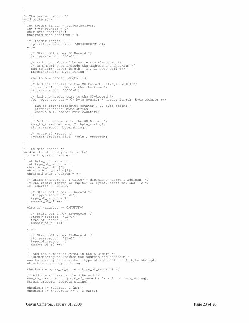
APPENDIX A - "srecord.c"/* srecord.c
This program converts a binary file (any format) into a Motorola S-Record file for blowing into a PROM.
Depending on the address, S1, S2 or S3 records shall be used as follows: up to record address 0xFFF0, S1 - 2 byte address up to record address 0xFFFFF0, S2 - 3 byte address up to record address 0xFFFFFFF0, S3 - 4 byte address
It takes each byte in the file, coverts it into an ASCII representation of the Hexadecimal value and constructs S-Records of up to 16 data bytes.
Up to 100 S1/2/3 records shall be written and then an S5 to break up the block of data.
An S9, S8 or S7 record shall then be written to terminate the file. Type determined by the execution start address given.
Gavin Cameron 04/11/1999*/
#include <stdio.h>#include <string.h>#include <stdlib.h>
/* Global variables */char source_name[FILENAME_MAX];char srecord_name[FILENAME_MAX];char srecord[47];char header[60];
unsigned char buffer[16];unsigned long number_of_s1 = 0;unsigned long number_of_s2 = 0;unsigned long number_of_s3 = 0;unsigned long number_of_s_in_segment = 0; /* No more that 100 records before an S5 */unsigned long address = 0;unsigned long execute = 0;
FILE *source_file;FILE *srecord_file;
void usage(){ printf("\nusage: srecord source [-o object] [-a address] [-e execute] [-h header]\n"); printf(" or\n"); printf(" srecord --help\n\n");}
void help(){ printf("This program produces a Motorola S-Record file from a binary file.\n\n"); printf(" --help: displays this help message\n"); printf(" source: may be any source file\n"); printf(" -o object: the S-Record file [default out.s]\n"); printf("-a address: the address (in HEX) of the start of the data [default 0x0000]\n"); printf("-e execute: the address (in HEX) of the start of execution [default 0x0000]\n"); printf(" -h header: up to 60 characters of text information [default \"\"]\n\n");}
void num_to_str (numeric, width, string) unsigned long numeric; unsigned long width; /* number of nibbles */ char *string;{ unsigned short nibble; short index; /* Split the 8 / 16 / 24 / 32 bit number into 2 / 4 / 6 / 8 4 bit quantities... */ for (index = 0; index < width; index++) { /* ... and shift each in turn down to the least significant 4 places */ nibble = (numeric & (0xf << (index * 4))) >> (index * 4); if (nibble <= 9)
/* 48 is ASCII code for character ’0’ */*(string + (width - 1 - index)) = nibble + 48;
else/* 65 is ASCII code for character ’A’, but this represents a value *//* of 10 so we just need to add 55 to get ASCII representation. */*(string + (width - 1 - index)) = nibble + 55;
} /* Terminate the string */ *(string + width) = ’\0’;
Gavin Cameron, January 31, 2000 Page 23 of 26
}
/* The header record */void write_s0(){ int header_length = strlen(header); int byte_counter = 0; char byte_string[3]; unsigned char checksum = 0;
if (header_length == 0) fprintf(srecord_file, "S0030000FC\n"); else { /* Start off a new S0-Record */ strcpy(srecord, "S0\0");
/* Add the number of bytes in the S0-Record */ /* Remembering to include the address and checksum */ num_to_str((header_length + 3), 2, byte_string); strcat(srecord, byte_string); checksum = header_length + 3;
/* Add the address to the S0-Record - always 0x0000 */ /* so nothing to add to the checksum */ strcat(srecord, "0000\0");
/* Add the header text to the S0-Record */ for (byte_counter = 0; byte_counter < header_length; byte_counter ++) { num_to_str(header[byte_counter], 2, byte_string); strcat(srecord, byte_string); checksum += header[byte_counter]; }
/* Add the checksum to the S0-Record */ num_to_str(~checksum, 2, byte_string); strcat(srecord, byte_string); /* Write S0 Record */ fprintf(srecord_file, "%s\n", srecord); }}
/* The data record */void write_s1_2_3(bytes_to_write) size_t bytes_to_write;{ int byte_counter = 0; int type_of_record = 0; char byte_string[3]; char address_string[9]; unsigned char checksum = 0;
/* Which S-Record do I write? - depends on current address! */ /* The record length is (up to) 16 bytes, hence the LSB = 0 */ if (address <= 0xFFF0) { /* Start off a new S1-Record */ strcpy(srecord, "S1\0"); type_of_record = 1; number_of_s1 ++; } else if (address <= 0xFFFFF0) { /* Start off a new S2-Record */ strcpy(srecord, "S2\0"); type_of_record = 2; number_of_s2 ++; } else { /* Start off a new S3-Record */ strcpy(srecord, "S3\0"); type_of_record = 3; number_of_s3 ++; }
/* Add the number of bytes in the S-Record */ /* Remembering to include the address and checksum */ num_to_str((bytes_to_write + type_of_record + 2), 2, byte_string); strcat(srecord, byte_string);
checksum = bytes_to_write + type_of_record + 2;
/* Add the address to the S-Record */ num_to_str(address, (type_of_record * 2) + 2, address_string); strcat(srecord, address_string);
checksum += (address & 0xFF); checksum += ((address >> 8) & 0xFF);

Gavin Cameron, January 31, 2000 Page 24 of 26
if (type_of_record != 1) checksum += ((address >> 16) & 0xFF); if (type_of_record == 3) checksum += ((address >> 24) & 0xFF);
/* Add (up to) 16 bytes of data to the S-Record */ for (byte_counter = 0; byte_counter < bytes_to_write; byte_counter ++) { num_to_str(buffer[byte_counter], 2, byte_string); strcat(srecord, byte_string); checksum += buffer[byte_counter]; }
/* Add the checksum to the S-Record */ num_to_str(~checksum, 2, byte_string); strcat(srecord, byte_string); /* Write S Record */ fprintf(srecord_file, "%s\n", srecord);}
/* The count record */void write_s5(number_of_s) unsigned int number_of_s;{ char byte_string[3]; char address_string[5]; unsigned char checksum = 0;
/* Start off a new S5-Record, with count = 3 */ strcpy(srecord, "S503\0"); checksum = 3;
/* Add the number of S records - in the address field */ num_to_str(number_of_s, 4, address_string); strcat(srecord, address_string);
checksum += (number_of_s & 0xFF); checksum += ((number_of_s >> 8) & 0xFF);
/* Add the checksum to the S5-Record */ num_to_str(~checksum, 2, byte_string); strcat(srecord, byte_string);
/* Write S5 Record */ fprintf(srecord_file, "%s\n", srecord);}
/* The termination record */void write_s9_7_6(){ int execute_length = 0; char byte_string[3]; char address_string[9]; unsigned char checksum = 0;
/* Which S-Record do I write? - depends on execution address! */ if (execute <= 0xFFFF) { /* Start off a new S9-Record */ strcpy(srecord, "S903\0"); execute_length = 2; checksum = 3; } else if (execute <= 0xFFFFFF) { /* Start off a new S8-Record */ strcpy(srecord, "S804\0"); execute_length = 3; checksum = 4; } else { /* Start off a new S7-Record */ strcpy(srecord, "S705\0"); execute_length = 4; checksum = 5; }
/* Write execution start address */ num_to_str(execute, execute_length * 2, address_string); strcat(srecord, address_string);
checksum += (execute & 0xFF); checksum += ((execute >> 8) & 0xFF); if (execute_length != 2) checksum += ((execute >> 16) & 0xFF); if (execute_length == 4) checksum += ((execute >> 24) & 0xFF);
/* Add the checksum to the S-Record */ num_to_str(~checksum, 2, byte_string);

Gavin Cameron, January 31, 2000 Page 25 of 26
strcat(srecord, byte_string);
/* Write S Record */ fprintf(srecord_file, "%s\n", srecord);}
void create_Srecords(){ size_t bytes_read = 0;
write_s0();
while ((bytes_read = fread(buffer, sizeof(char), 16, source_file)) != 0) { write_s1_2_3(bytes_read); address += 16; number_of_s_in_segment ++;
/* 100 S? Record written since a break, so take one */ if (number_of_s_in_segment == 100) { write_s5(number_of_s_in_segment); number_of_s_in_segment = 0; } } if (number_of_s_in_segment != 0) write_s5(number_of_s_in_segment);
write_s9_7_6();
printf("srecord: Created %d S1 records.\n", number_of_s1); printf(" %d S2 records.\n", number_of_s2); printf(" %d S3 records.\n\n", number_of_s3);}
main(argc, argv) int argc; char *argv[];{ int counter = 1; int rtn = 0;
/* Wrong number of arguments */ if (argc == 1) { usage(); exit(1); }
/* Set up default values */ strcpy(srecord_name, "out.s\0"); address = 0; strcpy(header, "\0");
/* Strip out information from command line */ while(counter < argc) { /* Help Required */ if (strcmp(argv[counter], "--help") == 0) { usage(); help(); exit(1); }
/* Object file */ if (strcmp(argv[counter], "-o") == 0) { if ((counter + 1) < argc) {
strcpy(srecord_name, argv[counter + 1]);counter ++;
} }
/* Start address of S-Records */ else if (strcmp(argv[counter], "-a") == 0) { if ((counter + 1) < argc) {
rtn = sscanf(argv[counter + 1], "%X", &address);if ((rtn == 0) || (rtn == EOF)){ usage(); printf("srecord: Invalid start address\n\n"); exit(1);}else counter ++;
} }

Gavin Cameron, January 31, 2000 Page 26 of 26
/* Execution start address */ else if (strcmp(argv[counter], "-e") == 0) { if ((counter + 1) < argc) { rtn = sscanf(argv[counter + 1], "%X", &execute);
if ((rtn == 0) || (rtn == EOF)){ usage(); printf("srecord: Invalid execution start address\n\n"); exit(1);}else counter ++;
} }
/* Header Information */ else if (strcmp(argv[counter], "-h") == 0) { if ((counter + 1) < argc) {
if (strlen(argv[counter + 1]) > 60){ usage(); printf("srecord: Header too long (60 characters max)\n\n"); exit(1);}else{ strcpy(header, argv[counter + 1]); counter ++;}
} }
/* It must be the source filename (if we don’t already have it) */ else if (strlen(source_name) == 0) strcpy(source_name, argv[counter]);
else { usage(); exit(1); }
counter ++; }
/* Try to open source file */ if ((source_file = fopen(source_name, "r")) == NULL) { perror("srecord: fopen()"); printf(" %s\n\n", source_name); exit(1); }
/* Try to open output S-Record file */ if ((srecord_file = fopen(srecord_name, "w")) == NULL) { perror("srecord: fopen()"); printf(" %s\n\n", srecord_name); exit(1); }
create_Srecords();
/* Close both files and goodbye */ fclose(source_file); fclose(srecord_file);
exit(0);}