software manual 8400 electrical shaft technology application
TRANSCRIPT

L
Ä.Oiöä
1346
7297
8400
Inverter
"Electrical Shaft Master/Slave"technology applicationfor 8400 TopLine C _ _ _ _ _ _ _ _ _ _ _ _ _ _ _ Software manual EN

Contents
2 Lenze · 8400 "Electrical Shaft Master/Slave" technology application · Software manual · DMS 1.0 EN · 07/2014 · TD05
_ _ _ _ _ _ _ _ _ _ _ _ _ _ _ _ _ _ _ _ _ _ _ _ _ _ _ _ _ _ _ _ _ _ _ _ _ _ _ _ _ _ _ _ _ _ _ _ _ _ _ _ _ _ _ _ _ _ _ _ _ _ _ _
1 About this documentation _ _ _ _ _ _ _ _ _ _ _ _ _ _ _ _ _ _ _ _ _ _ _ _ _ _ _ _ _ _ _ _ _ _ _ _ _ _ _ 41.1 Document history _ _ _ _ _ _ _ _ _ _ _ _ _ _ _ _ _ _ _ _ _ _ _ _ _ _ _ _ _ _ _ _ _ _ _ _ _ _ _ _ _ _ _ _ 41.2 Conventions used _ _ _ _ _ _ _ _ _ _ _ _ _ _ _ _ _ _ _ _ _ _ _ _ _ _ _ _ _ _ _ _ _ _ _ _ _ _ _ _ _ _ _ _ 51.3 Terminology used _ _ _ _ _ _ _ _ _ _ _ _ _ _ _ _ _ _ _ _ _ _ _ _ _ _ _ _ _ _ _ _ _ _ _ _ _ _ _ _ _ _ _ _ 61.4 Definition of notes used _ _ _ _ _ _ _ _ _ _ _ _ _ _ _ _ _ _ _ _ _ _ _ _ _ _ _ _ _ _ _ _ _ _ _ _ _ _ _ _ _ 7
2 Features of the technology application _ _ _ _ _ _ _ _ _ _ _ _ _ _ _ _ _ _ _ _ _ _ _ _ _ _ _ _ _ _ _ _ 82.1 Functional overview _ _ _ _ _ _ _ _ _ _ _ _ _ _ _ _ _ _ _ _ _ _ _ _ _ _ _ _ _ _ _ _ _ _ _ _ _ _ _ _ _ _ _ 82.2 Application ranges _ _ _ _ _ _ _ _ _ _ _ _ _ _ _ _ _ _ _ _ _ _ _ _ _ _ _ _ _ _ _ _ _ _ _ _ _ _ _ _ _ _ _ _ 92.3 System requirements _ _ _ _ _ _ _ _ _ _ _ _ _ _ _ _ _ _ _ _ _ _ _ _ _ _ _ _ _ _ _ _ _ _ _ _ _ _ _ _ _ _ 92.4 Basics of the electrical shaft _ _ _ _ _ _ _ _ _ _ _ _ _ _ _ _ _ _ _ _ _ _ _ _ _ _ _ _ _ _ _ _ _ _ _ _ _ _ 10
2.4.1 Synchronisation of the drives via a master angle _ _ _ _ _ _ _ _ _ _ _ _ _ _ _ _ _ _ _ _ _ _ 102.4.2 Transmission of the master angle via axis bus _ _ _ _ _ _ _ _ _ _ _ _ _ _ _ _ _ _ _ _ _ _ _ 112.4.3 Master value or actual value transmission? _ _ _ _ _ _ _ _ _ _ _ _ _ _ _ _ _ _ _ _ _ _ _ _ _ 11
2.5 Basic signal flow _ _ _ _ _ _ _ _ _ _ _ _ _ _ _ _ _ _ _ _ _ _ _ _ _ _ _ _ _ _ _ _ _ _ _ _ _ _ _ _ _ _ _ _ _ 122.6 Parameter setting in the FB Editor view _ _ _ _ _ _ _ _ _ _ _ _ _ _ _ _ _ _ _ _ _ _ _ _ _ _ _ _ _ _ _ _ 132.7 Pre-assignment of the user interface for the master drive _ _ _ _ _ _ _ _ _ _ _ _ _ _ _ _ _ _ _ _ _ _ 14
2.7.1 I/O terminals _ _ _ _ _ _ _ _ _ _ _ _ _ _ _ _ _ _ _ _ _ _ _ _ _ _ _ _ _ _ _ _ _ _ _ _ _ _ _ _ _ 142.7.2 Process data input words _ _ _ _ _ _ _ _ _ _ _ _ _ _ _ _ _ _ _ _ _ _ _ _ _ _ _ _ _ _ _ _ _ _ 152.7.3 Process data output words _ _ _ _ _ _ _ _ _ _ _ _ _ _ _ _ _ _ _ _ _ _ _ _ _ _ _ _ _ _ _ _ _ _ 16
2.8 Pre-assignment of the user interface for the slave drive _ _ _ _ _ _ _ _ _ _ _ _ _ _ _ _ _ _ _ _ _ _ _ 172.8.1 I/O terminals _ _ _ _ _ _ _ _ _ _ _ _ _ _ _ _ _ _ _ _ _ _ _ _ _ _ _ _ _ _ _ _ _ _ _ _ _ _ _ _ _ 172.8.2 Process data input words _ _ _ _ _ _ _ _ _ _ _ _ _ _ _ _ _ _ _ _ _ _ _ _ _ _ _ _ _ _ _ _ _ _ 182.8.3 Process data output words _ _ _ _ _ _ _ _ _ _ _ _ _ _ _ _ _ _ _ _ _ _ _ _ _ _ _ _ _ _ _ _ _ _ 19
3 Short setup of the technology application _ _ _ _ _ _ _ _ _ _ _ _ _ _ _ _ _ _ _ _ _ _ _ _ _ _ _ _ _ _ _ 203.1 Hardware structure required _ _ _ _ _ _ _ _ _ _ _ _ _ _ _ _ _ _ _ _ _ _ _ _ _ _ _ _ _ _ _ _ _ _ _ _ _ _ 203.2 Preconditions _ _ _ _ _ _ _ _ _ _ _ _ _ _ _ _ _ _ _ _ _ _ _ _ _ _ _ _ _ _ _ _ _ _ _ _ _ _ _ _ _ _ _ _ _ _ 213.3 Short setup of the master drive _ _ _ _ _ _ _ _ _ _ _ _ _ _ _ _ _ _ _ _ _ _ _ _ _ _ _ _ _ _ _ _ _ _ _ _ _ 22
3.3.1 Step 1: Load "Electrical Shaft Master" technology application _ _ _ _ _ _ _ _ _ _ _ _ _ _ _ 223.3.2 Step 2: Axis bus settings for the master _ _ _ _ _ _ _ _ _ _ _ _ _ _ _ _ _ _ _ _ _ _ _ _ _ _ _ 233.3.3 Step 3 (optional): Set up control system via the fieldbus interface (MCI) _ _ _ _ _ _ _ _ _ 233.3.4 Step 4: Set commissioning parameters _ _ _ _ _ _ _ _ _ _ _ _ _ _ _ _ _ _ _ _ _ _ _ _ _ _ _ 243.3.5 Step 5: Go online and transfer parameter set to the inverter _ _ _ _ _ _ _ _ _ _ _ _ _ _ _ 27
3.4 Short setup of the slave drive _ _ _ _ _ _ _ _ _ _ _ _ _ _ _ _ _ _ _ _ _ _ _ _ _ _ _ _ _ _ _ _ _ _ _ _ _ _ 283.4.1 Step 1: Load "Electrical Shaft Slave" technology application _ _ _ _ _ _ _ _ _ _ _ _ _ _ _ _ 283.4.2 Step 2: Axis bus settings for the slave _ _ _ _ _ _ _ _ _ _ _ _ _ _ _ _ _ _ _ _ _ _ _ _ _ _ _ _ 293.4.3 Step 3 (optional): Set up control system via the fieldbus interface (MCI) _ _ _ _ _ _ _ _ _ 293.4.4 Step 4: Set commissioning parameters _ _ _ _ _ _ _ _ _ _ _ _ _ _ _ _ _ _ _ _ _ _ _ _ _ _ _ 303.4.5 Step 5: Go online and transfer parameter set to the inverter _ _ _ _ _ _ _ _ _ _ _ _ _ _ _ 32
3.5 Enabling the interconnection and specifying the speed setpoint _ _ _ _ _ _ _ _ _ _ _ _ _ _ _ _ _ _ _ 323.6 (Optionally): Setting the optimisation parameters _ _ _ _ _ _ _ _ _ _ _ _ _ _ _ _ _ _ _ _ _ _ _ _ _ _ 33
3.6.1 Optimisation parameters for the master drive _ _ _ _ _ _ _ _ _ _ _ _ _ _ _ _ _ _ _ _ _ _ _ 333.6.2 Optimisation parameters for the slave drive _ _ _ _ _ _ _ _ _ _ _ _ _ _ _ _ _ _ _ _ _ _ _ _ 33
Contents

Lenze · 8400 "Electrical Shaft Master/Slave" technology application · Software manual · DMS 1.0 EN · 07/2014 · TD05 3
Contents
_ _ _ _ _ _ _ _ _ _ _ _ _ _ _ _ _ _ _ _ _ _ _ _ _ _ _ _ _ _ _ _ _ _ _ _ _ _ _ _ _ _ _ _ _ _ _ _ _ _ _ _ _ _ _ _ _ _ _ _ _ _ _ _
4 Detailed functions of the technology application _ _ _ _ _ _ _ _ _ _ _ _ _ _ _ _ _ _ _ _ _ _ _ _ _ _ _ 344.1 Basic drive functions (MCK) _ _ _ _ _ _ _ _ _ _ _ _ _ _ _ _ _ _ _ _ _ _ _ _ _ _ _ _ _ _ _ _ _ _ _ _ _ _ _ 34
4.1.1 Homing _ _ _ _ _ _ _ _ _ _ _ _ _ _ _ _ _ _ _ _ _ _ _ _ _ _ _ _ _ _ _ _ _ _ _ _ _ _ _ _ _ _ _ _ 344.1.2 Manual jog _ _ _ _ _ _ _ _ _ _ _ _ _ _ _ _ _ _ _ _ _ _ _ _ _ _ _ _ _ _ _ _ _ _ _ _ _ _ _ _ _ _ 364.1.3 Holding brake control _ _ _ _ _ _ _ _ _ _ _ _ _ _ _ _ _ _ _ _ _ _ _ _ _ _ _ _ _ _ _ _ _ _ _ _ 38
4.2 Functions in the master drive _ _ _ _ _ _ _ _ _ _ _ _ _ _ _ _ _ _ _ _ _ _ _ _ _ _ _ _ _ _ _ _ _ _ _ _ _ _ 394.2.1 Selection of the setpoint signal for the slave drives _ _ _ _ _ _ _ _ _ _ _ _ _ _ _ _ _ _ _ _ 394.2.2 "Electrical shaft STOP" function _ _ _ _ _ _ _ _ _ _ _ _ _ _ _ _ _ _ _ _ _ _ _ _ _ _ _ _ _ _ _ 40
4.3 Functions in the slave drive _ _ _ _ _ _ _ _ _ _ _ _ _ _ _ _ _ _ _ _ _ _ _ _ _ _ _ _ _ _ _ _ _ _ _ _ _ _ _ 414.3.1 Mark synchronisation/TP correction _ _ _ _ _ _ _ _ _ _ _ _ _ _ _ _ _ _ _ _ _ _ _ _ _ _ _ _ 41
4.4 Monitoring functions _ _ _ _ _ _ _ _ _ _ _ _ _ _ _ _ _ _ _ _ _ _ _ _ _ _ _ _ _ _ _ _ _ _ _ _ _ _ _ _ _ _ 434.4.1 Following error monitoring system _ _ _ _ _ _ _ _ _ _ _ _ _ _ _ _ _ _ _ _ _ _ _ _ _ _ _ _ _ 434.4.2 Limit position monitoring _ _ _ _ _ _ _ _ _ _ _ _ _ _ _ _ _ _ _ _ _ _ _ _ _ _ _ _ _ _ _ _ _ _ 45
4.4.2.1 Hardware limit switch _ _ _ _ _ _ _ _ _ _ _ _ _ _ _ _ _ _ _ _ _ _ _ _ _ _ _ _ _ 454.4.2.2 Software limit positions _ _ _ _ _ _ _ _ _ _ _ _ _ _ _ _ _ _ _ _ _ _ _ _ _ _ _ _ 46
4.4.3 Bus monitoring _ _ _ _ _ _ _ _ _ _ _ _ _ _ _ _ _ _ _ _ _ _ _ _ _ _ _ _ _ _ _ _ _ _ _ _ _ _ _ _ 48
Your opinion is important to us _ _ _ _ _ _ _ _ _ _ _ _ _ _ _ _ _ _ _ _ _ _ _ _ _ _ _ _ _ _ _ _ _ _ _ _ _ 49

1 About this documentation1.1 Document history
4 Lenze · 8400 "Electrical Shaft Master/Slave" technology application · Software manual · DMS 1.0 EN · 07/2014 · TD05
_ _ _ _ _ _ _ _ _ _ _ _ _ _ _ _ _ _ _ _ _ _ _ _ _ _ _ _ _ _ _ _ _ _ _ _ _ _ _ _ _ _ _ _ _ _ _ _ _ _ _ _ _ _ _ _ _ _ _ _ _ _ _ _
1 About this documentation
This documentation described the software-based solution of a task. The transferability of thedescribed solution to the respective application case needs to be checked by the user. If required, theuser has to adapt the solution accordingly. Thus, physical aspects as e.g. drive dimensioning is notpart of this documentation.
Target group
This documentation addresses to all persons
• who want to use the "Electrical Shaft Master" or "Electrical Shaft Slave" technology application for the 8400 TopLine inverter, and
• who are familiar with handling the device and the »Engineer« software.
Validity
The information in this documentation are valid for the following technology applications:
Screenshots/application examples
All screenshots provided in this documentation are application examples. Depending on thesoftware version of the controller and the version of the installed »Engineer« software, thescreenshots in this documentation may differ from the representation in the »Engineer«.
Tip!
Information and tools for Lenze products are provided in the download area at
http://www.lenze.com Download
1.1 Document history
Danger!
The controller is a source of danger which may lead to death or severe injury of persons.
To protect yourself and others against these dangers, observe the safety instructions before switching on the controller.
Please read the safety instructions provided in the 8400 mounting instructions and in the 8400 hardware manual. Both documents are supplied with the controller.
Technology application from version
Electrical Shaft Master 01.00
Electrical Shaft Slave 01.00
Version Description
1.0 07/2014 TD05 First edition

Lenze · 8400 "Electrical Shaft Master/Slave" technology application · Software manual · DMS 1.0 EN · 07/2014 · TD05 5
1 About this documentation1.2 Conventions used
_ _ _ _ _ _ _ _ _ _ _ _ _ _ _ _ _ _ _ _ _ _ _ _ _ _ _ _ _ _ _ _ _ _ _ _ _ _ _ _ _ _ _ _ _ _ _ _ _ _ _ _ _ _ _ _ _ _ _ _ _ _ _ _
1.2 Conventions used
This documentation uses the following conventions to distinguish between different types ofinformation:
Type of information Writing Examples/notes
Spelling of numbers
Decimal separator Point The decimal point is generally used.Example: 1234.56
Hexadecimal number 0x For hexadecimal numbers, the prefix "0x" is used.Example: 0x60F4
Binary number 0b For binary numbers, the prefix "0b" is used.Example: 0b00010111
Text
Version information Blue text colour All information that only applies to a certain controller software version or higher is identified accordingly in this documentation.Example: This function extension is available from software version V3.0!
Program name » « The Lenze »Engineer« PC software ...
Window italics The Message window ... / The Options dialog box...
Variable name By setting bEnable to TRUE...
Control element bold The OK button... / The Copy command... / The Properties tab... / The Name input field...
Sequence of menu commands
If the execution of a function requires several commands, the individual commands are separated by an arrow: Select FileOpen to...
Shortcut <bold> Press <F1> to open the online help.
If a command requires a combination of keys, a "+" is placed between the key symbols:Use <Shift>+<ESC> to...
Hyperlink underlined Optically highlighted reference to another topic. In this documentation activated by mouse-click.
Icons
Page reference ( 5) Optically highlighted reference to another page. In this documentation activated by mouse-click.
Step-by-step instructions Step-by-step instructions are indicated by a pictograph.

1 About this documentation1.3 Terminology used
6 Lenze · 8400 "Electrical Shaft Master/Slave" technology application · Software manual · DMS 1.0 EN · 07/2014 · TD05
_ _ _ _ _ _ _ _ _ _ _ _ _ _ _ _ _ _ _ _ _ _ _ _ _ _ _ _ _ _ _ _ _ _ _ _ _ _ _ _ _ _ _ _ _ _ _ _ _ _ _ _ _ _ _ _ _ _ _ _ _ _ _ _
1.3 Terminology used
Term Meaning
Engineering Tools Software solutions for simple engineering at all stages
»EASY Navigator« – Ensures easy operator guidance• All practical Lenze engineering tools at a glance• Tools can be selected quickly• Clearly arranged, simplifying the engineering process from the start
»EASY Starter« – Simple tool for service technicians• Especially developed for the commissioning and maintenance of Lenze
devices• Graphical user interface with few buttons• Simple online diagnostics, parameterisation and commissioning• No risk of accidentally changing the application• Ready applications can be loaded to the device
»Engineer« – Multi-device engineering• For all products from our L-force portfolio• Practice-oriented user interface• Easy handling due to graphical user interfaces• Suitable for all project stages (configuration, commissioning, production)• Parameter setting and configuration
Code Parameter used for controller parameterisation or monitoring. The term is usually called "index".
Subcode If a code contains several parameters, these are stored in "subcodes".This Manual uses a slash "/" as a separator between code and subcode (e.g. "C00118/3").The term is usually called "subindex".
Lenze setting This setting is the default factory setting of the device.
FB Editor Abbreviation for function block editor. Graphic interconnection tool which is available in the »Engineer« for function block interconnections on the FB Editor.
Function block General designation of a function block for free interconnection in the FB Editor.A function block (short: "FB") can be compared with an integrated circuit that contains a specific control logic and delivers one or several values when being executed.Example: "L_Arithmetic_1" (FB for arithmetic operations)Many function blocks are available several times (e.g. L_And_1, L_And_2, and L_And_3).
System block In the function block editor of the »Engineer«, system blocks provide interfaces to basic functions, "free codes", and to the hardware of the inverter (e.g. to the digital inputs). Each system block is available only once.
Port block Block for implementing the process data transfer via a fieldbus
LP Abbreviation for Lenze Port blockExample: "LP_CanIn1" (CAN1 port block)
LS Abbreviation for Lenze System blockExample: "LS_DigitalInput" (system block for digital input signals)
MCI Abbreviation for Motionbus Communication Interface (fieldbus interface)The Inverter Drives 8400 can accommodate plug-in communication modules and can therefore take part in the data transfer of an existing fieldbus system.
Technology application
A technology application is a drive solution based on the experience and know-how of Lenze in which function blocks interconnected to a signal flow form the basis for implementing typical drive tasks.
USB diagnostic adapter
The USB diagnostic adapter is used for the operation, parameterisation, and diagnostics of the controller. Data are exchanged between the PC (USB connection) and the controller (diagnostic interface on the front) via the diagnostic adapter. Order designation: E94AZCUS

Lenze · 8400 "Electrical Shaft Master/Slave" technology application · Software manual · DMS 1.0 EN · 07/2014 · TD05 7
1 About this documentation1.4 Definition of notes used
_ _ _ _ _ _ _ _ _ _ _ _ _ _ _ _ _ _ _ _ _ _ _ _ _ _ _ _ _ _ _ _ _ _ _ _ _ _ _ _ _ _ _ _ _ _ _ _ _ _ _ _ _ _ _ _ _ _ _ _ _ _ _ _
1.4 Definition of notes used
The following signal words and symbols are used in this documentation to indicate dangers andimportant information:
Safety instructions
Layout of the safety instructions:
Application notes
Pictograph and signal word!
(characterise the type and severity of danger)
Note
(describes the danger and gives information about how to prevent dangerous situations)
Pictograph Signal word Meaning
Danger! Danger of personal injury through dangerous electrical voltageReference to an imminent danger that may result in death or serious personal injury if the corresponding measures are not taken.
Danger! Danger of personal injury through a general source of dangerReference to an imminent danger that may result in death or serious personal injury if the corresponding measures are not taken.
Stop! Danger of property damageReference to a possible danger that may result in property damage if the corresponding measures are not taken.
Pictograph Signal word Meaning
Note! Important note to ensure trouble-free operation
Tip! Useful tip for simple handling

2 Features of the technology application2.1 Functional overview
8 Lenze · 8400 "Electrical Shaft Master/Slave" technology application · Software manual · DMS 1.0 EN · 07/2014 · TD05
_ _ _ _ _ _ _ _ _ _ _ _ _ _ _ _ _ _ _ _ _ _ _ _ _ _ _ _ _ _ _ _ _ _ _ _ _ _ _ _ _ _ _ _ _ _ _ _ _ _ _ _ _ _ _ _ _ _ _ _ _ _ _ _
2 Features of the technology application
The "Electrical Shaft" technology application serves to easily establish a so-called "electrical shaft"between several 8400 TopLine inverters, so that two or more devices can be used in angularsynchronism.
The axis bus (terminal block X10) is used as transmission medium. A modification to the system bus(CAN) can be effected; however, this is not covered by this description.
2.1 Functional overview
General
• Electrical shaft in line topology (all drives receive the same master value)
• Transmission of the master value via axis bus
• 1 master drive and up to 61 slave drives
Master functions ("Electrical Shaft Master" technology application)
• Setpoint selection optionally via• plugged-in communication module/fieldbus interface (MCI)• "CAN on board" system bus (X1)• analog input (X3)• multi encoder input (X8)
• ramp function generator for main setpoint from the fieldbus or analog inputThe ramp function generator with adjustable ramps prevents jerks during the changeover or in the case of abrupt setpoint changes. By this, a master control can easily select a setpoint without any ramps.
• Stop function with an individual deceleration ramp for the electrical shaft (bring whole interconnection synchronously to a standstill)
• Quick stop function (for stop in the event of a breakdown)
• Adjustable gearbox factor
• Speed trimmingFor the connection of correction values, e.g. from a higher-level control loop. This permits an acceleration or deceleration of the drive.
• Position offset (angular adjustment)For the selection of a fixed angular offset for the setpoint. The angular offset is controlled via a profile generator and can therefore be continuously adjusted during master-slave operation.
• Use of the state machine of the Motion Control Kernel (MCK) and the following basic drive functions:• Homing (homing/reference setting)• Manual jog (optionally with the following slave drives)
• Optionally setpoint- or actual value-based master value for slave drive(s)
• Optionally master function for slave drive(s) with "Position Follower" application
• Central reset (acknowledgement) of errors

Lenze · 8400 "Electrical Shaft Master/Slave" technology application · Software manual · DMS 1.0 EN · 07/2014 · TD05 9
2 Features of the technology application2.2 Application ranges
_ _ _ _ _ _ _ _ _ _ _ _ _ _ _ _ _ _ _ _ _ _ _ _ _ _ _ _ _ _ _ _ _ _ _ _ _ _ _ _ _ _ _ _ _ _ _ _ _ _ _ _ _ _ _ _ _ _ _ _ _ _ _ _
Slave functions ("Electrical Shaft Slave" technology application)
• Setpoint selection optionally by the master drive or multi-encoder
• Quick stop function (for stop in the event of a breakdown)
• Adjustable stretch factor (mapping of the procedural speed/angle ratio to the master value)This serves to vary the speed of the slave drive in an adjustable ratio to the master drive (e.g. for the purpose of material stretching)
• Adjustable gearbox factor (mapping of the mechanics of the respective slave)
• Speed trimming
• Position offset (angular adjustment)
• Mark correction via touch probe sensor
• Use of the state machine of the Motion Control Kernel (MCK) and the following basic drive functions:• Homing (homing/reference setting)• Manual jog
• Angle correction for transmission errors of the axis bus
• Error message from the slave to the master via I/O axis bus for central error handling
2.2 Application ranges
• Conveyors
• Stretching lines
• Wire drawing machines
• Transport devices
• Printing machines
• Packaging machine
• ...
2.3 System requirements
The technology application was created with the L-force »Engineer« V2.20 and can only be usedwith the versions V2.20 or higher.
Software
Hardware
Product Order designation from version
L-force »Engineer« HighLevel ESPEV-EHNNN 2.20
Product Order designation from hardware version
from software version
Inverter Drives 8400 TopLine C E84AVTCxxxxx VD 14.00

2 Features of the technology application2.4 Basics of the electrical shaft
10 Lenze · 8400 "Electrical Shaft Master/Slave" technology application · Software manual · DMS 1.0 EN · 07/2014 · TD05
_ _ _ _ _ _ _ _ _ _ _ _ _ _ _ _ _ _ _ _ _ _ _ _ _ _ _ _ _ _ _ _ _ _ _ _ _ _ _ _ _ _ _ _ _ _ _ _ _ _ _ _ _ _ _ _ _ _ _ _ _ _ _ _
2.4 Basics of the electrical shaft
2.4.1 Synchronisation of the drives via a master angle
Coupling the drives via a master angle results in a fixed position assignment for all drives of theelectrical shaft like for a mechanical shaft:
The master drive provides the master angle and transfers it to the other (slave) drives following thismaster angle.
Advantages of this type of synchronisation
• Communication between the drives is kept very simple. A time-consuming evaluation of the status signals of each individual drive and the control signals to be generated for each individual drive is dispensed with.
• The flexible signal structures provide for an easy execution of trimming functions. This makes it possible to easily synchronise and optimise the motion sequences in machines.
• By variation of the master angle speed, the number of cycles or production speed of the machine is/are altered. In this process, the drives' position assignment towards each other is maintained.

Lenze · 8400 "Electrical Shaft Master/Slave" technology application · Software manual · DMS 1.0 EN · 07/2014 · TD05 11
2 Features of the technology application2.4 Basics of the electrical shaft
_ _ _ _ _ _ _ _ _ _ _ _ _ _ _ _ _ _ _ _ _ _ _ _ _ _ _ _ _ _ _ _ _ _ _ _ _ _ _ _ _ _ _ _ _ _ _ _ _ _ _ _ _ _ _ _ _ _ _ _ _ _ _ _
2.4.2 Transmission of the master angle via axis bus
In the case of the 8400 TopLine, the integrated axis bus can be used for the transmission of themaster angle.
The axis bus serves to couple several 8400 TopLine inverters in an axis interconnection. It is the maintask of the axis bus to carry out simple cross-data exchange from axis to axis.
A distinction between the two transmission channels "data transfer axis bus" and "IO axis bus" ismade, which can be used as follows:
• The data transfer axis bus is based on CAN physics and enables a high-performance data transfer of master values and control signals to other 8400 TopLine controllers. For this purpose, a synchronisation of the internal time base of the controllers via the IO axis bus is always required.
• The IO axis bus is a 1-wire bus with open-collector circuitry (5 V isolated). The IO axis bus can either be used to transfer controller errors in the interconnection ("release cord" principle) or as a pure open-collector IO function. In the first case, the internal time base of the controllers can be synchronised via the IO axis bus.
Max. 62 controllers can be connected to the axis bus.
2.4.3 Master value or actual value transmission?
In contrast to the transmission of the actual value, the transmission of the master value results in aconsiderably smoother machine operation; however, mark corrections or higher-level controls aswell as interference of the leading drive have no impact on the interconnection.
The transmission of the actual value causes a slightly more uneven machine operation. Higher-levelcontrols as well as interference of the leading drives have an impact on the interconnection.
The selection of the value that is to serve as speed setpoint for the slave drives is defined in themaster drive:
• Mere master value: speed setpoint irrespective of the master
• Master value of the master: speed setpoint of the master drive's motion control(speed setpoint of the Motion Control Kernel; including manual jog, homing, ...)
• Actual master value: exact master position including following errors
Stop!
The data transfer axis bus of the 8400 TopLine controller is designed especially for performance and simplicity. HMIs and other peripherals as well as the »Engineer« are not supported at the axis bus.
The IO axis bus of the 8400 TopLine controller is not compatible to the state bus of the 9300/9400 device series due to different voltage levels!
Some detailed information about the axis bus can be found in the reference manual/in the online help of the inverter in the "Axis bus" chapter of the same name.

2 Features of the technology application2.5 Basic signal flow
12 Lenze · 8400 "Electrical Shaft Master/Slave" technology application · Software manual · DMS 1.0 EN · 07/2014 · TD05
_ _ _ _ _ _ _ _ _ _ _ _ _ _ _ _ _ _ _ _ _ _ _ _ _ _ _ _ _ _ _ _ _ _ _ _ _ _ _ _ _ _ _ _ _ _ _ _ _ _ _ _ _ _ _ _ _ _ _ _ _ _ _ _
2.5 Basic signal flow
In the technology application, function blocks and system blocks are interconnected so that anelectrical shaft can be implemented for the application ranges mentioned before.
In the following, the basic signal flow between a master drive and two slave drives with the basicfunctions is shown.
Basic signal flow of the "Electrical Shaft" technology application
C00470/1: selection of the sources for the speed setpoint (MCI interface or analog input 1)
C00470/2: selection of the multi-encoder at X8 as source for the speed/angle setpoint
C00470/5: selection of the master value for the slave drives
C00470/6: selection actual master value for the slave drives

Lenze · 8400 "Electrical Shaft Master/Slave" technology application · Software manual · DMS 1.0 EN · 07/2014 · TD05 13
2 Features of the technology application2.6 Parameter setting in the FB Editor view
_ _ _ _ _ _ _ _ _ _ _ _ _ _ _ _ _ _ _ _ _ _ _ _ _ _ _ _ _ _ _ _ _ _ _ _ _ _ _ _ _ _ _ _ _ _ _ _ _ _ _ _ _ _ _ _ _ _ _ _ _ _ _ _
2.6 Parameter setting in the FB Editor view
You can make the settings of the application-specific parameters directly in the FB Editor. This hasthe advantage that the signal flow can be traced. The interaction of the modules becomes clear.Moreover, you can reconfigure the I/O interconnection using the FB Editor and carry out an onlinemonitoring of the application running in the device (e.g. for diagnostic purposes).
• The icon in the head of the module, a double-click on the module, or the Parameter... command in the Context menu of the module serve to open the parameterisation dialog or the parameter list for the module.
• Colour codes and comments support you in handling the FB Editor.• The areas highlighted in turquoise represent the "user interface". If required, the pre-
assignment of the I/O terminals can be adapted here and a control via the fieldbus interface (MCI) can be established.
• In the areas highlighted in yellow, application-specific settings are required.
Detailed information on how to work with the FB Editor can be found in the reference manual/online help of the controller in the chapter "Working with the FB Editor".

2 Features of the technology application2.7 Pre-assignment of the user interface for the master drive
14 Lenze · 8400 "Electrical Shaft Master/Slave" technology application · Software manual · DMS 1.0 EN · 07/2014 · TD05
_ _ _ _ _ _ _ _ _ _ _ _ _ _ _ _ _ _ _ _ _ _ _ _ _ _ _ _ _ _ _ _ _ _ _ _ _ _ _ _ _ _ _ _ _ _ _ _ _ _ _ _ _ _ _ _ _ _ _ _ _ _ _ _
2.7 Pre-assignment of the user interface for the master drive
2.7.1 I/O terminals
Terminal Function
Digital input terminals
X5/RFR Controller enable
X5/DI1 Start/stop homing
DI1 Function
HIGH For selection of homing modes "4" ... "15" in C01221:Start reference search
For selection of homing modes "100: SetRef" in C01221:Set home position manually
HIGHLOW Stop homing
X5/DI2 Activate quick stop (e.g. in the case of a fault
DI2 Function
LOW Deactivate quick stop
HIGH Activate quick stop• The motor control is decoupled from the setpoint selection (speed
and torque) and within the deceleration time parameterised in C00105, the motor is brought to standstill (nact = 0).
• A pulse inhibit is set if the auto-DCB function has been activated via C00019.
X5/DI3 Stop electrical shaft• The connection is configured in a fail-safe fashion (LOW = Electrical Shaft STOP).
DI3 Function
LOW Stop electrical shaft:synchronously bring whole drive system to a standstill
HIGH Electrical shaft running
X5/DI4 Connection of pre-switch sensor for reference search• The edge sensitivity of this input and the response to the pre-switch signal depend on the
homing mode selected.
X5/DI5X5/DI6
Manual jog
DI5 DI6 Function
LOW LOW -
HIGH LOW Manual jog in positive direction
LOW HIGH Manual jog in negative direction
HIGH HIGH - / Manual jog in the direction selected first
X5/DI7 Reset error messages
DI7 Function
LOW No reset
1. LOWHIGH With the first positive edge, the error messages of all slave drives are reset.
2. LOWHIGH With the second positive edge, the error message in the master drive is reset.(The bus runtimes between the master and slave make a double LOW-HIGH edge necessary for the reset!)

Lenze · 8400 "Electrical Shaft Master/Slave" technology application · Software manual · DMS 1.0 EN · 07/2014 · TD05 15
2 Features of the technology application2.7 Pre-assignment of the user interface for the master drive
_ _ _ _ _ _ _ _ _ _ _ _ _ _ _ _ _ _ _ _ _ _ _ _ _ _ _ _ _ _ _ _ _ _ _ _ _ _ _ _ _ _ _ _ _ _ _ _ _ _ _ _ _ _ _ _ _ _ _ _ _ _ _ _
2.7.2 Process data input words
Fieldbus interface (MCI); port block LP_MciIn
Analog input terminals
X3/A1U Speed setpoint• If this input is to be used as setpoint source, C00470/1 is to be set to the value "1: True".• Scaling: 10 V ≡ 100 % reference speed (C00011)
X3/A2U - (not assigned, can be used freely)
Digital output terminals
X4/DO1 Status "Drive is ready"
X4/DO2 - (not assigned, can be used freely)
X4/DO3 Status "Home position is known"
X107/BD1, BD2 Control of a holding brake by the basic function "holding brake control"
X101/COM, NO Status "Error is pending"
Analog output terminals
X3/O1U Actual speed value• Scaling: 10 V ≡ 100 % reference speed (C00011)
X3/O2U Actual torque• Scaling: 10 V ≡ 100 % maximum torque (C00057)
Terminal Function
Input words Assignment
Word 1 Control word (for bit assignment see the following table)
Word 2 Speed setpoint• Scaling: 16384 ≡ 100 % reference speed (C00011)
Words 3 ... 16 - (not preconfigured)
Control word Function
Bit 0 - (not preconfigured)
Bit 1 - (not preconfigured)
Bit 2 - (not preconfigured)
Bit 3 - (not preconfigured)
Bit 4 - (not preconfigured)
Bit 5 - (not preconfigured)
Bit 6 - (not preconfigured)
Bit 7 - (not preconfigured)
Bit 8 - (not preconfigured)
Bit 9 - (not preconfigured)
Bit 10 - (not preconfigured)
Bit 11 - (not preconfigured)
Bit 12 - (not preconfigured)
Bit 13 - (not preconfigured)
Bit 14 - (not preconfigured)
Bit 15 - (not preconfigured)

2 Features of the technology application2.7 Pre-assignment of the user interface for the master drive
16 Lenze · 8400 "Electrical Shaft Master/Slave" technology application · Software manual · DMS 1.0 EN · 07/2014 · TD05
_ _ _ _ _ _ _ _ _ _ _ _ _ _ _ _ _ _ _ _ _ _ _ _ _ _ _ _ _ _ _ _ _ _ _ _ _ _ _ _ _ _ _ _ _ _ _ _ _ _ _ _ _ _ _ _ _ _ _ _ _ _ _ _
2.7.3 Process data output words
Fieldbus interface (MCI); port block LP_MciOut
Output words Assignment
Word 1 Status word (for bit assignment see the following table)
Word 2 Actual speed value• Scaling: 16384 ≡ 100 % reference speed (C00011)
Word 3 Actual torque• Scaling: 16384 ≡ 100 % maximum torque (C00057)
Word 4 ... 16 - (not preconfigured)
Status word Status
Bit 0 1 ≡ Group error active (configurable in C00148)
Bit 1 1 ≡ Inverter control inhibited (pulse inhibit is active)
Bit 2 1 ≡ Drive controller is ready for operation
Bit 3 1 ≡ Quick stop is active
Bit 4 1 ≡ Setpoint torque is in the limitation
Bit 5 - (not preconfigured)
Bit 6 During open-loop operation:1 ≡ Speed setpoint < Comparison value (C00024)
During closed-loop operation:1 ≡ Actual speed value < Comparison value (C00024)
Bit 7 1 ≡ Controller inhibited (controller inhibit is active)
Bit 8 ... 11 Bit coded display of the active device status
Bit 11 Bit 10 Bit 9 Bit 8 Device status Meaning
0 0 0 0 FirmwareUpdate Firmware update function is active
0 0 0 1 Init Initialisation active
0 0 1 0 Ident Identification active
0 0 1 1 ReadyToSwitchOn Device is ready to start
0 1 0 0 SwitchedOn Device is switched on
0 1 0 1 OperationEnabled Operation
0 1 1 0 - -
0 1 1 1 Trouble Trouble active
1 0 0 0 Fault Fault active
1 0 0 1 TroubleQSP TroubleQSP is active
1 0 1 0 SafeTorqueOff Safe torque off is active
1 0 1 1 SystemFault System fault active
Bit 12 1 ≡ A warning is indicated
Bit 13 1 ≡ A fault is active. The inverter is in the "Trouble" device state.• The motor has no torque (is coasting) due to the inhibit of the inverter.• The "Trouble" device status is automatically abandoned if the error cause has been removed.
Bit 14 - (not preconfigured)
Bit 15 1 ≡ Home position is known

Lenze · 8400 "Electrical Shaft Master/Slave" technology application · Software manual · DMS 1.0 EN · 07/2014 · TD05 17
2 Features of the technology application2.8 Pre-assignment of the user interface for the slave drive
_ _ _ _ _ _ _ _ _ _ _ _ _ _ _ _ _ _ _ _ _ _ _ _ _ _ _ _ _ _ _ _ _ _ _ _ _ _ _ _ _ _ _ _ _ _ _ _ _ _ _ _ _ _ _ _ _ _ _ _ _ _ _ _
2.8 Pre-assignment of the user interface for the slave drive
2.8.1 I/O terminals
Terminal Function
Digital input terminals
X5/RFR Controller enable
X5/DI1 Speed trimming positive
DI1 Function
HIGH Speed trimming by the value set in C00476/1(Lenze setting: +3 %)
X5/DI2 Speed trimming negative
DI2 Function
HIGH Speed trimming by the value set in C00476/2(Lenze setting: -3 %)
X5/DI3 - (Reserved)
X5/DI4 Option 1: Connection of a pre-switch sensor for reference search(Only relevant for the selection of homing modes "4" ... "7" in C01221)
DI4 Function
LOWHIGH Activate search profile data set for further reference search
HIGHLOW Enable home position detection
Option 2: Connection of a touch probe sensor for mark synchronisation/TP correction• If the TP correction is to be used, C00470/3 is to be set to the value "1: True".
X5/DI5 Connection of a master pulse for mark synchronisation/TP correction• If the TP correction is to be used, C00470/3 is to be set to the value "1: True".
X5/DI6 Start/stop homing
DI6 Function
HIGH For selection of homing modes "4" ... "15" in C01221:Start reference search
For selection of homing modes "100: SetRef" in C01221:Set home position manually
HIGHLOW Stop homing
X5/DI7 Reset error message
DI7 Function
LOW No reset
LOWHIGH Reset local error message in the slave drive
Analog input terminals
X3/A1U - (not assigned, can be used freely)
X3/A2U - (not assigned, can be used freely)

2 Features of the technology application2.8 Pre-assignment of the user interface for the slave drive
18 Lenze · 8400 "Electrical Shaft Master/Slave" technology application · Software manual · DMS 1.0 EN · 07/2014 · TD05
_ _ _ _ _ _ _ _ _ _ _ _ _ _ _ _ _ _ _ _ _ _ _ _ _ _ _ _ _ _ _ _ _ _ _ _ _ _ _ _ _ _ _ _ _ _ _ _ _ _ _ _ _ _ _ _ _ _ _ _ _ _ _ _
2.8.2 Process data input words
Fieldbus interface (MCI); port block LP_MciIn
Digital output terminals
X4/DO1 Status "Drive is ready"
X4/DO2 - (not assigned, can be used freely)
X4/DO3 Status "Home position is known"
X107/BD1, BD2 Control of a holding brake by the basic function "holding brake control"
X101/COM, NO Status "Error is pending"
Analog output terminals
X3/O1U Actual speed value• Scaling: 10 V ≡ 100 % reference speed (C00011)
X3/O2U Current following error• Scaling: 10 V ≡ 1 revolution
Terminal Function
Input words Assignment
Word 1 Control word (for bit assignment see the following table)
Words 2 ... 16 - (not preconfigured)
Control word Function
Bit 0 - (not preconfigured)
Bit 1 - (not preconfigured)
Bit 2 1 ≡ Activate quick stop (QSP)
Bit 3 - (not preconfigured)
Bit 4 - (not preconfigured)
Bit 5 - (not preconfigured)
Bit 6 - (not preconfigured)
Bit 7 - (not preconfigured)
Bit 8 - (not preconfigured)
Bit 9 - (not preconfigured)
Bit 10 - (not preconfigured)
Bit 11 1 ≡ deactivate X offset
Bit 12 ... 13 Manual jog
Bit 12 Bit 13 Function
0 0 -
1 0 Manual jog in positive direction
0 1 Manual jog in negative direction
1 1 - / Manual jog in the direction selected first
Bit 14 - (not preconfigured)
Bit 15 - (not preconfigured)

Lenze · 8400 "Electrical Shaft Master/Slave" technology application · Software manual · DMS 1.0 EN · 07/2014 · TD05 19
2 Features of the technology application2.8 Pre-assignment of the user interface for the slave drive
_ _ _ _ _ _ _ _ _ _ _ _ _ _ _ _ _ _ _ _ _ _ _ _ _ _ _ _ _ _ _ _ _ _ _ _ _ _ _ _ _ _ _ _ _ _ _ _ _ _ _ _ _ _ _ _ _ _ _ _ _ _ _ _
2.8.3 Process data output words
Fieldbus interface (MCI); port block LP_MciOut
Output words Assignment
Word 1 Status word (for bit assignment see the following table)
Word 2 Actual speed value• Scaling: 16384 ≡ 100 % reference speed (C00011)
Word 3 Actual torque• Scaling: 16384 ≡ 100 % maximum torque (C00057)
Word 4 ... 16 - (not preconfigured)
Status word Status
Bit 0 1 ≡ Group error active (configurable in C00148)
Bit 1 1 ≡ Inverter control inhibited (pulse inhibit is active)
Bit 2 1 ≡ Drive controller is ready for operation
Bit 3 1 ≡ Quick stop is active
Bit 4 1 ≡ Setpoint torque is in the limitation
Bit 5 - (not preconfigured)
Bit 6 During open-loop operation:1 ≡ Speed setpoint < Comparison value (C00024)
During closed-loop operation:1 ≡ Actual speed value < Comparison value (C00024)
Bit 7 1 ≡ Controller inhibited (controller inhibit is active)
Bit 8 ... 11 Bit coded display of the active device status
Bit 11 Bit 10 Bit 9 Bit 8 Device status Meaning
0 0 0 0 FirmwareUpdate Firmware update function is active
0 0 0 1 Init Initialisation active
0 0 1 0 Ident Identification active
0 0 1 1 ReadyToSwitchOn Device is ready to start
0 1 0 0 SwitchedOn Device is switched on
0 1 0 1 OperationEnabled Operation
0 1 1 0 - -
0 1 1 1 Trouble Trouble active
1 0 0 0 Fault Fault active
1 0 0 1 TroubleQSP TroubleQSP is active
1 0 1 0 SafeTorqueOff Safe torque off is active
1 0 1 1 SystemFault System fault active
Bit 12 1 ≡ A warning is indicated
Bit 13 1 ≡ A fault is active. The inverter is in the "Trouble" device state.• The motor has no torque (is coasting) due to the inhibit of the inverter.• The "Trouble" device status is automatically abandoned if the error cause has been removed.
Bit 14 1 ≡ "Electrical Shaft" operation switched on
Bit 15 1 ≡ Home position is known

3 Short setup of the technology application3.1 Hardware structure required
20 Lenze · 8400 "Electrical Shaft Master/Slave" technology application · Software manual · DMS 1.0 EN · 07/2014 · TD05
_ _ _ _ _ _ _ _ _ _ _ _ _ _ _ _ _ _ _ _ _ _ _ _ _ _ _ _ _ _ _ _ _ _ _ _ _ _ _ _ _ _ _ _ _ _ _ _ _ _ _ _ _ _ _ _ _ _ _ _ _ _ _ _
3 Short setup of the technology application
3.1 Hardware structure required
The "Electrical Shaft" technology application requires at least two 8400 TopLine inverters that areconnected to each other via axis bus. A maximum of 62 nodes on the axis bus can be actuated:
The axis bus must be terminated between axis bus low (AL) and axis bus high (AH) at the first andlast physical node each by a resistor (120 Ω).
The 8400 controller is provided with an integrated bus terminating resistor, which can be activatedvia the DIP switch labelled with "AB":
Axis bus topology
X10/AL, AH Data transfer axis bus
X10/AS IO axis bus
X10/AG GND, reference potential of axis bus
• OFF = bus terminating resistor is inactive
• ON = bus terminating resistor is activeR R
CA AB OFF
ON
120Ù
AG AL AH
X10
AS

Lenze · 8400 "Electrical Shaft Master/Slave" technology application · Software manual · DMS 1.0 EN · 07/2014 · TD05 21
3 Short setup of the technology application3.2 Preconditions
_ _ _ _ _ _ _ _ _ _ _ _ _ _ _ _ _ _ _ _ _ _ _ _ _ _ _ _ _ _ _ _ _ _ _ _ _ _ _ _ _ _ _ _ _ _ _ _ _ _ _ _ _ _ _ _ _ _ _ _ _ _ _ _
3.2 Preconditions
For the execution of the short setup described in the following, the setting of the most importantparameters (motor, feedback system, etc.) for each node on the axis bus is assumed.
The "commissioning wizard 8400" serves to carry out a guided commissioning of the controllerbased on the Lenze setting of the parameters.
How to proceed:
1. Before switch-on: Make sure that the controller is inhibited (input RFR open).
2. Switch on voltage supply of the controller.For parameter setting and diagnostics of the controller without motor operation, an external 24-V supply through a safely separated power supply unit (SELV/PELV) is sufficient.
3. Establish a communication link between controller and Engineering PC, e.g. via USB diagnostic adapter (E94AZCUS):• connect the USB diagnostic adapter to the X6 diagnostic interface.• establish a connection between the USB diagnostic adapter and the PC via a free USB port.
4. Start »Engineer« on the Engineering PC, e.g. via the Windows® start menu:Start All programs Lenze Engineering L-force Engineer...After the program start, no project has been loaded first and the start-up wizard is displayed.
5. Create a new project or open a project already available.
6. Go to Project View and select the 8400 controller.
7. Click the icon to go online.After a connection to the controller has been established, the following status is displayed in the Status line:
8. Click the icon to start the commissioning wizard 8400.• Now the commissioning wizard guides you step by step through the setting of the important
parameters for a quick commissioning.• The Next button can only be activated again after all parameter settings in the device have
been reset via the Load Lenze setting button.
You can find detailed information on the options of the start-up wizard and on the general use of the »Engineer« in the online help for the program which you can call with [F1].

3 Short setup of the technology application3.3 Short setup of the master drive
22 Lenze · 8400 "Electrical Shaft Master/Slave" technology application · Software manual · DMS 1.0 EN · 07/2014 · TD05
_ _ _ _ _ _ _ _ _ _ _ _ _ _ _ _ _ _ _ _ _ _ _ _ _ _ _ _ _ _ _ _ _ _ _ _ _ _ _ _ _ _ _ _ _ _ _ _ _ _ _ _ _ _ _ _ _ _ _ _ _ _ _ _
3.3 Short setup of the master drive
The following steps only have to be carried out for the inverter which is to be the master in thenetwork.
3.3.1 Step 1: Load "Electrical Shaft Master" technology application
In the Lenze setting, the inverter uses the "speed actuating drive" technology application integratedin the device. Execute the following steps to use the "Electrical Shaft Master" technology applicationinstead:
1. Select the controller in the Project view.
2. If there is still an online connection to the controller:
Click the icon to go offline again.(the application can only be selected offline.)
3. Click the icon to select another application.The Insert application dialog box appears:
4. In the left field, select the "Packages" "Applications" category.
5. Select the "Electrical Shaft Master" application in the right field.
6. Activate the Except motor data parameters option in order that the settings of the motor data parameters made before will not be overwritten.
7. Press Complete to close the dialog box again and load the selected application into the »Engineer« project.

Lenze · 8400 "Electrical Shaft Master/Slave" technology application · Software manual · DMS 1.0 EN · 07/2014 · TD05 23
3 Short setup of the technology application3.3 Short setup of the master drive
_ _ _ _ _ _ _ _ _ _ _ _ _ _ _ _ _ _ _ _ _ _ _ _ _ _ _ _ _ _ _ _ _ _ _ _ _ _ _ _ _ _ _ _ _ _ _ _ _ _ _ _ _ _ _ _ _ _ _ _ _ _ _ _
8. Confirm the prompt on whether the current application is to be replaced by the "Electrical Shaft Master" application with Yes.
3.3.2 Step 2: Axis bus settings for the master
Carry out the following settings for the inverter which is to be the master in the network:
• Axis bus address (C02430/1) = "1"• With this setting, the controller automatically takes over the control in the network.• Only one master is allowed in the network.
• Axis bus IO function (C02440/1) = "1: Master"• With this setting, the controller outputs a synchronisation cycle to the I/O axis bus to which
the slaves can orient themselves.
• If the network is created by more than two inverters:Set the number of inverters connected to the axis bus in C02430/2.
3.3.3 Step 3 (optional): Set up control system via the fieldbus interface (MCI)
In the default setting, the application is controlled via the digital input terminals. For higherautomated systems, mostly data bus systems are used for controlling the drives.
For control via the fieldbus interface (MCI), the user interface (area highlighted in turquoise) is to beadapted accordingly in the function block editor.
• The assignment of the outputs on the left to the inputs on the right can be changed at will.
• The inputs on the right are permanently linked to functions of the application.
Tip!
Control via the integrated CANopen interface ("CAN on board") can also be attained bymeans of simple interconnection changes. For this purpose, the LP_CanIn port block has tobe inserted in the interconnection and connected to the corresponding inputs of the userinterface.

3 Short setup of the technology application3.3 Short setup of the master drive
24 Lenze · 8400 "Electrical Shaft Master/Slave" technology application · Software manual · DMS 1.0 EN · 07/2014 · TD05
_ _ _ _ _ _ _ _ _ _ _ _ _ _ _ _ _ _ _ _ _ _ _ _ _ _ _ _ _ _ _ _ _ _ _ _ _ _ _ _ _ _ _ _ _ _ _ _ _ _ _ _ _ _ _ _ _ _ _ _ _ _ _ _
3.3.4 Step 4: Set commissioning parameters
For a quick commissioning, only the following application-specific parameters have to be set ortheir default setting has to be checked!
• In order that you quickly find the respective parameterisation dialog in the FB Editor, the following table lists the block related to each parameter.
• The icon in the head of the module, a double-click on the module, or the Parameter... command in the Context menu of the module serve to open the parameterisation dialog or the parameter list for the module.
Parameter(Block)
Possible settings(Lenze setting printed in bold)
Info
Machine parameters/axis settings
C01201/1(LS_MotionControlKernel)
0.0000 units 214748.3647 Cycle length• For a modulo measuring system, the length of
one cycle to the overflow is to be set.• For a limited measuring system, the Lenze setting
"0.0000" is to be retained.
Lenze setting: 0.0000 units
C01204(LS_MotionControlKernel)
0.0001 units/rev.
214748.3647 Feed constant• The feed constant corresponds to the movement
of the machine during one revolution of the gearbox output shaft.
• The value is entered in application units relating to one gearbox revolution.
• Schematic diagram of a conveyor drive:
Lenze setting: 360.0000 units/U
C01206/1(LS_MotionControlKernel)
Motor mounting direction
0 not inverted Motor is mounted directly
1 inverted Motor is mounted with rotation by 180°
C01202/1..2(LS_MotionControlKernel)
1 65535 Gearbox ratio motor - load• Set the gearbox ratio with mathematical
precision in the two subcodes:• Subcode 1: numerator term (Z2)• Subcode 2: denominator term (Z1)
• Schematic diagram of a conveyor drive:
Lenze setting: 1:1
Md
C01204 = * d�
Motor
Motor
imotorC01202/1C01202/2------------------------- Z2
Z1------= =
M
C01202/1 : C01202/2
Z2 : Z1
iMotor
Lenze · 8400 "Electrical Shaft Master/Slave" technology application · Software manual · DMS 1.0 EN · 07/2014 · TD05 25
3 Short setup of the technology application3.3 Short setup of the master drive
_ _ _ _ _ _ _ _ _ _ _ _ _ _ _ _ _ _ _ _ _ _ _ _ _ _ _ _ _ _ _ _ _ _ _ _ _ _ _ _ _ _ _ _ _ _ _ _ _ _ _ _ _ _ _ _ _ _ _ _ _ _ _ _
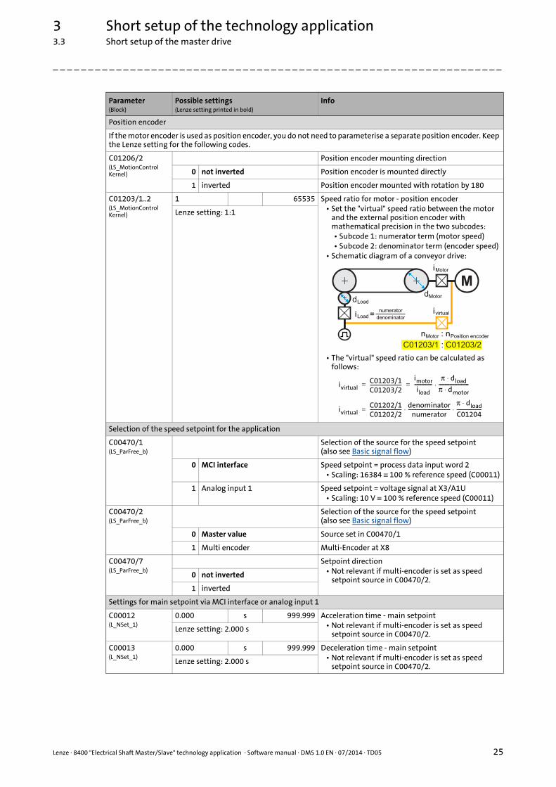
Position encoder
If the motor encoder is used as position encoder, you do not need to parameterise a separate position encoder. Keep the Lenze setting for the following codes.
C01206/2(LS_MotionControlKernel)
Position encoder mounting direction
0 not inverted Position encoder is mounted directly
1 inverted Position encoder mounted with rotation by 180
C01203/1..2(LS_MotionControlKernel)
1 65535 Speed ratio for motor - position encoder• Set the "virtual" speed ratio between the motor
and the external position encoder with mathematical precision in the two subcodes:• Subcode 1: numerator term (motor speed)• Subcode 2: denominator term (encoder speed)
• Schematic diagram of a conveyor drive:
• The "virtual" speed ratio can be calculated as follows:
Lenze setting: 1:1
Selection of the speed setpoint for the application
C00470/1(LS_ParFree_b)
Selection of the source for the speed setpoint(also see Basic signal flow)
0 MCI interface Speed setpoint = process data input word 2• Scaling: 16384 ≡ 100 % reference speed (C00011)
1 Analog input 1 Speed setpoint = voltage signal at X3/A1U• Scaling: 10 V ≡ 100 % reference speed (C00011)
C00470/2(LS_ParFree_b)
Selection of the source for the speed setpoint(also see Basic signal flow)
0 Master value Source set in C00470/1
1 Multi encoder Multi-Encoder at X8
C00470/7(LS_ParFree_b)
Setpoint direction• Not relevant if multi-encoder is set as speed
setpoint source in C00470/2.0 not inverted
1 inverted
Settings for main setpoint via MCI interface or analog input 1
C00012(L_NSet_1)
0.000 s 999.999 Acceleration time - main setpoint• Not relevant if multi-encoder is set as speed
setpoint source in C00470/2.Lenze setting: 2.000 s
C00013(L_NSet_1)
0.000 s 999.999 Deceleration time - main setpoint• Not relevant if multi-encoder is set as speed
setpoint source in C00470/2.Lenze setting: 2.000 s
Parameter(Block)
Possible settings(Lenze setting printed in bold)
Info
M
C01203/1 : C01203/2
: n
d
iLoadivirtual
iMotor
=numerator
denominator
Load
nMotor Position encoder
dMotor
ivirtualC01203/1C01203/2-------------------------
imotor
iload--------------
π dload⋅π dmotor⋅------------------------⋅= =
ivirtualC01202/1C01202/2------------------------- denominator
numerator----------------------------------
π dload⋅C01204--------------------⋅ ⋅=

3 Short setup of the technology application3.3 Short setup of the master drive
26 Lenze · 8400 "Electrical Shaft Master/Slave" technology application · Software manual · DMS 1.0 EN · 07/2014 · TD05
_ _ _ _ _ _ _ _ _ _ _ _ _ _ _ _ _ _ _ _ _ _ _ _ _ _ _ _ _ _ _ _ _ _ _ _ _ _ _ _ _ _ _ _ _ _ _ _ _ _ _ _ _ _ _ _ _ _ _ _ _ _ _ _
"Electrical shaft STOP" function
C01040/1(L_SRFG_1)
0.001 s 999.999 Linear ramp time for Electrical Shaft STOP• tramp =
C01040/1 * speed [%] + C01041/1Lenze setting: 0.5 s
C01041/1(L_SRFG_1)
0.001 s 50.000 S-ramp time for Electrical Shaft STOP
Lenze setting: 0.1 s
Stretch factor
C00471/1..2(LS_ParFree)
0 65535 Stretch factor• Subcode 1: numerator term• Subcode 2: denominator term
Lenze setting: 1000:1000
Gearbox factor
C00471/3..4(LS_ParFree)
0 65535 Gearbox factor• Subcode 1: numerator term• Subcode 2: denominator term
Lenze setting: 1000:1000
Speed trimming
C00476/1(LS_ParFree_a_2)
-199.99 % 199.99 Speed trimming positive• Scaling: 100 % ≡ reference speed (C00011)Lenze setting: 3 %
C00470/9(LS_ParFree_b)
Activate positive speed trimming
0 No speed trimming
1 Speed trimming by the value set in C00476/1
C00476/2(LS_ParFree_a_2)
-199.99 % 199.99 Speed trimming negative• Scaling: 100 % ≡ reference speed (C00011)Lenze setting: -3 %
C00470/10(LS_ParFree_b)
Activate negative speed trimming
0 No speed trimming
1 Speed trimming by the value set in C00476/2
Position offset (angular adjustment)
C00475/1(LS_ParFreeUnit_1)
-214748.3647 units 214748.3647 Position offset (X offset)The angular adjustment is retained as long as the position offset is present.
Lenze setting: 0.0000 units
C01060/2(L_PosCtrlLin_1)
0.010 s 130.000 Acceleration ramp for the higher-level positioning of the X axis via the position offset set in C00475/1.
Lenze setting: 1.000 s
C01060/3(L_PosCtrlLin_1)
0.010 s 130.000 Deceleration ramp for the higher-level positioning of the X axis via the position offset set in C00475/1.
Lenze setting: 1.000 s
Parameter(Block)
Possible settings(Lenze setting printed in bold)
Info

Lenze · 8400 "Electrical Shaft Master/Slave" technology application · Software manual · DMS 1.0 EN · 07/2014 · TD05 27
3 Short setup of the technology application3.3 Short setup of the master drive
_ _ _ _ _ _ _ _ _ _ _ _ _ _ _ _ _ _ _ _ _ _ _ _ _ _ _ _ _ _ _ _ _ _ _ _ _ _ _ _ _ _ _ _ _ _ _ _ _ _ _ _ _ _ _ _ _ _ _ _ _ _ _ _
3.3.5 Step 5: Go online and transfer parameter set to the inverter
In order to set the current parameter settings in the controller to the settings in the project, transmitthe parameter set to the controller.
1. Click the icon to go online.
2. Click the icon to transmit the parameter set to the controller.
3. After a successful transmission, click the icon to save the parameter set safe against mains failure in the integrated Memory Module.
Selection of the signal for slave drives to be output via axis bus
C00470/4(LS_ParFree_b)
Operation as position follower master
0 Off The signals are output via axis bus according to the settings in C00470/5 and C00470/6.
1 On This setting is only required if the drive is to be used as master for a slave drive with the "Position Follower" technology application. The following signals are then output via axis bus:Line data words 1 & 2 = current positionLine data word 3 = current speedNote:With this setting, homing of the master causes a step in the slave position follower if the current position is set to the home position!Remedy: Inhibit the slave position follower when you are referencing the master!
C00470/5(LS_ParFree_b)
Selection of the speed setpoint for slave drives(also see Basic signal flow)
0 Mere master value Speed setpoint set in C00470/2
1 Master value Speed setpoint of the master drive's motion control (speed setpoint of the Motion Control Kernel).With this setting, the slave drives follow the master drive even if it is executing manual jog or homing.
C00470/6(LS_ParFree_b)
Selection of the speed setpoint for slave drives(also see Basic signal flow)
0 Master value Master value set in C00470/5
1 Actual speed Current speed
Parameter(Block)
Possible settings(Lenze setting printed in bold)
Info

3 Short setup of the technology application3.4 Short setup of the slave drive
28 Lenze · 8400 "Electrical Shaft Master/Slave" technology application · Software manual · DMS 1.0 EN · 07/2014 · TD05
_ _ _ _ _ _ _ _ _ _ _ _ _ _ _ _ _ _ _ _ _ _ _ _ _ _ _ _ _ _ _ _ _ _ _ _ _ _ _ _ _ _ _ _ _ _ _ _ _ _ _ _ _ _ _ _ _ _ _ _ _ _ _ _
3.4 Short setup of the slave drive
The following steps are to be carried out for all slave drives of the interconnection.
3.4.1 Step 1: Load "Electrical Shaft Slave" technology application
In the Lenze setting, the inverter uses the "speed actuating drive" technology application integratedin the device. Execute the following steps to use the "Electrical Shaft Slave" technology applicationinstead:
1. Select the controller in the Project view.
2. If there is still an online connection to the controller:
Click the icon to go offline again.(the application can only be selected offline.)
3. Click the icon to select another application.The Insert application dialog box appears:
4. In the left field, select the "Packages" "Applications" category.
5. Select the "Electrical Shaft Slave" application in the right field.
6. Activate the Except motor data parameters option in order that the settings of the motor data parameters made before will not be overwritten.
7. Press Complete to close the dialog box again and load the selected application into the »Engineer« project.

Lenze · 8400 "Electrical Shaft Master/Slave" technology application · Software manual · DMS 1.0 EN · 07/2014 · TD05 29
3 Short setup of the technology application3.4 Short setup of the slave drive
_ _ _ _ _ _ _ _ _ _ _ _ _ _ _ _ _ _ _ _ _ _ _ _ _ _ _ _ _ _ _ _ _ _ _ _ _ _ _ _ _ _ _ _ _ _ _ _ _ _ _ _ _ _ _ _ _ _ _ _ _ _ _ _
8. Confirm the prompt on whether the current application is to be replaced by the "Electrical Shaft Slave" application with Yes.
3.4.2 Step 2: Axis bus settings for the slave
Make the following settings for every slave controller in the network:
• Axis bus address (C02430/1) = "2" ... "62"• Make sure that all controllers connected to the axis bus have different axis bus addresses.
• Sync signal source (C01120) = "2: AxisBusIO"• With this setting, the synchronisation cycle output by the master is used as synchronisation
source. The parameters C01121 ... C01123 for the synchronisation of the internal time base are automatically set to fixed reasonable values to provide for a technically perfect operation of the axis bus!
• Basically, only one source is allowed to synchronise the internal time base.
• Axis bus IO function (C02440/1) = "2: Slave"• This setting serves to define the slave.
3.4.3 Step 3 (optional): Set up control system via the fieldbus interface (MCI)
In the default setting, most functions are controlled via the digital input terminals.
Via the fieldbus interface (MCI), manual jog can be executed for the slave drive, and the X offset canbe deactivated. If further functions are to be controlled via the fieldbus interface (MCI), the userinterface (area highlighted in turquoise) must be adapted accordingly in the function block editor.
• The assignment of the outputs on the left to the inputs on the right can be changed at will.
• The inputs on the right are permanently linked to functions of the application.
Tip!
Control via the integrated CANopen interface ("CAN on board") can also be attained bymeans of simple interconnection changes. For this purpose, the LP_CanIn port block has tobe inserted in the interconnection and connected to the corresponding inputs of the userinterface.

3 Short setup of the technology application3.4 Short setup of the slave drive
30 Lenze · 8400 "Electrical Shaft Master/Slave" technology application · Software manual · DMS 1.0 EN · 07/2014 · TD05
_ _ _ _ _ _ _ _ _ _ _ _ _ _ _ _ _ _ _ _ _ _ _ _ _ _ _ _ _ _ _ _ _ _ _ _ _ _ _ _ _ _ _ _ _ _ _ _ _ _ _ _ _ _ _ _ _ _ _ _ _ _ _ _
3.4.4 Step 4: Set commissioning parameters
For a quick commissioning, only the following application-specific parameters have to be set ortheir default setting has to be checked!
• In order that you quickly find the respective parameterisation dialog in the FB Editor, the following table lists the block related to each parameter.
• The icon in the head of the module, a double-click on the module, or the Parameter... command in the Context menu of the module serve to open the parameterisation dialog or the parameter list for the module.
Parameter(Block)
Possible settings(Lenze setting printed in bold)
Info
Machine parameters/axis settings
C01201/1(LS_MotionControlKernel)
0.0000 units 214748.3647 Cycle length• For a modulo measuring system, the length of
one cycle to the overflow is to be set.• For a limited measuring system, the Lenze setting
"0.0000" is to be retained.
Lenze setting: 0.0000 units
C01204(LS_MotionControlKernel)
0.0001 units/rev.
214748.3647 Feed constant• The feed constant corresponds to the movement
of the machine during one revolution of the gearbox output shaft.
• The value is entered in application units relating to one gearbox revolution.
• Schematic diagram of a conveyor drive:
Lenze setting: 360.0000 units/U
C01206/1(LS_MotionControlKernel)
Motor mounting direction
0 not inverted Motor is mounted directly
1 inverted Motor is mounted with rotation by 180°
C01202/1..2(LS_MotionControlKernel)
1 65535 Gearbox ratio motor - load• Set the gearbox ratio with mathematical
precision in the two subcodes:• Subcode 1: numerator term (Z2)• Subcode 2: denominator term (Z1)
• Schematic diagram of a conveyor drive:
Lenze setting: 1:1
Md
C01204 = * d�
Motor
Motor
iMotorC01202/1C01202/2------------------------- Z2
Z1------= =
M
C01202/1 : C01202/2
Z2 : Z1
iMotor

Lenze · 8400 "Electrical Shaft Master/Slave" technology application · Software manual · DMS 1.0 EN · 07/2014 · TD05 31
3 Short setup of the technology application3.4 Short setup of the slave drive
_ _ _ _ _ _ _ _ _ _ _ _ _ _ _ _ _ _ _ _ _ _ _ _ _ _ _ _ _ _ _ _ _ _ _ _ _ _ _ _ _ _ _ _ _ _ _ _ _ _ _ _ _ _ _ _ _ _ _ _ _ _ _ _
Position encoder
If the motor encoder is used as position encoder, you do not need to parameterise a separate position encoder. Keep the Lenze setting for the following codes.
C01206/2(LS_MotionControlKernel)
Position encoder mounting direction
0 not inverted Position encoder is mounted directly
1 inverted Position encoder mounted with rotation by 180
C01203/1..2(LS_MotionControlKernel)
1 65535 Speed ratio for motor - position encoder• Set the "virtual" speed ratio between the motor
and the external position encoder with mathematical precision in the two subcodes:• Subcode 1: numerator term (motor speed)• Subcode 2: denominator term (encoder speed)
• Schematic diagram of a conveyor drive:
• The "virtual" speed ratio can be calculated as follows:
Lenze setting: 1:1
Error handling
C00470/4(LS_ParFree_b)
Error message to the masterFor commissioning of the slave drive, the error message to the master via the IO axis bus is deactivated at first.
0 deactivated
1 activated
Selection of the speed setpoint for the application
C00470/1(LS_ParFree_b)
Selection of the source for the speed setpoint
0 Axis bus Master drive
1 Multi encoder Multi-Encoder at X8
Stretch factor
C00471/1..2(LS_ParFree)
0 65535 Stretch factor• Subcode 1: numerator term• Subcode 2: denominator term
Lenze setting: 1000:1000
Gearbox factor
C00471/3..4(LS_ParFree)
0 65535 Gearbox factor• Subcode 1: numerator term• Subcode 2: denominator term
Lenze setting: 1000:1000
Speed trimming
C00476/1(LS_ParFree_a_2)
-199.99 % 199.99 Speed trimming positive• Scaling: 100 % ≡ reference speed (C00011)Lenze setting: 3 %
C00476/2(LS_ParFree_a_2)
-199.99 % 199.99 Speed trimming negative• Scaling: 100 % ≡ reference speed (C00011)Lenze setting: -3 %
Parameter(Block)
Possible settings(Lenze setting printed in bold)
Info
M
C01203/1 : C01203/2
: n
d
iLoadivirtual
iMotor
=numerator
denominator
Load
nMotor Position encoder
dMotor
ivirtualC01203/1C01203/2-------------------------
iMotor
iload--------------
π dload⋅π dMotor⋅------------------------⋅= =
ivirtualC01202/1C01202/2------------------------- denominator
numerator----------------------------------
π dload⋅C01204--------------------⋅ ⋅=

3 Short setup of the technology application3.5 Enabling the interconnection and specifying the speed setpoint
32 Lenze · 8400 "Electrical Shaft Master/Slave" technology application · Software manual · DMS 1.0 EN · 07/2014 · TD05
_ _ _ _ _ _ _ _ _ _ _ _ _ _ _ _ _ _ _ _ _ _ _ _ _ _ _ _ _ _ _ _ _ _ _ _ _ _ _ _ _ _ _ _ _ _ _ _ _ _ _ _ _ _ _ _ _ _ _ _ _ _ _ _
3.4.5 Step 5: Go online and transfer parameter set to the inverter
In order to set the current parameter settings in the controller to the settings in the project, transmitthe parameter set to the controller.
1. Click the icon to go online.
2. Click the icon to transmit the parameter set to the controller.
3. After a successful transmission, click the icon to save the parameter set safe against mains failure in the integrated Memory Module.
3.5 Enabling the interconnection and specifying the speed setpoint
After the parameter set has been transmitted to the inverter, the inverter can now be enabled andthe control signals/setpoints can be selected via the corresponding interfaces.
Pre-assignment of the user interface for the master drive ( 14)
Pre-assignment of the user interface for the slave drive ( 17)
Position offset (angular adjustment)
C00475/1(LS_ParFreeUnit)
-214748.3647 units 214748.3647 Position offset (X offset)The angular adjustment is reatined as long as the position offset is present and the slave is running in electrical shaft operation.
Lenze setting: 0.0000 units
C01060/2(L_PosCtrlLin_1)
0.010 s 130.000 Acceleration ramp for the higher-level positioning of the X axis via the position offset set in C00475/1.
Lenze setting: 1.000 s
C01060/3(L_PosCtrlLin_1)
0.010 s 130.000 Deceleration ramp for the higher-level positioning of the X axis via the position offset set in C00475/1.
Lenze setting: 1.000 s
Mark synchronisation/TP correction
C00470/3(LS_ParFree_b)
Mark synchronisation/TP correction
0 Off
1 On Permanent zero pulse/touch probe synchronisation. The correction is carried out by the shortest path.(Other synchronisation modes can be selected in C01075/1)
C01069/2(L_DFSET_1)
0 Incr./ms
32767 Correction width (ramp for angle compensation)The increments for the angle compensation in the case of mark synchronisation are specified in the Lenze setting with downstream 3rd-order polynomial.
Lenze setting: 100 incr./ms
Parameter(Block)
Possible settings(Lenze setting printed in bold)
Info

Lenze · 8400 "Electrical Shaft Master/Slave" technology application · Software manual · DMS 1.0 EN · 07/2014 · TD05 33
3 Short setup of the technology application3.6 (Optionally): Setting the optimisation parameters
_ _ _ _ _ _ _ _ _ _ _ _ _ _ _ _ _ _ _ _ _ _ _ _ _ _ _ _ _ _ _ _ _ _ _ _ _ _ _ _ _ _ _ _ _ _ _ _ _ _ _ _ _ _ _ _ _ _ _ _ _ _ _ _
3.6 (Optionally): Setting the optimisation parameters
The following application-specific parameters are used for optimisation and can also be adaptedduring operation.
Tip!
Do not forget to save the parameter changes carried out with mains failure protection inthe memory module implemented! (C00002/11 = "1: on/start")
3.6.1 Optimisation parameters for the master drive
The following parameters have already been set in step 4. However, depending on the applicationit may be required to change the settings again during operation:
3.6.2 Optimisation parameters for the slave drive
Stop!
If you change parameters in the »Engineer« during an online connection to the device, the changes are directly transferred to the device!
Parameter(Block)
Possible settings Info
Settings for main setpoint via MCI interface or analog input 1
C00012(L_NSet_1)
0.000 s 999.999 Acceleration time - main setpoint• Not relevant if multi-encoder is set as speed
setpoint source in C00470/2.Lenze setting: 2.000 s
C00013(L_NSet_1)
0.000 s 999.999 Deceleration time - main setpoint• Not relevant if multi-encoder is set as speed
setpoint source in C00470/2.Lenze setting: 2.000 s
"Electrical shaft STOP" function
C01040/1(L_SRFG_1)
0.001 s 999.999 Linear ramp time for Electrical Shaft STOP• tramp =
C01040/1 * speed [%] + C01041/1Lenze setting: 0.5 s
C01041/1(L_SRFG_1)
0.001 s 50.000 S-ramp time for Electrical Shaft STOP
Lenze setting: 0.1 s
Parameter(Block)
Possible settings Info
Following error monitoring system
C00254(LS_MotorInterface)
0.00 1/s 500.00 Kp position controller• Gain for following error compensationLenze setting: 5.00/s
C01215/1(LS_MotionControlKernel)
0.0001 units 214748.3647 Limit for following error monitoring 1• The setting "0" deactivates following error
monitoring 1Lenze setting: 5.0000 units
C01215/2(LS_MotionControlKernel)
0.0001 units 214748.3647 Limit for following error monitoring 2• The setting "0" deactivates following error
monitoring 2Lenze setting: 10.0000 units

4 Detailed functions of the technology application4.1 Basic drive functions (MCK)
34 Lenze · 8400 "Electrical Shaft Master/Slave" technology application · Software manual · DMS 1.0 EN · 07/2014 · TD05
_ _ _ _ _ _ _ _ _ _ _ _ _ _ _ _ _ _ _ _ _ _ _ _ _ _ _ _ _ _ _ _ _ _ _ _ _ _ _ _ _ _ _ _ _ _ _ _ _ _ _ _ _ _ _ _ _ _ _ _ _ _ _ _
4 Detailed functions of the technology application
4.1 Basic drive functions (MCK)
4.1.1 Homing
In some applications it is required that the master and slave drive are aligned with each other beforethe actual synchronous operation starts. This can for instance be effected by homing or a referencesearch. This so-called "homing" is usually carried out after mains connection. Furthermore, homingafter the elimination of an encoder error is required.
• "Manual" start/stop of the homing process is executed via bit 6 of the application control word (FB L_ConvBitsToWord_1).• In the case of the master, this bit is linked with digital input DI1 in the default setting.• In the case of the slave, this bit is linked with digital input DI6 in the default setting.
• Homing is to be configured according to the requirement of the application, as described in the reference manual/online help of the inverter.
• If the home position is known to the drive, a response is sent via digital output DO3 and bit 15 of the MCI process data output word 1.
Danger!
During homing, manual jog, and positioning, specially assigned profile parameters are active. If they have not been set correctly, the drive may carry out an unexpected movement!
Detailed information relating to the basic drive functions and the corresponding parameters can be found in the reference manual/online help of the inverter in the "Basic drive functions (MCK)" chapter.
Note!
Depending on the configuration of the master drive, the slave will follow the master during a homing process, or it won't. Therefore it depends on the application whether it is reasonable to, for example, first reference the master and then the slave. If the slave is not to follow the master during the homing process, quick stop (QSP) is to be activated for the slave.

Lenze · 8400 "Electrical Shaft Master/Slave" technology application · Software manual · DMS 1.0 EN · 07/2014 · TD05 35
4 Detailed functions of the technology application4.1 Basic drive functions (MCK)
_ _ _ _ _ _ _ _ _ _ _ _ _ _ _ _ _ _ _ _ _ _ _ _ _ _ _ _ _ _ _ _ _ _ _ _ _ _ _ _ _ _ _ _ _ _ _ _ _ _ _ _ _ _ _ _ _ _ _ _ _ _ _ _
How to go to the parameterisation dialog of the basic "Homing" function:
1. Open the parameter list for the LS_MotionControlKernel SB.
2. In the Block Parameters List... dialog box on the Application Parameters tab, select the "Homing" entry in the upper list field.
Note!
For a reference search with touch probe detection:
If the reference signal is to follow a real touch probe, the touch probe interface must be configured accordingly via the Setting up TouchProbe... button!
Parameter Info Lenze setting
Value Unit
C01221 MCK: Homing mode 8: >_TP
C01224/1 MCK: Ref. initial speed 100.0000 unit/s
C01225/1 MCK: Ref. initial acceleration 720.0000 unit/s2
C01224/2 MCK: Ref. search speed 180.0000 unit/s
C01225/2 MCK: Ref. search acceleration 720.0000 unit/s2
C01226/1 MCK: Ref. S-ramp time 0.000 s

4 Detailed functions of the technology application4.1 Basic drive functions (MCK)
36 Lenze · 8400 "Electrical Shaft Master/Slave" technology application · Software manual · DMS 1.0 EN · 07/2014 · TD05
_ _ _ _ _ _ _ _ _ _ _ _ _ _ _ _ _ _ _ _ _ _ _ _ _ _ _ _ _ _ _ _ _ _ _ _ _ _ _ _ _ _ _ _ _ _ _ _ _ _ _ _ _ _ _ _ _ _ _ _ _ _ _ _
4.1.2 Manual jog
In this operating mode, the drive can be traversed manually in a clockwise or anticlockwise direction("jogging mode").
• The basic "Manual jog" function is activated via bit 12 and bit 13 of the application control word (FB L_ConvBitsToWord_1).• In the case of the master, these two bits are linked with digital inputs DI5 and DI6 in the
default setting.• In the case of the slave, these two bits are linked bit 12 and bit 13 of the MCI process data
input word 1 in the default setting.
C01222 MCK: Ref. M limit mode 14/15 10.00 %
C01223 MCK: Ref. waiting time mode 14/15 100 ms
C01227/1 MCK: Ref. offset reference degree 0.0000 unit
C01227/2 MCK: Ref. home position 0.0000 unit
C01228 MCK: Ref. sequence profile 0
C01229/1 MCK: Positive SW limit position 0.0000 units
C01229/2 MCK: Negative SW limit position 0.0000 units
C01246/1 MCK: Ref. TP signal source 0: No TP
Parameter Info Lenze setting
Value Unit

Lenze · 8400 "Electrical Shaft Master/Slave" technology application · Software manual · DMS 1.0 EN · 07/2014 · TD05 37
4 Detailed functions of the technology application4.1 Basic drive functions (MCK)
_ _ _ _ _ _ _ _ _ _ _ _ _ _ _ _ _ _ _ _ _ _ _ _ _ _ _ _ _ _ _ _ _ _ _ _ _ _ _ _ _ _ _ _ _ _ _ _ _ _ _ _ _ _ _ _ _ _ _ _ _ _ _ _
How to go to the parameterisation dialog of the basic "Manual jog" function:
1. Open the parameter list for the LS_MotionControlKernel SB.
2. In the Block Parameters List... dialog box on the Application Parameters tab, select the "Manual Jog" entry in the upper list field.
Parameter Info Lenze setting
Value Unit
C01230 MCK: Manual jog setting Bit coded
C01231/1 Manual jog: speed 1 1000.0000 units/s
C01231/2 Manual jog: Speed 2 720.0000 units/s
C01232/1 Manual jog: Acceleration 720.0000 units/s2
C01232/2 Manual jog: Deceleration 720.0000 units/s2
C01233/1 Manual jog: S-ramp time 0.000 s
C01235/1 Waiting time 2nd speed 5.000 s
C01234/1 Manual jog: Breakpoint 1 0.0000 unit
C01234/2 Manual jog: Breakpoint 2 0.0000 unit
C01234/3 Manual jog: Breakpoint 3 0.0000 unit
C01234/4 Manual jog: Breakpoint 4 0.0000 unit

4 Detailed functions of the technology application4.1 Basic drive functions (MCK)
38 Lenze · 8400 "Electrical Shaft Master/Slave" technology application · Software manual · DMS 1.0 EN · 07/2014 · TD05
_ _ _ _ _ _ _ _ _ _ _ _ _ _ _ _ _ _ _ _ _ _ _ _ _ _ _ _ _ _ _ _ _ _ _ _ _ _ _ _ _ _ _ _ _ _ _ _ _ _ _ _ _ _ _ _ _ _ _ _ _ _ _ _
4.1.3 Holding brake control
This basic function is used for low-wear control of a holding brake.
Application-specific notes on the holding brake control:
• In the Lenze setting, the mode 0 (brake control off) is preset in C02580.
• The technology application is prepared for the control of a 24-V holding brake via the high current output.
• In the "Homing" and "Manual jog" operating modes, the holding brake is released automatically by the MCK. In the "Speed follower" operating mode, release of the brake is effected by the application. For the master by the L_DigitalLogic5_1 FB, for the slave by FBs L_Or5_2 and L_Not_2.
• For the slave drive, the switching threshold for releasing the brake is set in C02581/1.
Danger!
Please note that the holding brake is an important element of the safety concept of the entire machine.
Thus, proceed very carefully when commissioning this system part!
In order to ensure that the brake is not released unintentionally while the application is transferred to the inverter, we recommend unplugging the brake connector X107 during the transfer.
Detailed information on how to parameterise the holding brake control can be found in the reference manual/online help of the controller in the chapter "Basic drive functions (MCK)".
The documentation of the holding brake control contains safety instructions which must be observed!

Lenze · 8400 "Electrical Shaft Master/Slave" technology application · Software manual · DMS 1.0 EN · 07/2014 · TD05 39
4 Detailed functions of the technology application4.2 Functions in the master drive
_ _ _ _ _ _ _ _ _ _ _ _ _ _ _ _ _ _ _ _ _ _ _ _ _ _ _ _ _ _ _ _ _ _ _ _ _ _ _ _ _ _ _ _ _ _ _ _ _ _ _ _ _ _ _ _ _ _ _ _ _ _ _ _
4.2 Functions in the master drive
4.2.1 Selection of the setpoint signal for the slave drives
For the speed/position output to the slave drives, SB LS_AxisBusOut is provided in the masterapplication.
• In the default setting, the speed setpoint integrated to an angle (path) is output via line data words 1 & 2, and the speed setpoint is output via line data word 3.
• A slave drive connected via axis bus with the "Electrical Shaft Slave" technology application is executable immediately after the initialisation of the axis bus if no fault is pending.• If a fault is pending in the slave drive, the cause of which, however, has been eliminated, this
error can be reset via reset of the master.
• If the drive is to be used as master for a slave drive with the "Position Follower" technology application, set the value "1" in C00470/4. Then, instead of the speed integrated, the current position is output via axis bus.
The signal to be output via axis bus is selected using C00470/4...6:
Details on the signal flow
Switch-over between the different setpoint signals for the slave drives is effected viaFBs L_SignalSwitch_2...4.
In the default setting C00470/4 = 0, the position value for SB LS_AxisBusOut is generated with theL_PhaseIntK_1 FB. Loading or a reset is not required, since in the slave drive merely consistency withthe speed value is compared without attaching importance to the absolute value.
With the setting C00470/4 = 1 (operation as master position follower), as position value forSB LS_AxisBusOut the current position dnMotorPosAct_p is used by the LS_MotorInterface SB.
Stop!
If operation as master position follower is switched on (C00470/4 = "1"), homing of the master causes a step for the slave position follower if the current position is set to the home position!
Remedy: Inhibit the slave position follower when you reference the master!
C00470/4 C00470/6 C00470/5 Axis bus output
Operation as position follower
master
Selection of master value/
actual speed
Selection of mere master value
0 Off 0 Master value 0 Mere master value
Line data words 1 & 2 = speed setpoint integrated to an angle (path)Line data word 3 = speed setpoint
1 Master value Line data words 1 & 2 = speed setpoint integrated to an angle (path) from the MCKLine data word 3 = speed setpoint from the MCK
1 Actual speed Line data words 1 & 2 = current speed integrated to an angle (path)Line data word 3 = current speed
1 On Line data words 1 & 2 = current positionLine data word 3 = current speed

4 Detailed functions of the technology application4.2 Functions in the master drive
40 Lenze · 8400 "Electrical Shaft Master/Slave" technology application · Software manual · DMS 1.0 EN · 07/2014 · TD05
_ _ _ _ _ _ _ _ _ _ _ _ _ _ _ _ _ _ _ _ _ _ _ _ _ _ _ _ _ _ _ _ _ _ _ _ _ _ _ _ _ _ _ _ _ _ _ _ _ _ _ _ _ _ _ _ _ _ _ _ _ _ _ _
4.2.2 "Electrical shaft STOP" function
When the "Electrical shaft STOP" function is activated in the master, all slave drives enabled remainsynchronous, since this function has a direct impact on the master value path. When the "Quick stop(QSP)" function is activated in the master, however, it depends on the setting in C00104/1 whetherthe drive is brought to a standstill in an angle-controlled manner or not.
A further characteristic of the "Electrical shaft STOP" function is that a torque limitation which ispossibly set via the following parameters is continued to be taken into consideration:
Tip!
Depending on the application, the "Electrical Shaft Stop" function can be used for anoperation stop, and the "quick stop (QSP)" function for an emergency stop.
Parameter(Block)
Possible settings Info
Torque limitation in motor mode/in generator mode
The torque limitation set is always active. Example: Definition of the torque limitations
C00472/3(LS_ParFree_a)
-199.99 % 199.99 Torque limitation in motor mode
Lenze setting: 100 % maximum torque (C00057)
C00472/4(LS_ParFree_a)
-199.99 % 199.99 Torque limitation in generator mode
Lenze setting: 100 % maximum torque (C00057)
M
n
50 %
-100 % 100 %50 %
C00472/3 = 25 %
-50 %
25 %
-50 %
-25 %
C00472/4 = 50 %
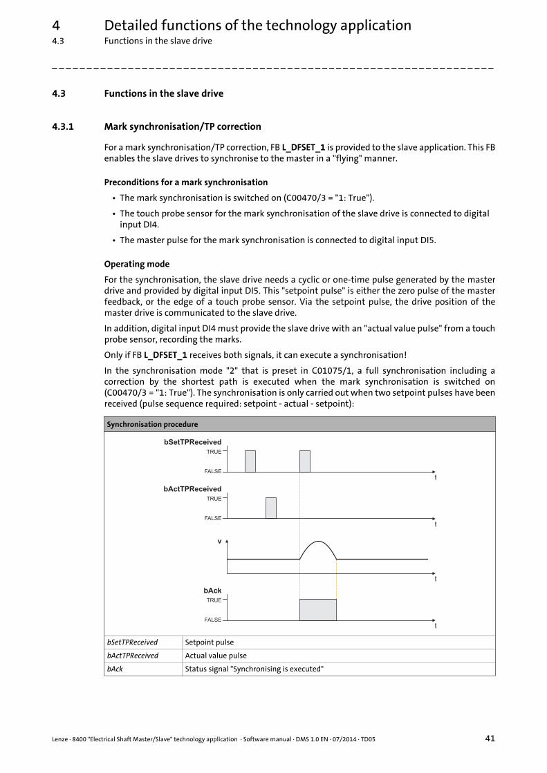
Lenze · 8400 "Electrical Shaft Master/Slave" technology application · Software manual · DMS 1.0 EN · 07/2014 · TD05 41
4 Detailed functions of the technology application4.3 Functions in the slave drive
_ _ _ _ _ _ _ _ _ _ _ _ _ _ _ _ _ _ _ _ _ _ _ _ _ _ _ _ _ _ _ _ _ _ _ _ _ _ _ _ _ _ _ _ _ _ _ _ _ _ _ _ _ _ _ _ _ _ _ _ _ _ _ _
4.3 Functions in the slave drive
4.3.1 Mark synchronisation/TP correction
For a mark synchronisation/TP correction, FB L_DFSET_1 is provided to the slave application. This FBenables the slave drives to synchronise to the master in a "flying" manner.
Preconditions for a mark synchronisation
• The mark synchronisation is switched on (C00470/3 = "1: True").
• The touch probe sensor for the mark synchronisation of the slave drive is connected to digital input DI4.
• The master pulse for the mark synchronisation is connected to digital input DI5.
Operating mode
For the synchronisation, the slave drive needs a cyclic or one-time pulse generated by the masterdrive and provided by digital input DI5. This "setpoint pulse" is either the zero pulse of the masterfeedback, or the edge of a touch probe sensor. Via the setpoint pulse, the drive position of themaster drive is communicated to the slave drive.
In addition, digital input DI4 must provide the slave drive with an "actual value pulse" from a touchprobe sensor, recording the marks.
Only if FB L_DFSET_1 receives both signals, it can execute a synchronisation!
In the synchronisation mode "2" that is preset in C01075/1, a full synchronisation including acorrection by the shortest path is executed when the mark synchronisation is switched on(C00470/3 = "1: True"). The synchronisation is only carried out when two setpoint pulses have beenreceived (pulse sequence required: setpoint - actual - setpoint):
Synchronisation procedure
bSetTPReceived Setpoint pulse
bActTPReceived Actual value pulse
bAck Status signal "Synchronising is executed"
TRUE
FALSE
bAck
t
v
t
t
TRUE
FALSE
bSetTPReceived
t
TRUE
FALSE
bActTPReceived

4 Detailed functions of the technology application4.3 Functions in the slave drive
42 Lenze · 8400 "Electrical Shaft Master/Slave" technology application · Software manual · DMS 1.0 EN · 07/2014 · TD05
_ _ _ _ _ _ _ _ _ _ _ _ _ _ _ _ _ _ _ _ _ _ _ _ _ _ _ _ _ _ _ _ _ _ _ _ _ _ _ _ _ _ _ _ _ _ _ _ _ _ _ _ _ _ _ _ _ _ _ _ _ _ _ _
Compensation process
At the input of the second setpoint or actual value pulse, the difference between the master andslave psition is determined. This difference is then transferred via the speed output nSpeedSetOut_vas an additive offset to the Motion Control Kernel. The compensating movement is smoothened bymeans of a polynomial.
The following illustration shows a compensating process after the marks have been detected. Thespeed is added here as a parabola to the line speed. (The scaling in this diagram does not correspondto reality)
Example: Compensation process
Detailed information about the L_DFSET_1 FB can be found in the reference manual/online help of the inverter in the "Function library" chapter.
nSpeedSetOut_v dnPosDiffOut_p
t
v

Lenze · 8400 "Electrical Shaft Master/Slave" technology application · Software manual · DMS 1.0 EN · 07/2014 · TD05 43
4 Detailed functions of the technology application4.4 Monitoring functions
_ _ _ _ _ _ _ _ _ _ _ _ _ _ _ _ _ _ _ _ _ _ _ _ _ _ _ _ _ _ _ _ _ _ _ _ _ _ _ _ _ _ _ _ _ _ _ _ _ _ _ _ _ _ _ _ _ _ _ _ _ _ _ _
4.4 Monitoring functions
4.4.1 Following error monitoring system
The difference between set position and actual position is called the following error. Ideally, thefollowing error should be "0". The set position is created by the internal definition of the traversingprofiles of the Motion Control Kernel. The actual position is created by the integration of the speedsupplied by the position encoder. If the position control is adjusted optimally, only a minimumfollowing error arises which is always compensated dynamically and not increases continuously.
Certain processes, however, require that a defined limit as a difference between set position andactual position is not exceeded. If it is exceeded, it may have been caused by a mechanical blockingin the machine and the system part is not situated at the position defined at that time. In such acase, it makes sense to activate the "Fault" error response to make the motor torqueless.
In the 8400 TopLine controller, two independent following error monitoring systems can beparameterised:
[4-1] Two-channel following error monitoring system
Parameter(Block)
Possible settings Info
C01215/1(LS_MotionControlKernel)
0.0001 units 214748.3647 Limit for following error monitoring 1• The setting "0" deactivates following error
monitoring 1Lenze setting: 5.0000 units
C01215/2(LS_MotionControlKernel)
0.0001 units 214748.3647 Limit for following error monitoring 2• The setting "0" deactivates following error
monitoring 2Lenze setting: 10.0000 units
C01244/2...3(LS_MotionControlKernel)
0 ms 600000 Waiting time for following error monitoring 1 & 2• In order to avoid that an error is triggered by
acceleration and a narrow tolerance limit can be nevertheless monitored at standstill in the target, the response of the following error monitoring system can be delayed by setting a waiting time.
Lenze setting: 0 ms
C00595/5...6(LS_SetError_1)
Response at the activation of following error monitoring
• Subcode 5: response at the activation of following error monitoring 1.
• Subcode 6: response at the activation of following error monitoring 2.
0 No Reaction
1 Fault
3 TroubleQuickStop
4 WarningLocked
5 Warning
6 Information

4 Detailed functions of the technology application4.4 Monitoring functions
44 Lenze · 8400 "Electrical Shaft Master/Slave" technology application · Software manual · DMS 1.0 EN · 07/2014 · TD05
_ _ _ _ _ _ _ _ _ _ _ _ _ _ _ _ _ _ _ _ _ _ _ _ _ _ _ _ _ _ _ _ _ _ _ _ _ _ _ _ _ _ _ _ _ _ _ _ _ _ _ _ _ _ _ _ _ _ _ _ _ _ _ _
The above example clearly shows that there are two monitoring functions acting independently ofeach other. Normally, one following error monitoring function with a low tolerance is set aswarning, and the other with a higher tolerance is set as TroubleQuickStop.
By means of the waiting times (C1244/2 and C1244/3), the error responses can be delayed, so thatdisconnection does not result immediately when the following error limits are temporarilyexceeded. This "switch-on delay" makes it possible to effectively distinguish between dynamicprocesses and actual error states such as mechanical obstacles or sluggishness.
Example of the evaluation of the following error
Target position Limit for following error monitoring 1 (C01215/1)
Position actual value Limit for following error monitoring 2 (C01215/2)
Current following error Waiting time for following error monitoring 1 (C01244/2)
Waiting time for following error monitoring 2 (C01244/3)
�
�
�
�
�
t
t
t
t
�
�
�
�
�
Position
Following error
Ck05:1Following error
Ck06:2Following error

Lenze · 8400 "Electrical Shaft Master/Slave" technology application · Software manual · DMS 1.0 EN · 07/2014 · TD05 45
4 Detailed functions of the technology application4.4 Monitoring functions
_ _ _ _ _ _ _ _ _ _ _ _ _ _ _ _ _ _ _ _ _ _ _ _ _ _ _ _ _ _ _ _ _ _ _ _ _ _ _ _ _ _ _ _ _ _ _ _ _ _ _ _ _ _ _ _ _ _ _ _ _ _ _ _
4.4.2 Limit position monitoring
For safety reasons, drives with a limited traversing range must always be made safe usingcorresponding safety mechanisms. These are firstly the hardware limit switches, which must effecta standstill of the axes as quickly as possible during the approaching process. In addition, theparameterisable software limit positions are to inhibit all travel commands which would entail anexit of the permissible travel range.
Take the following items into consideration for placing the limit positions:
• The hardware limit switches must be mounted with a sufficient clearance in front of the mechanical limit positions of the linear axis. The clearance to the mechanical limit position should be calculated for a quick stop (QSP) from maximum speed, so that in the event of an error, standstill is attained safely before the mechanical limit position is reached.
• The software limit positions must be placed with a sufficient distance from the hardware limit switch positions. The distance should be calculated for a quick stop (QSP) from maximum speed without the hardware limit switches being approached.
4.4.2.1 Hardware limit switch
For an evaluation of hardware limit switches, the two digital inputs in the function block editor thatare used for the connection of the hardware limit switches have to be connected to the monitoringinputs bLimitSwitchNeg and bLimitSwitchPos of the LS_MotionControlKernel system block.
The following example exemplarily shows the connections required if the negative limit switch isconnected to digital input DI1 and the positive limit switch is connected to digital input DI2:
1. LS_DigitalInput.bIn1 LS_MotionControlKernel.bLimitSwitchNeg
2. LS_DigitalInput.bIn2 LS_MotionControlKernel.bLimitSwitchPos
Note!
In the two technology applications "Electrical Shaft Master" and "Electrical Shaft Slave", an evaluation of hardware limit switches is not prepared by default yet, but it can be retrofitted in a few steps if required (see "Hardware limit switch" subchapter).
Stop!
The connection of the limit switch signals must be executed in a fail-safe fashion:• LOW level = limit switch approached (activated)• HIGH level = limit switch not approached (not activated)
To obtain this switching logic, the level inversion for the two digital inputs to which the limit switches are connected has to be activated in C00114!
The limit switches are only evaluated if the limit switches for the respective operating mode have been activated (see the following table)!
Operating mode Hardware limit switch effective
Speed follower Yes (adjustable in C01219 - bit 2)
Homing Depending on the homing mode selected(see description of the homing modes in the reference manual/online help of the inverter)
Manual jog No (adjustable in C01230 - bit 2)

4 Detailed functions of the technology application4.4 Monitoring functions
46 Lenze · 8400 "Electrical Shaft Master/Slave" technology application · Software manual · DMS 1.0 EN · 07/2014 · TD05
_ _ _ _ _ _ _ _ _ _ _ _ _ _ _ _ _ _ _ _ _ _ _ _ _ _ _ _ _ _ _ _ _ _ _ _ _ _ _ _ _ _ _ _ _ _ _ _ _ _ _ _ _ _ _ _ _ _ _ _ _ _ _ _
Behaviour when hardware limit switches are active
If one of the two monitoring inputs is set to TRUE, in the Lenze setting the "TroubleQuickStop" errorresponse is triggered: Irrespective of the setpoint selection, the drive is brought to a standstill in thedeceleration time set for the quick stop function. Depending on the error response parameterised,the drive can then only be traversed again after the error has been acknowledged.
4.4.2.2 Software limit positions
The parameterisable limit positions are used by the software to limit the traversing range.
Positioning Yes
Stop Yes
Position follower Yes (adjustable in C01218 - bit 2)
Parameter(Block)
Possible settings Info
C00595/1...2(LS_MotionControlKernel)
Response at the activation of limit position monitoring
• Subcode 1: response at the approach of the positive limit switch.
• Subcode 2: response at the approach of the negative limit switch.
0 No Reaction
1 Fault
3 TroubleQuickStop
4 WarningLocked
5 Warning
6 Information
Operating mode Hardware limit switch effective
Stop!
The software limit positions are only evaluated and monitored if the home position is known to the drive and the software limit positions for the respective operating mode have been activated (see following table)!
Operating mode Software limit positions active (if home position is known)
Speed follower Yes (adjustable in C01219 - bit 3)
Homing Yes
Manual jog Yes (adjustable in C01230 - bit 3)
Positioning Yes
Position follower Yes (adjustable in C01218 - bit 3)
Parameter(Block)
Possible settings Info
C01229/1...2(LS_MotionControlKernel)
-214748.3647 units 214748.3647 Positive and negative software limit position for limiting the valid traversing range
• The positive software limit position must be set to a greater value than the negative software limit position!
Lenze setting: 0.0000 units

Lenze · 8400 "Electrical Shaft Master/Slave" technology application · Software manual · DMS 1.0 EN · 07/2014 · TD05 47
4 Detailed functions of the technology application4.4 Monitoring functions
_ _ _ _ _ _ _ _ _ _ _ _ _ _ _ _ _ _ _ _ _ _ _ _ _ _ _ _ _ _ _ _ _ _ _ _ _ _ _ _ _ _ _ _ _ _ _ _ _ _ _ _ _ _ _ _ _ _ _ _ _ _ _ _
Behaviour in the case of active software limit positions
If the software limit positions are active, travelling commands that would result in the exit from thepermissible travel range can no longer be executed.
If the drive is already outside the permissible travel range and the software limit positions havebeen activated, only travel commands that result in the drive moving back into the permissibletravel range can be executed.
If the software limit positions are active, and one of the software limit positions is overtravelled, inthe Lenze setting the "TroubleQuickStop" error response is triggered: Irrespective of the setpointselection, the drive is brought to a standstill in the deceleration time set for the quick stop function.Depending on the error response parameterised, the drive can then only be traversed again after theerror has been acknowledged.
C00595/3...4(LS_MotionControlKernel)
Response at the activation of limit position monitoring
• Subcode 3: response at overtravelling the positive software limit position (C01229/1).
• Subcode 4: response at overtravelling the negative software limit position (C01229/2).
0 No Reaction
1 Fault
3 TroubleQuickStop
4 WarningLocked
5 Warning
6 Information
Note!
The "travel commands" mentioned in the following description are no speed setpoint selections. In the "Speed follower" and "Position follower" operating modes, an acknowledged software limit position error ensures that traversing to the impermissible travel range remains possible afterwards. This is because in these two operating modes, there is no preview of whether a software limit position is approached with a setpoint selection.
Parameter(Block)
Possible settings Info

4 Detailed functions of the technology application4.4 Monitoring functions
48 Lenze · 8400 "Electrical Shaft Master/Slave" technology application · Software manual · DMS 1.0 EN · 07/2014 · TD05
_ _ _ _ _ _ _ _ _ _ _ _ _ _ _ _ _ _ _ _ _ _ _ _ _ _ _ _ _ _ _ _ _ _ _ _ _ _ _ _ _ _ _ _ _ _ _ _ _ _ _ _ _ _ _ _ _ _ _ _ _ _ _ _
4.4.3 Bus monitoring
When an "electrical shaft" is executed via axis bus, or generally via a bus system, one always has toexpect data transmission errors, for example due to EMC interference. In order to prevent amechanical offset of the drives in the case of even a temporary fault, the L_Interpolator_1 FB is usedin the slave application. This FB is provided with an internal correction mechanism which arrangesfor an automatic offset correction if a data telegram is missing. Like this, the axis bus monitoringtime (C02431/3) can be set to an insensitive value, so that a very robust transmission system iscreated.
Parameterisation of the error handling:
Parameter Possible settings Info
C00591/1 Resp. to axis bus data error• Response in the case of an accumulation of data
errors0 No Reaction
1 Fault
2 Trouble
3 TroubleQuickStop
4 WarningLocked
5 Warning
6 Information
C00591/2 Resp. to axis bus IO error• Response in the case of an I/O error ("release cord"
function)0 No Reaction
1 Fault
2 Trouble
3 TroubleQuickStop
4 WarningLocked
5 Warning
6 Information
C02431/3 0 ms 65000 Axis bus monitoring timeTolerance time before the data error is triggeredLenze setting: 1000 ms
C02444/1 Axis bus configuration
Bit 0 Edge detection SetFail 1 ≡ input bSetFail_DigOut is edge-sensitive.0 ≡ input bSetFail_DigOut is level-sensitive.
Bit 1 Reserved Not relevant for bus monitoring
... Reserved
Bit 13 Reserved
Bit 14 same CobId for all Cas
Bit 15 500 kbps

49
Your opinion is important to usThese instructions were created to the best of our knowledge andbelief to give you the best possible support for handling our product.
If you have suggestions for improvement, please e-mail us to:
Thank you for your support.
Your Lenze documentation team

L
8400 "Electrical Shaft Master/Slave" technology application · Software manual · 13467297 · DMS 1.0 EN · 07/2014 · TD05
Lenze Drives GmbHBreslauer Straße 3D-32699 ExtertalGermany
+49 5154 82-0 [email protected] www.lenze.com
ServiceLenze Service GmbHBreslauer Straße 3D-32699 ExtertalGermany
008000 24 46877 (24 h helpline) +49 5154 82-1112 [email protected]