software manual 8400 position follower technology applicationdownload.lenze.com/td/8400 position...
TRANSCRIPT
L
Ä.Oj"ä
1346
7301
8400
Inverter
"Position Follower" technology applicationfor 8400 TopLine C _ _ _ _ _ _ _ _ _ _ _ _ _ _ _ Software manual EN
Contents
2 Lenze · 8400 "Position Follower" technology application · Software manual · DMS 1.0 EN · 07/2014 · TD05
_ _ _ _ _ _ _ _ _ _ _ _ _ _ _ _ _ _ _ _ _ _ _ _ _ _ _ _ _ _ _ _ _ _ _ _ _ _ _ _ _ _ _ _ _ _ _ _ _ _ _ _ _ _ _ _ _ _ _ _ _ _ _ _
1 About this documentation _ _ _ _ _ _ _ _ _ _ _ _ _ _ _ _ _ _ _ _ _ _ _ _ _ _ _ _ _ _ _ _ _ _ _ _ _ _ _ 31.1 Document history _ _ _ _ _ _ _ _ _ _ _ _ _ _ _ _ _ _ _ _ _ _ _ _ _ _ _ _ _ _ _ _ _ _ _ _ _ _ _ _ _ _ _ _ 31.2 Conventions used _ _ _ _ _ _ _ _ _ _ _ _ _ _ _ _ _ _ _ _ _ _ _ _ _ _ _ _ _ _ _ _ _ _ _ _ _ _ _ _ _ _ _ _ 41.3 Terminology used _ _ _ _ _ _ _ _ _ _ _ _ _ _ _ _ _ _ _ _ _ _ _ _ _ _ _ _ _ _ _ _ _ _ _ _ _ _ _ _ _ _ _ _ 51.4 Definition of notes used _ _ _ _ _ _ _ _ _ _ _ _ _ _ _ _ _ _ _ _ _ _ _ _ _ _ _ _ _ _ _ _ _ _ _ _ _ _ _ _ _ 6
2 Features of the technology application _ _ _ _ _ _ _ _ _ _ _ _ _ _ _ _ _ _ _ _ _ _ _ _ _ _ _ _ _ _ _ _ 72.1 Functional overview _ _ _ _ _ _ _ _ _ _ _ _ _ _ _ _ _ _ _ _ _ _ _ _ _ _ _ _ _ _ _ _ _ _ _ _ _ _ _ _ _ _ _ 72.2 Application ranges _ _ _ _ _ _ _ _ _ _ _ _ _ _ _ _ _ _ _ _ _ _ _ _ _ _ _ _ _ _ _ _ _ _ _ _ _ _ _ _ _ _ _ _ 82.3 System requirements _ _ _ _ _ _ _ _ _ _ _ _ _ _ _ _ _ _ _ _ _ _ _ _ _ _ _ _ _ _ _ _ _ _ _ _ _ _ _ _ _ _ 82.4 Basic signal flow _ _ _ _ _ _ _ _ _ _ _ _ _ _ _ _ _ _ _ _ _ _ _ _ _ _ _ _ _ _ _ _ _ _ _ _ _ _ _ _ _ _ _ _ _ 92.5 Parameter setting in the FB Editor view _ _ _ _ _ _ _ _ _ _ _ _ _ _ _ _ _ _ _ _ _ _ _ _ _ _ _ _ _ _ _ _ 92.6 Pre-assignment of the user interface _ _ _ _ _ _ _ _ _ _ _ _ _ _ _ _ _ _ _ _ _ _ _ _ _ _ _ _ _ _ _ _ _ _ 11
2.6.1 Pre-assignment of the I/O terminals _ _ _ _ _ _ _ _ _ _ _ _ _ _ _ _ _ _ _ _ _ _ _ _ _ _ _ _ 112.6.2 Process data input words _ _ _ _ _ _ _ _ _ _ _ _ _ _ _ _ _ _ _ _ _ _ _ _ _ _ _ _ _ _ _ _ _ _ 122.6.3 Process data output words _ _ _ _ _ _ _ _ _ _ _ _ _ _ _ _ _ _ _ _ _ _ _ _ _ _ _ _ _ _ _ _ _ _ 13
3 Short setup of the technology application _ _ _ _ _ _ _ _ _ _ _ _ _ _ _ _ _ _ _ _ _ _ _ _ _ _ _ _ _ _ _ 143.1 Hardware structure required _ _ _ _ _ _ _ _ _ _ _ _ _ _ _ _ _ _ _ _ _ _ _ _ _ _ _ _ _ _ _ _ _ _ _ _ _ _ 143.2 Preconditions _ _ _ _ _ _ _ _ _ _ _ _ _ _ _ _ _ _ _ _ _ _ _ _ _ _ _ _ _ _ _ _ _ _ _ _ _ _ _ _ _ _ _ _ _ _ 153.3 Short setup of the master drive _ _ _ _ _ _ _ _ _ _ _ _ _ _ _ _ _ _ _ _ _ _ _ _ _ _ _ _ _ _ _ _ _ _ _ _ _ 16
3.3.1 Configuration of the speed/position output in the master drive _ _ _ _ _ _ _ _ _ _ _ _ _ 163.3.2 Setpoint retention in the master drive _ _ _ _ _ _ _ _ _ _ _ _ _ _ _ _ _ _ _ _ _ _ _ _ _ _ _ 17
3.4 Short setup of the slave drive _ _ _ _ _ _ _ _ _ _ _ _ _ _ _ _ _ _ _ _ _ _ _ _ _ _ _ _ _ _ _ _ _ _ _ _ _ _ 183.4.1 Step 1: Load "Position Follower" technology application _ _ _ _ _ _ _ _ _ _ _ _ _ _ _ _ _ _ 183.4.2 Step 2: Axis bus settings _ _ _ _ _ _ _ _ _ _ _ _ _ _ _ _ _ _ _ _ _ _ _ _ _ _ _ _ _ _ _ _ _ _ _ 193.4.3 Step 3 (optional): Set up control system via the fieldbus interface (MCI) _ _ _ _ _ _ _ _ _ 193.4.4 Step 4: Set commissioning parameters _ _ _ _ _ _ _ _ _ _ _ _ _ _ _ _ _ _ _ _ _ _ _ _ _ _ _ 203.4.5 Step 5 (optional): Connection of limit switch signals _ _ _ _ _ _ _ _ _ _ _ _ _ _ _ _ _ _ _ _ 233.4.6 Step 6: Go online and transfer parameter set to the inverter _ _ _ _ _ _ _ _ _ _ _ _ _ _ _ 23
3.5 Approaching the drive system (terminal control) _ _ _ _ _ _ _ _ _ _ _ _ _ _ _ _ _ _ _ _ _ _ _ _ _ _ _ 243.6 (Optionally): Setting the optimisation parameters in the slave drive _ _ _ _ _ _ _ _ _ _ _ _ _ _ _ _ 25
4 Detailed functions of the technology application _ _ _ _ _ _ _ _ _ _ _ _ _ _ _ _ _ _ _ _ _ _ _ _ _ _ _ 274.1 Master value selection options for the slave position follower _ _ _ _ _ _ _ _ _ _ _ _ _ _ _ _ _ _ _ _ 27
4.1.1 Axis bus (X10) _ _ _ _ _ _ _ _ _ _ _ _ _ _ _ _ _ _ _ _ _ _ _ _ _ _ _ _ _ _ _ _ _ _ _ _ _ _ _ _ _ 274.1.2 Digital frequency coupling (X8) _ _ _ _ _ _ _ _ _ _ _ _ _ _ _ _ _ _ _ _ _ _ _ _ _ _ _ _ _ _ _ 284.1.3 "CAN on board" system bus (X1) _ _ _ _ _ _ _ _ _ _ _ _ _ _ _ _ _ _ _ _ _ _ _ _ _ _ _ _ _ _ _ 29
4.2 Basic drive functions (MCK) _ _ _ _ _ _ _ _ _ _ _ _ _ _ _ _ _ _ _ _ _ _ _ _ _ _ _ _ _ _ _ _ _ _ _ _ _ _ _ 304.2.1 Operating mode selection _ _ _ _ _ _ _ _ _ _ _ _ _ _ _ _ _ _ _ _ _ _ _ _ _ _ _ _ _ _ _ _ _ _ 304.2.2 Stop (STOP) _ _ _ _ _ _ _ _ _ _ _ _ _ _ _ _ _ _ _ _ _ _ _ _ _ _ _ _ _ _ _ _ _ _ _ _ _ _ _ _ _ _ 314.2.3 Homing _ _ _ _ _ _ _ _ _ _ _ _ _ _ _ _ _ _ _ _ _ _ _ _ _ _ _ _ _ _ _ _ _ _ _ _ _ _ _ _ _ _ _ _ 324.2.4 Manual jog _ _ _ _ _ _ _ _ _ _ _ _ _ _ _ _ _ _ _ _ _ _ _ _ _ _ _ _ _ _ _ _ _ _ _ _ _ _ _ _ _ _ 344.2.5 Holding brake control _ _ _ _ _ _ _ _ _ _ _ _ _ _ _ _ _ _ _ _ _ _ _ _ _ _ _ _ _ _ _ _ _ _ _ _ 36
4.3 Position follower functions _ _ _ _ _ _ _ _ _ _ _ _ _ _ _ _ _ _ _ _ _ _ _ _ _ _ _ _ _ _ _ _ _ _ _ _ _ _ _ 384.3.1 Electrical shaft function (measuring system conversion) _ _ _ _ _ _ _ _ _ _ _ _ _ _ _ _ _ 384.3.2 Positioning to master position ("Lock to master") _ _ _ _ _ _ _ _ _ _ _ _ _ _ _ _ _ _ _ _ _ 414.3.3 Shifting the set position (y offset) _ _ _ _ _ _ _ _ _ _ _ _ _ _ _ _ _ _ _ _ _ _ _ _ _ _ _ _ _ _ 43
4.4 Monitoring functions _ _ _ _ _ _ _ _ _ _ _ _ _ _ _ _ _ _ _ _ _ _ _ _ _ _ _ _ _ _ _ _ _ _ _ _ _ _ _ _ _ _ 464.4.1 Following error monitoring system _ _ _ _ _ _ _ _ _ _ _ _ _ _ _ _ _ _ _ _ _ _ _ _ _ _ _ _ _ 464.4.2 Limit position monitoring _ _ _ _ _ _ _ _ _ _ _ _ _ _ _ _ _ _ _ _ _ _ _ _ _ _ _ _ _ _ _ _ _ _ 48
4.4.2.1 Hardware limit switch _ _ _ _ _ _ _ _ _ _ _ _ _ _ _ _ _ _ _ _ _ _ _ _ _ _ _ _ _ 494.4.2.2 Software limit positions _ _ _ _ _ _ _ _ _ _ _ _ _ _ _ _ _ _ _ _ _ _ _ _ _ _ _ _ 50
4.4.3 Bus monitoring _ _ _ _ _ _ _ _ _ _ _ _ _ _ _ _ _ _ _ _ _ _ _ _ _ _ _ _ _ _ _ _ _ _ _ _ _ _ _ _ 52
Your opinion is important to us _ _ _ _ _ _ _ _ _ _ _ _ _ _ _ _ _ _ _ _ _ _ _ _ _ _ _ _ _ _ _ _ _ _ _ _ _ 53
Contents
Lenze · 8400 "Position Follower" technology application · Software manual · DMS 1.0 EN · 07/2014 · TD05 3
1 About this documentation1.1 Document history
_ _ _ _ _ _ _ _ _ _ _ _ _ _ _ _ _ _ _ _ _ _ _ _ _ _ _ _ _ _ _ _ _ _ _ _ _ _ _ _ _ _ _ _ _ _ _ _ _ _ _ _ _ _ _ _ _ _ _ _ _ _ _ _
1 About this documentation
This documentation described the software-based solution of a task. The transferability of thedescribed solution to the respective application case needs to be checked by the user. If required, theuser has to adapt the solution accordingly. Thus, physical aspects as e.g. drive dimensioning is notpart of this documentation.
Target group
This documentation addresses to all persons
• who want to use the "Position Follower" technology application for the 8400 TopLine inverter, and
• who are familiar with handling the device and the »Engineer« software.
Validity
The information in this documentation are valid for the following technology applications:
Screenshots/application examples
All screenshots provided in this documentation are application examples. Depending on thesoftware version of the controller and the version of the installed »Engineer« software, thescreenshots in this documentation may differ from the representation in the »Engineer«.
Tip!
Information and tools for Lenze products are provided in the download area at
http://www.lenze.com Download
1.1 Document history
Danger!
The controller is a source of danger which may lead to death or severe injury of persons.
To protect yourself and others against these dangers, observe the safety instructions before switching on the controller.
Please read the safety instructions provided in the 8400 mounting instructions and in the 8400 hardware manual. Both documents are supplied with the controller.
Technology application from version
Position Follower 1.0
Version Description
1.0 07/2014 TD05 First edition

1 About this documentation1.2 Conventions used
4 Lenze · 8400 "Position Follower" technology application · Software manual · DMS 1.0 EN · 07/2014 · TD05
_ _ _ _ _ _ _ _ _ _ _ _ _ _ _ _ _ _ _ _ _ _ _ _ _ _ _ _ _ _ _ _ _ _ _ _ _ _ _ _ _ _ _ _ _ _ _ _ _ _ _ _ _ _ _ _ _ _ _ _ _ _ _ _
1.2 Conventions used
This documentation uses the following conventions to distinguish between different types ofinformation:
Type of information Writing Examples/notes
Spelling of numbers
Decimal separator Point The decimal point is generally used.Example: 1234.56
Hexadecimal number 0x For hexadecimal numbers, the prefix "0x" is used.Example: 0x60F4
Binary number 0b For binary numbers, the prefix "0b" is used.Example: 0b00010111
Text
Version information Blue text colour All information that only applies to a certain controller software version or higher is identified accordingly in this documentation.Example: This function extension is available from software version V3.0!
Program name » « The Lenze »Engineer« PC software ...
Window italics The Message window ... / The Options dialog box...
Variable name By setting bEnable to TRUE...
Control element bold The OK button... / The Copy command... / The Properties tab... / The Name input field...
Sequence of menu commands
If the execution of a function requires several commands, the individual commands are separated by an arrow: Select FileOpen to...
Shortcut <bold> Press <F1> to open the online help.
If a command requires a combination of keys, a "+" is placed between the key symbols:Use <Shift>+<ESC> to...
Hyperlink underlined Optically highlighted reference to another topic. In this documentation activated by mouse-click.
Icons
Page reference ( 4) Optically highlighted reference to another page. In this documentation activated by mouse-click.
Step-by-step instructions Step-by-step instructions are indicated by a pictograph.
Lenze · 8400 "Position Follower" technology application · Software manual · DMS 1.0 EN · 07/2014 · TD05 5
1 About this documentation1.3 Terminology used
_ _ _ _ _ _ _ _ _ _ _ _ _ _ _ _ _ _ _ _ _ _ _ _ _ _ _ _ _ _ _ _ _ _ _ _ _ _ _ _ _ _ _ _ _ _ _ _ _ _ _ _ _ _ _ _ _ _ _ _ _ _ _ _
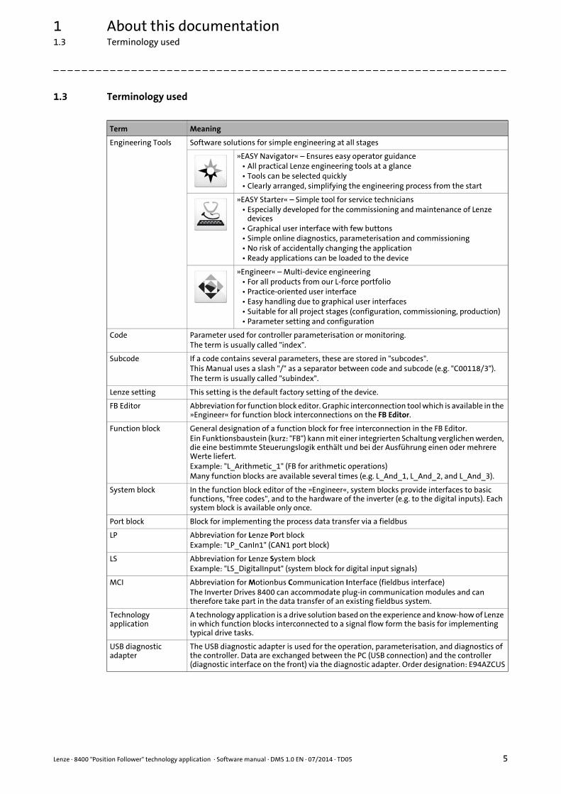
1.3 Terminology used
Term Meaning
Engineering Tools Software solutions for simple engineering at all stages
»EASY Navigator« – Ensures easy operator guidance• All practical Lenze engineering tools at a glance• Tools can be selected quickly• Clearly arranged, simplifying the engineering process from the start
»EASY Starter« – Simple tool for service technicians• Especially developed for the commissioning and maintenance of Lenze
devices• Graphical user interface with few buttons• Simple online diagnostics, parameterisation and commissioning• No risk of accidentally changing the application• Ready applications can be loaded to the device
»Engineer« – Multi-device engineering• For all products from our L-force portfolio• Practice-oriented user interface• Easy handling due to graphical user interfaces• Suitable for all project stages (configuration, commissioning, production)• Parameter setting and configuration
Code Parameter used for controller parameterisation or monitoring. The term is usually called "index".
Subcode If a code contains several parameters, these are stored in "subcodes".This Manual uses a slash "/" as a separator between code and subcode (e.g. "C00118/3").The term is usually called "subindex".
Lenze setting This setting is the default factory setting of the device.
FB Editor Abbreviation for function block editor. Graphic interconnection tool which is available in the »Engineer« for function block interconnections on the FB Editor.
Function block General designation of a function block for free interconnection in the FB Editor.Ein Funktionsbaustein (kurz: "FB") kann mit einer integrierten Schaltung verglichen werden, die eine bestimmte Steuerungslogik enthält und bei der Ausführung einen oder mehrere Werte liefert.Example: "L_Arithmetic_1" (FB for arithmetic operations)Many function blocks are available several times (e.g. L_And_1, L_And_2, and L_And_3).
System block In the function block editor of the »Engineer«, system blocks provide interfaces to basic functions, "free codes", and to the hardware of the inverter (e.g. to the digital inputs). Each system block is available only once.
Port block Block for implementing the process data transfer via a fieldbus
LP Abbreviation for Lenze Port blockExample: "LP_CanIn1" (CAN1 port block)
LS Abbreviation for Lenze System blockExample: "LS_DigitalInput" (system block for digital input signals)
MCI Abbreviation for Motionbus Communication Interface (fieldbus interface)The Inverter Drives 8400 can accommodate plug-in communication modules and can therefore take part in the data transfer of an existing fieldbus system.
Technology application
A technology application is a drive solution based on the experience and know-how of Lenze in which function blocks interconnected to a signal flow form the basis for implementing typical drive tasks.
USB diagnostic adapter
The USB diagnostic adapter is used for the operation, parameterisation, and diagnostics of the controller. Data are exchanged between the PC (USB connection) and the controller (diagnostic interface on the front) via the diagnostic adapter. Order designation: E94AZCUS
1 About this documentation1.4 Definition of notes used
6 Lenze · 8400 "Position Follower" technology application · Software manual · DMS 1.0 EN · 07/2014 · TD05
_ _ _ _ _ _ _ _ _ _ _ _ _ _ _ _ _ _ _ _ _ _ _ _ _ _ _ _ _ _ _ _ _ _ _ _ _ _ _ _ _ _ _ _ _ _ _ _ _ _ _ _ _ _ _ _ _ _ _ _ _ _ _ _
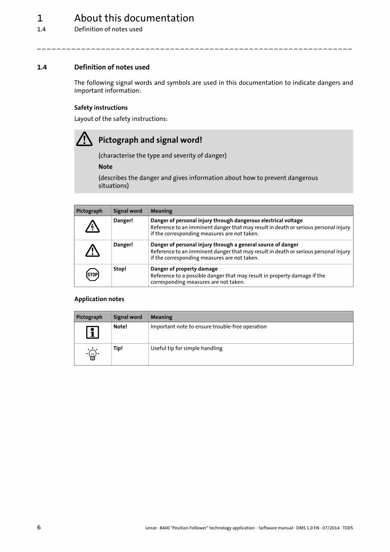
1.4 Definition of notes used
The following signal words and symbols are used in this documentation to indicate dangers andimportant information:
Safety instructions
Layout of the safety instructions:
Application notes
Pictograph and signal word!
(characterise the type and severity of danger)
Note
(describes the danger and gives information about how to prevent dangerous situations)
Pictograph Signal word Meaning
Danger! Danger of personal injury through dangerous electrical voltageReference to an imminent danger that may result in death or serious personal injury if the corresponding measures are not taken.
Danger! Danger of personal injury through a general source of dangerReference to an imminent danger that may result in death or serious personal injury if the corresponding measures are not taken.
Stop! Danger of property damageReference to a possible danger that may result in property damage if the corresponding measures are not taken.
Pictograph Signal word Meaning
Note! Important note to ensure trouble-free operation
Tip! Useful tip for simple handling

Lenze · 8400 "Position Follower" technology application · Software manual · DMS 1.0 EN · 07/2014 · TD05 7
2 Features of the technology application2.1 Functional overview
_ _ _ _ _ _ _ _ _ _ _ _ _ _ _ _ _ _ _ _ _ _ _ _ _ _ _ _ _ _ _ _ _ _ _ _ _ _ _ _ _ _ _ _ _ _ _ _ _ _ _ _ _ _ _ _ _ _ _ _ _ _ _ _
2 Features of the technology application
The "Position Follower" technology application represents a configuration for a slave drive and isused in applications in which one or several 8400 TopLine inverters have to be traversedsynchronously to each other in terms of their position.
The axis bus (X10) is used as transmission medium. If required, a modification to "CAN on board"system bus (X1) or digital frequency coupling (X8) can be effected without high cost. Master valueselection options for the slave position follower ( 27)
The core function comprises a slave drive which follows a master drive with accuracy in terms ofposition. In addition to the "Electrical shaft" function, the application contains a function forpositioning to the master position ("Lock to master") as well as all basic drive functions required(homing, manual jog, position follower, holding brake control).
The "Position Follower" technology application is primarily aimed at master/slave systems withlimited traversing ranges like for example lifting platforms and Gantry axes, since these systemsrequire absolute position synchronism.
Tip!
Each master drive is provided with the "Position Sequencer" and "Electrical Shaft Master"technology applications.
2.1 Functional overview
• Electrical shaft in line topology (all slave drives receive the same master position)
• Transfer of the master position via axis bus
• 1 master drive and up to 61 slave drives
• Adjustable synchronism factor
• "Lock to master" function: automatic straightening of the slave axis when position follower mode is selected
• Superimposition of a position offset with continuous coupling via ramp generator (Y offset)
• Use of the state machine of the Motion Control Kernel (MCK) and the following basic drive functions:• Homing• Manual jog• Position follower• Holding brake control
• Limit position monitoring (hardware limit switches and software limit positions)
• Following error monitoring system
• Control/status signals optionally via digital terminals and fieldbus interface (MCI)
Note!
Systems with modulo measuring systems such as printing units, cross cutters, draw rollers, chain conveyors, etc. are currently not supported by the technology application. Use the "Electrical Shaft Master" and "Electrical Shaft Slave" technology applications for applications of these types.
2 Features of the technology application2.2 Application ranges
8 Lenze · 8400 "Position Follower" technology application · Software manual · DMS 1.0 EN · 07/2014 · TD05
_ _ _ _ _ _ _ _ _ _ _ _ _ _ _ _ _ _ _ _ _ _ _ _ _ _ _ _ _ _ _ _ _ _ _ _ _ _ _ _ _ _ _ _ _ _ _ _ _ _ _ _ _ _ _ _ _ _ _ _ _ _ _ _
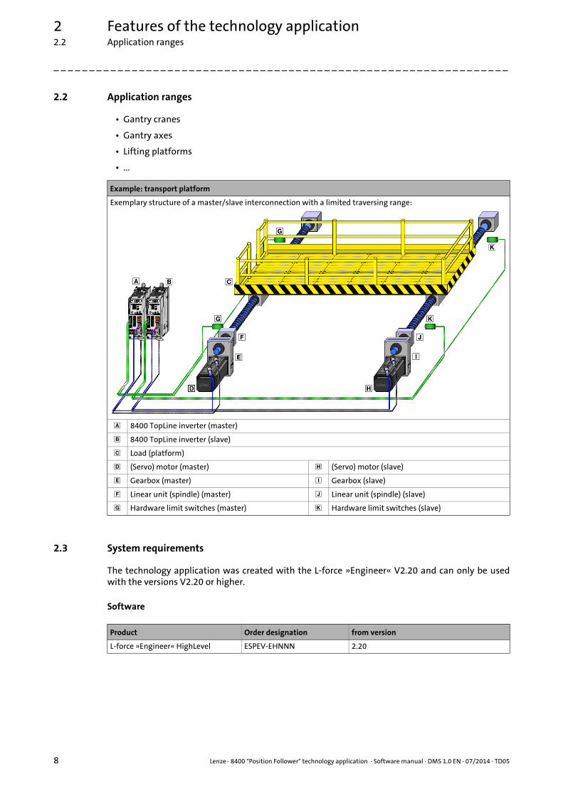
2.2 Application ranges
• Gantry cranes
• Gantry axes
• Lifting platforms
• ...
2.3 System requirements
The technology application was created with the L-force »Engineer« V2.20 and can only be usedwith the versions V2.20 or higher.
Software
Example: transport platform
Exemplary structure of a master/slave interconnection with a limited traversing range:
8400 TopLine inverter (master)
8400 TopLine inverter (slave)
Load (platform)
(Servo) motor (master) (Servo) motor (slave)
Gearbox (master) Gearbox (slave)
Linear unit (spindle) (master) Linear unit (spindle) (slave)
Hardware limit switches (master) Hardware limit switches (slave)
Product Order designation from version
L-force »Engineer« HighLevel ESPEV-EHNNN 2.20
Lenze · 8400 "Position Follower" technology application · Software manual · DMS 1.0 EN · 07/2014 · TD05 9
2 Features of the technology application2.4 Basic signal flow
_ _ _ _ _ _ _ _ _ _ _ _ _ _ _ _ _ _ _ _ _ _ _ _ _ _ _ _ _ _ _ _ _ _ _ _ _ _ _ _ _ _ _ _ _ _ _ _ _ _ _ _ _ _ _ _ _ _ _ _ _ _ _ _
Hardware
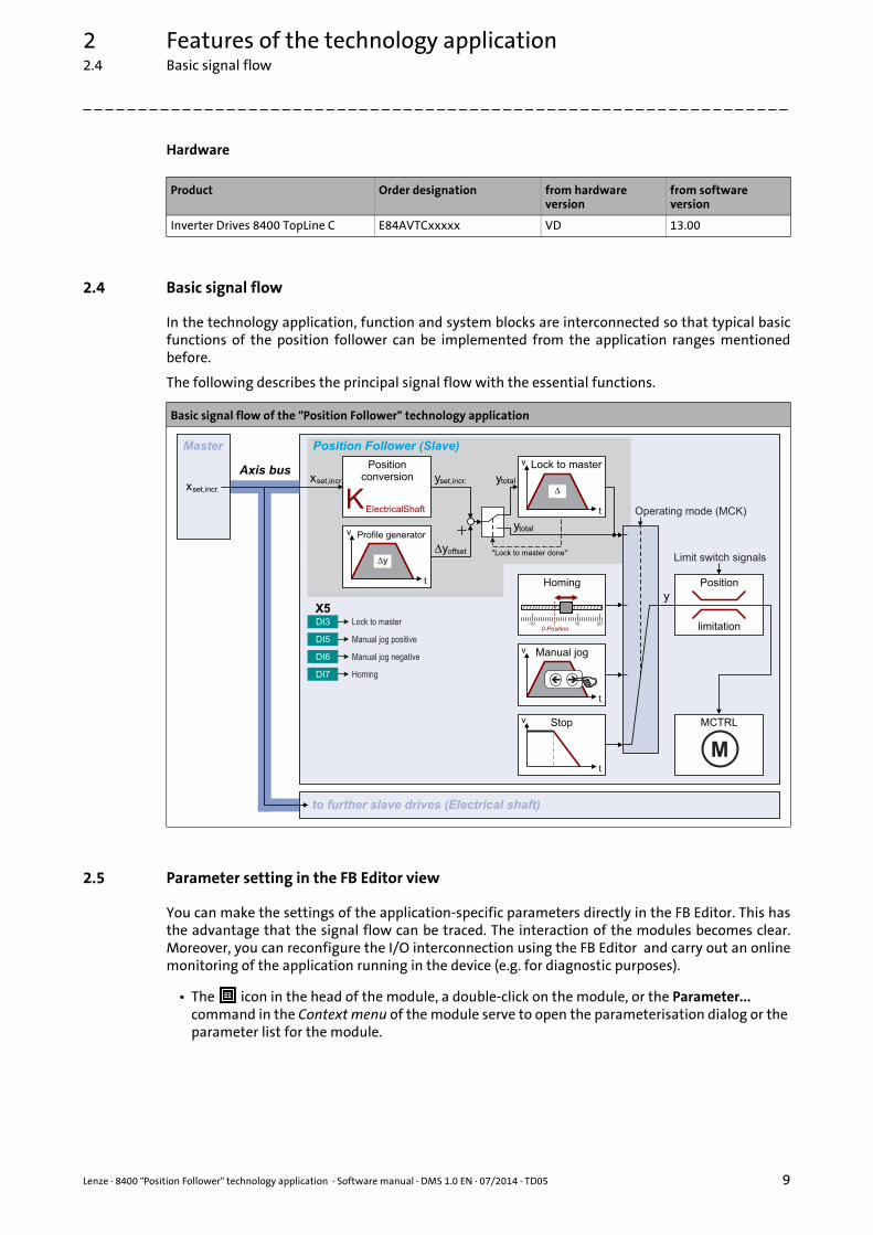
2.4 Basic signal flow
In the technology application, function and system blocks are interconnected so that typical basicfunctions of the position follower can be implemented from the application ranges mentionedbefore.
The following describes the principal signal flow with the essential functions.
2.5 Parameter setting in the FB Editor view
You can make the settings of the application-specific parameters directly in the FB Editor. This hasthe advantage that the signal flow can be traced. The interaction of the modules becomes clear.Moreover, you can reconfigure the I/O interconnection using the FB Editor and carry out an onlinemonitoring of the application running in the device (e.g. for diagnostic purposes).
• The icon in the head of the module, a double-click on the module, or the Parameter... command in the Context menu of the module serve to open the parameterisation dialog or the parameter list for the module.
Product Order designation from hardware version
from software version
Inverter Drives 8400 TopLine C E84AVTCxxxxx VD 13.00
Basic signal flow of the "Position Follower" technology application
Master Position Follower (Slave)
xset,incr.
10 20-10
v
t
v
t
�
Lock to master
v
t
��
KElectricalShaft
v
t
�y
yset,incr.
�yoffset
ytotal
y
xset,incr.
MCTRL
M
"Lock to master done"
ytotal
DI3
DI5
DI6
DI7
X5
Operating mode (MCK)
Axis bus
Homing
Stop
Manual jog
Positionconversion
Profile generator
Position
limitation
Limit switch signals
to further slave drives (Electrical shaft)
Lock to master
Manual jog positive
Manual jog negative
Homing
0-Position
2 Features of the technology application2.5 Parameter setting in the FB Editor view
10 Lenze · 8400 "Position Follower" technology application · Software manual · DMS 1.0 EN · 07/2014 · TD05
_ _ _ _ _ _ _ _ _ _ _ _ _ _ _ _ _ _ _ _ _ _ _ _ _ _ _ _ _ _ _ _ _ _ _ _ _ _ _ _ _ _ _ _ _ _ _ _ _ _ _ _ _ _ _ _ _ _ _ _ _ _ _ _
• Colour codes and comments support you in handling the FB Editor.• The areas highlighted in turquoise represent the "user interface". If required, the pre-
assignment of the I/O terminals can be adapted here and a control via the fieldbus interface (MCI) can be established.
• In the areas highlighted in yellow, application-specific settings are required.
Detailed information on how to work with the FB Editor can be found in the reference manual/online help of the controller in the chapter "Working with the FB Editor".

Lenze · 8400 "Position Follower" technology application · Software manual · DMS 1.0 EN · 07/2014 · TD05 11
2 Features of the technology application2.6 Pre-assignment of the user interface
_ _ _ _ _ _ _ _ _ _ _ _ _ _ _ _ _ _ _ _ _ _ _ _ _ _ _ _ _ _ _ _ _ _ _ _ _ _ _ _ _ _ _ _ _ _ _ _ _ _ _ _ _ _ _ _ _ _ _ _ _ _ _ _
2.6 Pre-assignment of the user interface
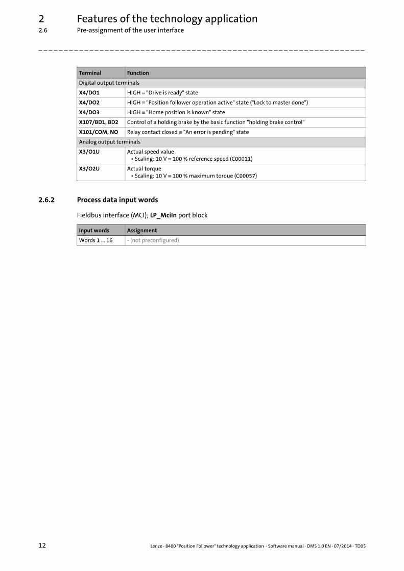
2.6.1 Pre-assignment of the I/O terminals
Terminal Function
Digital input terminals
X5/RFR Controller enable
RFR Function
LOW Inhibit drive
HIGH Enable drive
X5/DI1 - (reserved for HTL encoder)
X5/DI2 - (reserved for HTL encoder)
X5/DI3 Switch on position follower operation ("Lock to master")• Only possible when the controller is enabled and the home position is known.
DI3 Function
LOW The drive unlocks from the electrical shaft and runs to a standstill ("Stop" state) along the stop ramp C01251/1.
HIGH The drive positions to the master position (electrical shaft) and then follows it directly.
Note!The electrical shaft interconnection must only be cancelled at standstill and must be re-established before the drive axes are restarted. Otherwise the system runs askew. Provide for corresponding locking in the higher-level control!
X5/DI4 Connection of pre-switch sensor for reference search• The edge sensitivity of this input and the response to the pre-switch signal depend on the
homing mode selected.
X5/DI5X5/DI6
Manual jog
DI5 DI6 Function
LOW LOW -
HIGH LOW Manual jog in positive direction
LOW HIGH Manual jog in negative direction
HIGH HIGH - / Manual jog in the direction selected first
X5/DI7 Start homing (only possible with controller enable)
DI7 Function
LOW Interrupt/stop homing
LOWHIGH Start homing
Analog input terminals
X3/A1U - (not assigned, can be used freely)
X3/A2U - (not assigned, can be used freely)
2 Features of the technology application2.6 Pre-assignment of the user interface
12 Lenze · 8400 "Position Follower" technology application · Software manual · DMS 1.0 EN · 07/2014 · TD05
_ _ _ _ _ _ _ _ _ _ _ _ _ _ _ _ _ _ _ _ _ _ _ _ _ _ _ _ _ _ _ _ _ _ _ _ _ _ _ _ _ _ _ _ _ _ _ _ _ _ _ _ _ _ _ _ _ _ _ _ _ _ _ _
2.6.2 Process data input words
Fieldbus interface (MCI); LP_MciIn port block
Digital output terminals
X4/DO1 HIGH ≡ "Drive is ready" state
X4/DO2 HIGH ≡ "Position follower operation active" state ("Lock to master done")
X4/DO3 HIGH ≡ "Home position is known" state
X107/BD1, BD2 Control of a holding brake by the basic function "holding brake control"
X101/COM, NO Relay contact closed ≡ "An error is pending" state
Analog output terminals
X3/O1U Actual speed value• Scaling: 10 V ≡ 100 % reference speed (C00011)
X3/O2U Actual torque• Scaling: 10 V ≡ 100 % maximum torque (C00057)
Terminal Function
Input words Assignment
Words 1 ... 16 - (not preconfigured)
Lenze · 8400 "Position Follower" technology application · Software manual · DMS 1.0 EN · 07/2014 · TD05 13
2 Features of the technology application2.6 Pre-assignment of the user interface
_ _ _ _ _ _ _ _ _ _ _ _ _ _ _ _ _ _ _ _ _ _ _ _ _ _ _ _ _ _ _ _ _ _ _ _ _ _ _ _ _ _ _ _ _ _ _ _ _ _ _ _ _ _ _ _ _ _ _ _ _ _ _ _
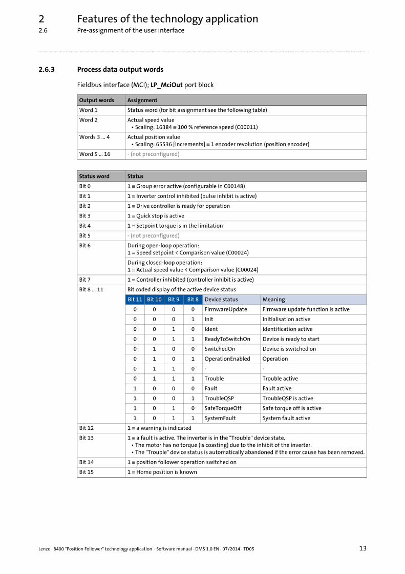
2.6.3 Process data output words
Fieldbus interface (MCI); LP_MciOut port block
Output words Assignment
Word 1 Status word (for bit assignment see the following table)
Word 2 Actual speed value• Scaling: 16384 ≡ 100 % reference speed (C00011)
Words 3 ... 4 Actual position value• Scaling: 65536 [increments] ≡ 1 encoder revolution (position encoder)
Word 5 ... 16 - (not preconfigured)
Status word Status
Bit 0 1 ≡ Group error active (configurable in C00148)
Bit 1 1 ≡ Inverter control inhibited (pulse inhibit is active)
Bit 2 1 ≡ Drive controller is ready for operation
Bit 3 1 ≡ Quick stop is active
Bit 4 1 ≡ Setpoint torque is in the limitation
Bit 5 - (not preconfigured)
Bit 6 During open-loop operation:1 ≡ Speed setpoint < Comparison value (C00024)
During closed-loop operation:1 ≡ Actual speed value < Comparison value (C00024)
Bit 7 1 ≡ Controller inhibited (controller inhibit is active)
Bit 8 ... 11 Bit coded display of the active device status
Bit 11 Bit 10 Bit 9 Bit 8 Device status Meaning
0 0 0 0 FirmwareUpdate Firmware update function is active
0 0 0 1 Init Initialisation active
0 0 1 0 Ident Identification active
0 0 1 1 ReadyToSwitchOn Device is ready to start
0 1 0 0 SwitchedOn Device is switched on
0 1 0 1 OperationEnabled Operation
0 1 1 0 - -
0 1 1 1 Trouble Trouble active
1 0 0 0 Fault Fault active
1 0 0 1 TroubleQSP TroubleQSP is active
1 0 1 0 SafeTorqueOff Safe torque off is active
1 0 1 1 SystemFault System fault active
Bit 12 1 ≡ a warning is indicated
Bit 13 1 ≡ a fault is active. The inverter is in the "Trouble" device state.• The motor has no torque (is coasting) due to the inhibit of the inverter.• The "Trouble" device status is automatically abandoned if the error cause has been removed.
Bit 14 1 ≡ position follower operation switched on
Bit 15 1 ≡ Home position is known
3 Short setup of the technology application3.1 Hardware structure required
14 Lenze · 8400 "Position Follower" technology application · Software manual · DMS 1.0 EN · 07/2014 · TD05
_ _ _ _ _ _ _ _ _ _ _ _ _ _ _ _ _ _ _ _ _ _ _ _ _ _ _ _ _ _ _ _ _ _ _ _ _ _ _ _ _ _ _ _ _ _ _ _ _ _ _ _ _ _ _ _ _ _ _ _ _ _ _ _
3 Short setup of the technology application
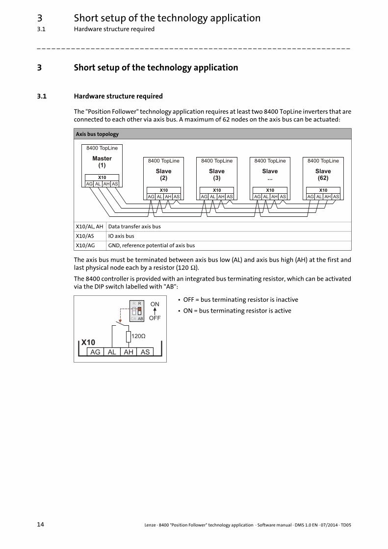
3.1 Hardware structure required
The "Position Follower" technology application requires at least two 8400 TopLine inverters that areconnected to each other via axis bus. A maximum of 62 nodes on the axis bus can be actuated:
The axis bus must be terminated between axis bus low (AL) and axis bus high (AH) at the first andlast physical node each by a resistor (120 Ω).
The 8400 controller is provided with an integrated bus terminating resistor, which can be activatedvia the DIP switch labelled with "AB":
Axis bus topology
X10/AL, AH Data transfer axis bus
X10/AS IO axis bus
X10/AG GND, reference potential of axis bus
• OFF = bus terminating resistor is inactive
• ON = bus terminating resistor is activeR R
CA AB OFF
ON
120Ù
AG AL AH
X10
AS

Lenze · 8400 "Position Follower" technology application · Software manual · DMS 1.0 EN · 07/2014 · TD05 15
3 Short setup of the technology application3.2 Preconditions
_ _ _ _ _ _ _ _ _ _ _ _ _ _ _ _ _ _ _ _ _ _ _ _ _ _ _ _ _ _ _ _ _ _ _ _ _ _ _ _ _ _ _ _ _ _ _ _ _ _ _ _ _ _ _ _ _ _ _ _ _ _ _ _
3.2 Preconditions
For the execution of the short setup described in the following, the setting of the most importantparameters (motor, feedback system, etc.) for each node on the axis bus is assumed.
The "commissioning wizard 8400" serves to carry out a guided commissioning of the controllerbased on the Lenze setting of the parameters.
How to proceed:
1. Before switching on: Make sure that the inverter is inhibited (digitale input terminal X5/RFR open).
2. Switch on voltage supply of the controller.For parameter setting and diagnostics of the controller without motor operation, an external 24-V supply through a safely separated power supply unit (SELV/PELV) is sufficient.
3. Establish a communication link between controller and Engineering PC, e.g. via USB diagnostic adapter (E94AZCUS):• connect the USB diagnostic adapter to the X6 diagnostic interface.• establish a connection between the USB diagnostic adapter and the PC via a free USB port.
4. Start »Engineer« on the Engineering PC, e.g. via the Windows® start menu:Start All programs Lenze Engineering L-force Engineer...After the program start, no project has been loaded first and the start-up wizard is displayed.
5. Create a new project or open a project already available.
6. Go to Project View and select the 8400 controller.
7. Click the icon to go online.After a connection to the controller has been established, the following status is displayed in the Status line:
8. Click the icon to start the commissioning wizard 8400.• Now the commissioning wizard guides you step by step through the setting of the important
parameters for a quick commissioning.• The Next button can only be activated again after all parameter settings in the device have
been reset via the Load Lenze setting button.• Execute the commissioning wizard right to the end.• You can skip the "Control mode" step by clicking Next (only relevant for "Speed actuating
drive" technology application).
You can find detailed information on the options of the start-up wizard and on the general use of the »Engineer« in the online help for the program which you can call with [F1].

3 Short setup of the technology application3.3 Short setup of the master drive
16 Lenze · 8400 "Position Follower" technology application · Software manual · DMS 1.0 EN · 07/2014 · TD05
_ _ _ _ _ _ _ _ _ _ _ _ _ _ _ _ _ _ _ _ _ _ _ _ _ _ _ _ _ _ _ _ _ _ _ _ _ _ _ _ _ _ _ _ _ _ _ _ _ _ _ _ _ _ _ _ _ _ _ _ _ _ _ _
3.3 Short setup of the master drive
Each master drive is provided with the "Position Sequencer" and "Electrical Shaft Master"technology applications.
• With the "Position Sequencer" technology application, the drive can execute parameterisable travel profiles. The program flow is defined on the basis of a sequence table.
• The "Electrical Shaft" technology application serves to easily establish a so-called "electrical shaft" between several 8400 TopLine inverters, so that two or more devices can be used in angular synchronism.
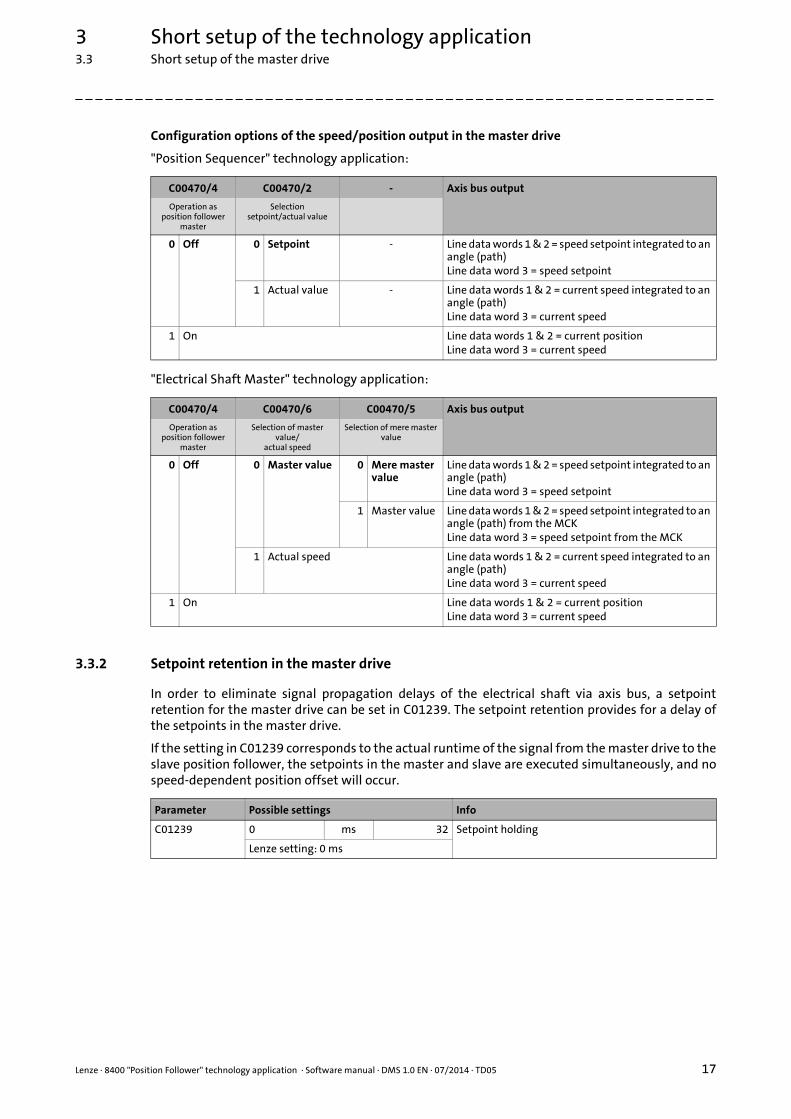
3.3.1 Configuration of the speed/position output in the master drive
For the speed/position output to the slave drives, the LS_AxisBusOut SB is provided in the two"technology applications Position Sequencer" and "Electrical Shaft Master".
• In the default setting, the speed setpoint integrated to an angle (path) is output via line data words 1 & 2, and the speed setpoint is output via line data word 3.
• For optimum interaction with a slave position follower, set the value "1" for the master in C00470/4. Then the current position instead of the integrated speed is output via the axis bus.
Note!
The commissioning process for the master drive is described in the documentation for the corresponding technology application and is not part of this documentation.
The following subchapters only contain notes regarding the commissioning of the master drive.
Stop!
If operation as master position follower is switched on in the master (C00470/4 = "1"), homing of the master causes a step for the slave position follower if the current position is set to the home position!
Remedy: Inhibit the slave position follower when you are referencing the master!
If you are using an individual application in the master drive, provide for a suitable signal interconnection of the LS_AxisBusOut SB!
Lenze · 8400 "Position Follower" technology application · Software manual · DMS 1.0 EN · 07/2014 · TD05 17
3 Short setup of the technology application3.3 Short setup of the master drive
_ _ _ _ _ _ _ _ _ _ _ _ _ _ _ _ _ _ _ _ _ _ _ _ _ _ _ _ _ _ _ _ _ _ _ _ _ _ _ _ _ _ _ _ _ _ _ _ _ _ _ _ _ _ _ _ _ _ _ _ _ _ _ _
Configuration options of the speed/position output in the master drive
"Position Sequencer" technology application:
"Electrical Shaft Master" technology application:
3.3.2 Setpoint retention in the master drive
In order to eliminate signal propagation delays of the electrical shaft via axis bus, a setpointretention for the master drive can be set in C01239. The setpoint retention provides for a delay ofthe setpoints in the master drive.
If the setting in C01239 corresponds to the actual runtime of the signal from the master drive to theslave position follower, the setpoints in the master and slave are executed simultaneously, and nospeed-dependent position offset will occur.
C00470/4 C00470/2 - Axis bus output
Operation as position follower
master
Selectionsetpoint/actual value
0 Off 0 Setpoint - Line data words 1 & 2 = speed setpoint integrated to an angle (path)Line data word 3 = speed setpoint
1 Actual value - Line data words 1 & 2 = current speed integrated to an angle (path)Line data word 3 = current speed
1 On Line data words 1 & 2 = current positionLine data word 3 = current speed
C00470/4 C00470/6 C00470/5 Axis bus output
Operation as position follower
master
Selection of master value/
actual speed
Selection of mere master value
0 Off 0 Master value 0 Mere master value
Line data words 1 & 2 = speed setpoint integrated to an angle (path)Line data word 3 = speed setpoint
1 Master value Line data words 1 & 2 = speed setpoint integrated to an angle (path) from the MCKLine data word 3 = speed setpoint from the MCK
1 Actual speed Line data words 1 & 2 = current speed integrated to an angle (path)Line data word 3 = current speed
1 On Line data words 1 & 2 = current positionLine data word 3 = current speed
Parameter Possible settings Info
C01239 0 ms 32 Setpoint holding
Lenze setting: 0 ms

3 Short setup of the technology application3.4 Short setup of the slave drive
18 Lenze · 8400 "Position Follower" technology application · Software manual · DMS 1.0 EN · 07/2014 · TD05
_ _ _ _ _ _ _ _ _ _ _ _ _ _ _ _ _ _ _ _ _ _ _ _ _ _ _ _ _ _ _ _ _ _ _ _ _ _ _ _ _ _ _ _ _ _ _ _ _ _ _ _ _ _ _ _ _ _ _ _ _ _ _ _
3.4 Short setup of the slave drive
The following steps are to be carried out for all slave position followers of the interconnection.
3.4.1 Step 1: Load "Position Follower" technology application
In the Lenze setting, the inverter uses the "Speed actuating drive" technology application integratedin the device. Execute the following steps to use the "Position Follower" technology applicationinstead:
1. Select the controller in the Project view.
2. If there is still an online connection to the controller:
Click the icon to go offline again.(the application can only be selected offline.)
3. Click the icon to select another application.The Insert application dialog box appears:
4. In the left field, select the "Packages" "Applications" category.
5. In the right field, select the "Position Follower" application.
6. Activate the Except motor data parameters option in order that the settings of the motor data parameters made before will not be overwritten.
7. Press Complete to close the dialog box again and load the selected application into the »Engineer« project.
8. Confirm the prompt on whether the current application is to be replaced by the "Position Follower" application with Yes.

Lenze · 8400 "Position Follower" technology application · Software manual · DMS 1.0 EN · 07/2014 · TD05 19
3 Short setup of the technology application3.4 Short setup of the slave drive
_ _ _ _ _ _ _ _ _ _ _ _ _ _ _ _ _ _ _ _ _ _ _ _ _ _ _ _ _ _ _ _ _ _ _ _ _ _ _ _ _ _ _ _ _ _ _ _ _ _ _ _ _ _ _ _ _ _ _ _ _ _ _ _
3.4.2 Step 2: Axis bus settings
Make the following settings for every slave controller in the network:
• Axis bus address (C02430/1) = "2" ... "62"• Make sure that all controllers connected to the axis bus have different axis bus addresses.
• Sync signal source (C01120) = "2: AxisBusIO"• With this setting, the synchronisation cycle output by the master is used as synchronisation
source. The parameters C01121 ... C01123 for the synchronisation of the internal time base are automatically set to fixed reasonable values to provide for a technically perfect operation of the axis bus!
• Basically, only one source is allowed to synchronise the internal time base.
• Axis bus IO function (C02440/1) = "2: Slave"• This setting serves to define the slave.
3.4.3 Step 3 (optional): Set up control system via the fieldbus interface (MCI)
In the default setting, the application is controlled via the digital input terminals. If functions are tobe controlled via the fieldbus interface (MCI), the user interface (area highlighted in turquoise) hasto be adapted accordingly in the function block editor.
• The assignment of the outputs on the left to the inputs on the right can be changed at will.
• The inputs on the right are permanently linked to functions of the application.
Tip!
Control via the integrated CANopen interface ("CAN on board") can also be attained bymeans of simple interconnection changes. For this purpose, the LP_CanIn port block has tobe inserted in the interconnection and connected to the corresponding inputs of the userinterface.
Note!
For synchronisation of the master and slave, the axis bus IO line is used. The LS_AxisBusIO SB must therefore not be utilised by the user in the application!
3 Short setup of the technology application3.4 Short setup of the slave drive
20 Lenze · 8400 "Position Follower" technology application · Software manual · DMS 1.0 EN · 07/2014 · TD05
_ _ _ _ _ _ _ _ _ _ _ _ _ _ _ _ _ _ _ _ _ _ _ _ _ _ _ _ _ _ _ _ _ _ _ _ _ _ _ _ _ _ _ _ _ _ _ _ _ _ _ _ _ _ _ _ _ _ _ _ _ _ _ _
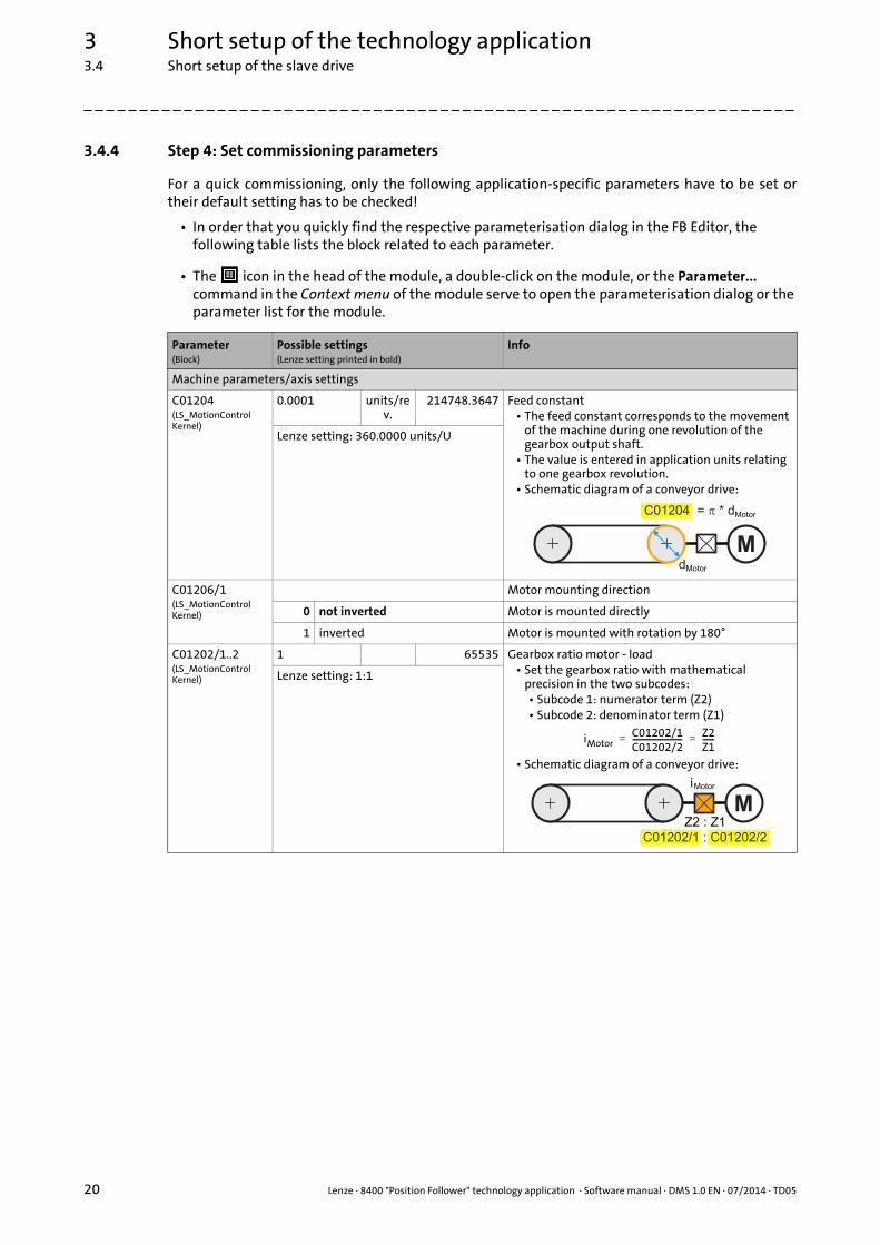
3.4.4 Step 4: Set commissioning parameters
For a quick commissioning, only the following application-specific parameters have to be set ortheir default setting has to be checked!
• In order that you quickly find the respective parameterisation dialog in the FB Editor, the following table lists the block related to each parameter.
• The icon in the head of the module, a double-click on the module, or the Parameter... command in the Context menu of the module serve to open the parameterisation dialog or the parameter list for the module.
Parameter(Block)
Possible settings(Lenze setting printed in bold)
Info
Machine parameters/axis settings
C01204(LS_MotionControlKernel)
0.0001 units/rev.
214748.3647 Feed constant• The feed constant corresponds to the movement
of the machine during one revolution of the gearbox output shaft.
• The value is entered in application units relating to one gearbox revolution.
• Schematic diagram of a conveyor drive:
Lenze setting: 360.0000 units/U
C01206/1(LS_MotionControlKernel)
Motor mounting direction
0 not inverted Motor is mounted directly
1 inverted Motor is mounted with rotation by 180°
C01202/1..2(LS_MotionControlKernel)
1 65535 Gearbox ratio motor - load• Set the gearbox ratio with mathematical
precision in the two subcodes:• Subcode 1: numerator term (Z2)• Subcode 2: denominator term (Z1)
• Schematic diagram of a conveyor drive:
Lenze setting: 1:1
Md
C01204 = * d�
Motor
Motor
iMotorC01202/1C01202/2------------------------- Z2
Z1------= =
M
C01202/1 : C01202/2Z2 : Z1
iMotor
Lenze · 8400 "Position Follower" technology application · Software manual · DMS 1.0 EN · 07/2014 · TD05 21
3 Short setup of the technology application3.4 Short setup of the slave drive
_ _ _ _ _ _ _ _ _ _ _ _ _ _ _ _ _ _ _ _ _ _ _ _ _ _ _ _ _ _ _ _ _ _ _ _ _ _ _ _ _ _ _ _ _ _ _ _ _ _ _ _ _ _ _ _ _ _ _ _ _ _ _ _
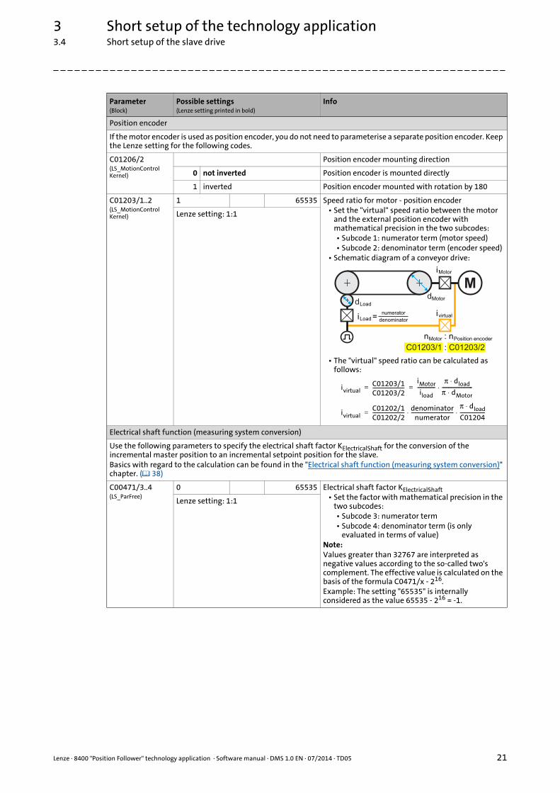
Position encoder
If the motor encoder is used as position encoder, you do not need to parameterise a separate position encoder. Keep the Lenze setting for the following codes.
C01206/2(LS_MotionControlKernel)
Position encoder mounting direction
0 not inverted Position encoder is mounted directly
1 inverted Position encoder mounted with rotation by 180
C01203/1..2(LS_MotionControlKernel)
1 65535 Speed ratio for motor - position encoder• Set the "virtual" speed ratio between the motor
and the external position encoder with mathematical precision in the two subcodes:• Subcode 1: numerator term (motor speed)• Subcode 2: denominator term (encoder speed)
• Schematic diagram of a conveyor drive:
• The "virtual" speed ratio can be calculated as follows:
Lenze setting: 1:1
Electrical shaft function (measuring system conversion)
Use the following parameters to specify the electrical shaft factor KElectricalShaft for the conversion of the incremental master position to an incremental setpoint position for the slave.Basics with regard to the calculation can be found in the "Electrical shaft function (measuring system conversion)" chapter. ( 38)
C00471/3..4(LS_ParFree)
0 65535 Electrical shaft factor KElectricalShaft• Set the factor with mathematical precision in the
two subcodes:• Subcode 3: numerator term• Subcode 4: denominator term (is only
evaluated in terms of value)Note:Values greater than 32767 are interpreted as negative values according to the so-called two's complement. The effective value is calculated on the basis of the formula C0471/x - 216.Example: The setting "65535" is internally considered as the value 65535 - 216 = -1.
Lenze setting: 1:1
Parameter(Block)
Possible settings(Lenze setting printed in bold)
Info
M
C01203/1 : C01203/2
: n
d
iLoadivirtual
iMotor
=numerator
denominator
Load
nMotor Position encoder
dMotor
ivirtualC01203/1C01203/2-------------------------
iMotor
iload--------------
π dload⋅π dMotor⋅------------------------⋅= =
ivirtualC01202/1C01202/2------------------------- denominator
numerator----------------------------------
π dload⋅C01204--------------------⋅ ⋅=
3 Short setup of the technology application3.4 Short setup of the slave drive
22 Lenze · 8400 "Position Follower" technology application · Software manual · DMS 1.0 EN · 07/2014 · TD05
_ _ _ _ _ _ _ _ _ _ _ _ _ _ _ _ _ _ _ _ _ _ _ _ _ _ _ _ _ _ _ _ _ _ _ _ _ _ _ _ _ _ _ _ _ _ _ _ _ _ _ _ _ _ _ _ _ _ _ _ _ _ _ _
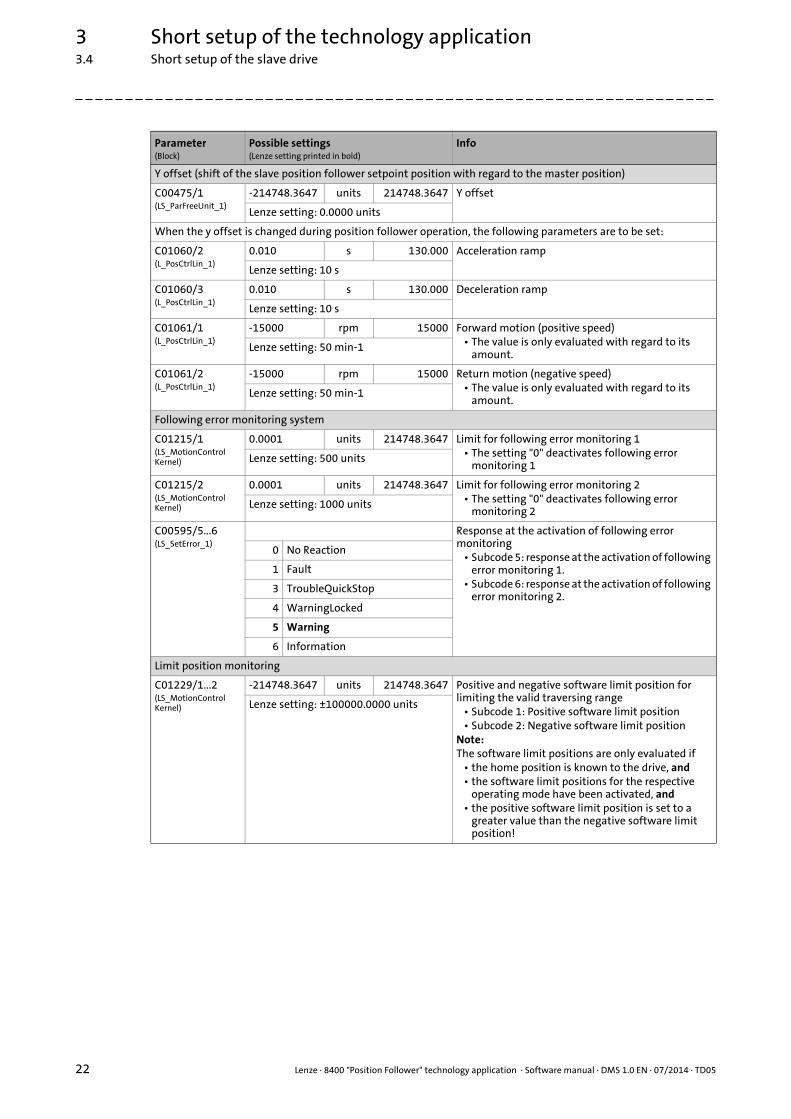
Y offset (shift of the slave position follower setpoint position with regard to the master position)
C00475/1(LS_ParFreeUnit_1)
-214748.3647 units 214748.3647 Y offset
Lenze setting: 0.0000 units
When the y offset is changed during position follower operation, the following parameters are to be set:
C01060/2(L_PosCtrlLin_1)
0.010 s 130.000 Acceleration ramp
Lenze setting: 10 s
C01060/3(L_PosCtrlLin_1)
0.010 s 130.000 Deceleration ramp
Lenze setting: 10 s
C01061/1(L_PosCtrlLin_1)
-15000 rpm 15000 Forward motion (positive speed)• The value is only evaluated with regard to its
amount.Lenze setting: 50 min-1
C01061/2(L_PosCtrlLin_1)
-15000 rpm 15000 Return motion (negative speed)• The value is only evaluated with regard to its
amount.Lenze setting: 50 min-1
Following error monitoring system
C01215/1(LS_MotionControlKernel)
0.0001 units 214748.3647 Limit for following error monitoring 1• The setting "0" deactivates following error
monitoring 1Lenze setting: 500 units
C01215/2(LS_MotionControlKernel)
0.0001 units 214748.3647 Limit for following error monitoring 2• The setting "0" deactivates following error
monitoring 2Lenze setting: 1000 units
C00595/5...6(LS_SetError_1)
Response at the activation of following error monitoring
• Subcode 5: response at the activation of following error monitoring 1.
• Subcode 6: response at the activation of following error monitoring 2.
0 No Reaction
1 Fault
3 TroubleQuickStop
4 WarningLocked
5 Warning
6 Information
Limit position monitoring
C01229/1...2(LS_MotionControlKernel)
-214748.3647 units 214748.3647 Positive and negative software limit position for limiting the valid traversing range
• Subcode 1: Positive software limit position• Subcode 2: Negative software limit position
Note:The software limit positions are only evaluated if
• the home position is known to the drive, and• the software limit positions for the respective
operating mode have been activated, and• the positive software limit position is set to a
greater value than the negative software limit position!
Lenze setting: ±100000.0000 units
Parameter(Block)
Possible settings(Lenze setting printed in bold)
Info

Lenze · 8400 "Position Follower" technology application · Software manual · DMS 1.0 EN · 07/2014 · TD05 23
3 Short setup of the technology application3.4 Short setup of the slave drive
_ _ _ _ _ _ _ _ _ _ _ _ _ _ _ _ _ _ _ _ _ _ _ _ _ _ _ _ _ _ _ _ _ _ _ _ _ _ _ _ _ _ _ _ _ _ _ _ _ _ _ _ _ _ _ _ _ _ _ _ _ _ _ _
3.4.5 Step 5 (optional): Connection of limit switch signals
3.4.6 Step 6: Go online and transfer parameter set to the inverter
In order to set the current parameter settings in the controller to the settings in the project, transmitthe parameter set to the controller.
1. Click the icon to go online.
2. Click the icon to transmit the parameter set to the controller.
3. After a successful transmission, click the icon to save the parameter set safe against mains failure in the integrated memory module.
Note!
In der "Position Follower" technology application, no evaluation of hardware limit switches is prepared by default yet. However, if required, an evaluation can be retrofitted by means of only a few steps.
Limit position monitoring ( 48)
3 Short setup of the technology application3.5 Approaching the drive system (terminal control)
24 Lenze · 8400 "Position Follower" technology application · Software manual · DMS 1.0 EN · 07/2014 · TD05
_ _ _ _ _ _ _ _ _ _ _ _ _ _ _ _ _ _ _ _ _ _ _ _ _ _ _ _ _ _ _ _ _ _ _ _ _ _ _ _ _ _ _ _ _ _ _ _ _ _ _ _ _ _ _ _ _ _ _ _ _ _ _ _
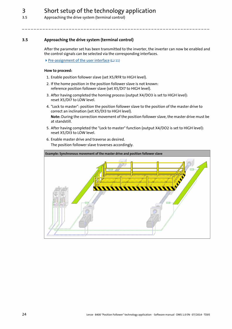
3.5 Approaching the drive system (terminal control)
After the parameter set has been transmitted to the inverter, the inverter can now be enabled andthe control signals can be selected via the corresponding interfaces.
Pre-assignment of the user interface ( 11)
How to proceed:
1. Enable position follower slave (set X5/RFR to HIGH level).
2. If the home position in the position follower slave is not known:reference position follower slave (set X5/DI7 to HIGH level).
3. After having completed the homing process (output X4/DO3 is set to HIGH level):reset X5/DI7 to LOW level.
4. "Lock to master": position the position follower slave to the position of the master drive to correct an inclination (set X5/DI3 to HIGH level).Note: During the correction movement of the position follower slave, the master drive must be at standstill.
5. After having completed the "Lock to master" function (output X4/DO2 is set to HIGH level):reset X5/DI3 to LOW level.
6. Enable master drive and traverse as desired.The position follower slave traverses accordingly.
Example: Synchronous movement of the master drive and position follower slave

Lenze · 8400 "Position Follower" technology application · Software manual · DMS 1.0 EN · 07/2014 · TD05 25
3 Short setup of the technology application3.6 (Optionally): Setting the optimisation parameters in the slave drive
_ _ _ _ _ _ _ _ _ _ _ _ _ _ _ _ _ _ _ _ _ _ _ _ _ _ _ _ _ _ _ _ _ _ _ _ _ _ _ _ _ _ _ _ _ _ _ _ _ _ _ _ _ _ _ _ _ _ _ _ _ _ _ _
3.6 (Optionally): Setting the optimisation parameters in the slave drive
The following application-specific parameters are used for optimisation and can also be adaptedduring operation.
Tip!
Do not forget to save the parameter changes carried out with mains failure protection inthe memory module implemented! (C00002/11 = "1: on/start")
Stop!
If you change parameters in the »Engineer« during an online connection to the device, the changes are directly transferred to the device!
Parameter(Block)
Possible settings Info
Position controller
C00472/1(LS_ParFree_a)
-199.99 % 199.99 Limitation of the position controller output
Lenze setting: 100 % reference speed (C00011)
C00472/2(LS_ParFree_a)
-199.99 % 199.99 Adaptation of the position controller gain
Lenze setting: 100 % Vp (C00254)
Torque limitation in motor mode/in generator mode
The torque limitation set is always active. Example: Definition of the torque limitations
C00472/3(LS_ParFree_a)
-199.99 % 199.99 Torque limitation in motor mode
Lenze setting: 100 % maximum torque (C00057)
C00472/4(LS_ParFree_a)
-199.99 % 199.99 Torque limitation in generator mode
Lenze setting: 100 % maximum torque (C00057)
M
n
50 %
-100 % 100 %50 %
C00472/3 = 25 %
-50 %
25 %
-50 %
-25 %
C00472/4 = 50 %
3 Short setup of the technology application3.6 (Optionally): Setting the optimisation parameters in the slave drive
26 Lenze · 8400 "Position Follower" technology application · Software manual · DMS 1.0 EN · 07/2014 · TD05
_ _ _ _ _ _ _ _ _ _ _ _ _ _ _ _ _ _ _ _ _ _ _ _ _ _ _ _ _ _ _ _ _ _ _ _ _ _ _ _ _ _ _ _ _ _ _ _ _ _ _ _ _ _ _ _ _ _ _ _ _ _ _ _
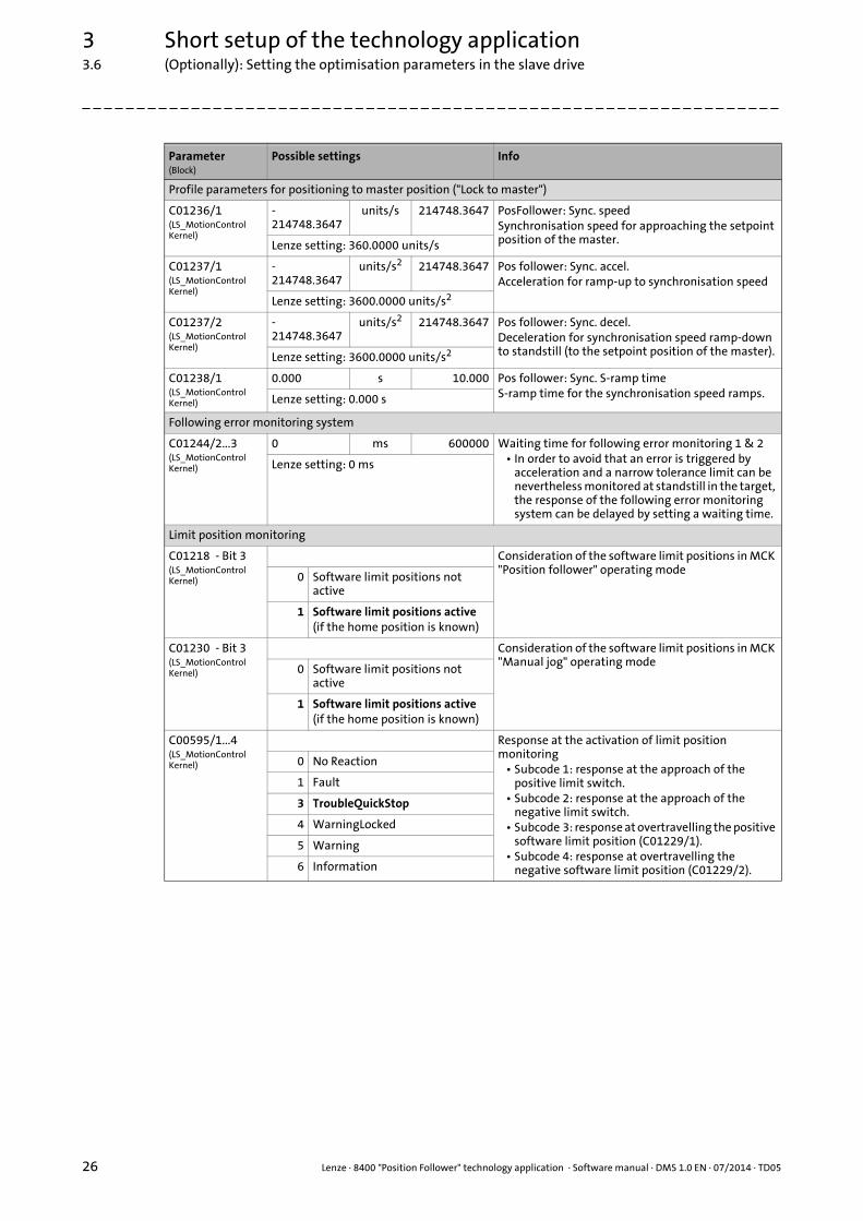
Profile parameters for positioning to master position ("Lock to master")
C01236/1(LS_MotionControlKernel)
-214748.3647
units/s 214748.3647 PosFollower: Sync. speedSynchronisation speed for approaching the setpoint position of the master.Lenze setting: 360.0000 units/s
C01237/1(LS_MotionControlKernel)
-214748.3647
units/s2 214748.3647 Pos follower: Sync. accel.Acceleration for ramp-up to synchronisation speed
Lenze setting: 3600.0000 units/s2
C01237/2(LS_MotionControlKernel)
-214748.3647
units/s2 214748.3647 Pos follower: Sync. decel.Deceleration for synchronisation speed ramp-down to standstill (to the setpoint position of the master).Lenze setting: 3600.0000 units/s2
C01238/1(LS_MotionControlKernel)
0.000 s 10.000 Pos follower: Sync. S-ramp timeS-ramp time for the synchronisation speed ramps.Lenze setting: 0.000 s
Following error monitoring system
C01244/2...3(LS_MotionControlKernel)
0 ms 600000 Waiting time for following error monitoring 1 & 2• In order to avoid that an error is triggered by
acceleration and a narrow tolerance limit can be nevertheless monitored at standstill in the target, the response of the following error monitoring system can be delayed by setting a waiting time.
Lenze setting: 0 ms
Limit position monitoring
C01218 - Bit 3(LS_MotionControlKernel)
Consideration of the software limit positions in MCK "Position follower" operating mode
0 Software limit positions not active
1 Software limit positions active(if the home position is known)
C01230 - Bit 3(LS_MotionControlKernel)
Consideration of the software limit positions in MCK "Manual jog" operating mode
0 Software limit positions not active
1 Software limit positions active(if the home position is known)
C00595/1...4(LS_MotionControlKernel)
Response at the activation of limit position monitoring
• Subcode 1: response at the approach of the positive limit switch.
• Subcode 2: response at the approach of the negative limit switch.
• Subcode 3: response at overtravelling the positive software limit position (C01229/1).
• Subcode 4: response at overtravelling the negative software limit position (C01229/2).
0 No Reaction
1 Fault
3 TroubleQuickStop
4 WarningLocked
5 Warning
6 Information
Parameter(Block)
Possible settings Info
Lenze · 8400 "Position Follower" technology application · Software manual · DMS 1.0 EN · 07/2014 · TD05 27
4 Detailed functions of the technology application4.1 Master value selection options for the slave position follower
_ _ _ _ _ _ _ _ _ _ _ _ _ _ _ _ _ _ _ _ _ _ _ _ _ _ _ _ _ _ _ _ _ _ _ _ _ _ _ _ _ _ _ _ _ _ _ _ _ _ _ _ _ _ _ _ _ _ _ _ _ _ _ _
4 Detailed functions of the technology application
This chapter describes the functions implemented in the "Position Follower" technology applicationwith the possible settings relevant for the application.
4.1 Master value selection options for the slave position follower
The master value for position follower operation can be obtained from different sources:
• Axis bus (X10)
• Digital frequency coupling (X8)
• "CAN on board" system bus (X1)
In the following subchapters, these sources are specified in detail.
4.1.1 Axis bus (X10)
In the default setting, the "Position Follower" technology application uses the master valueselection via the axis bus. In this configuration only an 8400 TopLine can be used as master drive.
Hardware structure required ( 14)
Step 2: Axis bus settings ( 19)
Detailed information on the function and parameterisation of the functions described in the following can be found in the reference manual/online help of the controller.
Note!
Activate the time-out monitoring functions of the axis bus in both the master and the slave drive to prevent the master and slave from moving apart in the case of incorrect master value transmission! Bus monitoring ( 52)
For synchronisation of the master and slave, the axis bus IO line is used. The LS_AxisBusIO SB must therefore not be utilised by the user in the application!

4 Detailed functions of the technology application4.1 Master value selection options for the slave position follower
28 Lenze · 8400 "Position Follower" technology application · Software manual · DMS 1.0 EN · 07/2014 · TD05
_ _ _ _ _ _ _ _ _ _ _ _ _ _ _ _ _ _ _ _ _ _ _ _ _ _ _ _ _ _ _ _ _ _ _ _ _ _ _ _ _ _ _ _ _ _ _ _ _ _ _ _ _ _ _ _ _ _ _ _ _ _ _ _
4.1.2 Digital frequency coupling (X8)
The "Position Follower" technology application can be refitted to a master value selection via digitalfrequency at low cost and effort. Therefore an 8400 TopLine is not absolutely required as masterdrive for the master value selection.
Since the digital frequency signal solely reflects the relative movement of the master (speed signalVElShaft), an integrator (L_PhaseIntK_1) is to be added to the main signal flow, integrating themaster speed (in the example: nActSpeed_v) to a master position:
• The L_PhaseIntK_1 integrator must be called in the processing order before the L_ConvPP_1 FB.
• The integrator must be pre-loaded once with a suitable starting position before position follower operation is started.In the example,• the incremental starting position is preselected via the MCI process data input words 3 + 4.• the starting position is accepted via bit 15 of the application control word
(L_ConvBitsToWord_3 FB). The user must then interconnect this bit accordingly.
Note!
For a master value selection via digital frequency, the multi-encoder interface (X8) must not be occupied by a feedback system!
Example: Retrofitting of the function block interconnection for digital frequency coupling

Lenze · 8400 "Position Follower" technology application · Software manual · DMS 1.0 EN · 07/2014 · TD05 29
4 Detailed functions of the technology application4.1 Master value selection options for the slave position follower
_ _ _ _ _ _ _ _ _ _ _ _ _ _ _ _ _ _ _ _ _ _ _ _ _ _ _ _ _ _ _ _ _ _ _ _ _ _ _ _ _ _ _ _ _ _ _ _ _ _ _ _ _ _ _ _ _ _ _ _ _ _ _ _
4.1.3 "CAN on board" system bus (X1)
The "Position Follower" technology application can be refitted to a master value selection via the"CAN on board" system bus at low cost and effort. Therefore an 8400 TopLine is not absolutelyrequired as master drive for the master value selection.
Compared with the standard signal flow, the signal flow hardly changes at all. Instead of viathe LS_AxisBusIn SB, the master value selection is effected via one of the CAN input ports (in theexample LP_CanIn1):
• The telegram structure must be identical to that for the axis bus: The master position is transferred via CAN process data input words 1 + 2, and the master speed via CAN process data input word 3.
• If transmission cycles > 1 ms are used, the interpolation function (L_Interpolator_1 FB) must be activated and parameterised.
Tip!
In the case of lower to medium demands to the dynamics, even a non-synchronised mastervalue selection can be applied.• For this purpose, the follow-up control contained in the L_Interpolator_1 FB can be used,
which outputs a smoothed speed setpoint at output nNOut.• A downstream integrator (L_PhaseIntK_1) eventually converts the nNOut speed
setpoint to a position setpoint.• By means of the additional logic (L_Not_2), the set position with inactive position
follower operation (L_And_3.bOut = FALSE) is directly loaded to the integrator (L_PhaseIntK_1).
Example: Retrofitting of the function block interconnection for master value selection via CAN
Note!
Compared with the real setpoint, the interpolation produces a dead time which complies with the duration of the interpolation cycles (plus possible transmission times on the data bus). In order to eliminate this dead time, a setpoint retention for the master drive can be set in C01239. Setpoint retention in the master drive ( 17)

4 Detailed functions of the technology application4.2 Basic drive functions (MCK)
30 Lenze · 8400 "Position Follower" technology application · Software manual · DMS 1.0 EN · 07/2014 · TD05
_ _ _ _ _ _ _ _ _ _ _ _ _ _ _ _ _ _ _ _ _ _ _ _ _ _ _ _ _ _ _ _ _ _ _ _ _ _ _ _ _ _ _ _ _ _ _ _ _ _ _ _ _ _ _ _ _ _ _ _ _ _ _ _
4.2 Basic drive functions (MCK)
4.2.1 Operating mode selection
The operating mode selection by the user is carried out in the default setting via the digital inputs.Pre-assignment of the I/O terminals ( 11)
For internal mapping of the individual basic drive functions, the "Position Follower" technologyapplication uses the state machine of the Motion Control Kernel. The desired operating mode isselected via the wOperationMode input of the L_MckCtrlInterface_1 FB.
For a control bit-dependent selection, a corresponding interconnection logic is configured upstreamto the wOperationMode input in the default setting (consisting of the L_DigitalLogic5_1, L_And_1,and L_FixSet_w_1 FBs).
Tip!• C00137 displays the current device state.• C01243 shows the active operating mode of the Motion Control Kernel.
Example: Use of the internal follow-up control in the L_Interpolator_1 with the L_PhaseIntK_1 auxiliary integrator
Danger!
During homing, manual jog, and positioning, specially assigned profile parameters are active. If they have not been set correctly, the drive may carry out an unexpected movement!
Detailed information relating to the basic drive functions and the corresponding parameters can be found in the reference manual/online help of the inverter in the "Basic drive functions (MCK)" chapter.
Note!
If more than one operating mode is selected at the same time, a change-over to the "Stop (STOP)" operating mode is carried out. The drive is braked to a standstill from its movement.

Lenze · 8400 "Position Follower" technology application · Software manual · DMS 1.0 EN · 07/2014 · TD05 31
4 Detailed functions of the technology application4.2 Basic drive functions (MCK)
_ _ _ _ _ _ _ _ _ _ _ _ _ _ _ _ _ _ _ _ _ _ _ _ _ _ _ _ _ _ _ _ _ _ _ _ _ _ _ _ _ _ _ _ _ _ _ _ _ _ _ _ _ _ _ _ _ _ _ _ _ _ _ _
4.2.2 Stop (STOP)
Similar to the 9400 device series, the so-called "Stop" mode is also provided for 8400HighLine/TopLine inverters, braking the drive to a standstill from its movement when a basic drivefunction is deselected.
The "Stop" mode differs from quick stop as follows:
"Stop" is defined as an individual operating mode in the Motion Control Kernel. When anotheroperating mode is deselected, the drive is braked to a standstill from the current movement withthe profile parameters of "Stop". The following setting parameters are provided:
Stop (STOP) Quick stop (QSP)
Is triggered via Motion Control Kernel. Is triggered directly in the motor control. The Motion Control Kernel changes to the "Standby" state immediately.
Deceleration ramp adjustable in C01251/1 in application units [units/s²].
Deceleration ramp adjustable in C00105 in [s] with reference to the reference speed (C00011).
S-ramp time adjustable in C01252/1 in [s]. Only linear ramp.
Braking process is executed in a position-controlled manner.
Braking process is executed in a speed- or position-controlled manner(can be selected via bit 1 in C00104/1).
Standstill is executed in position-controlled manner. Standstill is executed in speed- or position-control(can be selected via bit 0 in C00104/1).
Parameter(Block)
Possible settings Info
C01251/1(LS_MotionControlKernel)
-214748.3647 units/s2 214748.3647 MCK: Stop: Decel.Deceleration for setpoint speed ramp-down to standstill.
Lenze setting: 3600.0000 units/s2
C01251/2(LS_MotionControlKernel)
0.000 s 10.000 MCK: Stop: S-ramp timeS-ramp time for setpoint speed ramp-down to standstill.
Lenze setting: 0.000 s
Stop!
In the case of the 8400 device series, both "Stop" and "Quick stop" (QSP) are executed with the torque that is specified at the LS_MotorInterface SB via the nTorqueMotLimit_a or nTorqueGenLimit_a input (difference to the 9300, ECS, and 9400 device series).
4 Detailed functions of the technology application4.2 Basic drive functions (MCK)
32 Lenze · 8400 "Position Follower" technology application · Software manual · DMS 1.0 EN · 07/2014 · TD05
_ _ _ _ _ _ _ _ _ _ _ _ _ _ _ _ _ _ _ _ _ _ _ _ _ _ _ _ _ _ _ _ _ _ _ _ _ _ _ _ _ _ _ _ _ _ _ _ _ _ _ _ _ _ _ _ _ _ _ _ _ _ _ _
4.2.3 Homing
In order to be able to actuate the drive in a reasonable fashion, the position of the zero positionwithin the physically possible travel range must be known. The zero position, also called the"reference", can be defined by homing or reference setting. This so-called "homing" is usually carriedout after the mains is switched on. Furthermore homing is required after an encoder error has beeneliminated.
• "Manually" starting/stopping the homing process is executed via bit 6 of the application control word (L_ConvBitsToWord_3 FB). In the default setting, bit 6 is linked with digital input DI7.
• Homing is to be configured according to the requirement of the application, as described in the reference manual/online help of the inverter.
• If the home position is known to the drive, a response is sent via digital output DO3 and bit 15 of the MCI process data output word 1.
Note!
Positioning operation and position follower operation can only be executed if the home position is known to the drive (LS_MotionControlKernel.bHomePosAvailable = TRUE). The monitoring of software limit positions can also only be carried out with a known reference!
Note!
The "Position Follower" technology application is typically used on following axes that are coupled to a master axis and further following axes via the mechanics and which can therefore be traversed against each other in any way. Thus the homing processes cannot be executed independently on each axis.
The following procedure has proved of value:• Mount the reference-determining sensors (e.g. touch probe sensor) to the same
position for all axes.• Set the feed constant (C01204) and motor mounting position (C01206/1) on all axes
of the interconnection so that an identical length scaling and counting direction results on all axes.
• Be sure to parameterise all homing profile and position parameters in all axes in an identical manner (see the following parameter list).
• Start the homing process simultaneously on all axes involved and only reset the homing command when all axes in the interconnection have completed the homing process successfully!
Like this, the homing process produces identical traversing profiles for all axes and the mechanics are not pulled askew.
Lenze · 8400 "Position Follower" technology application · Software manual · DMS 1.0 EN · 07/2014 · TD05 33
4 Detailed functions of the technology application4.2 Basic drive functions (MCK)
_ _ _ _ _ _ _ _ _ _ _ _ _ _ _ _ _ _ _ _ _ _ _ _ _ _ _ _ _ _ _ _ _ _ _ _ _ _ _ _ _ _ _ _ _ _ _ _ _ _ _ _ _ _ _ _ _ _ _ _ _ _ _ _
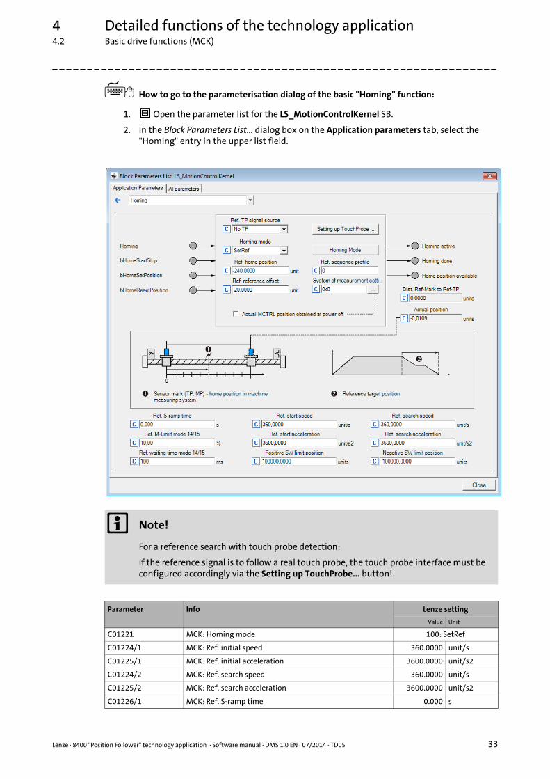
How to go to the parameterisation dialog of the basic "Homing" function:
1. Open the parameter list for the LS_MotionControlKernel SB.
2. In the Block Parameters List... dialog box on the Application parameters tab, select the "Homing" entry in the upper list field.
Note!
For a reference search with touch probe detection:
If the reference signal is to follow a real touch probe, the touch probe interface must be configured accordingly via the Setting up TouchProbe... button!
Parameter Info Lenze setting
Value Unit
C01221 MCK: Homing mode 100: SetRef
C01224/1 MCK: Ref. initial speed 360.0000 unit/s
C01225/1 MCK: Ref. initial acceleration 3600.0000 unit/s2
C01224/2 MCK: Ref. search speed 360.0000 unit/s
C01225/2 MCK: Ref. search acceleration 3600.0000 unit/s2
C01226/1 MCK: Ref. S-ramp time 0.000 s
4 Detailed functions of the technology application4.2 Basic drive functions (MCK)
34 Lenze · 8400 "Position Follower" technology application · Software manual · DMS 1.0 EN · 07/2014 · TD05
_ _ _ _ _ _ _ _ _ _ _ _ _ _ _ _ _ _ _ _ _ _ _ _ _ _ _ _ _ _ _ _ _ _ _ _ _ _ _ _ _ _ _ _ _ _ _ _ _ _ _ _ _ _ _ _ _ _ _ _ _ _ _ _
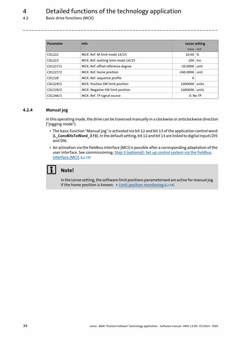
4.2.4 Manual jog
In this operating mode, the drive can be traversed manually in a clockwise or anticlockwise direction("jogging mode").
• The basic function "Manual jog" is activated via bit 12 and bit 13 of the application control word (L_ConvBitsToWord_3 FB). In the default setting, bit 12 and bit 13 are linked to digital inputs DI5 and DI6.
• An activation via the fieldbus interface (MCI) is possible after a corresponding adaptation of the user interface. See commissioning; Step 3 (optional): Set up control system via the fieldbus interface (MCI). ( 19)
C01222 MCK: Ref. M limit mode 14/15 10.00 %
C01223 MCK: Ref. waiting time mode 14/15 100 ms
C01227/1 MCK: Ref. offset reference degree -20.0000 unit
C01227/2 MCK: Ref. home position -240.0000 unit
C01228 MCK: Ref. sequence profile 0
C01229/1 MCK: Positive SW limit position 1000000 units
C01229/2 MCK: Negative SW limit position 1000000 units
C01246/1 MCK: Ref. TP signal source 0: No TP
Parameter Info Lenze setting
Value Unit
Note!
In the Lenze setting, the software limit positions parameterised are active for manual jog if the home position is known. Limit position monitoring ( 48)
Lenze · 8400 "Position Follower" technology application · Software manual · DMS 1.0 EN · 07/2014 · TD05 35
4 Detailed functions of the technology application4.2 Basic drive functions (MCK)
_ _ _ _ _ _ _ _ _ _ _ _ _ _ _ _ _ _ _ _ _ _ _ _ _ _ _ _ _ _ _ _ _ _ _ _ _ _ _ _ _ _ _ _ _ _ _ _ _ _ _ _ _ _ _ _ _ _ _ _ _ _ _ _
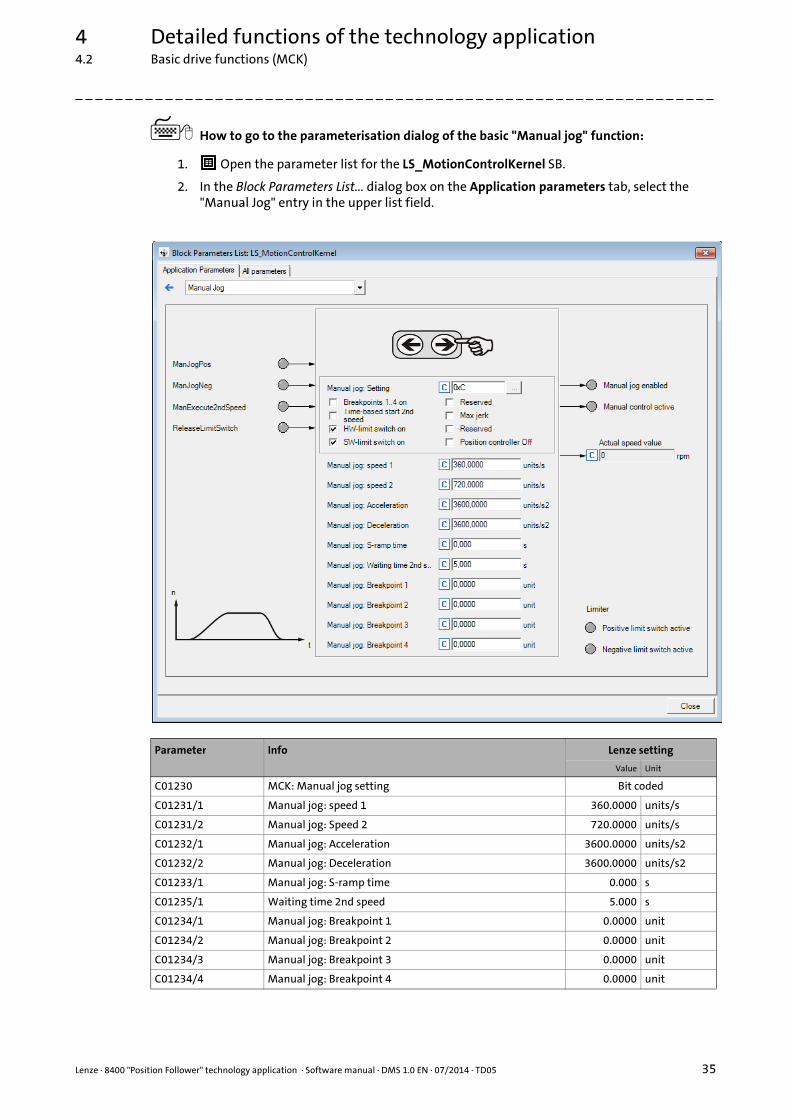
How to go to the parameterisation dialog of the basic "Manual jog" function:
1. Open the parameter list for the LS_MotionControlKernel SB.
2. In the Block Parameters List... dialog box on the Application parameters tab, select the "Manual Jog" entry in the upper list field.
Parameter Info Lenze setting
Value Unit
C01230 MCK: Manual jog setting Bit coded
C01231/1 Manual jog: speed 1 360.0000 units/s
C01231/2 Manual jog: Speed 2 720.0000 units/s
C01232/1 Manual jog: Acceleration 3600.0000 units/s2
C01232/2 Manual jog: Deceleration 3600.0000 units/s2
C01233/1 Manual jog: S-ramp time 0.000 s
C01235/1 Waiting time 2nd speed 5.000 s
C01234/1 Manual jog: Breakpoint 1 0.0000 unit
C01234/2 Manual jog: Breakpoint 2 0.0000 unit
C01234/3 Manual jog: Breakpoint 3 0.0000 unit
C01234/4 Manual jog: Breakpoint 4 0.0000 unit
4 Detailed functions of the technology application4.2 Basic drive functions (MCK)
36 Lenze · 8400 "Position Follower" technology application · Software manual · DMS 1.0 EN · 07/2014 · TD05
_ _ _ _ _ _ _ _ _ _ _ _ _ _ _ _ _ _ _ _ _ _ _ _ _ _ _ _ _ _ _ _ _ _ _ _ _ _ _ _ _ _ _ _ _ _ _ _ _ _ _ _ _ _ _ _ _ _ _ _ _ _ _ _
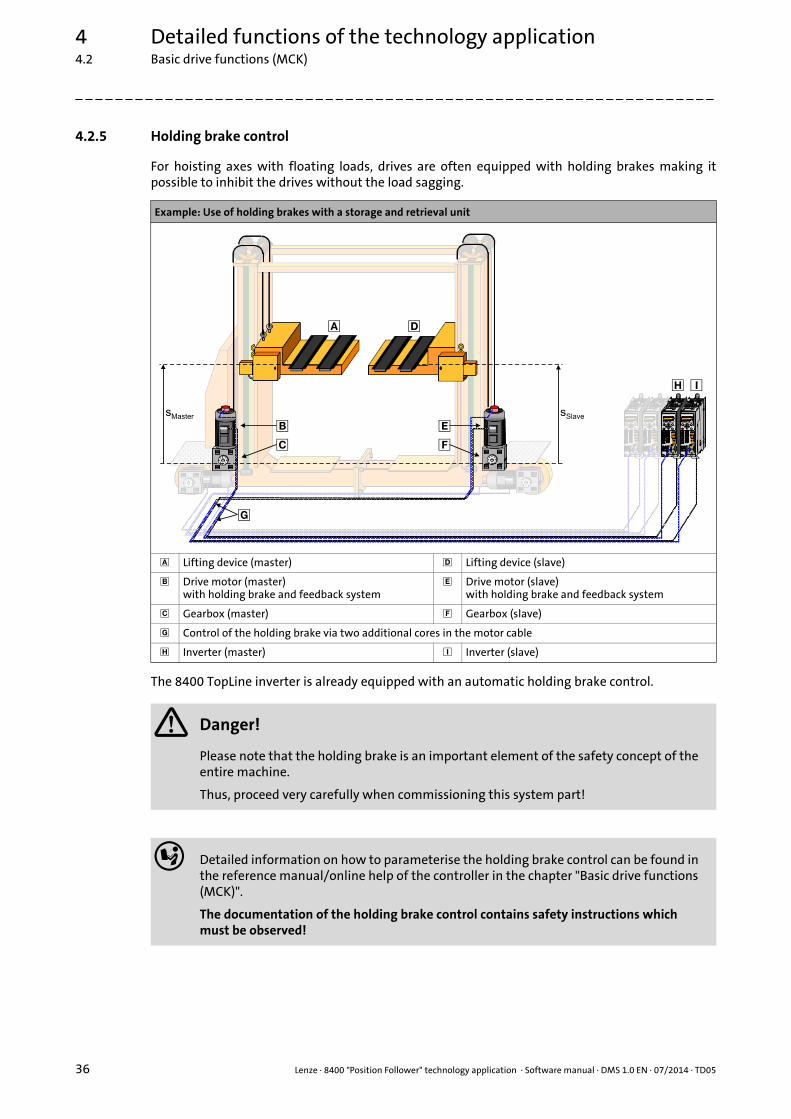
4.2.5 Holding brake control
For hoisting axes with floating loads, drives are often equipped with holding brakes making itpossible to inhibit the drives without the load sagging.
The 8400 TopLine inverter is already equipped with an automatic holding brake control.
Example: Use of holding brakes with a storage and retrieval unit
Lifting device (master) Lifting device (slave)
Drive motor (master)with holding brake and feedback system
Drive motor (slave)with holding brake and feedback system
Gearbox (master) Gearbox (slave)
Control of the holding brake via two additional cores in the motor cable
Inverter (master) Inverter (slave)
Danger!
Please note that the holding brake is an important element of the safety concept of the entire machine.
Thus, proceed very carefully when commissioning this system part!
Detailed information on how to parameterise the holding brake control can be found in the reference manual/online help of the controller in the chapter "Basic drive functions (MCK)".
The documentation of the holding brake control contains safety instructions which must be observed!
sMaster sSlave
� �
�
�
�
�
�
Lenze · 8400 "Position Follower" technology application · Software manual · DMS 1.0 EN · 07/2014 · TD05 37
4 Detailed functions of the technology application4.2 Basic drive functions (MCK)
_ _ _ _ _ _ _ _ _ _ _ _ _ _ _ _ _ _ _ _ _ _ _ _ _ _ _ _ _ _ _ _ _ _ _ _ _ _ _ _ _ _ _ _ _ _ _ _ _ _ _ _ _ _ _ _ _ _ _ _ _ _ _ _
Application-specific notes on the holding brake control:
• In the Lenze setting, the mode 0 (brake control off) is preset in C02580.
• The technology application is prepared for the control of a 24 V holding brake via the high current output (terminal strip X107).
• The application of the holding brake effects a controller inhibit, and with an inhibited inverter, the following error is reset. Starting from version 14.00.00, a following error value can be set in C01215/3, which also remains stored when the controller is inhibited.
• In mode 12 (controlled automatically), the forced release is executed on the holding brake when position follower operation is active ("Lock to master done"), so that the slave drive follows each of the master drive's movements without the holding brake being applied whilst the master value is fixed. For the implementation of this function, the "Lock to master done" signal in the application (L_And_3.bOut) is linked with the bMBrakeRelease input of the LS_MotionControlKernel SB.

4 Detailed functions of the technology application4.3 Position follower functions
38 Lenze · 8400 "Position Follower" technology application · Software manual · DMS 1.0 EN · 07/2014 · TD05
_ _ _ _ _ _ _ _ _ _ _ _ _ _ _ _ _ _ _ _ _ _ _ _ _ _ _ _ _ _ _ _ _ _ _ _ _ _ _ _ _ _ _ _ _ _ _ _ _ _ _ _ _ _ _ _ _ _ _ _ _ _ _ _
4.3 Position follower functions
4.3.1 Electrical shaft function (measuring system conversion)
In order to enable the slave position follower to follow the master in a position-synchronousfashion, the position of the master must be provided in the slave. For this purpose, varioustransmission paths from the master to the slave drive are provided, as described in the "Mastervalue selection options for the slave position follower" chapter.
Then a measuring system conversion is carried out in the slave position follower: The incrementalmaster position xset,incr. is converted to an incremental setpoint position yset,incr. for the slave.
[4-1] Measuring system conversion (excerpt from the basic signal flow)
Master Position Follower (Slave)
v
t
�
Lock to master
KElectricalShaft
v
t
�y"Lock to master done"
MCK
xset,incr. yset,incr. ytotalxset,incr.
ytotal
�yoffset
Axis busMaster to slave
position conversion
Profile generator
Basics for the calculation
Formula for the conversion of the master position to a set position for the slave position follower
Formula for the calculation of the electrical shaft factor KElectricalShaft
Solving for the electrical shaft factor KElectricalShaft from the first formula yields the following:
KElectricalShaft Electrical shaft factor
yset,incr. Incremental set position (y position)
xset,incr. Incremental master position (x position)
iSlave Gearbox ratio of slave position follower
iMaster Gearbox ratio of master drive
FCMaster Feed constant of master drive
FCSlave Feed constant of slave position follower
KUser User proportionality factor (in the case of position synchronism, set to "1"!)
yset,incr. KElectricalShaft xset,incr.⋅iSlave
iMaster----------------
FCMaster
FCSlave--------------------- KUser xset,incr.⋅ ⋅ ⋅= =
KElectricalShaftyset,incr.
xset,incr.-------------------
iSlave
iMaster----------------
FCMaster
FCSlave--------------------- KUser
C00471/3C00471/4-------------------------=⋅ ⋅= =

Lenze · 8400 "Position Follower" technology application · Software manual · DMS 1.0 EN · 07/2014 · TD05 39
4 Detailed functions of the technology application4.3 Position follower functions
_ _ _ _ _ _ _ _ _ _ _ _ _ _ _ _ _ _ _ _ _ _ _ _ _ _ _ _ _ _ _ _ _ _ _ _ _ _ _ _ _ _ _ _ _ _ _ _ _ _ _ _ _ _ _ _ _ _ _ _ _ _ _ _
The electrical shaft factor KElectricalShaft is preselected via the following parameters in the "PositionFollower" technology application:
For the conversion of the position, the L_ConvPP_1 FB is used in the application.
Tip!
Most applications require an exact position synchronism. The user proportionality factorKUser in these cases must always be set to "1".
• With KUser ≠ 1, absolute stretching/compression of the set position, similar to that in the electronic cam technology, can be obtained.
• KUser < 0 produces a movement in the opposite direction with regard to the master.
Parameter(Block)
Possible settings(Lenze setting printed in bold)
Info
C00471/3..4(LS_ParFree)
0 65535 Electrical shaft factor KElectricalShaft• Set the factor with mathematical precision in the
two subcodes:• Subcode 3: numerator term• Subcode 4: denominator term (is only
evaluated in terms of value)Note:Values greater than 32767 are interpreted as negative values according to the so-called two's complement. The effective value is calculated on the basis of the formula C0471/x - 216.Example: The setting "65535" is internally considered as the value 65535 - 216 = -1.
Lenze setting: 1:1
Example: Impact of the user proportionality factor KUser
KUser Impact
1 Position synchronism
>1 Slave travels faster than master
<1 Slave travels slower than master
-1 Slave travels in the opposite direction with regard to the master
0> KUser >1 Slave travels slower than master and in the opposite direction with regard to master
sSlave
sMaster
K = 2User K = 1User
K = 0.5User
K = -0.5UserK = -1User
4 Detailed functions of the technology application4.3 Position follower functions
40 Lenze · 8400 "Position Follower" technology application · Software manual · DMS 1.0 EN · 07/2014 · TD05
_ _ _ _ _ _ _ _ _ _ _ _ _ _ _ _ _ _ _ _ _ _ _ _ _ _ _ _ _ _ _ _ _ _ _ _ _ _ _ _ _ _ _ _ _ _ _ _ _ _ _ _ _ _ _ _ _ _ _ _ _ _ _ _
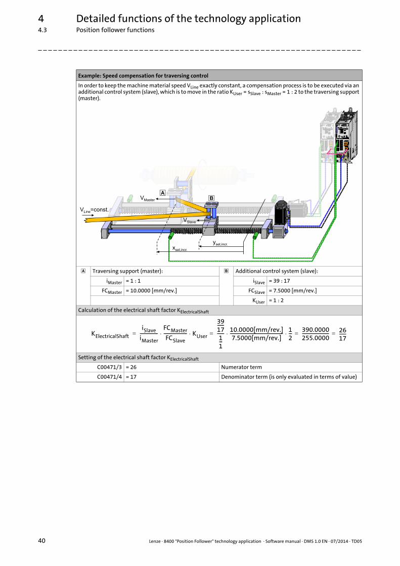
Example: Speed compensation for traversing control
In order to keep the machine material speed VLine exactly constant, a compensation process is to be executed via an additional control system (slave), which is to move in the ratio KUser = sSlave : sMaster = 1 : 2 to the traversing support (master).
Traversing support (master): Additional control system (slave):
iMaster = 1 : 1 iSlave = 39 : 17
FCMaster = 10.0000 [mm/rev.] FCSlave = 7.5000 [mm/rev.]
KUser = 1 : 2
Calculation of the electrical shaft factor KElectricalShaft
Setting of the electrical shaft factor KElectricalShaft
C00471/3 = 26 Numerator term
C00471/4 = 17 Denominator term (is only evaluated in terms of value)
VMaster
��
VSlave
V =const.Line
yset,incr.xset,incr.
KElectricalShaft
iSlave
iMaster----------------
FCMaster
FCSlave--------------------- KUser
3917------
11---
------ 10.0000[mm/rev.]7.5000[mm/rev.]----------------------------------------------- 1
2---
390.0000255.0000------------------------ 26
17------==⋅ ⋅=⋅ ⋅=

Lenze · 8400 "Position Follower" technology application · Software manual · DMS 1.0 EN · 07/2014 · TD05 41
4 Detailed functions of the technology application4.3 Position follower functions
_ _ _ _ _ _ _ _ _ _ _ _ _ _ _ _ _ _ _ _ _ _ _ _ _ _ _ _ _ _ _ _ _ _ _ _ _ _ _ _ _ _ _ _ _ _ _ _ _ _ _ _ _ _ _ _ _ _ _ _ _ _ _ _
4.3.2 Positioning to master position ("Lock to master")
Before the master/slave interconnection can be reasonably actuated in electrical shaft mode, apotential inclination of the slave drive with regard to the master drive must be corrected. Thiscorrection can be mapped by means of a positioning process. The functionality that is referred to as"Lock to master" here is known by the designation "Lock to cam" from the field of electronic camtechnology.
[4-2] "Lock to master" function (excerpt from the basic signal flow)
In the "Position Follower" technology application, the basic function "position follower" of theMotion Control Kernel (MCK) is used for the correction of the inclination. The correction isautomatically executed if position follower operation is switched on.
• Position follower operation is switched on via bit 9 of the application control word (L_ConvBitsToWord_3 FB). In the default setting, bit 9 is linked with digital input DI3.
• Positioning to the master position can only be executed when the home position is known.
• When positioning to the master position (correction of the inclination) has been completed ("Lock to master done"), feedback is given via digital output DO2 and bit 14 of the MCI process data output word 1.
Master Position Follower (Slave)
v
t
�
Lock to master
KElectricalShaft
v
t
�y"Lock to master done"
MCK
xset,incr. yset,incr. ytotalxset,incr.
ytotal
�yoffset
Axis busMaster to slave
position conversion
Profile generator
Inclination of the slave drive by the difference Δs before switching on the "Position follower" operating mode
Correct position of the slave drive after correction of the inclination Δs ("Lock to master done")
�s
�s
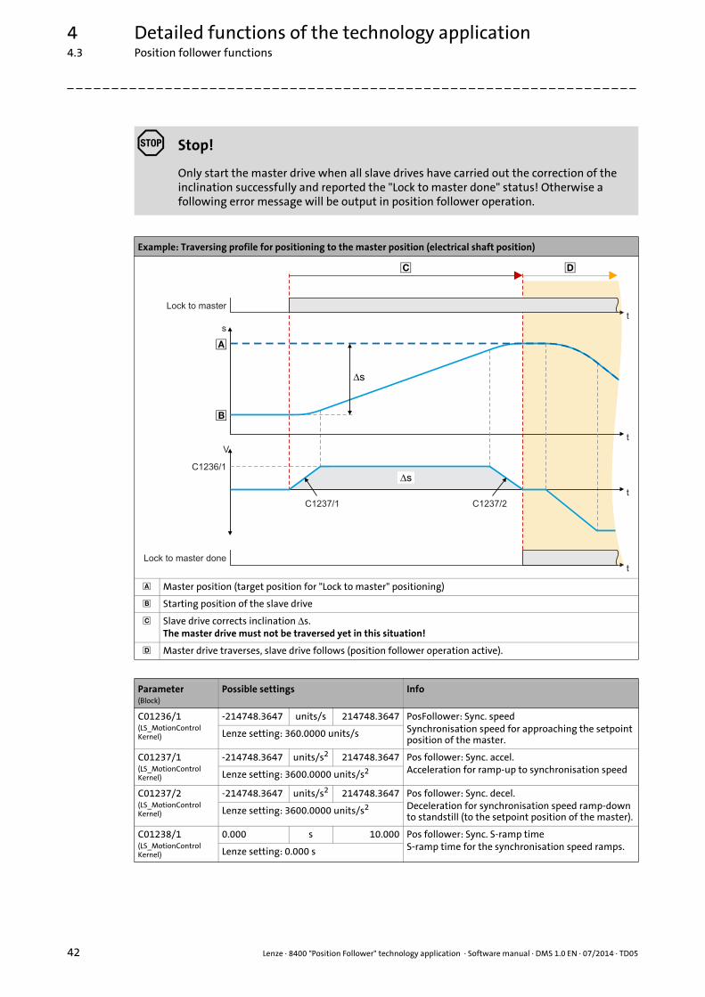
4 Detailed functions of the technology application4.3 Position follower functions
42 Lenze · 8400 "Position Follower" technology application · Software manual · DMS 1.0 EN · 07/2014 · TD05
_ _ _ _ _ _ _ _ _ _ _ _ _ _ _ _ _ _ _ _ _ _ _ _ _ _ _ _ _ _ _ _ _ _ _ _ _ _ _ _ _ _ _ _ _ _ _ _ _ _ _ _ _ _ _ _ _ _ _ _ _ _ _ _
Stop!
Only start the master drive when all slave drives have carried out the correction of the inclination successfully and reported the "Lock to master done" status! Otherwise a following error message will be output in position follower operation.
Example: Traversing profile for positioning to the master position (electrical shaft position)
Master position (target position for "Lock to master" positioning)
Starting position of the slave drive
Slave drive corrects inclination Δs.The master drive must not be traversed yet in this situation!
Master drive traverses, slave drive follows (position follower operation active).
Parameter(Block)
Possible settings Info
C01236/1(LS_MotionControlKernel)
-214748.3647 units/s 214748.3647 PosFollower: Sync. speedSynchronisation speed for approaching the setpoint position of the master.
Lenze setting: 360.0000 units/s
C01237/1(LS_MotionControlKernel)
-214748.3647 units/s2 214748.3647 Pos follower: Sync. accel.Acceleration for ramp-up to synchronisation speedLenze setting: 3600.0000 units/s2
C01237/2(LS_MotionControlKernel)
-214748.3647 units/s2 214748.3647 Pos follower: Sync. decel.Deceleration for synchronisation speed ramp-down to standstill (to the setpoint position of the master).
Lenze setting: 3600.0000 units/s2
C01238/1(LS_MotionControlKernel)
0.000 s 10.000 Pos follower: Sync. S-ramp timeS-ramp time for the synchronisation speed ramps.Lenze setting: 0.000 s
Lock to master
�
Lock to master done
�s
�s
�
�
�
C1236/1
V
s
C1237/1 C1237/2
t
t
t
t

Lenze · 8400 "Position Follower" technology application · Software manual · DMS 1.0 EN · 07/2014 · TD05 43
4 Detailed functions of the technology application4.3 Position follower functions
_ _ _ _ _ _ _ _ _ _ _ _ _ _ _ _ _ _ _ _ _ _ _ _ _ _ _ _ _ _ _ _ _ _ _ _ _ _ _ _ _ _ _ _ _ _ _ _ _ _ _ _ _ _ _ _ _ _ _ _ _ _ _ _
4.3.3 Shifting the set position (y offset)
In addition to stretching/compression the master position, the set position of the slave can beshifted by an offset distance with regard to the master position. In the signal flow, this offsetcouples in dowstream of the electrical shaft function (measuring system conversion), so that this isalso referred to as an y offset.
[4-3] y offset (excerpt from the basic signal flow)
• The y offset (Δy) is selected via C00475/1 in application units.
• The y offset (Δy) is controlled via a profile generator (L_PosCtrlLin_1 FB), in order to provide for constant setpoint characteristics even if the offset is changed in a discontinuous manner. Like this, the y offset can also be changed during position follower operation.
• The overall setpoint ytotal is composed of the electrical shaft setpoint position yset,incr. and the offset value Δyoffset.
• In terms of function, the y offset causes a shift of the slave setpoint position compared with the master position (also see the following illustration).
Master Position Follower (Slave)
v
t
�
Lock to master
KElectricalShaft
v
t
�y"Lock to master done"
MCK
xset,incr. yset,incr. ytotalxset,incr.
ytotal
�yoffset
Axis busMaster to slave
position conversion
Profile generator
Stop!
When the master and slave axis are mechanically coupled to each other (like for example the traversing platform shown in the "Application ranges" chapter), the y offset function in the slave drive must not be used, because otherwise an inclination in the machine mechanics will occur!

4 Detailed functions of the technology application4.3 Position follower functions
44 Lenze · 8400 "Position Follower" technology application · Software manual · DMS 1.0 EN · 07/2014 · TD05
_ _ _ _ _ _ _ _ _ _ _ _ _ _ _ _ _ _ _ _ _ _ _ _ _ _ _ _ _ _ _ _ _ _ _ _ _ _ _ _ _ _ _ _ _ _ _ _ _ _ _ _ _ _ _ _ _ _ _ _ _ _ _ _
Example: Superimposition of the electrical shaft setpoint position with a y offset
Starting position of the master drive
Y offset selection via C00475/1 (possibly abrupt changes in values)
C01061/1
Voffset
Vmaster
Vtotal
Vmaster,max
Vmaster,max
C01061/1
C01061/2
C01060/2C01060/3
C01060/2 C01060/3
s
�yoffset
�yoffset
�
�
ytotal
yset,incr.
�yoffset
t
t
t
t

Lenze · 8400 "Position Follower" technology application · Software manual · DMS 1.0 EN · 07/2014 · TD05 45
4 Detailed functions of the technology application4.3 Position follower functions
_ _ _ _ _ _ _ _ _ _ _ _ _ _ _ _ _ _ _ _ _ _ _ _ _ _ _ _ _ _ _ _ _ _ _ _ _ _ _ _ _ _ _ _ _ _ _ _ _ _ _ _ _ _ _ _ _ _ _ _ _ _ _ _
Parameter(Block)
Possible settings(Lenze setting printed in bold)
Info
Y offset (shift of the slave position follower setpoint position with regard to the master position)
C00475/1(LS_ParFreeUnit_1)
-214748.3647 units 214748.3647 Y offset
Lenze setting: 0.0000 units
When the y offset is changed during position follower operation, the following parameters are to be set:
C01060/2(L_PosCtrlLin_1)
0.010 s 130.000 Acceleration ramp
Lenze setting: 10 s
C01060/3(L_PosCtrlLin_1)
0.010 s 130.000 Deceleration ramp
Lenze setting: 10 s
C01061/1(L_PosCtrlLin_1)
-15000 rpm 15000 Forward motion (positive speed)• The value is only evaluated with regard to its
amount.Lenze setting: 50 min-1
C01061/2(L_PosCtrlLin_1)
-15000 rpm 15000 Return motion (negative speed)• The value is only evaluated with regard to its
amount.Lenze setting: 50 min-1
Example: Shift of the additional guide (slave) for a traversing control
In order to keep the discharge angle of the material ϕout low at the additional guide, the additional guide is to act as far back as possible in the traversing range. This state can be achieved by a correspondingly negative Δyoffset:
Traversing support (master) Additional guide (slave)
Calculation of the overall setpoint for the slave drive
�out
��
yset,incr.
xset,incr.
ytotal�yoffset
ytotal xset,incr. KElectricalShaft Δyoffset yset,incr. Δyoffset+=+⋅=

4 Detailed functions of the technology application4.4 Monitoring functions
46 Lenze · 8400 "Position Follower" technology application · Software manual · DMS 1.0 EN · 07/2014 · TD05
_ _ _ _ _ _ _ _ _ _ _ _ _ _ _ _ _ _ _ _ _ _ _ _ _ _ _ _ _ _ _ _ _ _ _ _ _ _ _ _ _ _ _ _ _ _ _ _ _ _ _ _ _ _ _ _ _ _ _ _ _ _ _ _
4.4 Monitoring functions
4.4.1 Following error monitoring system
The difference between set position and actual position is called the following error. Ideally, thefollowing error should be "0". The set position is created by the internal definition of the traversingprofiles of the Motion Control Kernel. The actual position is created by the integration of the speedsupplied by the position encoder. The following error is always compensated dynamically. If theposition control is adjusted optimally, only a minimum following error occurs which does notincrease continuously.
Certain processes, however, require that a defined limit as a difference between set position andactual position is not exceeded. If it is exceeded, it may have been caused by a mechanical blockingin the machine and the system part is not situated at the position defined at that time. In such acase, it makes sense to activate the "Fault" error response to make the motor torqueless.
In the 8400 TopLine controller, two independent following error monitoring systems can beparameterised:
[4-4] Two-channel following error monitoring system
Parameter(Block)
Possible settings Info
C01215/1(LS_MotionControlKernel)
0.0001 units 214748.3647 Limit for following error monitoring 1• The setting "0" deactivates following error
monitoring 1Lenze setting: 5.0000 units
C01215/2(LS_MotionControlKernel)
0.0001 units 214748.3647 Limit for following error monitoring 2• The setting "0" deactivates following error
monitoring 2Lenze setting: 10.0000 units
C01244/2...3(LS_MotionControlKernel)
0 ms 60000 Waiting time for following error monitoring 1 & 2• In order to avoid that an error is triggered by
acceleration and a narrow tolerance limit can be nevertheless monitored at standstill in the target, the response of the following error monitoring system can be delayed by setting a waiting time.
Lenze setting: 0 ms
C00595/5...6(LS_SetError_1)
Response at the activation of following error monitoring
• Subcode 5: response at the activation of following error monitoring 1.
• Subcode 6: response at the activation of following error monitoring 2.
0 No Reaction
1 Fault
3 TroubleQuickStop
4 WarningLocked
5 Warning
6 Information
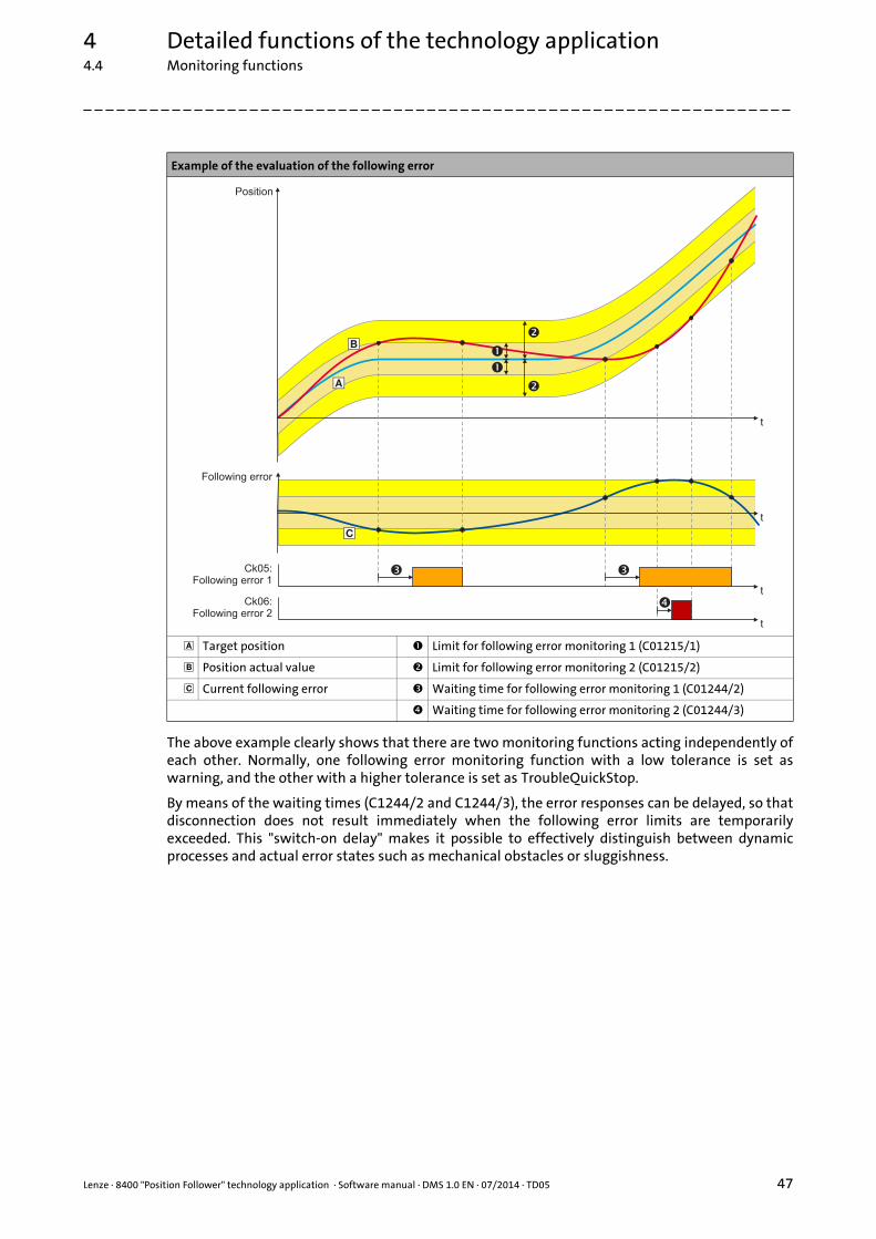
Lenze · 8400 "Position Follower" technology application · Software manual · DMS 1.0 EN · 07/2014 · TD05 47
4 Detailed functions of the technology application4.4 Monitoring functions
_ _ _ _ _ _ _ _ _ _ _ _ _ _ _ _ _ _ _ _ _ _ _ _ _ _ _ _ _ _ _ _ _ _ _ _ _ _ _ _ _ _ _ _ _ _ _ _ _ _ _ _ _ _ _ _ _ _ _ _ _ _ _ _
The above example clearly shows that there are two monitoring functions acting independently ofeach other. Normally, one following error monitoring function with a low tolerance is set aswarning, and the other with a higher tolerance is set as TroubleQuickStop.
By means of the waiting times (C1244/2 and C1244/3), the error responses can be delayed, so thatdisconnection does not result immediately when the following error limits are temporarilyexceeded. This "switch-on delay" makes it possible to effectively distinguish between dynamicprocesses and actual error states such as mechanical obstacles or sluggishness.
Example of the evaluation of the following error
Target position Limit for following error monitoring 1 (C01215/1)
Position actual value Limit for following error monitoring 2 (C01215/2)
Current following error Waiting time for following error monitoring 1 (C01244/2)
Waiting time for following error monitoring 2 (C01244/3)
�
�
�
�
�
t
t
t
t
�
�
�
�
�
Position
Following error
Ck05:1Following error
Ck06:2Following error
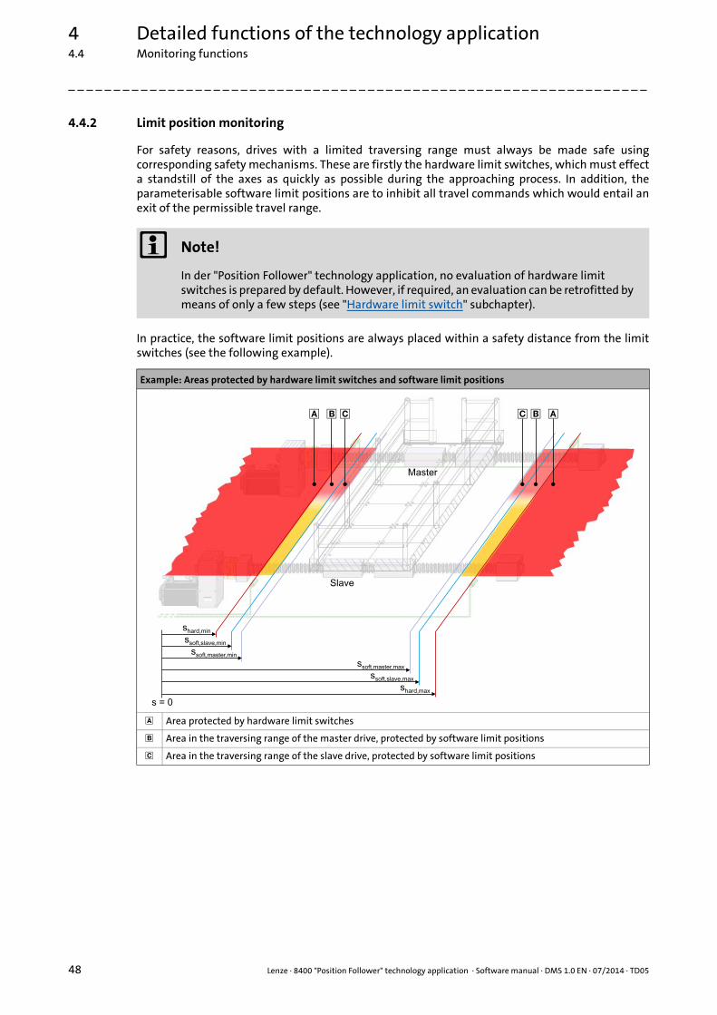
4 Detailed functions of the technology application4.4 Monitoring functions
48 Lenze · 8400 "Position Follower" technology application · Software manual · DMS 1.0 EN · 07/2014 · TD05
_ _ _ _ _ _ _ _ _ _ _ _ _ _ _ _ _ _ _ _ _ _ _ _ _ _ _ _ _ _ _ _ _ _ _ _ _ _ _ _ _ _ _ _ _ _ _ _ _ _ _ _ _ _ _ _ _ _ _ _ _ _ _ _
4.4.2 Limit position monitoring
For safety reasons, drives with a limited traversing range must always be made safe usingcorresponding safety mechanisms. These are firstly the hardware limit switches, which must effecta standstill of the axes as quickly as possible during the approaching process. In addition, theparameterisable software limit positions are to inhibit all travel commands which would entail anexit of the permissible travel range.
In practice, the software limit positions are always placed within a safety distance from the limitswitches (see the following example).
Note!
In der "Position Follower" technology application, no evaluation of hardware limit switches is prepared by default. However, if required, an evaluation can be retrofitted by means of only a few steps (see "Hardware limit switch" subchapter).
Example: Areas protected by hardware limit switches and software limit positions
Area protected by hardware limit switches
Area in the traversing range of the master drive, protected by software limit positions
Area in the traversing range of the slave drive, protected by software limit positions
shard,min
shard,max
ssoft,slave,min
ssoft,slave,max
ssoft,master,min
ssoft,master,max
s = 0
Master
Slave
� � � �� �
Lenze · 8400 "Position Follower" technology application · Software manual · DMS 1.0 EN · 07/2014 · TD05 49
4 Detailed functions of the technology application4.4 Monitoring functions
_ _ _ _ _ _ _ _ _ _ _ _ _ _ _ _ _ _ _ _ _ _ _ _ _ _ _ _ _ _ _ _ _ _ _ _ _ _ _ _ _ _ _ _ _ _ _ _ _ _ _ _ _ _ _ _ _ _ _ _ _ _ _ _
Take the following items into consideration for placing the limit positions:
• The hardware limit switches must be mounted with a sufficient clearance in front of the mechanical limit positions of the linear axis. The clearance to the mechanical limit position should be calculated for a quick stop (QSP) from maximum speed, so that in the event of an error, standstill is attained safely before the mechanical limit position is reached.
• The software limit positions of the slave position follower must be placed with a sufficient distance from the hardware limit switch positions. The distance should be calculated for a quick stop (QSP) from maximum speed without the hardware limit switches being approached.
• The software limit positions of the master must take effect earlier than the software limit positions of the slaves. Like this, error activation by approaching the software limit positions of a slave is prevented.
4.4.2.1 Hardware limit switch
For an evaluation of hardware limit switches, the two digital inputs in the function block editor thatare used for connection of the hardware limit switches have to be connected to the bLimitSwitchNegand bLimitSwitchPos monitoring inputs of the LS_MotionControlKernel system block.
The following example exemplarily shows the connections required if the negative limit switch isconnected to digital input DI1 and the positive limit switch is connected to digital input DI2:
1. LS_DigitalInput.bIn1 LS_MotionControlKernel.bLimitSwitchNeg
2. LS_DigitalInput.bIn2 LS_MotionControlKernel.bLimitSwitchPos
Stop!
The connection of the limit switch signals must be executed in a fail-safe fashion:• LOW level = limit switch approached (activated)• HIGH level = limit switch not approached (not activated)
For this switching logic, the level inversion for the two digital inputs to which the limit switches are connected is to be activated in C00114.(If DI1 and DI2 are used, bit 1 and bit 2 are to be set to "1" in C00114.)
The limit switches are only evaluated if the limit switches for the respective operating mode have been activated (see the following table)!
Operating mode Hardware limit switch effective
Homing Depending on the homing mode selected(see description of the homing modes in the reference manual/online help of the inverter)
Manual jog Yes (adjustable in C01230 - bit 2)
Position follower Yes (adjustable in C01218 - bit 2)
Positioning Yes
4 Detailed functions of the technology application4.4 Monitoring functions
50 Lenze · 8400 "Position Follower" technology application · Software manual · DMS 1.0 EN · 07/2014 · TD05
_ _ _ _ _ _ _ _ _ _ _ _ _ _ _ _ _ _ _ _ _ _ _ _ _ _ _ _ _ _ _ _ _ _ _ _ _ _ _ _ _ _ _ _ _ _ _ _ _ _ _ _ _ _ _ _ _ _ _ _ _ _ _ _
Behaviour when hardware limit switches are active
If one of the two monitoring inputs is set to TRUE, in the Lenze setting the "TroubleQuickStop" errorresponse is triggered: Irrespective of the setpoint selection, the drive is brought to a standstill in thedeceleration time set for the quick stop function. Depending on the error response parameterised,the drive can then only be traversed again after the error has been acknowledged.
4.4.2.2 Software limit positions
The parameterisable limit positions are used by the software to limit the traversing range.
Parameter(Block)
Possible settings Info
C00595/1...2(LS_MotionControlKernel)
Response at the activation of limit position monitoring
• Subcode 1: response at the approach of the positive limit switch.
• Subcode 2: response at the approach of the negative limit switch.
0 No Reaction
1 Fault
3 TroubleQuickStop
4 WarningLocked
5 Warning
6 Information
Note!
Hardware limit switches approached in the case of the 8400 TopLine inverter can only be retracted via the "Manual jog" operating mode.
Stop!
The software limit positions are only evaluated and monitored if the home position is known to the drive and the software limit positions for the respective operating mode have been activated (see following table)!
If the drive is stopped at a high deceleration, depending on the mass inertia and friction, an overvoltage in the DC bus may occur, and pulse inhibit is set as error response. The use of a brake resistor can prevent this response.
Operating mode Software limit positions active (if home position is known)
Homing Yes
Manual jog Yes (adjustable in C01230 - bit 3)
Position follower Yes (adjustable in C01218 - bit 3)
Positioning Yes

Lenze · 8400 "Position Follower" technology application · Software manual · DMS 1.0 EN · 07/2014 · TD05 51
4 Detailed functions of the technology application4.4 Monitoring functions
_ _ _ _ _ _ _ _ _ _ _ _ _ _ _ _ _ _ _ _ _ _ _ _ _ _ _ _ _ _ _ _ _ _ _ _ _ _ _ _ _ _ _ _ _ _ _ _ _ _ _ _ _ _ _ _ _ _ _ _ _ _ _ _
Behaviour in the case of active software limit positions
If the software limit positions are active, travelling commands that would result in the exit from thepermissible travel range can no longer be executed.
If the drive is already outside the permissible travel range and the software limit positions havebeen activated, only travel commands that result in the drive moving back into the permissibletravel range can be executed.
If the software limit positions are active, and one of the software limit positions is overtravelled, inthe Lenze setting the "TroubleQuickStop" error response is triggered: Irrespective of the setpointselection, the drive is brought to a standstill in the deceleration time set for the quick stop function.Depending on the error response parameterised, the drive can then only be traversed again after theerror has been acknowledged.
Parameter(Block)
Possible settings Info
C01229/1...2(LS_MotionControlKernel)
-214748.3647 units 214748.3647 Positive and negative software limit position for limiting the valid traversing range
• Subcode 1: Positive software limit position• Subcode 2: Negative software limit position
Note:The positive software limit position must be set to a greater value than the negative software limit position!
Lenze setting: ±100000.0000 units
C00595/3...4(LS_MotionControlKernel)
Response at the activation of limit position monitoring
• Subcode 3: response at overtravelling the positive software limit position (C01229/1).
• Subcode 4: response at overtravelling the negative software limit position (C01229/2).
0 No Reaction
1 Fault
3 TroubleQuickStop
4 WarningLocked
5 Warning
6 Information
Note!
The "travel commands" mentioned in the following description are no speed setpoint selections. In the "Speed follower" and "Position follower" operating modes, an acknowledged software limit position error ensures that traversing to the impermissible travel range remains possible afterwards. This is because in these two operating modes, there is no preview of whether a software limit position is approached with a setpoint selection.
4 Detailed functions of the technology application4.4 Monitoring functions
52 Lenze · 8400 "Position Follower" technology application · Software manual · DMS 1.0 EN · 07/2014 · TD05
_ _ _ _ _ _ _ _ _ _ _ _ _ _ _ _ _ _ _ _ _ _ _ _ _ _ _ _ _ _ _ _ _ _ _ _ _ _ _ _ _ _ _ _ _ _ _ _ _ _ _ _ _ _ _ _ _ _ _ _ _ _ _ _
4.4.3 Bus monitoring
If an "Electrical shaft" is operated via axis bus, or generally via a bus system, data transmissionerrors, for example due to EMC interference, must always be expected. In order to prevent amechanical offset of the drives in the event of a fault that is only temporary, the L_Interpolator_1FB is used in the slave application. This FB is equipped with an internal correction mechanism,which, in the case of a missing data telegram, provides for an automatic offset correction. Iftransmission cycles > 1 ms are used, the interpolation function must be activated andparameterised.
Parameterisation of the error handling:
Parameter Possible settings Info
C00591/1 Resp. to axis bus data error• Response in the case of an accumulation of data
errors0 No Reaction
1 Fault
2 Trouble
3 TroubleQuickStop
4 WarningLocked
5 Warning
6 Information
C02431/3 0 ms 65000 Axis bus monitoring time• Tolerance time before the data error is triggered• For systems that are coupled in a mechanically
rigid fashion, enter a value that is as small as possible.
Lenze setting: 100 ms

53
Your opinion is important to usThese instructions were created to the best of our knowledge andbelief to give you the best possible support for handling our product.
If you have suggestions for improvement, please e-mail us to:
Thank you for your support.
Your Lenze documentation team
L
8400 "Position Follower" technology application · Software manual · 13467301 · DMS 1.0 EN · 07/2014 · TD05
Lenze Drives GmbHBreslauer Straße 3D-32699 ExtertalGermany
+49 5154 82-0 [email protected] www.lenze.com
ServiceLenze Service GmbHBreslauer Straße 3D-32699 ExtertalGermany
008000 24 46877 (24 h helpline) +49 5154 82-1112 [email protected]