siga-ib detector base installation sheet - home - … r05 siga-ib... · siga-ib detector base...
TRANSCRIPT
© 2013 UTC Fire & Security. All rights reserved. 1 / 4 P/N P-047550-1887 • REV 05 • REB 03APR13
SIGA-IB Detector Base Installation Sheet EN FR
EN: Installation Sheet
Description The SIGA-IB is a detector base with a built-in line fault isolator for use on Class A circuits. It does not operate without a detector and does not support the SIGA-LED Remote LED.
The isolator operates as follows: a short on the line causes all isolators to open within 23 ms; at 10 ms intervals, beginning on the side of the Class A circuit nearest the loop controller, the isolators close to provide the next isolator down the line with power; when the isolator next to the short closes, it reopens within 10 ms. The process repeats beginning on the other side of the loop controller.
Installation
To install the SIGA-IB:
1. Install the electrical box, and bring the field wiring into the box. See Figure 1.
2. Feed the wires through the center hole in the base.
3. Screw the detector base to the electrical box.
4. Connect the field wiring to the terminals on the detector base. Observe polarity. See “Wiring” and Figure 2.
5. Write the address assigned to the detector on the label provided and apply the label to the inside rim of the base.
6. If flush mounting a 4 in. electrical box, use a SIGA-TS Trim Skirt/Ring to give a “finished” appearance to the 4 in. base. Refer to Installation Sheet P/N 387056P for additional information.
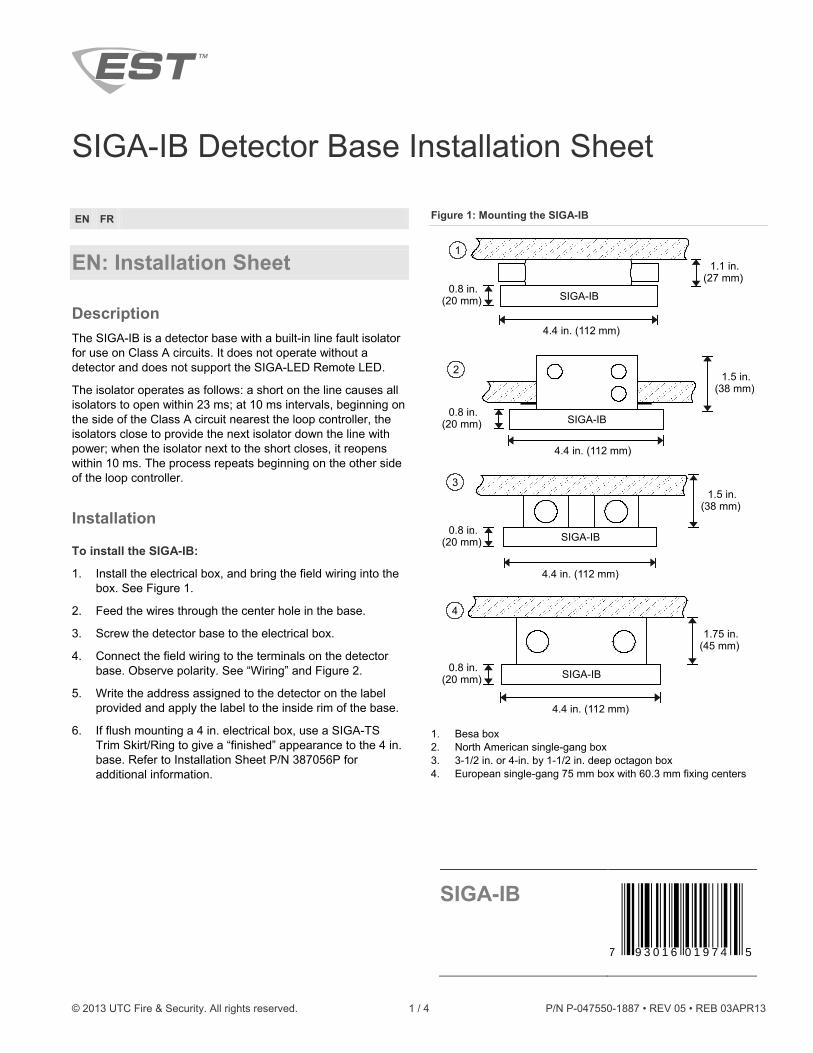
Figure 1: Mounting the SIGA-IB
1. Besa box 2. North American single-gang box 3. 3-1/2 in. or 4-in. by 1-1/2 in. deep octagon box 4. European single-gang 75 mm box with 60.3 mm fixing centers
1.1 in.(27 mm)
0.8 in.(20 mm)
4.4 in. (112 mm)
1
SIGA-IB
1.5 in.(38 mm)
0.8 in.(20 mm)
4.4 in. (112 mm)
2
SIGA-IB
4.4 in. (112 mm)
31.5 in.
(38 mm)
0.8 in.(20 mm)
. SIGA-IB
1.75 in.(45 mm)
0.8 in.(20 mm)
4.4 in. (112 mm)
4
SIGA-IB
SIGA-IB
7 593 016 01 974
2 / 4 P/N P-047550-1887 • REV 05 • REB 03APR13
Wiring
Caution: Electrical supervision requires the wire run to be broken at each terminal. Do not loop the signaling circuit field wires around the terminals.
Notes
• Shielded wire is required only in environments with very high electrical noise.
• Shields, if used, must be continuous and insulated from ground.
• For Class B wiring, there is no shield connection to ground at the last device.
To wire the SIGA-IB:
1. Wire the detector base as shown in Figure 2.
2. Break the wire run at each terminal. Do not loop signaling circuit field wires around terminals.
3. Insulate the shield with electrical tape.
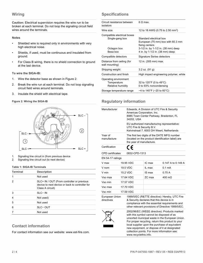
Figure 2: Wiring the SIGA-IB
1. Signaling line circuit in (from previous device 2. Signaling line circuit out (to next device)
Table 1: SIGA-IB Terminals
Terminal Description
1 Not used
2 SLC+ IN / OUT (From controller or previous device to next device or back to controller for Class A circuit)
3 SLC− IN
4 Not used)
5 Not used
6 SLC− OUT
7 Not used
Contact information For contact information see our website: www.est-fire.com.
Specifications Circuit resistance between isolators
6 Ω max.
Wire size 12 to 18 AWG (0.75 to 2.50 mm²)
Compatible electrical boxes Single-gang box Octagon box Besa box
Standard electrical box European (75 mm) box with 60.3 mm fixing centers 3-1/2 in. by 1-1/2 in. (38 mm) deep 4 in. by 1-1/2 in. (38 mm) deep
Compatible detectors Signature Series detectors
Distance from ceiling (for wall mounting)
12 in. (305 mm) max.
Shipping weight 3.2 oz. (91 g)
Construction and finish High impact engineering polymer, white
Operating environment Temperature Relative humidity
32 to 120°F (0 to 49°C) 0 to 93% noncondensing
Storage temperature range −4 to 140°F (−20 to 60°C)
Regulatory information Manufacturer Edwards, A Division of UTC Fire & Security
Americas Corporation, Inc. 8985 Town Center Parkway, Bradenton, FL 34202, USA
EU authorized manufacturing representative: UTC Fire & Security B.V. Kelvinstraat 7, 6003 DH Weert, Netherlands
Year of manufacture
The first two digits of the DATE MFG number (located on the product identification label) are the year of manufacture.
Certification
CPD certificates 0832-CPD-1313
EN 54-17 ratings
V max 19.95 VDC IC max 0.147 A to 0.149 A
V nom 19.0 VDC IL max 0.1 mA
V min 15.2 VDC IS max 0.75 A
Vso max 17.64 VDC ZC max 400 mΩ
Vso min 17.57 VDC
Vsc max 17.70 VDC
Vsc min 17.59 VDC
European Union directives
1999/5/EC (R&TTE directive): Hereby, UTC Fire & Security declares that this device is in compliance with the essential requirements and other relevant provisions of Directive 1999/5/EC.
2002/96/EC (WEEE directive): Products marked with this symbol cannot be disposed of as unsorted municipal waste in the European Union. For proper recycling, return this product to your local supplier upon the purchase of equivalent new equipment, or dispose of it at designated collection points. For more information see: www.recyclethis.info.
2
34
56
7
SLC –
SLC +
SLC –
SLC +
1
2

P/N P-047550-1887 • REV 05 • REB 03APR13 3 / 4
FR: Fiche d’Installation
Description Le SIGA-IB est une base pour détecteur avec un isolateur de défaut de ligne pour une utilisation sur des circuits de classe A. Il ne fonctionne pas sans un détecteur et ne supporte pas le témoin à distance SIGA-LED.
L'isolateur fonctionne comme suit : un court-circuit sur la ligne provoque l'ouverture de tous les isolateurs dans les 23 ms; à intervalles de 10 ms, en commençant sur le circuit le plus près du contrôleur de boucle, les isolateurs à proximité ferment un à un afin d'alimenter l'isolateur suivant, jusqu'à ce que l'isolateur où est situé le cour-circuit se referme. Ce dernier ouvre dans un délai de 10 ms. Le processus se répète à partir de l'autre côté du contrôleur de boucle.
Installation
Pour installer the SIGA-IB :
1. Installez la boîte électrique et introduisez le câblage dans la boîte (voir Figure 1.)
2. Passez les fils dans le trou central dans la base.
3. Vissez la base de détecteur dans la boîte électrique.
4. Reliez le câblage aux bornes sur la base de détecteur. Observez la polarité (voir “Câblage” et Figure 2.)
5. Écrivez l’adresse attribuée au détecteur sur l’étiquette fournie et coller cette dernière sur le bord intérieur de la base.
6. Une jupe de garniture de boîte électrique de 10,16 cm (4 po.) (Réf. SIGA-TS) doit être installée pour donner un aspect final soigné à la base de 10,16 mm. Se référer à la fiche d’installation réf. 387056P pour des renseignements supplémentaires.
Figure 1 : Montage du SIGA-IB
1. Boîte BESA 2. Boîte simple standard 3. Boîte octogonale de 8,89 cm (3,5 po.) ou de10,16cm (4 po.) de
côté de 38 mm (1,5 po.) de profondeur 4. Boîte européenne simple standard de 75 mm, centres de fixation
de 60,3 mm
Câblage
Attention : Interrompre le câblage au niveau de chaque borne. Ne pas enrouler les fils du circuit de signalisation autour des bornes.
Remarques
• Un fil blindé est requis uniquement dans les environnements à interferences électriques élevées.
• Le blindage doit être continu et isolé de la terre.
• Câblage de classe B : aucune connexion n’est effectuée entre le blindage et la terre au niveau du dernier dispositif du circuit.
Boîte européenne simple standard de 75 mm,
27 mm(1,1 po.)
112 mm (4,4 po.)
1
20 mm (0,8 po.) SIGA-IB
38 mm(1,5 po.)
112 mm (4,4 po.)
2
20 mm (0,8 po.) SIGA-IB
112 mm (4,4 po.)
38 mm(1,5 po.)
3
20 mm (0,8 po.) SIGA-IB
45 mm(1,75 po.)
112 mm (4,4 po .)
4
20 mm (0,8 po.) SIGA-IB

4 / 4 P/N P-047550-1887 • REV 05 • REB 03APR13
Pour câbler le SIGA-IB :
1. Câblez la base de détecteur selon la Figure 2.
2. Interrompre le câblage au niveau de chaque borne. Ne pas enrouler les fils du circuit de signalisation autour des bornes.
3. Isoler le blindage avec du ruban adhésif électrique.
Figure 2 : Câblage du SIGA-IB
1. Entrée de la ligne de circuit (SLC) (du dispositif précédent) 2. Sortie de la ligne de circuit (SLC) (au dispositif suivant)
Tableau 1 : Description des bornes
Borne Description
1 Inutilisée
2 SLC + ENTRÉE et SORTIE des lignes de circuit
Du contrôleur ou du dispositif précédent au dispositif suivant ou du retour au contrôleur pour le circuit de Classe A)
3 Entrée de la ligne de circuit SLC −
4 Inutilisée
5 Inutilisée
6 Sortie de la ligne de circuit SLC −
7 Inutilisée
Fiche technique Résistance de circuit entre les isolants
6 Ω max.
Grosseur des fils de l’installation 0.75 à 2.50 mm² (12 à 18 AWG)
Boîtes électriques compatibles| Boîte simple Boîte octogonale Boîte BESA
Boîte standard Boîte européenne 75 mm, centres de fixation de 60,3 mm 8,89 cm (3,5 po.) de côté et 38 mm (1,5 po.) de profondeur 10,16 cm (4 po.) de côté et 38 mm (1,5 po.) de profondeur
Détecteurs compatibles Détecteurs de la série Signature
Distance du plafond (montage mural)
305 mm (12 po.) max.
Poids à la livraison 91 g (3,2 oz.)
Construction et fini Polymère technique avec résistance élevée aux impacts, blanc
Environnement de fonctionnement Température Humidité
−0 à 49°C (32 à 120°F) 0 à 93 % sans condensation
Température de stockage −20 à 60°C (−4 à 140°F)
Référencement des agences Fabricant Edwards, A Division of UTC Fire & Security
Americas Corporation, Inc. 8985 Town Center Parkway, Bradenton, FL 34202, USA
L'Union européenne a autorisé le représentant de fabrication : UTC Fire & Security B.V. Kelvinstraat 7, 6003 DH Weert, Netherlands
Année de fabrication
Les deux premiers chiffres du numéro de MFG DATE (situé sur l'étiquette d'identification de produit) est l'année de fabrication.
Certification
Certificats DPC 0832-CPD-1313
Valeurs EN 54-17
V max 19.95 Vcc IC max 0.147 A to 0.149 A
V nom 19.0 Vcc IL max 0.1 mA
V min 15.2 Vcc IS max 0.75 A
Vso max 17.64 Vcc ZC max 400 mΩ
Vso min 17.57 Vcc
Vsc max 17.70 Vcc
Vsc min 17.59 Vcc
Directives d'Union européenne
1999/5/EC (R&TTE): Par la présente UTC Fire & Security déclare que l'appareil est conforme aux exigences essentielles et aux autres dispositions pertinentes de la directive 1999/5/CE.
2002/96/EC (WEEE): Les produits marqués de ce symbole peuvent pas être éliminés comme déchets municipaux non triés dans l'Union européenne. Pour le recyclage, retourner ce produit à votre fournisseur au moment de l'achat d'un nouvel équipement équivalent, ou à des points de collecte désignés. Pour plus d'informations, voir: www.recyclethis.info.
Coordonnées Coordonnées disponibles sur le site Web : www.est-fire.com.
2
34
56
7
SLC –
SLC +
SLC –
SLC +
1
2