scx800a-3 ci改訂 表1 4
TRANSCRIPT

C�ing S�n!HSC’s updated range of crawler cranes, powered with new-generation clean-operating engines that meet EU Stage V emissions standards. Designed to deliver higher performance to invigorate one and all.
Eco-crane designed for the future.
SCX800A-380 t x 3.3 m
SCX1000A-3100 t x 3.8 m
SCX1800A-3175 t x 4.1 m

Powered with EU Stage V emissions standard-compliant engine,
operating at the cleanest levels possible.
SCX800A-3 / SCX1000A-3 / SCX1800A-3
0.59
■ Clean performance (EU130kW≦560kW)
0.2Stage III A
Stage V 2019~0.17
0.0250.015
0.1
0 432.191 2NOx + HC (g/kWh)
PM (g/kWh)
PM: 0.015 g/kWhPN: 1 x 10¹² g/kWhNOx + HC: 0.59 g/kWh
EUStage V
Stage III BStage IV
Stage V includes newly proposed limits on particle number.
PN: Particulate Number
Engine specificationsEmissions regulationEngine manufacturer/modelDisplacementRated power output EGR SystemExhaust gas aftertreatment device
EU Stage VCummins / QSB6.7
6.7 L210 kW (285 PS) / 2000 min-1
n/aMuffler filter + urea SCR
Coming Soon!Coming Soon!
NEW CLEAN ENGINE
MUFFLER FILTER + UREA SCR
The engine delivers an ideal balance between ultra-low exhaust emissions and superb fuel efficiency, for a crane that fits seamlessly with job sites and the social environment.
Exhaust post-processing systems consist of a muffler filter and urea SCR. The preliminary stage muffler filter reduces PM, while the subsequent stage urea SCR cuts down on NOx emissions. The urea SCR device sprays AdBlue® (urea solution) to decompose NOx into harmless water and nitrogen through chemical reaction.
The new Stage V emissions standards came into effect in the European market from 2019. In addition to standards for existing emissions such as PM and NOx, Stage V also introduces restrictions for the PN (Particulate Number). Even more advanced exhaust post-processing systems are required to meet these toughest emissions standards in the world.
In addition to running cleaner, the system also improves rated power output and medium-range torque of the engine (compared to Stage IV engine specifications).
The exhaust post-processing system features a compact, single-module design for greater performance and ease-of-installation.
The use of a high-capacity urea tank (85 L) helps to enhance convenience.
Enhanced engine performance
Outline of EU Emissions Standards
Exhaust
Single-moduledesign
High-capacityurea tank
Printed in Japan
Address inquiries to :
9-3, Higashi-Ueno 6-chome, Taito-ku, Tokyo 110-0015, JapanPhone: 81-3-3845-1387 Facsimile: 81-3-3845-1394http://www.hsc-cranes.com
2103 01T.EA373
AdBlue® is a registered trademark of the German Association of the Automotive Industry.
DOCDPF
D/MSCR
CleanExhaust

SCX800A-3 Stage IV / Tier 4 f
Printed in Japan2009 05H.EA339
Address inquiries to :
●We are constantly improving our products and therefore reserve the right to change designs and specifications without notice.●Units in this catalog are shown under International System of Units (SI). The figures in parenthesis are under the older British Gravitational System of Units.● Illustrations may include optional equipment and accessories, and may not include all standard equipment.●Standard equipment and accessories may vary by country and region.
Sumitomo Heavy Industries Construction Cranes Co., Ltd. has been abbreviated as “HSC” throughout this catalog. “HSC CRANES” is a brand of Sumitomo Heavy Industries Construction Cranes Co., Ltd.
9-3, Higashi-Ueno 6-chome, Taito-ku, Tokyo 110-0015, JapanPhone: 81-3-3845-1387 Facsimile: 81-3-3845-1394http://www.hsc-cranes.com
■General dimensions Units: mm
■Specifications
SCX800A-3
Model
Application
Max. lifting capacity
Basic boom length
Max. boom length
Crane jib length
Boom + crane jib length
Rope line
speeds (*1)
Swing speed
Travel speed high/low(*2)
Gradeability
Bucket capacity
Allowable gross weight
Max. digging depth
Engine
Ground contact pressure
Operating weight
Front/rear main drum (rated with 7 t load)
3rd winch (rated with 7 t load)
Boom hoist drum
Make & model
Max output
t × m
m
m
m
m
m / min
m / min
m / min
min-1(rpm)
km/h
% ( °)
m3
t
m
kW/min-1 (PS/rpm)
kPa (kgf/cm2)
t
Clamshell
-
9.5
21.5
-
-
105
-
1.2
6.5
36
90 (0.93)w/basic boom, 1.2 m3 bucket
80w/basic boom, 1.2 m3 bucket
Liftcrane
80 x 3.3
9.5
54.5
9~18
45.5 + 18
105 (80)
90 (40)
-
-
-
87 (0.88)w/basic boom, 80 t hook block
76w/basic boom, 80 t hook block
Notes: 1. Rope line speeds vary under load and operating conditions (*1). 2. Travel speed is based on flat, level and firm supporting surface with no load and 9.5 m basic boom (*2).
■Specifications
Support and opening/closing wire rope speed
67
5.0 (5.0)
1.8 / 1.2
30 (17)
Cummins QSB6.7 (Stage / Tier 4 f )
201/2,000 (273/2,000)
SCX800A-3
5500
4000
retracted: 3400(3200)
9500
1100
extended: 4840(4830)
5300(5150)
(178
5)18
75
6280(6060)
5915
470
(380
)
1150
(990
)
810(800)
3200
950
1215
2150
3330
(324
5)
3295 Working Radius
1905
1270
Cast counter weight (opt.)
*( ) is when optional shoes are installed.
R3980
340032
00
Cast counter weight (opt.)

02 03*Photos may differ to the specifications of available products.
SCX800A-3カタログイントロページ P02-03
4mClean engine Compact body Smooth control
Rear endradius less thanEU Stage IV
/ U. S. Tier 4 f
Increasedoperability
New-generation eco-friendly crane
Leading the way to the future, for any type of work, on any worksite.The SCX800A-3 is one of the first models in the industry to meet EU Stage IV/U.S. Tier 4 Final exhaust gas emission regulations, in a quest to develop more eco-friendly operation and work efficiency.Clean performance heralds in a new era of eco-friendly design.Featuring the same compact style that is suited to any location, the SCX800A-3 controls have been fine-tuned immensely for excellent work efficiency and outstanding running costs. A machine that truly revolutionizes any workplace it is operating on.Designed to take your business to new heights; sophistication and maneuverability under your control.
Setting Out for New Heights.
The Good Design Award has been granted to the "SCX-3 Series" for its superb operability, ease of transportation and assembly, safety, and eco-friendly performance as a new generation of crane.

* 80 t class crawler crane
0504
SCX800A-3 PERFORMANCE
OPTION
OPTION
*Photos may differ to the specifications of available products.*The cast counter weight shown here is an optional extra.
SCX800A-3カタログ P4-5
3980 mmSCX800A-3
4300 mmSCX1000A-3
76 t
87 kPa
Total operating weight
Ground contact pressure
Counter weight(piece)
66 t
76 kPa
57 t
65 kPa
(3) (2) (1) (–)
48 t
54 kPa
As a new generation of crane, the goal was to develop operating performance to meet any worksite, and comply with any requirement there. The SCX800A-3 has been designed with even better work efficiency and outstanding mobility. Its optimal power and performance are designed to suit a wide range of worksites, making it even more versatile wherever it goes.
High-performance and compact. Operating capabilities to suit any worksite.
Compact body for tight worksites
The SCX800A-3 has the smallest rear end radius in the 80 t crawler crane class. Powered with the latest clean-running engine, it retains the same compact body size as its predecessor, with a design to suit operations on tight worksites under outstanding levels of safety. Suitable for operating almost anywhere, the SCX800A-3 is engineered to expand on any business opportunity.
The smallest rear end radius in its class* at less than 4 m means it can slot into any worksite!
Rear end radius
Rear end radius (100 t class)
New model winch designed for efficient and stable workBoth the front and rear winches use a new 7 t rated line pull winch (free-fall function is an optional extra). The same 23-winding wide drum that is easy on ropes has been used as with the previous model, with a 37 m line length available in the first winding layer. The drum is designed to prevent ropes tangling when working with the bucket.
Multi-use reduction counter weight specification
Reduction counter weight specifications are available as an optional extra to provide added flexibility for a diverse range of worksites, including platforms and piers where weight restrictions apply (with counter weight detector). Fewer counter weights and a lighter design mean the crane is capable on even more sites.
OPTION
3rd winch
A 3rd winch with free-fall function is available as an optional extra. Featuring the same 7 t rated line pull as the front and rear winches, it comes with a large winding capacity 180 m long rope. This allows the entire casing driver to be hoisted.
Cast counter weights
Cast counter weights that are more compact than the standard type are available as an optional extra. Being made from cast iron, they offer excellent recycling potential.
A 11 t rated line pull winch (rope φ26 mm) is optionally available.
* Figures in the chart above are when the standard counter weight is installed.Note: Reduction counter weight specifications are configured to suit crane specifications excluding the crane jib.
SCX800A-3 CONTROL
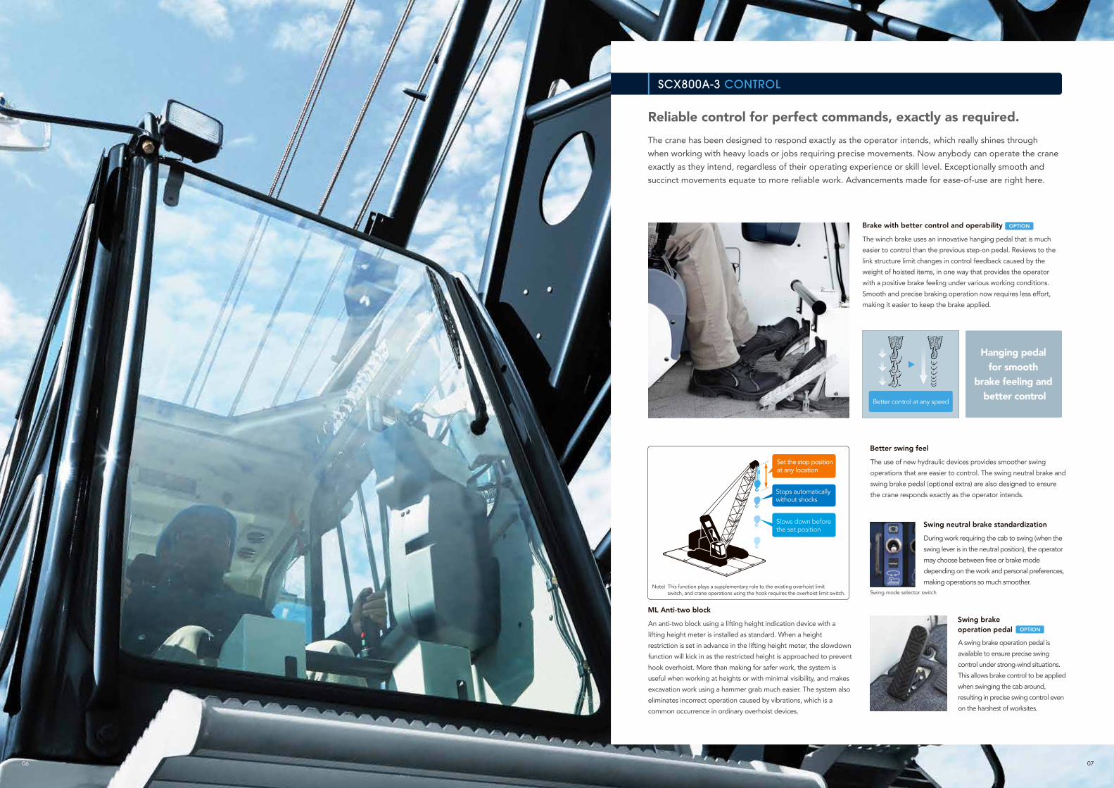
The crane has been designed to respond exactly as the operator intends, which really shines through when working with heavy loads or jobs requiring precise movements. Now anybody can operate the crane exactly as they intend, regardless of their operating experience or skill level. Exceptionally smooth and succinct movements equate to more reliable work. Advancements made for ease-of-use are right here.
Reliable control for perfect commands, exactly as required.
Brake with better control and operability
The winch brake uses an innovative hanging pedal that is much easier to control than the previous step-on pedal. Reviews to the link structure limit changes in control feedback caused by the weight of hoisted items, in one way that provides the operator with a positive brake feeling under various working conditions. Smooth and precise braking operation now requires less effort, making it easier to keep the brake applied.
SCX800A-3カタログ P06-07
06 07
Better control at any speed
Slows down before the set position
Set the stop position at any location
Stops automatically without shocks
Hanging pedal for smooth
brake feeling and better control
ML Anti-two block
An anti-two block using a lifting height indication device with a lifting height meter is installed as standard. When a height restriction is set in advance in the lifting height meter, the slowdown function will kick in as the restricted height is approached to prevent hook overhoist. More than making for safer work, the system is useful when working at heights or with minimal visibility, and makes excavation work using a hammer grab much easier. The system also eliminates incorrect operation caused by vibrations, which is a common occurrence in ordinary overhoist devices.
This function plays a supplementary role to the existing overhoist limit switch, and crane operations using the hook requires the overhoist limit switch. Swing mode selector switch
Note)
Better swing feel
The use of new hydraulic devices provides smoother swing operations that are easier to control. The swing neutral brake and swing brake pedal (optional extra) are also designed to ensure the crane responds exactly as the operator intends.
OPTION
OPTION
Swing neutral brake standardization
During work requiring the cab to swing (when the swing lever is in the neutral position), the operator may choose between free or brake mode depending on the work and personal preferences, making operations so much smoother.
Swing brake operation pedal
A swing brake operation pedal is available to ensure precise swing control under strong-wind situations. This allows brake control to be applied when swinging the cab around, resulting in precise swing control even on the harshest of worksites.

0908
SCX800A-3 SAFETY
1
12
10
4 6
7 98
5
3
2
Maximum lifting height restriction set for the hookActual hook lifting height
1
2
1
2
34
6789105
SCX800A-3カタログ P8-9
The cross operation lever shown here is an optional extra.*Photos may differ to the specifications of available products.
Aftertreatment device displayEngine trouble alarm (yellow)
Engine trouble alarm (red)
DEF/AdBlue® gaugeWarning icons
Moment limiter display
Load ratio indicator (%)
Engine speedLoad ratio (%)
Water temperature (engine coolant)
Fuel gauge
Lifting height meter
A lifting height meter with drum counter function is available as standard, making work safer, even if the job site is not directly visible.
OPTIONSwing restriction unit
OPTIONDrum and rear view monitor system
Drum and rear view monitor system have been installed to make it easier to oversee the condition of the winches. The easy-to-view wide screen is also connected to switchable cameras to make checking each section of the crane easier.
Designed for safe work
An auto drum lock is installed as standard, which detectsboom hoisting operations and automatically applies the lockwhen the lever is in the neutral position. Various warningalarms and information are conveyed to the operator to helpreduce the number of careless accidents. A catwalk and handrails (folding type) are now installed as standard,in addition to the optional skywalk. All these combine to ensure work is conducted as safely as possible.
Slows down here
Swing limitation area
The swing restriction unit prevents the crane from swinging into objects by allowing the swing range to be preset, and notifying the operator of the swinging range and automatically stopping the crane when required. Together with the restricted swing range function, the result is an added level of safety when working in tight area.
Other safety functions and devices
● Winch drum lock (front, rear)● Individual winch operation lever locks● Three color percentage indicator● Anti-two block● Gate lock lever● Firewall● Emergency engine stop switch
OPTION
Moment limiter with large screen display
A large screen display has been used offering excellent visibility and field of view of any job. A host of items can be shown, while a simple display layout ensures that information is provided to the operator properly. The display has also been designed with an interactive interface to follow any movement of the crane from a safety perspective, which helps to limit unintended operations and maintain utmost safety.
Improving safety should come first and foremost. A simple, easy-to-view interface has been designed to ensure that information is provided to the operator in the most reliable way possible. Various accident prevention functions and multiple redundant safety devices have also been installed for protection against the unexpected. Work is covered by the utmost safety and reliability with a full complement of advanced safety equipment.
Reliable and precise. Advanced safety features for the unexpected.

11
Wide range of seat adjustments
Full-flat design for resting
10
To provide operators with greater comfort over a longer work span, HSC has designed the crane to be easy to use from the ground up. Design elements such as excellent visibility and an optimum working position help to reduce operator fatigue, while at the same time increasing comfort and functionality to ensure maximum performance, day-in, day-out.
Enhanced visibility and functionality for greater comfort.
SCX800A-3 COMFORT
SCX800A-3カタログ P10-11
Sunshade AM/FM radio (with clock) Storage shelf
Up/down steps Outside air venting AC Cup holder
Cab roof window guard OPTION
Wipers with greater sweep area
Useful and functional interior accessoriesVarious items for more comfortable work
* Seat with suspension: +30 to -30 mm
Seat surface slide
Overall seat slide160mm
210mm
* Seat with suspension: +30 to -30 mm
Better visibility in all directions
The cab has extra-wide windows to improve visibility in all directions. Green tinted safety glass has been used all round to protect the operator from UV rays and objects that may have come free during operation. The wipers now sweep a greater area to make work easier, even when working in rain.
Large sliding door
A sliding door with smooth operation and superb durability has been used. The door has also been designed to limit the space required when opening and closing it, while a wider door opening provides for excellent access to the cabin. Up/down steps have also been included on the crawler side frame.
Highly-functional seat for optimum work position
The new seats are designed with the ideal shape for a more comfortable seating position. The wide range of seat adjustments means it suits any body shape, for the best work and a relaxing posture. A seat with suspension is available as an optional extra.
The photo is a different color to the standard color (black).
Note)
Seat surface slide
Overall seat slide160mm
210mm
Optimized lever and switch layout
The pitch of the armchair levers can be optimized to improve operation with an intelligent and ergonomic switch layout.
Upper cabin controller
Controllers for the wipers, work lights, drum lock and other functions have been installed higher up near frequently used controls for a more natural layout.
Seat surface height adjustment*+60 to -35mm
Seat surface height adjustment*+60 to -35mm

1312
SCX800A-3 ECOLOGY
SCX800A-3カタログ P12-13
Other fuel efficiency technology
Time
Engine speed
Idle stop
Greater work efficiency by minimizing unnecessary movement with light load workECO winch mode
ECO winchswitch
Idle stop notice when conditions are met
Engine startRestart engine by using
the throttle grip or accelerator pedal
High-speed winching/lowering
and low fuel consumption
The combination of a new clean engine and enhanced control systems (ECO winch mode, auto idle stop function) bring drastic improvements to fuel economy, as the SCX800A-3 is 15%* more efficient than the previous model under the same work situations.
ECOWINCHECOWINCH
Minimizes excess fuel consumption during workAuto idle stop function
Fuel efficiency and work efficiency evolved
15%Compared to previous model with the same work Systems designed
for efficient workreduction in fuel consumption
* In-house test figures (SCX800A-3 using ECO winch mode and auto idle stop function). This reduction in fuel consumption is just one example, and may differ depending on the type of work, environment and conditions.
● Always use diesel for the fuel, specified lower ash oil (DH-2 <JASO>, CJ-4 <API> class) for the engine oil, and specified engine coolant. The Urea SCR System may undergo automatic regeneration (cleaning) to maintain its performance level.
Precautions with the new clean engine
The highest level of clean performance. Environmentally-friendly design to redefine mankind and society.
New clean engine
The new clean engine featuring the advanced eco technology “Urea SCR System” was one of the first in the industry to meet EU Stage IV/U.S. Tier 4 Final exhaust gas emission regulations. Compared to the previous model (Stage III A/ Tier 3), emissions of NOx (nitrogen oxides) and PM (particulate matter) have both been reduced by approximately 90%. In addition to the lowest level of exhaust gas emissions, lower fuel consumption also helps to cut down on CO2 emissions. The SCX800A-3 represents the path of evolution into a more eco-friendly machine.
0.59
■ Clean performance (JPN)
0.22006~/Stage III A, Tier 3
Stage IV 2014~ Tier 4 f 2014~
0.17
0.02
0.1
0 432.191 2NOx + HC (g/kWh)
PM (g/kWh)
PM: 0.025 g/kWhNOx + HC: 0.59 g/kWh
PM: 0.02 g/kWhNOx + HC: 0.59 g/kWh
EU USA
Urea SCR System
An exhaust gas aftertreatment device that injects AdBlue® (urea fluid) into the exhaust gas to break down NOx gases into harmless water and nitrogen via a chemical reaction. Treating the NOx in the exhaust helps to maintain the engine’s high combustion efficiency and improve fuel efficiency and power output.
Maintenance-free operation
The Urea SCR System does not include an internal ceramic filter for removing PM, as the high-efficiency combustion of the engine minimizes PM generation. Simply refilling with AdBlue® eliminates the need for any further maintenance on the exhaust system that could affect operations, for a high level of practicality with day-to-day work.
AdBlue® is a registered trademark of the German Association of the Automotive Industry.
Urea tank
ECO winch mode has been newly installed, offering high-speed lifting and lowering of light loads without having to increase the engine speed. This delivers excellent efficiency on high-elevation construction sites or multiple rope hanging operations, as well as limiting fuel consumption and noise as engine speed can be kept at a minimum.
A new auto idle stop function is available for energy-efficient operation and minimal exhaust gas emissions. This prevents unnecessary idling during work to help reduce fuel consumption and limit the level of wear throughout various components. There is no impact on work, as the function stops the engine if the switch is ON and the required conditions are met, and restarts the engine when the accelerator is used.
ECO winch modeECO winch mode Minimal fuel
consumption and high-speed winching with light loads Engine stop
Minimizes fuel consumption by idling
Auto idle stopfunction
2014~/Stage IV , Tier 4 fSCX800A-3
2011~/Stage III B, Tier 4 i
It is fitting that the most advanced technology is installed in a machine designed to redefine the future of society.The SCX800A-3 brings together a new cleaner running engine and advanced control system (ECO winch mode, auto idle stop function)
for energy-efficient operation. One of the first models to meet EU Stage IV/U.S. Tier 4 Final exhaust gas emission regulations, the SCX800A-3 also offers exceptional fuel efficiency and outstanding operation and control.

Image of REMOTE SENSING
Share information on crane conditions
14 15
Store data on machine conditions and operations, remote management(total operating time management, position information with GPS, operating condition management such as work conditions)
Minimize downtime Accurate maintenance Better safety
Exceptional peace of mind and convenience for worksites.
Newly developed “REMOTE SENSING” system installed as standard
REMOTE SENSING
● The remaining AdBlue® level can be checked during work on the monitor display (Moment Limiter) in the cab. A warning is displayed on the monitor when the remaining level becomes low or there is an issue with quality. ● The engine power output will be limited if the remaining AdBlue® level falls below the minimum level or there is an issue with quality, so be sure to plan refills in advance. ● The Urea SCR System is designed exclusively for the machine, and must not be used for any other purpose. ● Rinse with water any solution that comes in contact with skin. ● When storing the solution, always use sealed containers and store at room temperature in a well-ventilated location out of direct sunlight. When carrying the solution, always use the container that the solution was purchased in, or other specified container. ● The Urea SCR System includes a heater function, however sufficient care must be taken to prevent freezing when the solution is stored in cold regions (freezing temperature: -11°C) ● Read the instruction manual for more details.
Urea SCR System design
What is AdBlue®?
1 Reduces fuel consumption and limits PM generation with high-efficiency engine combustion
2 Oxidizes HC (hydrocarbons) and CO (carbon monoxide) from the engine with an oxidation catalyst
3 Injects AdBlue® into the exhaust gas. Breaks down NOx to harmless water and nitrogen
Precautions with machines installed with the Urea SCR SystemTo ensure that the machine can be used safely and smoothly, use AdBlue® aqueous solution (or a urea aqueous solution that complies with JIS or ISO standards). Using a non-standard aqueous solution or diluting the solution before use may cause mechanical problems. Malfunctions arising from the use of non-standard aqueous solutions are not covered by the HSC warranty service.
Approach to reducing exhaust gas emissions
PM
NOxD
ecreaseIncrease
IncreaseDecrease
Achievement level of existing technology
Reducing NOx increases PMReducing PMincreases NOx
Achievement level of new technology
1.
2.
Effects from full combustion
Effects from Urea SCR
AdBlue® is a registered trademark of theGerman Association of the Automotive Industry.
High-efficiency combustion and
lower fuel consumption
Clean exhaust
gas
HCHC
COCO
The trademark of a high-quality urea aqueous solution standardized in Europe for using the Urea SCR System.
The SCX800A-3 requires AdBlue® to be refilled once every two times the machine is refueled. (AdBlue® consumption may vary slightly depending on operating conditions)
Refilling frequencyOnce per two refuelings
Example monitor warning display
Precise monitoring of the crane’s operating condition to minimize downtime and ensure accurate maintenance. Keeping machines in the best possible operating condition helps to improve operating efficiency, while also reducing the time and cost required for maintenance.
Advanced eco technology “Urea SCR System”
The SCX800A-3 uses the advanced eco technology “Urea SCR System” to meet the latest exhaust gas emission regulations. The Urea SCR System offers the benefits of low-emission gas and low fuel consumption, while better fuel efficiency also helps to prevent global warming (by reducing CO2 emissions).
®
Customers
Precise machine information
contributes to efficient operation
*Photos may differ to the specifications of available products.
AdBlue®
additive
Harmless
Harmless
Harmless
Harmless
This image is to highlight the effects of the system, and has been exaggerated for illustration purposes.
REMOTE SENSING information
GPS
2009 05H.EA351
HYDRAULIC CRAWLER CRANE
SCX800A-3Stage IV / Tier 4f
Hoist Rope 22.4mm7t-Rated Line Pull

2
Variation of The Attachment
VARIATIONSCX800A-3Li
ne
Spee
d *
Front / Rear Winch (Rated with 7 t load)m/min
105 (80)Third Winch (Rated with 7 t load) 90 (40)
Swing Speed min-1 (rpm) 5.0
Travel Speed High / Low * km/h 1.6 / 1.1 (Standard:Link shoes)1.8 / 1.2 (Optional:Flat shoes)
Gradeability % (Degree) 30 (17)Engine Model Cummins QSB6.7 Engine Maximum Output kW/min-1(ps/rpm) 201 / 2000 (273 / 2000)
Note : Speeds marked with "*" may vary depending on load applied.
Boom Length m 9.5 to 54.5
Ground Contact Pressure
kPa(kgf/cm²)
91.1(0.93):Link shoes95.1(0.97):Flat shoes
(Boom longest length with 20 t hook)
Overall Operating Weight t
Approximately 80(Boom longest length with
20 t hook)
Crane Specification (Boom Longest Length)
Boom Length m 12.5 to 51.5
Ground Contact Pressure
kPa (kgf/cm²)
91.8(0.94):Link shoes95.8(0.98):Flat shoes
(Boom longest length with 20t hook+ aux. sheave with
7 t hook attached)
Overall Operating Weight t
Approximately 80(Boom longest length with
20t hook + aux. sheave with 7 t hook attached)
Crane Specification (Boom Longest Length with Aux. Sheave)

3
VARIATION SCX800A-3
Boom Length m 27.5 to 45.5Crane Jib Length m 9 to 18Boom + Crane Jib Longest Length m 45.5 + 18
Ground Contact Pressure
kPa(kgf/cm²)
92.1(0.94):Link shoes96.0(0.98):Flat shoes
(Boom + crane jib longest length with 20 t + 7 t hook
attached)
Overall Operating Weight t
Approximately 81(Boom + crane jib longest length with 20 t + 7 t hook
attached)
Crane Specification (Boom Longest Length with Crane Jib)
NOTE :Illustration are when standard link shoes and non-cast type weights are installed.

4
Variation of The Attachment 2
Specifications 6
Crane Specifications 8
Dimensions and Specifications ................................................................................................................8Boom and Crane Jib Configurations ........................................................................................................9Combination of Boom and Crane Jib (Offset Angle 10° and 30°) ........................................................12Working Ranges .......................................................................................................................................13
Main Boom ...................................................................................................................................................... 13
Aux. Sheave .................................................................................................................................................... 14
18 m Crane Jib (Offset Angle 10° and 30°) ..................................................................................................... 15
Gross Rated Load Table ..........................................................................................................................16 Main Boom (1/2) ............................................................................................................................................... 16
Main Boom (2/2) ............................................................................................................................................... 17
Aux. Sheave (1/2) .............................................................................................................................................. 18
Aux. Sheave (2/2) .............................................................................................................................................. 19
Main Boom with Aux. Sheave (1/2) ................................................................................................................... 20
Main Boom with Aux. Sheave (2/2) ................................................................................................................... 21
Crane Jib (1/4) .................................................................................................................................................. 22
Crane Jib (2/4) ................................................................................................................................................... 23
Crane Jib (3/4) ................................................................................................................................................... 24
Crane Jib (4/4) ................................................................................................................................................... 25
Main Boom with Crane Jib (1/4) ....................................................................................................................... 26
Main Boom with Crane Jib (2/4) ....................................................................................................................... 27
Main Boom with Crane Jib (3/4) ....................................................................................................................... 28
Main Boom with Crane Jib (4/4) ........................................................................................................................ 29
Clamshell Specifications 30
Dimensions and Specifications ..............................................................................................................30 Working Ranges ................................................................................................................................................ 30
Specifications .................................................................................................................................................... 31
CONTENTSSCX800A-3
VARIATION
SPECIFICATIONS

5
Clamshell Bucket ............................................................................................................................................... 31
Gross Rated Load Table .................................................................................................................................... 31
CONTENTS SCX800A-3
TECHNICAL DATA
Weights and Dimensions of Disassembled Units 32
Weights and Dimensions List .................................................................................................................32
Equipment List 37
Standard and Optional Equipment .........................................................................................................37

6
Specifications
SPECIFICATIONSSCX800A-3
Specifications
Model Cummins QSB6.7
Type 4-cycle, Water-cooled, Direct injection, Turbo-charged, Diesel engine
Displacement 6.7 litersMaximum Output
201 kW / 2,000 min-1
(273 ps / 2,000 rpm)Fuel Tank Capacity 428 liters
Notes Engine meets Stage IV / Tier 4f of engine exhaust gas emission regulations in USA, Europe, and Japan.Engine rated horsepower is based on international rating formula that includes engine alternator and without fan.
Engine
Control System
Main actuators are actuated by main hydraulic system controlled with pilot hydraulic system. Safety devices are securely operated by combined various electronic control with hydraulic system. Working speed can be precisely controlled according to control lever stroke and control dials depending on work.
Control LeversDesigned and positioned based on ergonomics. Arm-chair lever type is standard. Cross operation lever type and front lever type are available as option.
Display Panel Design
8 inches size. Located to check work state easily without disturbing the view of the operator.
Control
Hydraulic Oil Tank Capacity 320 liters
Hydraulic Pump Capacity
Max. 31.4 MPa
P1 280 liters / min
for Front, Rear, boom hoist winch and travel
P2 280 liters / min
for Front, Rear, third winch and travel
P3 160 liters / min
fo r Sw ing , Craw le r side frame retract and Gantry cyl.
P4 41 liters / min
Pilot control, Brake cooling, Reeving tagline, etc.
P5 41 liters / min
P6 41 liters / min
P7 32 liters / min
Hydraulic System
Front and Rear WinchWinch Front Rear
Rope Diameter 22.4 mm
22.4 mm
Rope Length
Standard 235 m 150 m for Aux. sheave- 150 m for Crane jib
Winding Capacity 283 m 283 mLine Pull Rated 69 kN 69 kN
Standard EquipmentHigh-speed winching is possible by ECO winch mode with low engine speed under light loads.
Optional Equipment Free fall winch with brake controled by pedal operation.
Boom Hoist WinchRope Diameter 16 mmRope Length Incorporated 150 m
Hydraulic motor with multi-disc brakes.
Winch
Consisted of 1 hydraulic motors with reduction gear and multi-disc brakes and a swing bearing which has inner tooth. Optional swing brake pedal enables operator to control swing precisely.
Swing System
Gantry is welded steel construction. Raised and lowered by power hydraulic cylinders.
Gantry
Third Winch (Optional)Rope Diameter 22.4 mmRope Length
Standard 180 mWinding Capacity 228 m
Line Pull Rated 69 kNFree fal l winch with brake controled by pedal operation.

7
Upper Weight (Standard) :3.4m width non cast
Total Weight 28.2 ton9.2 ton Base Weight (A) 1 piece9.5 ton Weight (B) 2 piece
Upper Weight (Optional) :3.2m width cast
Total Weight 28.2 ton9.2 ton Base Weight (A) 1 piece9.1 ton Insert Weight (B) 1 piece9.9 ton Top Weight (C) 1 piece
Lower Weight :only for optional flat type crawler
Total Weight 4.0 ton
2.0 ton Lower Weight 2 pieces
Counter Weight
Welded steel construction with crawler side frame extend-retract cylinders.
Carbody Frame
Frame Welded steel box construction, and can be retracted.
Shoe Link type 810 mm width shoe each side.
Upper Roller 2 pieces double flange type for each side.
Lower Roller
12 pieces each side.Forging heat treated steel with double flange type.2 plane bearing with floating seal for lifetime lubrication.
Travel Device
1 peace each side.Hydraulic travel device (Hydrayulic motor and reducer)
Travel speed(Gradability : 30%)
High : 1.6 km/h
Low : 1.1 km/h
Crawler Side frame
Specifications
SPECIFICATIONS SCX800A-3
Link type (Standard)
Frame Welded steel box construction, and can be retracted.
Shoe Flat type 800 mm width shoe each side.
Upper Roller 2 pieces double flange type for each side.
Lower Roller
10 pieces each side.Forging heat treated steel with double flange type.2 plane bearing with floating seal for lifetime lubrication.
Travel Device
1 peace each side.Hydraulic travel device (Hydrayulic motor and reducer)
Travel speed(Gradability : 30%)
High : 1.8 km/h
Low : 1.2 km/h
Flat type (Optional)

8
Crane SpecificationsDimensions and Specifications
SPECIFICATIONSSCX800A-3
Dimensions and Specifications
Crane SpecificationsMax. Lifting Load × Working Radius t × m 80×3.3Basic Boom Length m 9.5Max. Boom Length m 54.5Max. Crane Jib Length m 9 to 18Max. Boom + Jib Length m 45.5 + 18
Ground Contact Pressure kPa (kgf/cm²) 86.5 (0.88) (w / Basic Boom, 80 t Hook, Link shoes)90.2 (0.92) (w / Basic Boom, 80 t Hook, Flat shoes)
Overall Operating Weight t Approximately 76 (w / Basic Boom, 80 t Hook)
Hook Weight80 t 800 kg40 t 520 kg20 t 410 kg7 t 260 kg
Crane Specifications
NOTE : Data is expressed in SI units followed by conventional units in ( ).
Cast type weight(Optional)
Cast type weight(Optional)
5500
4000
R3980
retracted:3400 (3200)
9500
1100
4840 (4830)5300 (5150)6280 (6060)
5915
470
1150
(990
)
810
3200950
Working Radius
1215
2150
3330
(324
5)
3295
R3980
1905
(800)
(380)
1875
(17
85)
1270
3400
3200
NOTE : ( ) In case of the flat shoes.

9
Boom and Crane Jib Configurations
BoomBoom Length
(m) Boom Configurations
9.53.2
5.5 4
12.53
33.2
45.5
15.56
63.2
45.5
3
33.2
45.5
3
3
18.5
3
3
6
9
6
9
3.2
3.2
4
4
5.5
5.5
21.5
3.245.5
3 3
3
6
63
3
3
9
93.2
45.5
24.56 9
6 93.2
45.5
3.245.5
3 3
3
9
93
27.5
9
9 or 9B
9 9
9 9 or 9B
3.2
3.2
4
4
5.5
5.5
3
3
6
6
30.53
3
9 9
9 9 or 9B3.2
45.5
9
9 or 9B3.2
45.5
3
3
3
3
6
6
33.56 9 9
6 9 9 or 9B3.2
45.5
9
9 or 9B3.2
45.5
3
3
3
3
9
9
Crane SpecificationsBoom and Crane Jib Configurations
SPECIFICATIONS SCX800A-3
A star mark( ☆ ) indicates manufacture's recommended boom configuration.

10
Crane SpecificationsBoom and Crane Jib Configurations
SPECIFICATIONSSCX800A-3
BoomBoom Length
(m) Boom Configurations
36.5
3 9
3 9 or 9B
6
9
9
9 9
6
9
9
9 9 or 9B
3.2
3.2
4
4
5.5
5.5
39.53
3
9 9 9
9 9 9 or 9B3.2
45.5
3 9
3
3
3 9 or 9B
6 9
6 93.2
45.5
42.56 9 9 9
6 9 9 9 or 9B3.2
45.5
3 9
3
3
3 9 or 9B
9 9
9 93.2
45.5
45.5
3 9
3 9 or 9B
6
9
9
9
9
9 9
6
9
9
9
9
9 9 or 9B
3.2
3.2
4
4
5.5
5.5
48.53
3
9 9 9 9
9 9 9 9 or 9B3.2
45.5
3 9
3
3
3 9 or 9B
6 9 9
6 9 93.2
45.5
51.56 9 9 9 9
6 9 9 9 9 or 9B3.2
45.5
3 9
3
3
3 9 or 9B
9 9 9
9 9 93.2
45.5
54.53 9
3 9 or 9B
6 9 9 9
6 9 9 93.2
45.5
Aux. Sheave Installable Boom LengthBoom Length (m) 9.5 12.5 15.5 18.5 21.5 24.5 27.5 30.5 33.5 36.5 39.5 42.5 45.5 48.5 51.5 54.5With Aux. Sheave × ×
( : Attachable : Not Attachable )
A star mark( ☆ ) indicates manufacture's recommended boom configuration.

11
Dimensions Not Shown In The FigureSymbols Boom Length (m)
3 36 69 9
9B 9
Pendant Rope
Symbols Length (m) Rope Diameter (mm) Imprint
Imprint
3 3 32 □・△・32・3・C3.2 3.215 32 □・△・32・3.215・C6 6 32 □・△・32・6・C9 9 32 □・△・32・9・C
"9B" is for use with crane jib. "9" is used instead of "9B".
Check the pendant rope with referring to the imprints on the rope end.
Crane SpecificationsBoom and Crane Jib Configurations
SPECIFICATIONS SCX800A-3
12
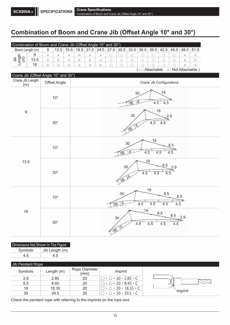
Crane SpecificationsCombination of Boom and Crane Jib (Offset Angle 10° and 30°)
SPECIFICATIONSSCX800A-3
Jib Pendant Rope
Symbols Length (m) Rope Diameter (mm) Imprint
Imprint
2.9 2.85 20 □・△・20・2.85・C8.5 8.45 20 □・△・20・8.45・C18 18.35 20 □・△・20・18.35・C30 29.5 20 □・△・20・29.5・C
Crane Jib (Offset Angle 10° and 30°)Crane Jib Length
(m) Offset Angle Crane Jib Configurations
9
10°9B 4
30 18
30°
9B4
3018
2.9
13.5
10°9B 4
3018
8.5
30°
9B4
3018
8.5
4.5 4.5 4.52.9
18
10°
9B 4
3018
8.58.5
30°
9B4
30
188.5 8.5 2.9
Dimensions Not Shown In The FigureSymbols Jib Length (m)
4.5 4.5
Combination of Boom and Crane Jib (Offset Angle 10° and 30°)Boom Length (m) 9 12.5 15.5 18.5 21.5 24.5 27.5 30.5 33.5 36.5 39.5 42.5 45.5 48.5 51.5
Jib
Leng
th
(m) 9
13.518
( : Attachable : Not Attachable )
Combination of Boom and Crane Jib (Offset Angle 10° and 30°)
Check the pendant rope with referring to the imprints on the rope end.

13
Working Ranges
Main Boom
80 t Hook
Hei
ght A
bove
Gro
und
(m)
Working Radius (m)
20 t Hook40 t Hook
0
5
10
15
20
25
30
35
40
45
50
55
60
5 10 15 20 25 30 35 40
9.5
12.5
15.518.5
21.5
24.5
27.5
30.5
33.5
36.5
39.5
42.5
45.5
48.5
51.5
54.5
80°
30°
45 501.1m
55
40°
70° 60° 50°
1.87
5m1.
785m
(Link
shoe
s)(F
lat sh
oes)
5.1m
4.9m
4.8m
Crane SpecificationsWorking Ranges
SPECIFICATIONS SCX800A-3

14
Aux. Sheave H
eigh
t Abo
ve G
roun
d (m
)
Working Radius (m)
7 t Hook
0
5
10
15
20
25
30
35
40
45
50
55
60
5 10 15 20 25 30 35 40
12.5
15.518.5
21.5
24.5
27.5
30.5
33.5
36.5
39.5
42.5
45.5
48.5
51.5
80°
45 50 55
70° 60° 50°
30°
40°
1.1m
1.87
5m
3.3m
1.78
5m(L
ink sh
oes)
(Flat
shoe
s)
Crane SpecificationsWorking Ranges
SPECIFICATIONSSCX800A-3

15
18 m Crane Jib (Offset Angle 10° and 30°)
Working Radius (m)
Hei
ght A
bove
Gro
und
(m)
7t Hook
Crane SpecificationsWorking Ranges
SPECIFICATIONS SCX800A-3
0
5
10
15
20
25
30
35
40
45
50
55
60
5 10 15 20 25 30 35 40
27.5
30.5
33.5
36.5
39.5
42.5
45.5
80°
45 50 55
70° 60° 50°
30°
40°
65
1.1m
10°
1.87
5m
3.3m
30°
1.78
5m(L
ink sh
oes)
(Flat
shoe
s)
Offset Angle 30°
Offset Angle 10°

16
Gross Rated Load Table
Main Boom (1/2)
unit ton
3.3 80.00 3.9mx 3.3 3.5 76.50 70.60t 4.4mx 3.5 4 70.00 69.50 63.30t 4
4.5 62.30 62.15 62.00 4.5 5 56.30 56.15 56.00 53.55 5
5.5 51.35 51.20 50.30 47.95 45.75 6.1mx 6.6mx 5.5 6 46.40 46.30 45.35 43.35 41.50 39.10t 34.60t 7.2mx 6 7 38.60 38.55 37.80 36.30 34.95 33.70 32.50 30.50t 7 8 31.90 31.85 31.75 31.20 30.10 29.15 28.20 27.30 8 9 27.15 27.05 26.95 26.90 26.40 25.60 24.85 24.10 9
10 9.5mx 23.50 23.35 23.30 23.20 22.80 22.15 21.50 10 12 25.25t 18.50 18.35 18.30 18.15 18.10 18.05 17.60 12 14 12.1mx 15.05 14.95 14.80 14.75 14.70 14.60 14 16 18.30t 14.7mx 12.55 12.45 12.35 12.30 12.15 16 18 14.10t 17.3mx 10.65 10.55 10.50 10.35 18 20 11.35t 19.9mx 9.20 9.10 8.95 20 22 9.35t 8.10 8.00 7.85 22 24 22.5mx 7.10 6.95 24 26 7.85t 25.1mx 6.20 26 28 6.65t 27.7mx 28 30 5.65t 30
1. The rated loads are determined according to EN13000 rating with the machineon firm level ground.
2. The figures surrounded by bold lines are based on factors other than those which would cause a tipping condition.
3. To calculate the maximum load that can actually be lifted, deduct weight of all l ifting accessories, such as boom hook, from figures shown above.
4. Working radius is the horizontal distance from the slewing center to the center of gravity of a l ifted load.
5. The counter weight is shown in the below table.
6. The relations between the reeving part number of rope and the maximum rated loads is shown in the table next page.
Upper weightCrawler shoeLink shoesFlat shoes
Lower weight28.2 -28.2 4.0
WorkingRadius
(m)
Boom Length ( m ) WorkingRadius
(m)9.5 12.5 15.5 18.5 21.5 24.5 27.5 30.5
Crane SpecificationsGross Rated Load Table
SPECIFICATIONSSCX800A-3

17
Main Boom (2/2)
Crane SpecificationsGross Rated Load Table
SPECIFICATIONS SCX800A-3
unit ton
6 7.7mx 6 7 27.45t 8.3mx 8.8mx 7 8 26.40 24.70t 22.50t 9.4mx 9.9mx 8 9 23.35 22.70 22.00 20.50t 18.90t 10.4mx 11.0mx 11.5mx 9
10 20.85 20.35 19.75 19.25 18.70 17.40t 15.95t 13.75t 10 12 17.10 16.70 16.25 15.85 15.40 14.95 14.55 13.60 12 14 14.40 14.10 13.65 13.35 13.00 12.60 12.25 12.00 14 16 12.05 12.00 11.70 11.45 11.15 10.80 10.50 10.30 16 18 10.25 10.20 10.05 9.95 9.70 9.35 9.10 8.90 18 20 8.85 8.80 8.65 8.60 8.45 8.20 7.95 7.80 20 22 7.75 7.65 7.50 7.45 7.35 7.20 7.00 6.85 22 24 6.80 6.75 6.60 6.55 6.40 6.30 6.15 6.05 24 26 6.05 6.00 5.85 5.75 5.65 5.50 5.40 5.35 26 28 5.45 5.35 5.20 5.10 5.00 4.85 4.75 4.70 28 30 4.90 4.80 4.65 4.55 4.45 4.30 4.20 4.15 30 32 30.3mx 4.35 4.20 4.10 3.95 3.85 3.70 3.65 32 34 4.80t 32.9mx 3.75 3.65 3.55 3.40 3.30 3.25 34 36 4.15t 35.5mx 3.30 3.20 3.05 2.90 2.85 36 38 3.50t 3.00 2.85 2.70 2.60 2.55 38 40 38.1mx 2.60 2.45 2.30 2.25 40 42 2.95t 40.7mx 2.15 2.05 1.95 42 44 2.50t 43.3mx 1.80 1.75 44 46 2.00t 45.9mx 1.50 46 48 1.60t 1.30 48
39.5 42.5 45.5 48.5 51.5 54.533.5 36.5
WorkingRadius
(m)
Boom Length ( m ) WorkingRadius
(m)
The relations between the reeving part number of rope and the maximum rated loadsHook Capacity Hook Weight
( t ) ( t ) 10 falls 9 falls 8 falls 7 falls 6 falls 5 falls 4 falls 3 falls 2 falls 1 fall80 0.80 80 63 56 49 42 35 28 21 14 -40 0.52 - - - - 40 35 28 21 14 -20 0.41 - - - - - - - 20 14 -7 0.26 - - - - - - - - - 7
Maximum rated loads ( t )

18
Aux. Sheave (1/2)
unit ton
4.7 7.00 5.2mx 4.7 5 7.00 7.00t 5.8mx 5
5.5 7.00 7.00 7.00t 6.3mx 6.9mx 5.5 6 7.00 7.00 7.00 7.00t 7.00t 7.4mx 6 7 7.00 7.00 7.00 7.00 7.00 7.00t 7 8 7.00 7.00 7.00 7.00 7.00 7.00 7.00 8 9 7.00 7.00 7.00 7.00 7.00 7.00 7.00 9
10 7.00 7.00 7.00 7.00 7.00 7.00 7.00 10 12 7.00 7.00 7.00 7.00 7.00 7.00 7.00 12 14 13.2mx 7.00 7.00 7.00 7.00 7.00 7.00 14 16 7.00t 15.8mx 7.00 7.00 7.00 7.00 7.00 16 18 7.00t 7.00 7.00 7.00 7.00 7.00 18 20 18.4mx 7.00 7.00 7.00 7.00 20 22 7.00t 21.0mx 7.00 7.00 7.00 22 24 7.00t 23.6mx 6.90 6.75 24 26 7.00t 6.15 6.00 26 28 26.2mx 5.35 28 30 6.10t 28.8mx 30 32 5.15t 32
1. The rated loads are determined according to EN13000 rating with the machine on firm level ground.2. The figures surrounded by bold lines are based on factors other than those which would cause a tipping condition.3. To calculate the maximum load that can actually be lifted, deduct weight of all l i fting accessories, such as boom hook and jib hook, from figures shown above.4. Working radius is the horizontal distance from the slewing center to the center of gravity of a l ifted load.5. The counter weight is shown in the below table.
6. Hook weight are shown in the table next page. Flat shoes 28.2 4.0
Crawler shoe Upper weight Lower weightLink shoes 28.2 -
24.5 27.5 30.5
WorkingRadius
(m)
Boom Length ( m ) WorkingRadius
(m)12.5 15.5 18.5 21.5
Crane SpecificationsGross Rated Load Table
SPECIFICATIONSSCX800A-3

19
Aux. Sheave (2/2)
unit ton
7 8.5mx 7 8 7.00t 9.1mx 9.6mx 8 9 7.00 7.00t 7.00t 10.2mx 10.7mx 11.2mx 11.4mx 9
10 7.00 7.00 7.00 7.00t 7.00t 7.00t 7.00t 10 12 7.00 7.00 7.00 7.00 7.00 7.00 7.00 12 14 7.00 7.00 7.00 7.00 7.00 7.00 7.00 14 16 7.00 7.00 7.00 7.00 7.00 7.00 7.00 16 18 7.00 7.00 7.00 7.00 7.00 7.00 7.00 18 20 7.00 7.00 7.00 7.00 7.00 7.00 7.00 20 22 7.00 7.00 7.00 7.00 7.00 6.95 6.70 22 24 6.65 6.55 6.40 6.35 6.20 6.05 5.90 24 26 5.85 5.80 5.65 5.55 5.45 5.30 5.15 26 28 5.25 5.15 5.00 4.90 4.80 4.65 4.50 28 30 4.70 4.60 4.45 4.35 4.25 4.10 3.95 30 32 31.4mx 4.10 3.95 3.85 3.75 3.60 3.45 32 34 4.35t 3.70 3.55 3.45 3.30 3.15 3.05 34 36 3.20 3.10 2.95 2.80 2.65 36 38 36.6mx 2.75 2.65 2.50 2.35 38 40 3.10t 39.2mx 2.35 2.20 2.05 40 42 2.60t 41.8mx 1.95 1.80 42 44 2.10t 1.70 1.55 44 46 44.4mx 1.35 46 48 1.65t 46.5mx 48 50 1.30t 50
The hook weight
207
0.800.520.410.26
Hook Capacity Hook Weight( t ) ( t )8040
WorkingRadius
(m)
Boom Length ( m ) WorkingRadius
(m)42.5 45.5 48.5 51.533.5 36.5 39.5
Crane SpecificationsGross Rated Load Table
SPECIFICATIONS SCX800A-3

20
Main Boom with Aux. Sheave (1/2)
unit ton
3.9 70.60 4.4mx 3.9 4 69.35 63.10t 4
4.5 61.95 61.75 4.5 5 55.90 55.75 53.20 5
5.5 50.95 49.95 47.60 45.35 6.1mx 6.6mx 5.5 6 46.05 45.00 43.00 41.15 38.75t 34.25t 7.2mx 6 7 38.30 37.45 36.00 34.55 33.35 32.15 30.10t 7 8 31.60 31.50 30.85 29.75 28.75 27.85 26.90 8 9 26.80 26.70 26.65 26.05 25.25 24.45 23.70 9
10 23.25 23.10 23.05 22.95 22.45 21.80 21.15 10 12 18.25 18.10 18.00 17.90 17.85 17.75 17.25 12 14 12.1mx 14.80 14.70 14.55 14.50 14.40 14.30 14 16 18.05t 14.7mx 12.30 12.15 12.10 12.00 11.90 16 18 13.85t 17.3mx 10.40 10.30 10.20 10.10 18 20 11.10t 19.9mx 8.90 8.80 8.70 20 22 9.10t 7.85 7.70 7.60 22 24 22.5mx 6.80 6.65 24 26 7.60t 25.1mx 5.95 26 27 6.40t 27.7mx 27 28 5.40t 28
1. The rated loads are determined according to EN13000 rating with the machine on firm level ground.2. The figures surrounded by bold lines are based on factors other than those which
would cause a tipping condition.3. To calculate the maximum load that can actually be lifted, deduct weight of all l ifting accessories, such as boom hook and jib hook, from figures shown above.4. Working radius is the horizontal distance from the slewing center to the center of gravity of a l ifted load.5. The counter weight is shown in the below table.
6. The relations between the reeving part number of rope and the maximum rated loadsFlat shoes 28.2 4.0
Crawler shoe Upper weight Lower weightLink shoes 28.2 -
21.5 24.5 27.5 30.5
WorkingRadius
(m)
Boom Length ( m ) WorkingRadius
(m)12.5 15.5 18.5
Crane SpecificationsGross Rated Load Table
SPECIFICATIONSSCX800A-3

21
Main Boom with Aux. Sheave (2/2)
unit ton
6 7.7mx 6 7 27.10t 8.3mx 8.8mx 7 8 26.00 24.30t 22.10t 9.4mx 9.9mx 8 9 22.95 22.35 21.60 20.10t 18.45t 10.4mx 11.0mx 9
10 20.50 19.95 19.35 18.85 18.25 17.00t 15.50t 10 12 16.75 16.35 15.85 15.45 15.00 14.55 14.10 12 14 14.05 13.70 13.25 12.95 12.60 12.20 11.85 14 16 11.75 11.70 11.35 11.05 10.75 10.40 10.05 16 18 9.95 9.90 9.75 9.55 9.25 8.95 8.65 18 20 8.55 8.50 8.35 8.25 8.10 7.80 7.50 20 22 7.45 7.35 7.20 7.15 7.00 6.80 6.55 22 24 6.55 6.45 6.30 6.25 6.10 5.95 5.75 24 26 5.80 5.70 5.55 5.45 5.35 5.20 5.05 26 28 5.15 5.05 4.90 4.80 4.70 4.55 4.40 28 30 4.60 4.50 4.35 4.25 4.15 4.00 3.85 30 32 30.3mx 4.05 3.90 3.80 3.65 3.50 3.40 32 34 4.55t 32.9mx 3.50 3.40 3.25 3.10 2.95 34 36 3.85t 35.5mx 3.00 2.90 2.75 2.60 36 38 3.20t 2.70 2.55 2.40 2.25 38 40 38.1mx 2.30 2.15 2.00 40 42 2.70t 40.7mx 1.90 1.75 42 44 2.20t 43.3mx 1.50 44 46 1.75t 45.9mx 46 48 1.30t 48
WorkingRadius
(m)
Boom Length ( m ) WorkingRadius
(m)42.5 45.5 48.5 51.533.5 36.5 39.5
The relations between the reeving part number of rope and the maximum rated loadsHook Capacity Hook Weight
( t ) ( t ) 10 falls 9 falls 8 falls 7 falls 6 falls 5 falls 4 falls 3 falls 2 falls 1 fall80 0.80 80 63 56 49 42 35 28 21 14 -40 0.52 - - - - 40 35 28 21 14 -20 0.41 - - - - - - - 20 14 -7 0.26 - - - - - - - - - 7
Maximum rated loads ( t )
Crane SpecificationsGross Rated Load Table
SPECIFICATIONS SCX800A-3

22
Crane Jib (1/4)
Unit ; tonBoom Boom
length m) length m)Jib Jib
length m) length m)
7.00 11.2mx 10.2mx 11.8mx7.00 12.3mx 7.00t 12.8mx 7.00t 12.9mx 7.00t 13.3mx7.00 7.00t 7.00 15.3mx 7.00t 7.00 7.00t 7.00 15.8mx 7.00t7.00 7.00 7.00 7.00t 7.00 7.00 7.00 7.00 7.00t 7.007.00 7.00 7.00 7.00 7.00 18.2mx 7.00 7.00 7.00 7.00 7.00 18.7mx7.00 7.00 7.00 6.75 6.90 5.25t 7.00 7.00 7.00 6.85 6.95 5.20t7.00 7.00 7.00 6.40 6.80 5.15 7.00 7.00 7.00 6.50 6.85 5.107.00 7.00 7.00 6.10 6.70 5.05 7.00 7.00 7.00 6.25 6.75 5.007.00 7.00 7.00 5.85 6.65 4.85 6.90 7.00 7.00 6.00 6.60 4.906.25 6.40 6.35 5.65 6.45 4.75 6.10 6.25 6.25 5.80 6.35 4.855.60 5.70 5.70 5.45 5.80 4.65 5.45 5.60 5.55 5.60 5.65 4.755.00 5.10 5.15 5.30 5.25 4.50 4.90 5.00 5.00 5.20 5.10 4.604.55 4.60 4.65 4.80 4.75 4.35 4.40 4.50 4.50 4.70 4.60 4.45
33.8mx 4.15 4.25 4.35 4.30 4.25 3.95 4.05 4.10 4.25 4.15 4.354.15t 34.4mx 3.85 3.95 3.95 4.10 3.60 3.65 3.70 3.85 3.80 4.00
4.10t 3.50 3.60 3.60 3.70 36.4mx 37.0mx 3.35 3.45 3.45 3.6038.9mx 3.30 3.40 3.55t 3.50t 3.10 3.15 3.15 3.303.45t 3.05 3.10 40.6mx 41.5mx 2.90 3.00
42.3mx 43.4mx 3.00t 2.95t 2.65 2.703.00t 2.90t 44.9mx 45.9mx
2.55t 2.50t
1. The rated loads are determined according to EN13000 rating with the machine on firm level ground. 2. The figures surrounded by bold lines are based on factors other than those which would cause a tipping condition.3. To calculate the maximum load that can actually be lifted, deduct weight of all l i fting accessories, such as boom hook and jib hook, from figures shown above.4. Working radius is the horizontal distance from the slewing center to the center of gravity of a l ifted load.5. The counter weight is shown in the below table.
6. Hook weight are shown in the table next page.
Crawler shoe Upper weight Lower weight
Flat shoes 28.2-
4.0Link shoes 28.2
48 48
44 4446 46
42 4240 4038 3836 3634 3432 3230 3028 2826 2624 2422 2220 2018 1816 1614 1412 1210 109.6 9.6
Workingradius m)
Workingradius m)
30
Jiboffset30 10 30 10 30 10
Jiboffset 10 30 10 30 10
13.5 18
27.5 30.5
9 13.5 18 9
Crane SpecificationsGross Rated Load Table
SPECIFICATIONSSCX800A-3

23
Crane Jib (2/4)
Unit ; tonBoom Boom
length m) length m)Jib Jib
length m) length m)
10.7mx 11.3mx7.00t 13.4mx 12.3mx 13.9mx 7.00t 12.8mx7.00 7.00t 7.00t 7.00t 7.00 7.00t 14.4mx7.00 7.00 7.00 16.3mx 7.00 7.00 7.00 7.00 16.9mx 7.00t7.00 7.00 7.00 7.00t 7.00 19.3mx 7.00 7.00 7.00 7.00t 7.00 19.8mx7.00 7.00 7.00 6.90 7.00 5.15t 7.00 7.00 7.00 7.00 7.00 5.25t7.00 7.00 7.00 6.60 6.90 5.15 7.00 7.00 7.00 6.70 6.95 5.257.00 7.00 7.00 6.35 6.80 5.00 7.00 7.00 7.00 6.45 6.85 5.106.75 6.95 6.90 6.10 6.65 4.90 6.65 6.90 6.80 6.20 6.80 4.955.95 6.15 6.10 5.90 6.20 4.85 5.85 6.10 6.00 6.00 6.15 4.855.30 5.45 5.45 5.70 5.55 4.75 5.20 5.40 5.35 5.65 5.45 4.804.75 4.90 4.85 5.10 4.95 4.65 4.65 4.80 4.75 5.05 4.90 4.704.25 4.35 4.35 4.55 4.45 4.55 4.15 4.30 4.30 4.50 4.40 4.653.85 3.90 3.95 4.10 4.05 4.30 3.75 3.85 3.85 4.05 3.95 4.203.45 3.55 3.55 3.70 3.65 3.90 3.35 3.45 3.45 3.65 3.55 3.803.15 3.20 3.25 3.35 3.30 3.50 3.00 3.10 3.15 3.25 3.20 3.45
39.0mx 39.6mx 2.95 3.05 3.00 3.20 2.75 2.80 2.85 2.95 2.90 3.103.00t 2.95t 2.65 2.75 2.75 2.90 41.6mx 2.50 2.55 2.65 2.65 2.80
43.2mx 2.50 2.50 2.60 2.50t 42.1mx 2.30 2.40 2.40 2.552.55t 2.30 2.35 2.50t 45.8mx 2.15 2.15 2.30
47.5mx 2.15 2.10t 46.6mx 1.95 2.052.15t 48.5mx 2.10t 1.80 1.85
2.10t 50.1mx 51.1mx1.75t 1.75t
The hook weight
20 0.417 0.26
Hook Capacity Hook Weight( t ) ( t )80 0.8040 0.52
36.5
9 13.5 18
33.5
9 13.5 18
Jiboffset 10 30 10 30 10 30 10 30 10 30 10 30
Jiboffset
Workingradius m)
Workingradius m)
9 910 1012 1214 1416 1618 1820 2022 2224 2426 2628 2830 3032 3234 3436 3638 3840 4042 4244 4446 46
50 5048 48
52 5254 54
Crane SpecificationsGross Rated Load Table
SPECIFICATIONS SCX800A-3

24
Crane Jib (3/4)
Unit ; tonBoom Boom
length m) length m)Jib Jib
length m) length m)
11.8mx7.00t 13.4mx 12.4mx 13.9mx7.00 14.5mx 7.00t 15.0mx 7.00t 15.0mx 7.00t 15.5mx7.00 7.00t 7.00 17.4mx 7.00t 7.00 7.00t 7.00 7.00t7.00 7.00 7.00 7.00t 7.00 7.00 7.00 7.00 7.007.00 7.00 7.00 7.00 7.00 20.3mx 7.00 7.00 7.00 7.00 7.00 20.9mx7.00 7.00 7.00 6.80 6.95 5.15t 7.00 7.00 7.00 6.90 7.00 5.15t7.00 7.00 7.00 6.55 6.85 5.10 7.00 7.00 7.00 6.65 6.90 5.106.50 6.75 6.65 6.30 6.65 5.00 6.40 6.70 6.45 6.40 6.50 5.005.70 5.95 5.85 6.10 5.95 4.95 5.65 5.90 5.80 6.15 5.80 4.905.05 5.25 5.20 5.50 5.30 4.90 4.95 5.20 5.10 5.45 5.20 4.854.50 4.65 4.65 4.90 4.75 4.80 4.40 4.60 4.55 4.85 4.65 4.754.00 4.15 4.15 4.40 4.25 4.60 3.90 4.05 4.05 4.30 4.15 4.503.55 3.70 3.70 3.90 3.80 4.10 3.45 3.60 3.60 3.85 3.70 4.053.20 3.30 3.30 3.50 3.40 3.70 3.10 3.20 3.20 3.45 3.30 3.602.85 2.95 3.00 3.15 3.05 3.30 2.75 2.85 2.85 3.05 2.95 3.252.55 2.65 2.65 2.80 2.75 3.00 2.45 2.55 2.55 2.75 2.65 2.902.30 2.35 2.40 2.55 2.50 2.70 2.20 2.25 2.30 2.45 2.40 2.602.05 2.10 2.15 2.25 2.25 2.40 1.95 2.00 2.05 2.20 2.15 2.35
44.2mx 44.7mx 1.95 2.00 2.00 2.15 1.75 1.80 1.85 1.95 1.90 2.102.05t 2.05t 1.75 1.80 1.80 1.95 46.8mx 47.3mx 1.65 1.70 1.70 1.85
48.4mx 49.2mx 1.65 1.75 1.65t 1.65t 1.45 1.50 1.50 1.651.70t 1.70t 1.45 1.55 51.0mx 51.8mx 1.35 1.45
52.6mx 53.7mx 1.35t 1.35t 52.7mx 53.5mx1.40t 1.40t 1.30t 1.30t
1. The rated loads are determined according to EN13000 rating with the machine on firm level ground. 2. The figures surrounded by bold lines are based on factors other than those which would cause a tipping condition.3. To calculate the maximum load that can actually be lifted, deduct weight of all l i fting accessories, such as boom hook and jib hook, from figures shown above.4. Working radius is the horizontal distance from the slewing center to the center of gravity of a l ifted load.5. The counter weight is shown in the below table.
Link shoesFlat shoes
6. Hook weight are shown in the table next page.
Crawler shoe Upper weight Lower weight28.2 -28.2 4.0
56 56
52 5254 54
48 4846 46
50 50
44 4442 4240 4038 3836 3634 3432 3230 3028 2826 2624 2422 2220 2018 1816 1614 1412 1210 109 9
Workingradius m)
Workingradius m)
10 30 10 3010 30 10 30 10 30
Jiboffset 10 30
Jiboffset
13.5 189
39.5 42.5
13.5 18 9
Crane SpecificationsGross Rated Load Table
SPECIFICATIONSSCX800A-3

25
Crane Jib (4/4)
Unit ; tonBoom Boom
length m) length m)Jib Jib
length m) length m)
12.9mx7.00t 15.6mx 14.5mx7.00 7.00t 7.00t7.00 7.00 7.007.00 7.00 7.00 7.007.00 7.00 7.00 6.95 7.007.00 7.00 7.00 6.70 6.95 5.156.20 6.50 6.25 6.50 6.25 5.055.50 5.80 5.55 6.00 5.60 4.954.85 5.10 4.95 5.35 5.00 4.854.25 4.50 4.40 4.75 4.50 4.803.75 3.95 3.90 4.20 4.00 4.403.35 3.50 3.45 3.75 3.60 3.952.95 3.10 3.10 3.30 3.20 3.502.65 2.75 2.75 2.95 2.85 3.152.35 2.45 2.45 2.65 2.55 2.802.05 2.15 2.15 2.35 2.25 2.501.80 1.90 1.90 2.05 2.00 2.251.60 1.65 1.70 1.80 1.80 2.001.40 1.45 1.50 1.60 1.55 1.75
48.9mx 49.4mx 1.30 1.40 1.40 1.551.30t 1.30t 51.0mx 51.0mx 1.35
1.30t 1.30t 52.5mx1.30t
The hook weight
7 0.26
80 0.8040 0.5220 0.41
Hook Capacity Hook Weight( t ) ( t )
9
Jiboffset 10 30
Jiboffset
Workingradius m)
Workingradius m)
10 1012 1214 1416 1618 1820 2022 2224 2426 2628 2830 3032 3234 3436 3638 3840 4042 4244 44
48
13.5 18
10 30 10 30
50
46
45.5
525456
525456
50
4648
Crane SpecificationsGross Rated Load Table
SPECIFICATIONS SCX800A-3

26
Main Boom with Crane Jib (1/4)
Unit ; tonBoom Boom
length m) length m)Jib Jib
length m) length m)
33.45 33.20 33.05 32.60 32.55 31.95 7.2mx 7.2mx 7.2mx 7.2mx 7.2mx 7.2mx31.35 31.15 30.95 30.55 30.50 29.90 29.35t 29.10t 28.95t 28.55t 28.50t 27.95t27.05 26.85 26.65 26.30 26.20 25.70 26.15 25.95 25.75 25.45 25.35 24.8523.65 23.50 23.30 23.00 22.85 22.45 22.95 22.75 22.55 22.25 22.15 21.7021.00 20.85 20.60 20.35 20.20 19.80 20.35 20.20 20.00 19.75 19.60 19.2016.95 16.85 16.60 16.40 16.15 15.90 16.45 16.35 16.10 15.90 15.70 15.4013.70 13.60 13.35 13.20 13.00 12.80 13.60 13.50 13.30 13.15 12.95 12.7011.30 11.20 11.00 10.85 10.65 10.45 11.20 11.10 10.90 10.75 10.55 10.35
9.50 9.45 9.20 9.10 8.85 8.75 9.40 9.35 9.10 9.00 8.80 8.658.10 8.05 7.80 7.75 7.50 7.40 8.00 7.95 7.70 7.65 7.40 7.307.00 7.00 6.70 6.65 6.40 6.35 6.90 6.85 6.60 6.55 6.30 6.206.10 6.10 5.85 5.80 5.50 5.50 6.00 5.95 5.70 5.65 5.40 5.35
25.1mx 25.1mx 25.1mx 25.1mx 25.1mx 25.1mx 5.25 5.20 4.95 4.95 4.65 4.655.70t 5.70t 5.40t 5.40t 5.10t 5.10t 27.7mx 27.7mx 27.7mx 27.7mx 27.7mx 27.7mx
4.70t 4.70t 4.45t 4.40t 4.15t 4.15t
1. The rated loads are determined according to EN13000 rating with the machine on firm level ground.2. To calculate the maximum load that can actually be lifted, deduct weight of
all l ifting accessories, such as boom hook and jib hook, from figures shown above.3. Working radius is the horizontal distance from the slewing center to the center of gravity of a l ifted load. 4. The counter weight is shown in the below table.
Link shoesFlat shoes
5. The relations between the reeving part number of rope and the maximum rated loads is shown in the table next page.
Crawler shoe Upper weight Lower weight28.2 -28.2 4.0
30 3028 2826 2624 2422 2220 2018 1816 1614 1412 1210 109 98 87 7
6.6 6.6
Workingradius m)
Workingradius m)
30
Jiboffset30 10 30 10 30 10
Jiboffset 10 30 10 30 10
27.5 30.5
9 13.5 18 9 13.5 18
Crane SpecificationsGross Rated Load Table
SPECIFICATIONSSCX800A-3

27
Main Boom with Crane Jib (2/4)
Unit ; tonBoom Boom
length m) length m)Jib Jib
length m) length m)
7.7mx 7.7mx 7.7mx 7.7mx 7.7mx 7.7mx26.30t 26.10t 25.95t 25.60t 25.55t 25.00t 8.3mx 8.3mx 8.3mx 8.3mx 8.3mx 8.3mx25.25 25.05 24.90 24.55 24.50 24.00 23.55t 23.35t 23.20t 22.90t 22.80t 22.35t22.20 22.00 21.85 21.55 21.45 21.00 21.55 21.40 21.20 20.95 20.85 20.4019.70 19.55 19.35 19.10 18.95 18.60 19.20 19.05 18.85 18.60 18.45 18.1015.95 15.85 15.60 15.40 15.25 14.95 15.55 15.45 15.25 15.05 14.85 14.5513.25 13.15 12.90 12.75 12.55 12.30 12.95 12.85 12.60 12.45 12.25 12.0011.10 11.00 10.80 10.65 10.45 10.25 10.95 10.85 10.60 10.50 10.25 10.05
9.30 9.20 9.00 8.90 8.70 8.50 9.20 9.15 8.95 8.80 8.65 8.457.90 7.85 7.60 7.50 7.30 7.15 7.80 7.75 7.55 7.45 7.25 7.106.75 6.70 6.50 6.40 6.20 6.10 6.70 6.65 6.45 6.35 6.15 6.005.85 5.80 5.60 5.55 5.30 5.20 5.80 5.75 5.50 5.45 5.25 5.155.10 5.10 4.85 4.80 4.55 4.50 5.05 5.00 4.75 4.70 4.50 4.404.50 4.45 4.20 4.20 3.95 3.90 4.40 4.35 4.15 4.10 3.85 3.803.95 3.95 3.70 3.70 3.40 3.40 3.85 3.85 3.60 3.55 3.30 3.30
30.3mx 30.3mx 30.3mx 30.3mx 30.3mx 30.3mx 3.40 3.40 3.15 3.15 2.85 2.853.85t 3.85t 3.60t 3.60t 3.35t 3.35t 32.9mx 32.9mx 32.9mx 32.9mx 32.9mx 32.9mx
3.20t 3.20t 2.95t 2.95t 2.70t 2.70t
The relations between the reeving part number of rope and the maximum rated loads
5 falls 4 falls 3 falls 2 falls35 2835 28 21 14
21 14
14- - 20- - - -
( t )8040207
( t )0.800.520.410.26
36.5
Hook Capacity Hook Weight Maximum rated loads ( t )
9 13.5 18
33.5
9 13.5 18
Jiboffset 10 30 10 30 10 30 10 30 10 30 10 30
Jiboffset
Workingradius m)
Workingradius m)
6 67 78 89 9
10 1012 1214 1416 1618 1820 2022 2224 2426 2628 2830 3032 3234 3436 36
1 fall---7
Crane SpecificationsGross Rated Load Table
SPECIFICATIONS SCX800A-3

28
Main Boom with Crane Jib (3/4)
Unit ; tonBoom Boom
length m) length m)Jib Jib
length m) length m)
8.8mx 8.8mx 8.8mx 8.8mx 8.8mx 8.8mx21.40t 21.20t 21.05t 20.75t 20.65t 20.20t 9.4mx 9.4mx 9.4mx 9.4mx 9.4mx 9.4mx20.85 20.70 20.50 20.25 20.15 19.70 19.35t 19.20t 19.00t 18.75t 18.65t 18.25t18.60 18.45 18.25 18.00 17.85 17.50 18.10 17.95 17.75 17.50 17.40 17.0015.10 14.95 14.75 14.55 14.40 14.10 14.70 14.55 14.40 14.15 14.05 13.7012.50 12.40 12.20 12.05 11.85 11.60 12.20 12.10 11.90 11.75 11.55 11.3010.55 10.50 10.25 10.10 9.90 9.70 10.30 10.25 10.00 9.85 9.65 9.45
9.05 8.95 8.75 8.60 8.40 8.25 8.80 8.75 8.50 8.40 8.20 8.007.70 7.60 7.40 7.30 7.10 6.95 7.60 7.55 7.30 7.20 7.00 6.856.55 6.50 6.30 6.20 6.00 5.90 6.50 6.45 6.25 6.15 5.95 5.805.65 5.60 5.40 5.30 5.10 5.00 5.55 5.50 5.30 5.25 5.05 4.904.90 4.85 4.60 4.55 4.35 4.25 4.80 4.75 4.55 4.50 4.30 4.204.25 4.20 4.00 3.95 3.70 3.65 4.15 4.15 3.90 3.85 3.65 3.553.70 3.70 3.45 3.40 3.20 3.15 3.60 3.60 3.35 3.30 3.10 3.053.25 3.20 3.00 2.95 2.70 2.70 3.15 3.10 2.90 2.85 2.65 2.602.85 2.80 2.60 2.55 2.30 2.30 2.75 2.70 2.50 2.45 2.25 2.20
35.5mx 35.5mx 35.5mx 35.5mx 35.5mx 35.5mx 2.35 2.35 2.15 2.10 1.85 1.852.55t 2.55t 2.30t 2.30t 2.05t 2.05t 2.05 2.05 1.80 1.80 1.55 1.55
38.1mx 38.1mx 38.1mx 38.1mx 38.1mx 38.1mx2.05t 2.05t 1.80t 1.80t 1.55t 1.55t
1. The rated loads are determined according to EN13000 rating with the machine on firm level ground.2. To calculate the maximum load that can actually be lifted, deduct weight of
all l ifting accessories, such as boom hook and jib hook, from figures shown above.3. Working radius is the horizontal distance from the slewing center to the center of gravity of a l ifted load. 4. The counter weight is shown in the below table.
Link shoesFlat shoes
5. The relations between the reeving part number of rope and the maximum rated loads is shown in the table next page.
Crawler shoe
28.2 4.0
Upper weight Lower weight28.2 -
40 4042 42
38 3836 3634 3432 3230 3028 2826 2624 2422 2220 2018 1816 1614 1412 1210 109 98 87 7
Workingradius m)
Workingradius m)
10 30 10 3010 30 10 30 10 30
Jiboffset 10 30
Jiboffset
13.5 189 13.5 18 9
39.5 42.5
Crane SpecificationsGross Rated Load Table
SPECIFICATIONSSCX800A-3

29
Main Boom with Crane Jib (4/4)
Unit ; tonBoom Boom
length m) length m)Jib Jib
length m) length m)
9.9mx 9.9mx 9.9mx 9.9mx 9.9mx 9.9mx17.75t 17.60t 17.40t 17.15t 17.05t 16.65t17.55 17.4 17.20 17.0 16.85 16.514.25 14.15 13.95 13.75 13.60 13.3011.85 11.75 11.55 11.35 11.20 10.9510.00 9.90 9.70 9.55 9.35 9.15
8.50 8.45 8.25 8.10 7.90 7.707.35 7.25 7.05 6.95 6.75 6.556.35 6.30 6.05 5.95 5.75 5.605.45 5.40 5.20 5.10 4.95 4.804.70 4.65 4.45 4.35 4.15 4.054.05 4.00 3.80 3.75 3.55 3.453.50 3.45 3.25 3.20 3.00 2.903.00 3.00 2.75 2.75 2.50 2.452.60 2.60 2.35 2.35 2.10 2.052.25 2.25 2.00 2.00 1.75 1.701.90 1.90 1.70 1.70 1.45 1.401.65 1.65 1.40 1.40 39.0mx 38.8mx
40.7mx 40.7mx 40.7mx 40.7mx 1.30t 1.30t1.55t 1.55t 1.30t 1.30t
9
Jiboffset 10 30
Jiboffset
Workingradius m)
Workingradius m)
8 89 9
10 1012 1214 1416 1618 1820 2022 2224 2426 2628 2830 3032 32
3436 3638 3840 4042 42
45.5
44 44
13.5 18
10 30 10 30
34
The relations between the reeving part number of rope and the maximum rated loads
5 falls 4 falls 3 falls 2 falls35 2835 28 21 14
21 14
14- - 20- - - -
( t )8040207
( t )0.800.520.410.26
Hook Capacity Hook Weight Maximum rated loads ( t )1 fall
---7
Crane SpecificationsGross Rated Load Table
SPECIFICATIONS SCX800A-3

30
Clamshell SpecificationsDimensions and Specifications
Boom Length m 9.5 12.5 15.5Boom Angle ° 35 45 55 65 35 45 55 65 35 45 55 65Working Radius m 9.3 8.3 7.1 5.8 11.8 10.5 8.8 7.1 14.3 12.6 10.6 8.4Gross Rated Load t 6.5 6.5 6.5 6.5 6.5 6.5 6.5 6.5 6.5 6.5 6.5 6.5Lift L (D + H2) m 37.4 38.7 39.8 40.7 39.1 40.9 42.3 43.4 40.8 43.0 44.7 46.1Max. Digging Depth D m 36
Bucket DumpingHeight H2 m 1.4 2.7 3.8 4.7 3.1 4.9 6.3 7.4 4.8 7.0 8.7 10.1
Working Ranges
Boom Length m 18.5 21.5Boom Angle ° 35 45 55 65 35 45 55 65Working Radius m 16.7 14.7 12.3 9.6 19.2 16.8 14.0 10.9Gross Rated Load t 6.5 6.5 6.5 6.5 6.5 6.5 6.5 6.5Lift L (D + H2) m 42.5 45.1 47.2 48.9 44.2 47.2 49.7 51.7Max. Digging Depth D m 36
Bucket DumpingHeight H2 m 6.5 9.1 11.2 12.9 8.2 11.2 13.7 15.7
Cast type weight(Optional)
D
R3980
1100
Working Radius
H
H1H2
L
CA
1270
1905
1875
(1785
)
(1185
)
2150
1215
(1125
)
5915
(582
5)
6280 (6060)
1160
NOTE : ( ) In case of the flat shoes.
Clamshell SpecificationsDimensions and Specifications
SPECIFICATIONSSCX800A-3

31
Clamshell SpecificationsBucket Capacity m3 1.2Allowed Maximum Gross Weight for Clamshell Bucket and Captured Load Combined t 6.5
Boom Length m 9.5 to 21.5Maximum Digging Depth m 36Support Wire Rope Speed * m/min 105 Wire Rope Diameter 22.4 mmOpening/Closing Wire Rope Speed * m/min 105Boom Hoist Drum Wire Rope Speed (Raise) * m/min 67 Wire Rope Diameter 16.0 mmBoom Hoist Drum Wire Rope Speed (Lower) * m/min 67
Ground Contact Pressure kPa (kgf/cm²)
90.9 (0.93)(w/ Basic Boom, 1.2 m3 Clamshell Bucket, Link shoes)
94.9 (0.97)(w/ Basic Boom, 1.2 m3 Clamshell Bucket, Flat shoes)
Overall Operating Weight t Approximately 76(w/ Basic Boom, 1.2 m3 Clamshell Bucket)
NOTE : •Speeds marked with "*" may vary depending on load applied. •SI units are used for specifications. In parenthesis, conventional units are also indicated. •Specifications other than those shown above are the same as those shown in the crane specifications section.
Capacity ( m3 ) Weight ( t ) C (mm) H (mm) H1 (mm)1.2 3.1 2,600 3,100 3,700
Specifications
Gross Rated Load Table
Clamshell Bucket
unit ton
5.8 6.5 6.0 6.5
6.5 6.5 6.5
6.5 6.5 6.5
6.5 6.5 6.5
6.5 6.5 6.5 6.5
6.5 6.5
6.5 6.5 6.5
6.5
7.1mx 7.0 6.5t 8.4mx 8.0 6.5t 9.6mx 9.0 6.5t 10.9mx
10.0 9.3mx 6.5t 12.0 6.5t 11.8mx 14.0 6.5t 16.0 14.3mx 18.0 6.5t 16.7mx 20.0 6.5t 19.2mx 22.0 6.5t
1. Max. clamshell rating is 6.5 t.2. Mass of bucket plus load should not exceed clamshell ratings shown above. Following data are for a general digging application buckets.
Bucket Capacity 1.2 m3
Bucket Mass 3.1 t3. In case of clamshell application, a 9.5 m boom is recomenned as minimum length of boom, and max. boom length shall not exceed 21.5 m.4. Apparent specific gravity of lifting material : Earth ........... 1.7 to 1.8 t/m3 Gravel ......... 1.8 to 2.0 t/m3 5. The counter weight is shown in the next table.
6. Max. digging depth below ground shall be 36 m.
Boom Length ( m )21.5
Working
(m)Radius
9.5 12.5 15.5 18.5
Link shoeFlat shoe
Crawler shoe
28.2 4.0
Upper weight Lower weight28.2 -
Clamshell SpecificationsDimensions and Specifications
SPECIFICATIONS SCX800A-3

32
Weights and Dimensions of Disassembled UnitsDescription Qty Dimensions (mm) Weight (kg)
MachineryWith boom base
With front winch wire ropeWith boom hoist drum wire rope
With crawlerWith upper spreader
With lower weight
1
NOTE : ( ) In case of the flat shoes.
45600(45800)
MachineryWith front winch wire rope
With boom hoist drum wire ropeWith crawler
With upper spreaderWith lower weight
1
NOTE : ( ) In case of the flat shoes.
44400(44600)
MachineryWith boom base
With front winch wire ropeWith boom hoist drum wire rope
With upper spreader
1
11500
22104410
2810
3200
26700
MachineryWith front winch wire rope
With boom hoist drum wire ropeWith upper spreader
1
7200
22104410
2800
3200
25500
Crawler side frame (ASSY) 26280 (6060)
1075(1050)
810(800)
1150
(990
)
NOTE : ( ) In case of the flat shoes.
8400(7600)
Weights and Dimensions of Disassembled UnitsWeights and Dimensions List
Weights and Dimensions of Disassembled UnitsWeights and Dimensions ListTECHNICAL DATASCX800A-3
11500
3400(3200)
6280(6060)
3290
(320
0)
3400(3200)
6280(6060)
3290
(320
0)
Comply with the regulations when transporting."Weight" refers to the mass of each single unit.
・With upper house handrails, the weight of the main unit increases by 100 kg.・With catwalks, the weight of the main unit increases by 215 kg and the width of the main unit increases by 210 mm.

33
Weights and Dimensions of Disassembled UnitsDescription Qty Dimensions (mm) Weight (kg)
Counter weight (A):Standard 1
960
825
3400
9200
Counter weight (B):Standard 2
960
860
3400
9500
Counter weight (A):Optional 1
3200
745
970
9200
Counter weight (B):Optional 1
3200
960
690
9100
Counter weight (C):Optional 1
3200
960
827
9900
Weights and Dimensions of Disassembled UnitsWeights and Dimensions List TECHNICAL DATA SCX800A-3

34
Weights and Dimensions of Disassembled UnitsDescription Qty Dimensions (mm) Weight (kg)
Lower weight :In case of the flat shoes 2
1400 430
937 2020
Upper spreader 1
1706 333
765
285
Boom base (5.5)With connector pin
With exclusive crane backstop1
1670
5690
1720 1230
Boom top (4)With pendant rope 1
44201500
1770 1020
3 m boom insert (3)With connector pin
Without pendant rope1
31201500
1610
325
6 m boom insert (6)With connector pin
Without pendant rope1
61201500
1610
545
9 m boom insert (9)With connector pin
Without pendant rope1
91201500
1610 750
9 m special boom insert (9B)(crane jib combined use boom)
With connector pinWithout pendant rope
1
91201500
1630 755
Crane jib bottom (4.5)With connector pin
With jib strut1
4615850
860
490
Weights and Dimensions of Disassembled UnitsWeights and Dimensions ListTECHNICAL DATASCX800A-3

35
Weights and Dimensions of Disassembled UnitsDescription Qty Dimensions (mm) Weight (kg)
Crane jib top (4.5)without pendant rope 1
800
1080
4930
290
4.5 m jib insert (4.5)With connector pin
without pendant rope1 68
0
4600
640
140
Short jibWith connector pin 1
770125087
0
250
Pendant Rope (3)connect pin 1
L
d
25
Pendant Rope (6)connect pin 1
L
d
40
Pendant Rope (9)connect pin 1
L
d
55
Jib Pendant Rope (2.9)connect pin 1
L
d
15
Jib Pendant Rope (8.5)connect pin 1
L
d
25
Jib Pendant Rope (18)connect pin 1
L
d
45
Jib Pendant Rope (30)connect pin 1
L
d
65
L=3000
d=32
L=6000
d=32
L=9000
d=32
L=2850
d=20
Weights and Dimensions of Disassembled UnitsWeights and Dimensions List TECHNICAL DATA SCX800A-3
L=8450
d=20
L=18350
d=20
L=29500
d=20

36
Weights and Dimensions of Disassembled UnitsDescription Qty Dimensions (mm) Weight (kg)
80 t hook 1
660 450
1840
800
40 t hook 1
345690
1590 520
20t hook 1
31869014
95 410
7t hook 1
300300
990
260
Weights and Dimensions of Disassembled UnitsWeights and Dimensions ListTECHNICAL DATASCX800A-3

37
Equipment List Standard and Optional Equipment
: Standard : Optional : No setting
Item* are described in the last page of this list. Crane Clamshell
Lower
Structure
810 mm Crawler Shoe (Link shoes)800 mm Crawler Shoe (Flat shoes)Jack Up UnitCrawler Extension / Retraction System Steps Shoe Tension Unit *1 *1
Upper
Structure
Cab Up / Down Catwalk Under Cover (Bed Lower Surface) Working Light (× 2)Back Mirror (Left / Right)Gantry CylindersCentral Lubrication Unit (for Turntable Bearing) Drum Flange Cover Auto Idle StopEco WinchDrum MirrorDrum Light Winch Rope Retainer (Front Winch) Winch Rope Retainer (Rear Winch) Catwalk (Folding Type, Left / Right) Catwalk with Handrails (Folding Type, Left / Right) / *2 / *2
3400mm Width Counter Weight (Non-Cast Type)3200mm Width Counter Weight (Cast Type)Electric Fuel Pump Handrails (Folding Type)Winch with Front and Rear Free MechanismThird Winch (Rope not Included)
Cab
Air ConditionerSunvisorSunshadeWiper with Washer (Front Window, Cab Roof Window) Microphone & Loud-speakerAM / FM Radio (with Clock)Room LampCup Holder24 V Power Socket (× 2) Floor CarpetLevel Gauge (in Cab)Accelerator Pedal (Right Side)Arm Chair LeverCross Operation Lever (Lever Lock not Attached) / *2 / *2
Front Operation Lever (with Lever Lock) Seat without SuspensionSeat with Suspension / *2 / *2
Travel Operation Pedal (Cannot be installed when winch with free mechanism attached) Boom Hoist Operation Pedal *3
Swing Brake Operation Pedal *3
Equipment List Standard and Optional Equipment TECHNICAL DATA SCX800A-3

38
: Standard : Optional : No settingItem
* are described in the last page of this list. Crane Clamshell
Cab
FanFront / Rear Operation Lever, Brake Pedal PermutationFuel Burning HeaterAccelerator GripDrum Rotation Sensor (Front / Rear / Boom Hoist) *4
Speed Control Dial (Boom Hoist / Swing)Life Hanmer
Attachment
9.5 m Basic Boom (Boom Base: 5.5 m, Boom Top: 4 m) 3 m Boom Insert 6 m Boom Insert9 m Boom Insert9 m Special Boom Insert (9B)Parts Set for 9 m Crane Jib [9 m Basic Jib, Anti-two Block, Jib Mast] 4.5 m Crane Jib InsertParts Set for Auxiliary Sheave [Auxiliary Sheave, Auxiliary Sheave Anti-two Block] 80 t Hook (5 Sheaves)40 t Hook (3 Sheaves)20 t Hook (1 Sheave)7 t Hook
Wire
Rope
Front Winch ( 22.4) Mono Rope EP 3XF (40)IWRC 6 X Fi (25) *5
Rear Winch ( 22.4) Mono Rope EP 3XF (40)IWRC 6 X Fi (25) *6
Third Winch ( 22.4) XP IWRC6XWS(31)Boom Hoist Winch ( 16) IWRC 6 X P WS (31)
Safety
Device
Moment Limiter3 Color Percentage Indicator Light / *7 / *7
Gate Lock LeverIndividual Operation Lever Lock (Front, Rear, Boom Hoist, Travel) *8
Automatic Drum Lock (Boom Hoist)Winch Drum Lock (Front/Rear)Lowering Limiter (Winch Drum Dead Turns Detective Device) / *7 / *7
Swing LockSwing AlarmTravel AlarmAuto Slowdown (Slow Stop) Boom Hoist Limiting DeviceSecondary Boom Over Hoist Prevent DeviceWarning AlarmEngine Start Interlock SystemEmergency Engine Stop Switch (In cab) Lifting Height Indication DeviceAnti-two BlockMoment Limiter (M/L) Mode Selector (In Right House) / *7
Swing Neutral Free / Brake Selection SwitchSwing Restriction Unit Anemometer *7
Obstacle Lights (Fixed lights) Drum and Rear View Monitor System (3 Cameras) Cab Roof Window Guard / *7 / *7
Equipment List Standard and Optional EquipmentTECHNICAL DATASCX800A-3

39
: Standard : Optional : No setting Item
* are described in the last page of this list. Crane Clamshell
Common
Parts
Boom Back StopBoom Angle SensorBoom Lifting Piece Counter Weight with Self Assembly Unit *9
Remote Sensing (Mobile Communication Terminal, Data Logging Device)Skywalk (with Stanchion)Skywalk (without Stanchion)Boom Top Under Surface Buffer (Protector) Load Table Sign (Whiteboard, Boom Base Installation) Insertable Company Name Plate (Both Side Surfaces of the Machine) *10
Opening / Closing / Support Rope StopperHyd. Tagline (6 × Fi (29) 10 mm × 45 m) *11
Reeving Winch (4 × F (30) 8 mm × 250 m) *11
Reeving Winch cum Hydraulic Tagline
for Hydraulic Tagline (6 × Fi (29) 10 mm × 45 m) *11
for Reeving (6 × Fi (29) 10 mm × 160 m)Reduction Counter Weight Specification *12
Sling Ropes for Disassembly and Assembly (for Counter Weights, Crawlers) Air Cleaner Double Element Additional Fuel Filter (Triple Filter) Additional Spare Parts (Hydraulic Oil Filter) Additional Tools (Large Hammer, Crowbar, Chisel)
Other Standard Supplied Tools Standard Spare Parts
*1 Optional for the flat shoes.*2 Europe specification machines only.*3 Cannot be installed at the same time.*4 Cannot be equipped when the cross operation lever or front operation lever is installed.*5 Used for opening/closing rope. Length is 69 m.*6 Used for supporting rope. Length is 62 m. *7 Europe specification machines only.*8 An operation lever lock is not attached to the front, rear or hoist when the cross operation lever is installed.*9 3200mm width cast type counter weight only.*10 When it chooses, the width at the time of transportation is set to not less than 3.2 m.*11 (1) Hydraulic tagline (maximum line pull: 2.9 kN (300 kg))
(2) Reeving winch unit (maximum line pull: 11.8 kN (1,200 kg)) (3) Reeving winch and hydraulic tagline (maximum line pull: 2.9 kN(300kg))
*12 The reduction counter weight specification can only be used for the crane specification, with the exception of the crane jib.
Equipment List Standard and Optional Equipment TECHNICAL DATA SCX800A-3

M E M OSCX800A-3

M E M O SCX800A-3

M E M OSCX800A-3


• We are constantly improving our products and therefore reserve the right to change designs and specifications without notice. • Units in this specification are shown under International System of Units; the figures in parenthesis are under Gravitational System of Units as old one.
9-3, Higashi-Ueno 6-chome, Taito-ku, Tokyo 110-0015, JapanPhone: 81-3-3845-1387 Facsimile: 81-3-3845-1394http://www.hsc-cranes.com

2009 05H.EA352
HYDRAULIC CRAWLER CRANE
SCX800A-3Stage IV / Tier 4f
Hoist Rope 26mm11t-Rated Line Pull
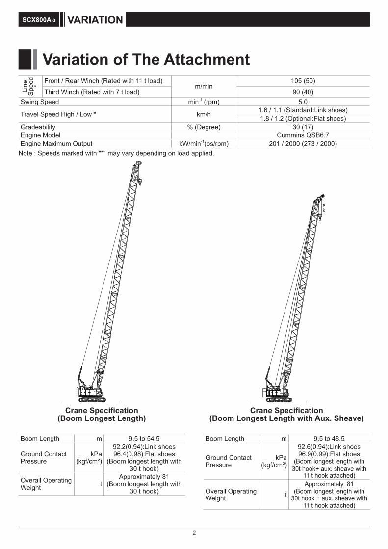
2
Variation of The Attachment
VARIATIONSCX800A-3Li
ne
Spee
d *
Front / Rear Winch (Rated with 11 t load)m/min
105 (50)Third Winch (Rated with 7 t load) 90 (40)
Swing Speed min-1 (rpm) 5.0
Travel Speed High / Low * km/h 1.6 / 1.1 (Standard:Link shoes)1.8 / 1.2 (Optional:Flat shoes)
Gradeability % (Degree) 30 (17)Engine Model Cummins QSB6.7 Engine Maximum Output kW/min-1(ps/rpm) 201 / 2000 (273 / 2000)
Note : Speeds marked with "*" may vary depending on load applied.
Boom Length m 9.5 to 54.5
Ground Contact Pressure
kPa(kgf/cm²)
92.2(0.94):Link shoes96.4(0.98):Flat shoes
(Boom longest length with 30 t hook)
Overall Operating Weight t
Approximately 81(Boom longest length with
30 t hook)
Crane Specification (Boom Longest Length)
Boom Length m 9.5 to 48.5
Ground Contact Pressure
kPa (kgf/cm²)
92.6(0.94):Link shoes96.9(0.99):Flat shoes
(Boom longest length with 30t hook+ aux. sheave with
11 t hook attached)
Overall Operating Weight t
Approximately 81(Boom longest length with
30t hook + aux. sheave with 11 t hook attached)
Crane Specification (Boom Longest Length with Aux. Sheave)

3
VARIATION SCX800A-3
Boom Length m 27.5 to 45.5Crane Jib Length m 9 to 18Boom + Crane Jib Longest Length m 42.5 + 18
Ground Contact Pressure
kPa(kgf/cm²)
93.1(0.95):Link shoes97.4(0.99):Flat shoes
(Boom + crane jib longest length with 30 t + 11 t hook
attached)
Overall Operating Weight t
Approximately 82(Boom + crane jib longest length with 30 t + 11 t hook
attached)
Crane Specification (Boom Longest Length with Crane Jib)
NOTE :Illustration are when standard link shoes and non-cast type weights are installed.

4
Variation of The Attachment 2
Specifications 6
Crane Specifications 8
Dimensions and Specifications ................................................................................................................8Boom and Crane Jib Configurations ........................................................................................................9Combination of Boom and Crane Jib (Offset Angle 10° and 30°) ........................................................12Working Ranges .......................................................................................................................................13
Main Boom ...................................................................................................................................................... 13
Aux. Sheave .................................................................................................................................................... 14
18 m Crane Jib (Offset Angle 10° and 30°) ..................................................................................................... 15
Gross Rated Load Table ..........................................................................................................................16 Main Boom (1/2) ............................................................................................................................................... 16
Main Boom (2/2) ............................................................................................................................................... 17
Aux. Sheave (1/2) .............................................................................................................................................. 18
Aux. Sheave (2/2) .............................................................................................................................................. 19
Main Boom with Aux. Sheave (1/2) ................................................................................................................... 20
Main Boom with Aux. Sheave (2/2) ................................................................................................................... 21
Crane Jib (1/4) .................................................................................................................................................. 22
Crane Jib (2/4) ................................................................................................................................................... 23
Crane Jib (3/4) ................................................................................................................................................... 24
Crane Jib (4/4) ................................................................................................................................................... 25
Main Boom with Crane Jib (1/4) ....................................................................................................................... 26
Main Boom with Crane Jib (2/4) ....................................................................................................................... 27
Main Boom with Crane Jib (3/4) ....................................................................................................................... 28
Main Boom with Crane Jib (4/4) ........................................................................................................................ 29
Clamshell Specifications 30
Dimensions and Specifications ..............................................................................................................30 Working Ranges ................................................................................................................................................ 30
Specifications .................................................................................................................................................... 31
CONTENTSSCX800A-3
VARIATION
SPECIFICATIONS

5
Clamshell Bucket ............................................................................................................................................... 31
Gross Rated Load Table .................................................................................................................................... 31
CONTENTS SCX800A-3
TECHNICAL DATA
Weights and Dimensions of Disassembled Units 32
Weights and Dimensions List .................................................................................................................32
Equipment List 37
Standard and Optional Equipment .........................................................................................................37

6
Specifications
SPECIFICATIONSSCX800A-3
Specifications
Model Cummins QSB6.7
Type 4-cycle, Water-cooled, Direct injection, Turbo-charged, Diesel engine
Displacement 6.7 litersMaximum Output
201 kW / 2,000 min-1
(273 ps / 2,000 rpm)Fuel Tank Capacity 428 liters
Notes Engine meets Stage IV / Tier 4f of engine exhaust gas emission regulations in USA, Europe, and Japan.Engine rated horsepower is based on international rating formula that includes engine alternator and without fan.
Engine
Control System
Main actuators are actuated by main hydraulic system controlled with pilot hydraulic system. Safety devices are securely operated by combined various electronic control with hydraulic system. Working speed can be precisely controlled according to control lever stroke and control dials depending on work.
Control LeversDesigned and positioned based on ergonomics. Arm-chair lever type is standard. Cross operation lever type and front lever type are available as option.
Display Panel Design
8 inches size. Located to check work state easily without disturbing the view of the operator.
Control
Hydraulic Oil Tank Capacity 320 liters
Hydraulic Pump Capacity
Max. 31.4 MPa
P1 280 liters / min
for Front, Rear, boom hoist winch and travel
P2 280 liters / min
for Front, Rear, third winch and travel
P3 160 liters / min
fo r Sw ing , Craw le r side frame retract and Gantry cyl.
P4 41 liters / min
Pilot control, Brake cooling, Reeving tagline, etc.
P5 41 liters / min
P6 41 liters / min
P7 32 liters / min
Hydraulic System
Front and Rear WinchWinch Front RearRope Diameter 26 mm 26 mm
Rope Length
Standard 175 m 150 m for Aux. sheave- 150 m for Crane jib
Winding Capacity 210 m 210 mLine Pull Rated 108 kN 108 kN
Standard EquipmentHigh-speed winching is possible by ECO winch mode with low engine speed under light loads.
Optional Equipment Free fall winch with brake controled by pedal operation.
Boom Hoist WinchRope Diameter 16 mmRope Length Incorporated 150 m
Hydraulic motor with multi-disc brakes.
Winch
Consisted of 1 hydraulic motors with reduction gear and multi-disc brakes and a swing bearing which has inner tooth. Optional swing brake pedal enables operator to control swing precisely.
Swing System
Gantry is welded steel construction. Raised and lowered by power hydraulic cylinders.
Gantry
Third Winch (Optional)Rope Diameter 22.4 mmRope Length
Standard 180 mWinding Capacity 228 m
Line Pull Rated 69 kNFree fal l winch with brake controled by pedal operation.

7
Upper Weight (Standard) :3.4m width non cast
Total Weight 28.2 ton9.2 ton Base Weight (A) 1 piece9.5 ton Weight (B) 2 piece
Upper Weight (Optional) :3.2m width cast
Total Weight 28.2 ton9.2 ton Base Weight (A) 1 piece9.1 ton Insert Weight (B) 1 piece9.9 ton Top Weight (C) 1 piece
Lower Weight :only for optional flat type crawler
Total Weight 4.0 ton
2.0 ton Lower Weight 2 pieces
Counter Weight
Welded steel construction with crawler side frame extend-retract cylinders.
Carbody Frame
Frame Welded steel box construction, and can be retracted.
Shoe Link type 810 mm width shoe each side.
Upper Roller 2 pieces double flange type for each side.
Lower Roller
12 pieces each side.Forging heat treated steel with double flange type.2 plane bearing with floating seal for lifetime lubrication.
Travel Device
1 peace each side.Hydraulic travel device (Hydrayulic motor and reducer)
Travel speed(Gradability : 30%)
High : 1.6 km/h
Low : 1.1 km/h
Crawler Side frame
Specifications
SPECIFICATIONS SCX800A-3
Link type (Standard)
Frame Welded steel box construction, and can be retracted.
Shoe Flat type 800 mm width shoe each side.
Upper Roller 2 pieces double flange type for each side.
Lower Roller
10 pieces each side.Forging heat treated steel with double flange type.2 plane bearing with floating seal for lifetime lubrication.
Travel Device
1 peace each side.Hydraulic travel device (Hydrayulic motor and reducer)
Travel speed(Gradability : 30%)
High : 1.8 km/h
Low : 1.2 km/h
Flat type (Optional)

8
Crane SpecificationsDimensions and Specifications
SPECIFICATIONSSCX800A-3
Dimensions and Specifications
Crane SpecificationsMax. Lifting Load × Working Radius t × m 80×3.4Basic Boom Length m 9.5Max. Boom Length m 54.5Max. Crane Jib Length m 9 to 18Max. Boom + Jib Length m 42.5 + 18
Ground Contact Pressure kPa (kgf/cm²) 87.4 (0.89) (w / Basic Boom, 80 t Hook, Link shoes)93.2 (0.95) (w / Basic Boom, 80 t Hook, Flat shoes)
Overall Operating Weight t Approximately 78.3 (w / Basic Boom, 80 t Hook)
Hook Weight80 t 1050 kg50 t 900 kg30 t 730 kg11 t 370 kg
Crane Specifications
NOTE : Data is expressed in SI units followed by conventional units in ( ).
NOTE : ( ) In case of the flat shoes.
Cast type weight(Optional)
Cast type weight(Optional)
5500
4000
R3980
retracted:3400 (3200)
9500
1100
4840 (4830)5300 (5150)6280 (6060)
5915
470
1150
(990
)
810
3200950
Working Radius
1215
2150
3330
(324
5)
3295
R3980
1905
(800)
(380)
1875
(17
85)
1270
3400
3200

9
Boom and Crane Jib Configurations
BoomBoom Length
(m) Boom Configurations
9.53.2
5.5 4
12.53
33.2
45.5
15.56
63.2
45.5
3
33.2
45.5
3
3
18.5
3
3
6
9
6
9
3.2
3.2
4
4
5.5
5.5
21.5
3.245.5
3 3
3
6
63
3
3
9
93.2
45.5
24.56 9
6 93.2
45.5
3.245.5
3 3
3
9
93
27.5
9
9 or 9B
9 9
9 9 or 9B
3.2
3.2
4
4
5.5
5.5
3
3
6
6
30.53
3
9 9
9 9 or 9B3.2
45.5
9
9 or 9B3.2
45.5
3
3
3
3
6
6
33.56 9 9
6 9 9 or 9B3.2
45.5
9
9 or 9B3.2
45.5
3
3
3
3
9
9
Crane SpecificationsBoom and Crane Jib Configurations
SPECIFICATIONS SCX800A-3
A star mark( ☆ ) indicates manufacture's recommended boom configuration.

10
Crane SpecificationsBoom and Crane Jib Configurations
SPECIFICATIONSSCX800A-3
BoomBoom Length
(m) Boom Configurations
36.5
3 9
3 9 or 9B
6
9
9
9 9
6
9
9
9 9 or 9B
3.2
3.2
4
4
5.5
5.5
39.53
3
9 9 9
9 9 9 or 9B3.2
45.5
3 9
3
3
3 9 or 9B
6 9
6 93.2
45.5
42.56 9 9 9
6 9 9 9 or 9B3.2
45.5
3 9
3
3
3 9 or 9B
9 9
9 93.2
45.5
45.5
3 9
3 9 or 9B
6
9
9
9
9
9 9
6
9
9
9
9
9 9 or 9B
3.2
3.2
4
4
5.5
5.5
48.53
3
9 9 9 9
9 9 9 9 or 9B3.2
45.5
3 9
3
3
3 9 or 9B
6 9 9
6 9 93.2
45.5
51.56 9 9 9 9
6 9 9 9 9 or 9B3.2
45.5
3 9
3
3
3 9 or 9B
9 9 9
9 9 93.2
45.5
54.53 9
3 9 or 9B
6 9 9 9
6 9 9 93.2
45.5
Aux. Sheave Installable Boom LengthBoom Length (m) 9.5 12.5 15.5 18.5 21.5 24.5 27.5 30.5 33.5 36.5 39.5 42.5 45.5 48.5 51.5 54.5With Aux. Sheave × ×
( : Attachable : Not Attachable )
A star mark( ☆ ) indicates manufacture's recommended boom configuration.
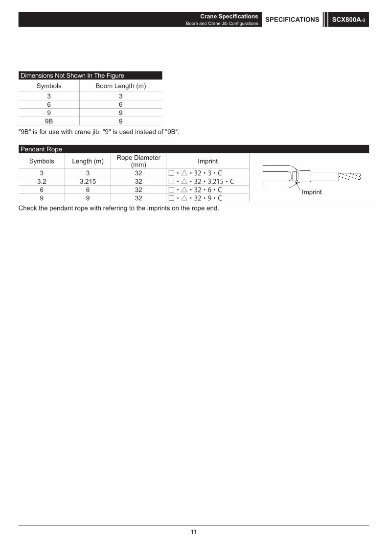
11
Dimensions Not Shown In The FigureSymbols Boom Length (m)
3 36 69 9
9B 9
Pendant Rope
Symbols Length (m) Rope Diameter (mm) Imprint
Imprint
3 3 32 □・△・32・3・C3.2 3.215 32 □・△・32・3.215・C6 6 32 □・△・32・6・C9 9 32 □・△・32・9・C
"9B" is for use with crane jib. "9" is used instead of "9B".
Check the pendant rope with referring to the imprints on the rope end.
Crane SpecificationsBoom and Crane Jib Configurations
SPECIFICATIONS SCX800A-3

12
Crane SpecificationsCombination of Boom and Crane Jib (Offset Angle 10° and 30°)
SPECIFICATIONSSCX800A-3
Jib Pendant Rope
Symbols Length (m) Rope Diameter (mm) Imprint
Imprint
2.9 2.85 20 □・△・20・2.85・C8.5 8.45 20 □・△・20・8.45・C18 18.35 20 □・△・20・18.35・C30 29.5 20 □・△・20・29.5・C
Crane Jib (Offset Angle 10° and 30°)Crane Jib Length
(m) Offset Angle Crane Jib Configurations
9
10°9B 4
30 18
30°
9B4
3018
2.9
13.5
10°9B 4
3018
8.5
30°
9B4
3018
8.5
4.5 4.5 4.52.9
18
10°
9B 4
3018
8.58.5
30°
9B4
30
188.5 8.5 2.9
Dimensions Not Shown In The FigureSymbols Jib Length (m)
4.5 4.5
Combination of Boom and Crane Jib (Offset Angle 10° and 30°)Boom Length (m) 9 12.5 15.5 18.5 21.5 24.5 27.5 30.5 33.5 36.5 39.5 42.5 45.5 48.5 51.5
Jib
Leng
th
(m) 9
13.518
( : Attachable : Not Attachable )
Combination of Boom and Crane Jib (Offset Angle 10° and 30°)
Check the pendant rope with referring to the imprints on the rope end.

13
Working Ranges
Main Boom
80 t Hook
Hei
ght A
bove
Gro
und
(m)
Working Radius (m)
30 t Hook50 t Hook
Crane SpecificationsWorking Ranges
SPECIFICATIONS SCX800A-3
9.5
12.5
15.5
18.5
21.5
24.5
27.5
30.5
33.5
36.5
39.5
42.5
45.5
48.5
51.5
54.5
4.9m
5.1m 4.8m
80°
30°
70° 60° 50°
40°
10 15 20 25 30 35 40 45 50 55
5
10
15
20
25
30
35
40
45
50
55
60
501.1m
1.87
5m1.
785m
(Link
shoe
s)(F
lat sh
oes)

14
Aux. Sheave H
eigh
t Abo
ve G
roun
d (m
)
Working Radius (m)
11t Hook
Crane SpecificationsWorking Ranges
SPECIFICATIONSSCX800A-3
9.5
12.5
15.5
18.5
21.5
24.5
27.5
30.5
33.5
36.5
39.5
42.5
45.5
48.5
3.3m
80° 70° 60° 50°
30°
40°
5 10 15 20 25 30 35 40 45 50 550
5
10
15
20
25
30
35
40
45
50
55
60
1.1m
1.87
5m1.
785m
(Link
shoe
s)(F
lat sh
oes)

15
18 m Crane Jib (Offset Angle 10° and 30°)
Working Radius (m)
Hei
ght A
bove
Gro
und
(m)
11t Hook
Crane SpecificationsWorking Ranges
SPECIFICATIONS SCX800A-3
Offset Angle 30°
Offset Angle 10°
80°
30°
70° 60° 50°
40°
10 15 20 25 30 35 40 45 50 55
5
10
15
20
25
30
35
40
45
50
55
60
501.1m
65
10°
3.3m
27.5
30.5
33.5
36.5
39.5
42.5
30°
1.87
5m1.
785m
(Link
shoe
s)(F
lat sh
oes)

16
Gross Rated Load Table
Main Boom (1/2)
Crane SpecificationsGross Rated Load Table
SPECIFICATIONSSCX800A-3
unit ton
4.3 xm9.3 00.08 4.3 3.5 76.50 70.60t 3.5
4 05.96 00.07 4 5.4 00.26 51.26 03.26 5.4 5 xm6.557.35 00.65 51.65 03.65 5
5.5 51.35 51.20 50.45 48.05 44.90t 6.1mx 6.7mx 5.5 6 46.40 46.30 45.40 43.45 41.55 39.20t 34.05t 7.2mx 6 7 38.65 38.60 37.80 36.35 34.95 33.70 32.50 30.45t 7 8 31.90 31.85 31.80 31.20 30.05 29.10 28.15 27.25 8 9 27.10 27.05 26.95 26.90 26.30 25.55 24.75 24.00 9
10 9.5mx 23.40 23.35 23.30 23.15 22.70 22.05 21.40 10 12 25.20t 18.35 18.25 18.20 18.10 18.05 17.95 17.50 12 14 12.1mx 14.90 14.85 14.70 14.65 14.55 14.45 14 16 18.20t 14.7mx 12.45 12.30 12.25 12.10 12.05 16
00.41 81 t 17.3mx 10.50 10.40 10.30 10.20 18 02.11 02 t 19.9mx 9.00 8.90 8.80 20
22 56.7 08.7 09.7 t51.9 22 42 57.6 58.6 xm5.22 42
56.7 62 t 25.1mx 6.00 26 54.6 82 t 27.7mx 28
54.5 03 t 30
1. The rated loads are determined according to EN13000 rating with the machineon firm level ground.
2. The figures surrounded by bold lines are based on factors other than those which would cause a tipping condition.
3. To calculate the maximum load that can actually be lifted, deduct weight of all lifting accessories, such as boom hook and jib hook, from figures shown above.
4. Working radius is the horizontal distance from the slewing center to the center of gravity of a lifted load.
5. The counter weight is shown in the next table.
6. The relations between the reeving part number of rope and the maximum rated loads is shown in the table next page.
Crawler shoe Upper weight Lower weightLink shoe 28.2 -Flat shoe 28.2 4.0
WorkingRadius
(m) 5.035.125.815.515.215.9
WorkingRadius
(m)
Boom Length ( m )
24.5 27.5

17
Main Boom (2/2)
Crane SpecificationsGross Rated Load Table
SPECIFICATIONS SCX800A-3
unit ton
6 xm8.7 6 7 27.05t 7 xm8.8xm3.8 8 26.35 24.55t 22.10t 8 xm9.9xm4.9 9 23.25 22.55 21.85 19.10t 17.05t 10.5mx 11.0mx 11.6mx 9
10 20.80 20.20 19.55 18.70 17.00 16.70t 13.55t 12.00t 10 12 17.00 16.55 16.05 15.70 15.20 14.45 13.10 11.85 12 14 14.25 13.85 13.45 13.20 12.80 12.45 12.05 11.00 14 16 11.90 11.80 11.50 11.25 10.90 10.60 10.30 9.95 16 18 10.10 10.00 9.85 9.75 9.45 9.15 8.85 8.55 18 20 8.70 8.60 8.45 8.40 8.25 8.00 7.70 7.45 20 22 7.55 7.45 7.30 7.25 7.10 7.00 6.75 6.50 22 24 6.65 6.55 6.40 6.35 6.20 6.10 5.95 5.70 24 26 5.85 5.75 5.60 5.55 5.40 5.30 5.20 5.00 26 28 5.20 5.10 4.95 4.90 4.75 4.65 4.55 4.40 28 30 4.70 4.55 4.40 4.35 4.20 4.10 3.95 3.80 30 32 30.3mx 4.10 3.95 3.85 3.70 3.60 3.50 3.35 32 34 4.60t 32.9mx 3.50 3.45 3.30 3.20 3.05 2.90 34 36 3.90t 35.5mx 3.05 2.90 2.80 2.70 2.55 36
83 02.2 53.2 05.2 06.2 57.2 t52.3 83 04 09.1 50.2 02.2 03.2 xm1.83 04 24 56.1 08.1 59.1 xm7.04t57.2 24 44 04.1 55.1 xm3.34t02.2 44
57.1 64 t 45.9mx 45.0mx 46 84 t03.1 t53.1 84
WorkingRadius
(m)
WorkingRadius
(m)5.455.155.245.935.635.33
Boom Length ( m )
45.5 48.5
The relations between the reeving part number of rope and the maximum rated loadsHook Capacity Hook Weight
( t ) ( t ) 8 falls 7 falls 6 falls 5 falls 4 falls 3 falls 2 falls 1 fall80 1.05 80 77 66 55 4450 0.90 50 4430 0.73 30 2211 0.37 11
Maximum rated loads ( t )

18
Aux. Sheave (1/2)
Crane SpecificationsGross Rated Load Table
SPECIFICATIONSSCX800A-3
unit ton
3.4xm9.4 00.113.4 4.5 11.00 11.00t 5.4xm4.5 5 11.00 11.00 11.00t 5
5.5xm5.600.1100.1100.115.5 6 11.00 11.00 11.00 11.00 11.00t 7.1mx 7.6mx 6 7 11.00 11.00 11.00 11.00 11.00 11.00t 11.00t 7 8 11.00 11.00 11.00 11.00 11.00 11.00 11.00 8 9 11.00 11.00 11.00 11.00 11.00 11.00 11.00 9
10 11.00 11.00 11.00 11.00 11.00 11.00 11.00 10 12 10.8mx 11.00 11.00 11.00 11.00 11.00 11.00 12 14 11.00t 13.4mx 11.00 11.00 11.00 11.00 11.00 14 16 11.00t 11.00 11.00 11.00 11.00 11.00 16
8150.0151.0152.0104.01 81 0206.857.808.8xm6.81 02
59.9 22 t 21.2mx 7.60 7.50 22 01.8 42 t 23.8mx 6.55 24
08.6 62 t 5.80 26 82xm4.62 82
56.5 03 t 30
1. The rated loads are determined according to EN13000 rating with the machineon firm level ground.
2. The figures surrounded by bold lines are based on factors other than those which would cause a tipping condition.
3. To calculate the maximum load that can actually be lifted, deduct weight of all lifting accessories, such as boom hook and jib hook, from figures shown above.
4. Working radius is the horizontal distance from the slewing center to the center of gravity of a lifted load.5. The counter weight is shown in the next table.
6. Hook weight are shown in the table next page.
Link shoe 28.2 -Flat shoe 28.2 4.0
Crawler shoe Upper weight Lower weight
Boom Length ( m )
21.5 24.5 27.5
WorkingRadius
(m)
WorkingRadius
(m)9.5 12.5 15.5 18.5
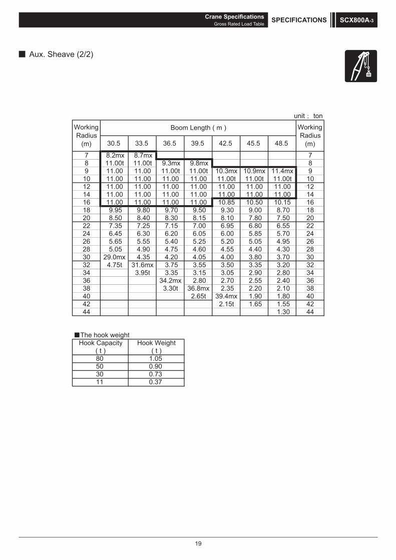
19
Aux. Sheave (2/2)
Crane SpecificationsGross Rated Load Table
SPECIFICATIONS SCX800A-3
unit ton
7xm7.8 xm2.8 7 8 11.00t 11.00t 8xm8.9 xm3.9 9 11.00 11.00 11.00t 11.00t 10.3mx 10.9mx 11.4mx 9
10 11.00 11.00 11.00 11.00 11.00t 11.00t 11.00t 10 12 11.00 11.00 11.00 11.00 11.00 11.00 11.00 12 14 11.00 11.00 11.00 11.00 11.00 11.00 11.00 14 16 11.00 11.00 11.00 11.00 10.85 10.50 10.15 16 18 9.95 9.80 9.70 9.50 9.30 9.00 8.70 18 20 8.50 8.40 8.30 8.15 8.10 7.80 7.50 20 22 7.35 7.25 7.15 7.00 6.95 6.80 6.55 22 24 6.45 6.30 6.20 6.05 6.00 5.85 5.70 24 26 5.65 5.55 5.40 5.25 5.20 5.05 4.95 26 28 5.05 4.90 4.75 4.60 4.55 4.40 4.30 28 30 29.0mx 4.35 4.20 4.05 4.00 3.80 3.70 30 32 4.75t 31.6mx 3.75 3.55 3.50 3.35 3.20 32 34 3.95t 3.35 3.15 3.05 2.90 2.80 34
6304.255.207.208.2 xm2.43 63 03.3 83 t 36.8mx 2.35 2.20 2.10 38
56.2 04 t 39.4mx 1.90 1.80 40 51.2 24 t 1.65 1.55 42
4403.1 44
The hook weight
3011
Hook Weight( t )
1.050.900.730.37
Hook Capacity( t )8050
39.5 42.5 45.5 48.5
Boom Length ( m )
30.5 33.5 36.5
WorkingRadius
(m)
WorkingRadius
(m)

20
Main Boom with Aux. Sheave (1/2)
Crane SpecificationsGross Rated Load Table
SPECIFICATIONSSCX800A-3
unit ton
4.3 xm9.3 00.08 4.3 5.3 t54.0705.67 5.3 457.86 09.86 4 5.402.16 53.16 54.16 5.4 5xm6.502.35 02.55 53.55 54.55 5
5.5 50.50 50.35 49.90 47.50 44.35t 6.1mx 6.7mx 5.5 6 46.30 46.15 44.85 42.90 40.95 38.60t 33.45t 6 7 38.20 38.20 37.25 35.80 34.35 33.15 31.90 7 8 31.45 31.40 31.35 30.65 29.50 28.55 27.55 8 9 26.65 26.60 26.50 26.50 25.75 25.00 24.15 9
10 9.5mx 23.00 22.90 22.85 22.70 22.15 21.45 10 12 24.75t 17.95 17.85 17.80 17.65 17.60 17.40 12 14 12.1mx 14.50 14.40 14.25 14.20 14.10 14 16 17.75t 14.7mx 12.00 11.85 11.80 11.70 16
81 58.90 00.01 50.01 xm3.71t55.31 81 02 54.8 06.8 xm9.91t08.01 02 22 53.7 05.7 t57.8 22 42 54.6 xm5.22 42 62 xm1.52t52.7 62 82 t00.6 82
1. The rated loads are determined according to EN13000 rating with the machineon firm level ground.
2. The figures surrounded by bold lines are based on factors other than those which would cause a tipping condition.
3. To calculate the maximum load that can actually be lifted, deduct weight of all lifting accessories, such as boom hook and jib hook, from figures shown above.
4. Working radius is the horizontal distance from the slewing center to the center of gravity of a lifted load.
5. The counter weight is shown in the next table.
6. The relations between the reeving part number of rope and the maximum rated loads is shown in the table next page.
Flat shoe 28.2 4.0
Crawler shoe Upper weight Lower weightLink shoe 28.2 -
Boom Length ( m )
21.5 24.5 27.5
WorkingRadius
(m)
WorkingRadius
(m)9.5 12.5 15.5 18.5

21
Main Boom with Aux. Sheave (2/2)
Crane SpecificationsGross Rated Load Table
SPECIFICATIONS SCX800A-3
unit ton
6 xm8.7xm2.7 6 7 xm8.8xm3.8t54.62t58.92 7
8 26.65 25.75 23.95t 21.75t 9.4mx 9.9mx 8 9 23.45 22.65 21.95 21.25 19.05t 17.00t 10.5mx 9
10 20.85 20.20 19.55 18.95 18.45 16.95 16.45t 10 12 16.90 16.40 15.90 15.40 15.05 14.55 14.15 12 14 14.00 13.65 13.25 12.85 12.55 12.15 11.80 14 16 11.60 11.45 11.25 10.85 10.65 10.25 9.95 16 18 9.75 9.65 9.55 9.35 9.15 8.80 8.50 18 20 8.35 8.25 8.10 7.95 7.90 7.60 7.35 20 22 7.25 7.10 7.00 6.80 6.75 6.60 6.35 22 24 6.30 6.20 6.05 5.90 5.85 5.70 5.55 24 26 5.55 5.40 5.30 5.15 5.10 4.90 4.80 26 28 27.7mx 4.80 4.65 4.50 4.45 4.25 4.15 28 30 5.00 4.25 4.10 3.95 3.85 3.70 3.60 30 32 30.3mx 3.65 3.45 3.40 3.25 3.10 32 34 4.15t 32.9mx 3.05 3.00 2.80 2.70 34
63 03.2 54.2 06.2 xm5.53t54.3 63 83 00.2 51.2 03.2 t08.2 83 04 07.1 58.1 xm1.83 04 24 54.1 xm7.04t03.2 24 44 xm3.34t57.1 44 64 t03.1 64
Boom Length ( m )
39.5 42.5 45.5 48.530.5 33.5 36.5
WorkingRadius
(m)
WorkingRadius
(m)
The relations between the reeving part number of rope and the maximum rated loadsHook Capacity Hook Weight
( t ) ( t ) 8 falls 7 falls 6 falls 5 falls 4 falls 3 falls 2 falls 1 fall80 1.05 80 77 66 55 4450 0.90 50 4430 0.73 30 2211 0.37 11
Maximum rated loads ( t )
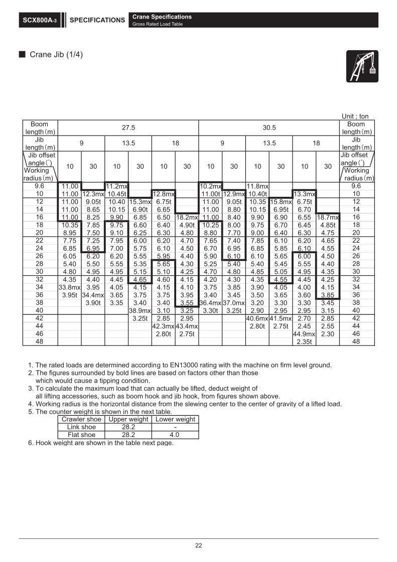
22
Crane Jib (1/4)
Crane SpecificationsGross Rated Load Table
SPECIFICATIONSSCX800A-3
Unit ; tonBoom Boom
length m) length m)Jib Jib
length m) length m) Jib offset
angle ) angle )
xm8.11xm2.01xm2.1100.1111.00 12.3mx 10.45t 12.8mx 11.00t 12.9mx 10.40t 13.3mx11.00 9.05t 10.40 15.3mx 6.75t 11.00 9.05t 10.35 15.8mx 6.75t11.00 8.65 10.15 6.90t 6.65 11.00 8.80 10.15 6.95t 6.7011.00 8.25 9.90 6.85 6.50 18.2mx 11.00 8.40 9.90 6.90 6.55 18.7mx10.35 7.85 9.75 6.60 6.40 4.90t 10.25 8.00 9.75 6.70 6.45 4.85t8.95 7.50 9.10 6.25 6.30 4.80 8.80 7.70 9.00 6.40 6.30 4.757.75 7.25 7.95 6.00 6.20 4.70 7.65 7.40 7.85 6.10 6.20 4.656.85 6.95 7.00 5.75 6.10 4.50 6.70 6.95 6.85 5.85 6.10 4.556.05 6.20 6.20 5.55 5.95 4.40 5.90 6.10 6.10 5.65 6.00 4.505.40 5.50 5.55 5.35 5.65 4.30 5.25 5.40 5.40 5.45 5.55 4.404.80 4.95 4.95 5.15 5.10 4.25 4.70 4.80 4.85 5.05 4.95 4.354.35 4.40 4.45 4.65 4.60 4.15 4.20 4.30 4.35 4.55 4.45 4.25
33.8mx 3.95 4.05 4.15 4.15 4.10 3.75 3.85 3.90 4.05 4.00 4.153.95t 34.4mx 3.65 3.75 3.75 3.95 3.40 3.45 3.50 3.65 3.60 3.85
3.90t 3.35 3.40 3.40 3.55 36.4mx 37.0mx 3.20 3.30 3.30 3.4538.9mx 3.10 3.25 3.30t 3.25t 2.90 2.95 2.95 3.153.25t 2.85 2.95 40.6mx 41.5mx 2.70 2.85
42.3mx 43.4mx 2.80t 2.75t 2.45 2.5503.2xm9.44t57.2t08.2
2.35t
1. The rated loads are determined according to EN13000 rating with the machine on firm level ground. 2. The figures surrounded by bold lines are based on factors other than those which would cause a tipping condition.3. To calculate the maximum load that can actually be lifted, deduct weight of all lifting accessories, such as boom hook and jib hook, from figures shown above.4. Working radius is the horizontal distance from the slewing center to the center of gravity of a lifted load.5. The counter weight is shown in the next table.
6. Hook weight are shown in the table next page.
Crawler shoe Upper weight Lower weightLink shoe 28.2 -
radius m)radius m) Working 30 10 10
9 13.5 18 9 13.5 18
30
9.610
30 10 30 1030 10
40
121416182022
48
44
40
4446
2426283032
141618
42
32343638
34
38
20
36
42
2224262830
4648
5.035.72
Working
9.61012
Jib offset
0301
Flat shoe 28.2 4.0

23
Crane Jib (2/4)
Crane SpecificationsGross Rated Load Table
SPECIFICATIONS SCX800A-3
Unit ; tonBoom Boom
length m) length m)Jib Jib
length m) length m) Jib offset
angle ) angle )
xm3.11xm7.0111.00t 13.4mx 12.3mx 13.9mx 11.00t 12.9mx11.00 9.00t 10.35t 6.70t 11.00 10.35t 14.4mx11.00 8.90 10.15 16.3mx 6.70 11.00 9.00 10.15 16.9mx 6.70t11.00 8.50 9.90 6.90t 6.60 19.3mx 11.00 8.60 9.90 6.80t 6.60 19.8mx10.00 8.15 9.75 6.75 6.50 4.85t 9.70 8.25 9.70 6.75 6.50 4.90t8.65 7.85 8.80 6.50 6.35 4.80 8.50 7.95 8.50 6.55 6.40 4.907.50 7.55 7.70 6.20 6.25 4.70 7.40 7.65 7.50 6.30 6.30 4.756.55 6.80 6.75 6.00 6.15 4.60 6.45 6.70 6.60 6.10 6.25 4.605.75 6.00 5.95 5.75 6.05 4.50 5.65 5.90 5.80 5.85 5.95 4.505.10 5.30 5.25 5.55 5.40 4.40 5.00 5.20 5.15 5.45 5.25 4.454.55 4.70 4.70 4.95 4.80 4.35 4.40 4.60 4.55 4.85 4.70 4.354.05 4.20 4.20 4.40 4.30 4.30 3.90 4.05 4.05 4.30 4.20 4.303.60 3.70 3.75 3.95 3.85 4.15 3.50 3.60 3.60 3.85 3.75 4.053.25 3.30 3.35 3.55 3.50 3.75 3.10 3.20 3.25 3.45 3.35 3.652.90 2.95 3.05 3.15 3.15 3.35 2.80 2.85 2.90 3.05 3.00 3.25
39.0mx 39.6mx 2.75 2.85 2.85 3.00 2.50 2.55 2.60 2.75 2.70 2.902.75t 2.70t 2.45 2.55 2.55 2.70 41.6mx 2.25 2.35 2.45 2.40 2.60
43.2mx 2.30 2.30 2.45 2.25t 42.2mx 2.10 2.15 2.15 2.352.30t 44.1mx 2.10 2.20 2.25t 45.8mx 1.95 1.95 2.10
2.25t 47.5mx 1.95 1.90t 46.7mx 1.75 1.8556.155.1t58.1xm6.84t59.1
xm2.15xm1.05t09.11.55t 1.50t
The hook weight
11 0.3730 0.73
Workingradius m)
8050
Hook Weight( t )
1.050.90
Hook Capacity( t )
radius m)
36.533.5
9
10 30 10 30 10
13.5 18
10 3010 30
4042
9
22
13.5 18
4648
34
16
91012
44
26283032
910
3836
34
30 10 30
20
24
14
18
121416182022
525254
50
54
3638404244
4850
46
2426283032
Working
Jib offset

24
Crane Jib (3/4)
Crane SpecificationsGross Rated Load Table
SPECIFICATIONSSCX800A-3
Unit ; tonBoom Boom
length m) length m)Jib Jib
length m) length m) Jib offset
angle ) angle )
11.8mxxm9.31xm4.21xm4.31t00.11
11.00 14.5mx 10.30t 15.0mx 11.00t 15.1mx 9.85t 15.5mx11.00 8.95t 10.15 17.4mx 6.70t 10.90 8.95t 9.80 6.70t10.85 8.70 9.90 6.90t 6.65 10.55 8.80 9.50 6.659.40 8.40 9.40 6.85 6.50 20.4mx 9.15 8.50 9.15 6.85 6.50 20.9mx8.20 8.05 8.20 6.65 6.40 4.85t 8.00 8.20 8.00 6.70 6.45 4.80t7.20 7.55 7.25 6.40 6.30 4.75 7.00 7.35 7.05 6.50 6.35 4.756.25 6.55 6.40 6.15 6.20 4.65 6.20 6.50 6.25 6.25 6.25 4.655.50 5.75 5.65 5.95 5.75 4.60 5.40 5.70 5.55 5.95 5.55 4.604.80 5.05 5.00 5.35 5.10 4.55 4.75 5.00 4.90 5.30 4.95 4.504.25 4.45 4.40 4.70 4.55 4.45 4.15 4.40 4.30 4.65 4.45 4.403.75 3.90 3.90 4.20 4.00 4.35 3.65 3.85 3.80 4.10 3.95 4.353.30 3.45 3.45 3.70 3.60 3.95 3.25 3.40 3.40 3.65 3.50 3.852.95 3.05 3.10 3.30 3.20 3.50 2.85 3.00 3.00 3.25 3.10 3.452.60 2.70 2.75 2.95 2.85 3.10 2.50 2.65 2.65 2.85 2.75 3.052.30 2.40 2.45 2.60 2.55 2.80 2.20 2.30 2.35 2.55 2.45 2.702.05 2.10 2.15 2.30 2.25 2.50 1.95 2.05 2.05 2.25 2.15 2.401.80 1.85 1.90 2.05 2.00 2.20 1.70 1.75 1.80 1.95 1.90 2.15
44.2mx 44.8mx 1.70 1.80 1.80 1.95 1.50 1.55 1.60 1.70 1.70 1.901.80t 1.75t 1.50 1.55 1.60 1.70 46.8mx 47.4mx 1.40 1.50 1.50 1.65
48.4mx 49.3mx 1.40 1.50 1.40t 1.40t 49.0mx 1.30 1.30 1.451.45t 1.45t 51.3mx 1.30 1.30t 51.5mx
t03.1t03.1
1. The rated loads are determined according to EN13000 rating with the machine on firm level ground. 2. The figures surrounded by bold lines are based on factors other than those which would cause a tipping condition.3. To calculate the maximum load that can actually be lifted, deduct weight of all lifting accessories, such as boom hook and jib hook, from figures shown above.4. Working radius is the horizontal distance from the slewing center to the center of gravity of a lifted load.5. The counter weight is shown in the next table.
6. Hook weight are shown in the table next page. Flat shoe 28.2 4.0
Crawler shoe Upper weight Lower weightLink shoe 28.2 -
Workingradius m)
52 5254 54
46 4648 4850 50
40 4042 4244 44
34 3436 3638 38
28 2830 3032 32
22 2224 2426 26
16 1618 1820 20
10 1012 1214 14
10 30 10 30
9 9
03010301
5.245.93
9 13.5 18 9 13.5 18
10
Jib offset
radius m)
10 3030 Working

25
Crane Jib (4/4)
Crane SpecificationsGross Rated Load Table
SPECIFICATIONS SCX800A-3
Unit ; tonBoom Boom
length m) length m) biJ biJ
length m) length m) Jib offset
angle ) angle )
12.9mx10.00t 15.6mx9.80 8.95t9.40 8.908.85 8.557.70 8.106.70 7.105.90 6.255.20 5.504.60 4.854.00 4.253.50 3.703.05 3.252.70 2.852.35 2.502.05 2.151.80 1.551.55 1.601.30 1.40
46.8mx1.30t
radius m) Working
radius m)
45.5
9
01012121
10 30
414161618181020222224242
36
626282820303
3804042424
23234343
36
0505
444464648484
38
Jib offset
Working
The hook weight
11 0.3730 0.73
8050
Hook Weight( t )
1.050.90
Hook Capacity( t )

26
Main Boom with Crane Jib (1/4)
Crane SpecificationsGross Rated Load Table
SPECIFICATIONSSCX800A-3
Unit ; tonBoom Boom
length m) length m)Jib Jib
length m) length m) Jib offset
angle ) angle )
32.75 32.45 32.25 31.75 31.75 31.00 7.2mx 7.2mx 7.2mx 7.2mx 7.2mx 7.2mx31.15 30.90 30.70 30.25 30.20 29.50 29.15t 28.90t 28.70t 28.25t 28.25t 27.55t26.80 26.60 26.35 25.95 25.85 25.30 25.95 25.70 25.50 25.10 25.05 24.4523.45 23.20 23.00 22.65 22.50 22.00 22.70 22.50 22.30 21.95 21.85 21.3020.70 20.55 20.30 20.00 19.80 19.40 20.10 19.95 19.70 19.40 19.25 18.8016.65 16.50 16.25 16.00 15.80 15.45 16.20 16.05 15.80 15.55 15.35 15.0013.45 13.35 13.10 12.90 12.70 12.40 13.40 13.25 13.00 12.80 12.55 12.3011.05 10.95 10.70 10.55 10.30 10.10 10.95 10.85 10.60 10.45 10.25 10.009.20 9.15 8.90 8.80 8.50 8.35 9.15 9.05 8.80 8.70 8.45 8.257.80 7.80 7.50 7.40 7.15 7.00 7.75 7.65 7.40 7.30 7.05 6.906.70 6.70 6.40 6.35 6.05 5.95 6.60 6.55 6.30 6.20 5.95 5.855.80 5.80 5.50 5.45 5.15 5.10 5.70 5.65 5.40 5.35 5.05 5.00
25.1mx 25.1mx 25.1mx 25.1mx 25.1mx 25.1mx 4.95 4.90 4.65 4.60 4.30 4.305.40t 5.40t 5.10t 5.05t 4.75t 4.70t 27.7mx 27.7mx 27.7mx 27.7mx 27.7mx 27.7mx
4.40t 4.40t 4.10t 4.10t 3.80t 3.75t
1. The rated loads are determined according to EN13000 rating with the machine on firm level ground.2. To calculate the maximum load that can actually be lifted, deduct weight of
all lifting accessories, such as boom hook and jib hook, from figures shown above.3. Working radius is the horizontal distance from the slewing center to the center of gravity of a lifted load. 4. The counter weight is shown in the next table.
5. The relations between the reeving part number of rope and the maximum rated loads is shown in the table next page.
28.2 4.0Link shoeFlat shoe
radius m) Working
radius m)
30 30
26 2624 24
28 28
22 22
16 16
20 2018 18
14 1412 1210 10
6.77 7
9 98 8
6.7
Crawler shoe Upper weight Lower weight
10 30 10 30 10 30 10
9 13.5 18 9 13.5 18
5.035.72
30
Jib offset
30
28.2 -
10 30 10 Working

27
Main Boom with Crane Jib (2/4)
Crane SpecificationsGross Rated Load Table
SPECIFICATIONS SCX800A-3
Unit ; tonBoom Boom
length m) length m)Jib Jib
length m) length m) Jib offset
angle ) angle )
7.8mx 7.8mx 7.8mx 7.8mx 7.8mx 7.8mx25.75t 25.50t 25.35t 24.95t 24.90t 24.25t 8.3mx 8.3mx 8.3mx 8.3mx 8.3mx 8.3mx25.05 24.80 24.65 24.25 24.20 23.60 23.25t 23.05t 22.85t 22.50t 22.45t 21.85t22.00 21.75 21.55 21.20 21.10 20.60 21.30 21.05 20.90 20.55 20.45 19.9519.50 19.30 19.10 18.75 18.65 18.20 18.90 18.70 18.50 18.20 18.10 17.6015.70 15.55 15.30 15.05 14.90 14.55 15.25 15.10 14.85 14.60 14.45 14.1012.95 12.85 12.60 12.40 12.20 11.90 12.60 12.45 12.20 12.00 11.85 11.5510.85 10.75 10.50 10.35 10.15 9.90 10.55 10.45 10.20 10.05 9.85 9.609.05 8.95 8.70 8.55 8.35 8.15 8.95 8.85 8.60 8.45 8.25 8.057.60 7.55 7.30 7.20 6.95 6.80 7.50 7.45 7.20 7.10 6.90 6.706.50 6.45 6.20 6.10 5.85 5.75 6.40 6.35 6.10 6.00 5.75 5.655.55 5.55 5.25 5.20 4.95 4.85 5.45 5.40 5.15 5.10 4.85 4.754.80 4.80 4.50 4.50 4.20 4.15 4.70 4.65 4.40 4.35 4.10 4.004.20 4.15 3.90 3.85 3.60 3.55 4.05 4.05 3.80 3.75 3.50 3.403.65 3.65 3.35 3.35 3.05 3.05 3.50 3.50 3.25 3.20 2.95 2.90
30.3mx 30.3mx 30.3mx 30.3mx 30.3mx 30.3mx 3.05 3.05 2.80 2.75 2.50 2.453.55t 3.55t 3.30t 3.30t 3.00t 2.95t 32.9mx 32.9mx 32.9mx 32.9mx 32.9mx 32.9mx
2.85t 2.85t 2.60t 2.60t 2.30t 2.30t
The relations between the reeving part number of rope and the maximum rated loads
4 falls 3 falls 2 falls 1 fall4444
30 221111
Hook Weight( t )1.050.900.730.37
( t )805030
radius m) Working
radius m)
34 343636
32 3230 3028 2826 2624 24
20 2018 18
22 22
16 16
12 1214 14
9 98 8
10 10
7 76 6
10 30
Jib offset
Working10 30 10 30 10 3030 10 30
Hook Capacity Maximum rated loads ( t )
815.319819
5.635.33
13.5
10

28
Main Boom with Crane Jib (3/4)
Crane SpecificationsGross Rated Load Table
SPECIFICATIONSSCX800A-3
Unit ; tonBoom Boom
length m) length m)Jib Jib
length m) length m) Jib offset
angle ) angle )
8.8mx 8.8mx 8.8mx 8.8mx 8.8mx 8.8mx20.65t 20.60t 20.20t 20.05t 19.70t 19.50t 9.4mx 9.4mx 9.4mx 9.4mx 9.4mx 9.4mx20.50 20.35 20.10 19.80 19.60 19.25 17.70t 17.60t 17.25t 17.10t 16.80t 16.55t18.25 18.05 17.90 17.55 17.50 17.00 17.35 17.25 16.95 16.80 16.45 16.2514.75 14.60 14.35 14.10 14.00 13.60 14.40 14.25 14.05 13.80 13.65 13.2512.15 12.05 11.80 11.60 11.40 11.10 11.90 11.75 11.55 11.35 11.15 10.8510.20 10.10 9.85 9.70 9.50 9.25 9.95 9.85 9.65 9.45 9.25 9.008.65 8.55 8.30 8.15 7.95 7.75 8.45 8.35 8.15 8.00 7.75 7.557.35 7.30 7.05 6.95 6.70 6.55 7.25 7.15 6.90 6.80 6.55 6.406.25 6.15 5.95 5.85 5.65 5.50 6.20 6.10 5.90 5.80 5.55 5.405.30 5.25 5.00 4.95 4.70 4.60 5.25 5.20 5.00 4.90 4.70 4.554.55 4.50 4.25 4.20 3.95 3.85 4.50 4.45 4.20 4.15 3.90 3.803.90 3.85 3.65 3.55 3.35 3.25 3.85 3.80 3.55 3.50 3.30 3.203.35 3.35 3.10 3.05 2.80 2.75 3.30 3.25 3.00 3.00 2.75 2.652.90 2.85 2.60 2.60 2.35 2.30 2.80 2.80 2.55 2.50 2.25 2.202.50 2.50 2.20 2.20 1.95 1.90 2.40 2.40 2.15 2.10 1.85 1.80
35.5mx 35.5mx 35.5mx 35.5mx 35.5mx 35.5mx 2.05 2.05 1.80 1.75 1.50 1.502.20t 2.20t 1.95t 1.95t 1.65t 1.65t 1.75 1.70 1.45 1.45 37.3mx 37.3mx
38.1mx 38.1mx 38.1mx 38.1mx 1.30t 1.30t1.70t 1.70t 1.45t 1.45t
1. The rated loads are determined according to EN13000 rating with the machine on firm level ground.2. To calculate the maximum load that can actually be lifted, deduct weight of
all lifting accessories, such as boom hook and jib hook, from figures shown above.3. Working radius is the horizontal distance from the slewing center to the center of gravity of a lifted load. 4. The counter weight is shown in the next table.
5. The relations between the reeving part number of rope and the maximum rated loads is shown in the table next page.
Lower weightLink shoe 28.2 -Flat shoe 28.2 4.0
Crawler shoe Upper weight
radius m)radius m)
42 4240 4038 3836 3634 34
30 3028 28
32 32
26 26
22 2220 20
24 24
18 18
12 1214 1416 16
10 10
89 987 7
10 30 10 30
Jib offset
30 10 30 10 30 Working Working
9 13.5
5.245.93
18 9 13.5 18
1010 30
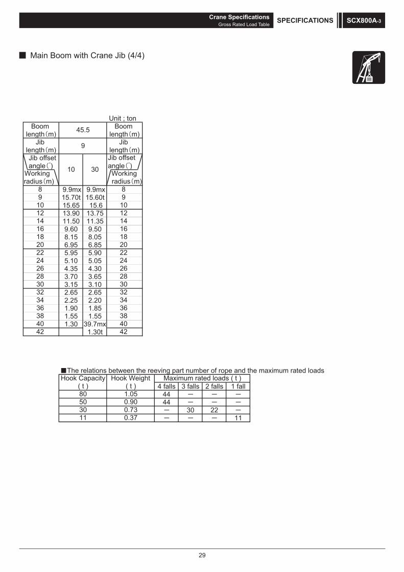
29
Main Boom with Crane Jib (4/4)
Crane SpecificationsGross Rated Load Table
SPECIFICATIONS SCX800A-3
Unit ; tonBoom Boom
length m) length m) biJ biJ
length m) length m) Jib offset
angle ) angle )
9.9mx 9.9mx15.70t 15.60t15.65 15.613.90 13.7511.50 11.359.60 9.508.15 8.056.95 6.855.95 5.905.10 5.054.35 4.303.70 3.653.15 3.102.65 2.652.25 2.201.90 1.851.55 1.551.30 39.7mx
1.30t
radius m) Working
radius m)
838304042424
43436363
03032323
62628282
22220202
4242
8181
41416161
01012121
8899
10 30
9
45.5
Jib offset
Working
The relations between the reeving part number of rope and the maximum rated loads
4 falls 3 falls 2 falls 1 fall4444
30 221111
Hook Weight( t )1.050.900.730.37
( t )805030
Hook Capacity Maximum rated loads ( t )

30
Clamshell SpecificationsDimensions and Specifications
Boom Length m 9.5 12.5 15.5Boom Angle ° 39 45 55 65 35 45 55 65 35 45 55 65Working Radius m 9.1 8.5 7.2 5.9 11.8 10.6 9.0 7.1 14.3 12.7 10.7 8.3Gross Rated Load t 10 10 10 10 10 10 10 10 10 10 10 10Lift L (D + H2) m 36.0 36.8 37.9 38.8 37.2 38.9 40.4 41.6 38.9 41.1 42.9 44.3Max. Digging Depth D m 36
Bucket DumpingHeight H2 m 0.0 0.8 1.9 2.8 1.2 2.9 4.4 5.6 2.9 5.1 6.9 8.3
Working Ranges
Boom Length m 18.5 21.5Boom Angle ° 35 45 55 65 35 45 55 65Working Radius m 16.7 14.8 12.4 9.6 19.2 16.9 14.1 11.0Gross Rated Load t 10 10 10 10 8.65 10 10 10Lift L (D + H2) m 40.6 43.2 45.3 47.0 42.4 45.3 47.8 49.7Max. Digging Depth D m 36
Bucket DumpingHeight H2 m 4.6 7.2 9.3 11.0 6.4 9.3 11.8 13.7
Cast type weight(Optional)
DWorking Radius
1400
H
H1
AC
LH2
1905
1270
2150
1215
(1125
)
5915
(582
5)
(1185
)
6280 (6060)
1875
(1785
)
R3980
1100
NOTE : ( ) In case of the flat shoes.
Clamshell SpecificationsDimensions and Specifications
SPECIFICATIONSSCX800A-3

31
Clamshell SpecificationsBucket Capacity m3 2.5Allowed Maximum Gross Weight for Clamshell Bucket and Captured Load Combined t 10
Boom Length m 9.5 to 21.5Maximum Digging Depth m 36Support Wire Rope Speed * m/min 105 Wire Rope Diameter 26 mmOpening/Closing Wire Rope Speed * m/min 105Boom Hoist Drum Wire Rope Speed (Raise) * m/min 67 Wire Rope Diameter 16.0 mmBoom Hoist Drum Wire Rope Speed (Lower) * m/min 67
Ground Contact Pressure kPa (kgf/cm²)
93.1 (0.95)(w/ Basic Boom, 2.5 m3 Clamshell Bucket, Link shoes)
99.1 (1.01)(w/ Basic Boom, 2.5 m3 Clamshell Bucket, Flat shoes)
Overall Operating Weight t Approximately 83.3(w/ Basic Boom, 2.5 m3 Clamshell Bucket)
NOTE : •Speeds marked with "*" may vary depending on load applied. •SI units are used for specifications. In parenthesis, conventional units are also indicated. •Specifications other than those shown above are the same as those shown in the crane specifications section.
Capacity ( m3 ) Weight ( t ) C (mm) H (mm) H1 (mm)2.5 5.5 3,630 4,180 5,130
Specifications
Gross Rated Load Table
Clamshell Bucket
Clamshell SpecificationsDimensions and Specifications
SPECIFICATIONS SCX800A-3
unit ton
5.9 10.00 6 10.00 7.1mx 7 10.00 10.00t 8.3mx 8 10.00 10.00 10.00t 9.6mx 9 10.00 10.00 10.00 10.00t 11.0mx 10 9.1mx 10.00 10.00 10.00 10.00t 12 10.00t 10.00 10.00 10.00 10.00 14 11.8mx 10.00 10.00 10.00 16 10.00t 14.3mx 10.00 10.00
54.9xm7.61t00.01 81 xm2.91t00.01 02
t56.8 22 1. Max. clamshell rating is 10.0 t.2. Mass of bucket plus load should not exceed clamshell ratings
shown above. Following data are for a general digging application buckets.2.0m3 2.5m3
4.5t 5.5t3. In case of clamshell application, a 9.5 m boom is recomenned as
minimum length of boom, and max. boom length shall not exceed 21.5 m.4. Apparent specific gravity of lifting material :
Earth ........... 1.7 to 1.8 t/m3
Gravel .......... 1.8 to 2.0 t/m3
5. The counter weight is shown in the next table.
6. Max. digging depth below ground shall be 36 m.
28.228.2
Lower weight-
4.0
Bucket capacityBucket mass
Boom Length ( m )WorkingRadius
(m)
Crawler shoeLink shoeFlat shoe
Upper weight
9.5 12.5 15.5 18.5 21.5

32
Description Qty Dimensions (mm) Weight (kg)
MachineryWith boom base
With front winch wire ropeWith boom hoist drum wire rope
With crawlerWith upper spreader
With lower weight
1
NOTE : ( ) In case of the flat shoes.
45900(46100)
MachineryWith front winch wire rope
With boom hoist drum wire ropeWith crawler
With upper spreaderWith lower weight
1
NOTE : ( ) In case of the flat shoes.
44700(44900)
MachineryWith boom base
With front winch wire ropeWith boom hoist drum wire rope
With upper spreader
1
11500
22104410
2810
3200
26800
MachineryWith front winch wire rope
With boom hoist drum wire ropeWith upper spreader
1
7200
22104410
2800
3200
25300
Crawler side frame (ASSY) 26280 (6060)
1075(1050)
810(800)
1150
(990
)
NOTE : ( ) In case of the flat shoes.
8400(7600)
Weights and Dimensions of Disassembled UnitsWeights and Dimensions List
Weights and Dimensions of Disassembled UnitsWeights and Dimensions ListTECHNICAL DATASCX800A-3
11500
3400(3200)
6280(6060)
3290
(320
0)
3400(3200)
6280(6060)
3290
(320
0)
7750
Weights and Dimensions of Disassembled Units
Comply with the regulations when transporting."Weight" refers to the mass of each single unit.
・With upper house handrails, the weight of the main unit increases by 100 kg.・With catwalks, the weight of the main unit increases by 215 kg and the width of the main unit increases by 210 mm.

33
Weights and Dimensions of Disassembled UnitsDescription Qty Dimensions (mm) Weight (kg)
Counter weight (A):Standard 1
960
825
3400
9200
Counter weight (B):Standard 2
960
860
3400
9500
Counter weight (A):Optional 1
3200
745
970
9200
Counter weight (B):Optional 1
3200
960
690
9100
Counter weight (C):Optional 1
3200
960
827
9900
Weights and Dimensions of Disassembled UnitsWeights and Dimensions List TECHNICAL DATA SCX800A-3

34
Weights and Dimensions of Disassembled UnitsDescription Qty Dimensions (mm) Weight (kg)
Lower weight :In case of the flat shoes 2
1400 430
937 2020
Upper spreader 1
1706 333
765
285
Boom base (5.5)With connector pin
With exclusive crane backstop1
1670
5690
1720 1230
Boom top (4)With pendant rope 1
44201500
1800 1340
3 m boom insert (3)With connector pin
Without pendant rope1
31201500
1610
325
6 m boom insert (6)With connector pin
Without pendant rope1
61201500
1610
545
9 m boom insert (9)With connector pin
Without pendant rope1
91201500
1610 750
9 m special boom insert (9B)(crane jib combined use boom)
With connector pinWithout pendant rope
1
91201500
1630 755
Crane jib bottom (4.5)With connector pin
With jib strut1
4615850
860
490
Weights and Dimensions of Disassembled UnitsWeights and Dimensions ListTECHNICAL DATASCX800A-3
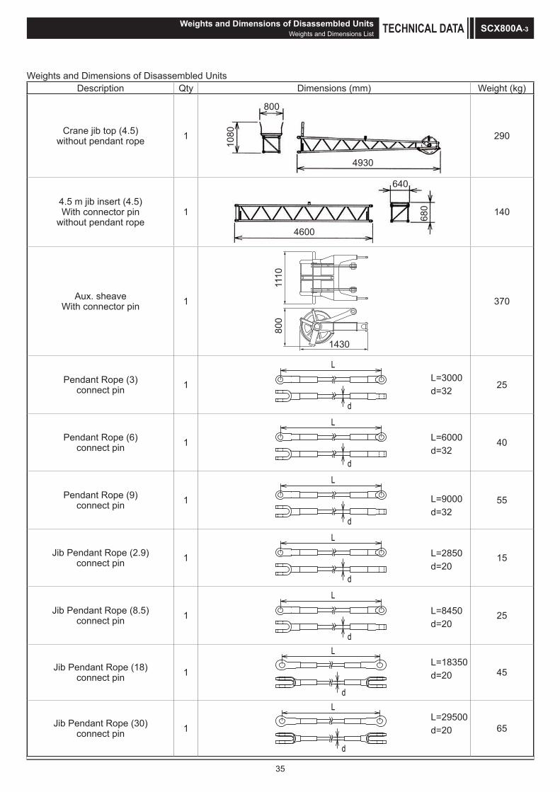
35
Weights and Dimensions of Disassembled UnitsDescription Qty Dimensions (mm) Weight (kg)
Crane jib top (4.5)without pendant rope 1
800
1080
4930
290
4.5 m jib insert (4.5)With connector pin
without pendant rope1 68
0
4600
640
140
Aux. sheaveWith connector pin 1
1110
800
1430
370
Pendant Rope (3)connect pin 1
L
d
25
Pendant Rope (6)connect pin 1
L
d
40
Pendant Rope (9)connect pin 1
L
d
55
Jib Pendant Rope (2.9)connect pin 1
L
d
15
Jib Pendant Rope (8.5)connect pin 1
L
d
25
Jib Pendant Rope (18)connect pin 1
L
d
45
Jib Pendant Rope (30)connect pin 1
L
d
65
L=3000d=32
L=6000d=32
L=9000d=32
L=2850d=20
Weights and Dimensions of Disassembled UnitsWeights and Dimensions List TECHNICAL DATA SCX800A-3
L=8450d=20
L=18350d=20
L=29500d=20

36
Weights and Dimensions of Disassembled UnitsDescription Qty Dimensions (mm) Weight (kg)
80 t hook 1 tKg
Hitachi Sumitomo Heavy IndustriesConstruction Crane Co.,Ltd.
MADE IN JAPAN
780
2110
480
1050
50 t hook 1
790 495
1930
900
30t hook 1
1806
790 394
730
11t hook 1
450450
1030 370
Weights and Dimensions of Disassembled UnitsWeights and Dimensions ListTECHNICAL DATASCX800A-3

37
Equipment List Standard and Optional Equipment
: Standard : Optional : No setting
Item* are described in the last page of this list. Crane Clamshell
Lower
Structure
810 mm Crawler Shoe (Link shoes)800 mm Crawler Shoe (Flat shoes)Jack Up UnitCrawler Extension / Retraction System Steps Shoe Tension Unit *1 *1
Upper
Structure
Free-fall Assist SystemCab Up / Down Catwalk Under Cover (Bed Lower Surface) Working Light (× 2)Back Mirror (Left / Right)Gantry CylindersCentral Lubrication Unit (for Turntable Bearing) Drum Flange Cover Auto Idle StopEco WinchDrum MirrorDrum Light Winch Rope Retainer (Front Winch) Winch Rope Retainer (Rear Winch) Catwalk (Folding Type, Left / Right) Catwalk with Handrails (Folding Type, Left / Right) / *2 / *2
3400mm Width Counter Weight (Non-Cast Type)3200mm Width Counter Weight (Cast Type)Electric Fuel Pump Handrails (Folding Type)Winch with Front and Rear Free MechanismThird Winch (Rope not Included)
Cab
Air ConditionerSunvisorSunshadeWiper with Washer (Front Window, Cab Roof Window) Microphone & Loud-speakerAM / FM Radio (with Clock)Room LampCup Holder24 V Power Socket (× 2) Floor CarpetLevel Gauge (in Cab)Accelerator Pedal (Right Side)Arm Chair LeverCross Operation Lever (Lever Lock not Attached) / *2 / *2
Front Operation Lever (with Lever Lock) Standard SeatSeat with Suspension / *2 / *2
Travel Operation Pedal (Cannot be installed when winch with free mechanism attached)
Equipment List Standard and Optional Equipment TECHNICAL DATA SCX800A-3

38
: Standard : Optional : No settingItem
* are described in the last page of this list. Crane Clamshell
Cab
Boom Hoist Operation Pedal *3
Swing Brake Operation Pedal *3
FanFront / Rear Operation Lever, Brake Pedal PermutationFuel Burning HeaterAccelerator GripDrum Rotation Sensor (Front / Rear / Boom Hoist) *4
Speed Control Dial (Front / Rear/Boom Hoist / Swing)Life Hanmer
Attachment
9.5 m Basic Boom (Boom Base: 5.5 m, Boom Top: 4 m) 3 m Boom Insert 6 m Boom Insert9 m Boom Insert9 m Special Boom Insert (9B)Parts Set for 9 m Crane Jib [9 m Basic Jib, Anti-two Block, Jib Mast] 4.5 m Crane Jib InsertParts Set for Auxiliary Sheave [Auxiliary Sheave, Auxiliary Sheave Anti-two Block] 80 t Hook (4 Sheaves)50 t Hook (2 Sheaves)30 t Hook (1 Sheave)11 t Hook
Wire
Rope
Front Winch ( 26)Mono Rope EP 3 × F (40)IWRC 6 × WS (31)IWRC 6 × Fi (25) *5
Rear Winch ( 26)Mono Rope EP 3 × F (40)IWRC 6 × WS (31)IWRC 6 × Fi (25) *6
Third Winch ( 22.4) XP IWRC 6 × WS (31)Boom Hoist Winch ( 16) IWRC 6 × P WS (31)
Safety
Device
Moment Limiter3 Color Percentage Indicator Light / *7 / *7
Gate Lock LeverIndividual Operation Lever Lock (Front, Rear, Boom Hoist, Travel) *8
Automatic Drum Lock (Boom Hoist)Winch Drum Lock (Front/Rear)Lowering Limiter (Winch Drum Dead Turns Detective Device) / *7 / *7
Swing LockSwing AlarmTravel AlarmAuto Slowdown (Slow Stop) Boom Hoist Limiting DeviceSecondary Boom Over Hoist Prevent DeviceWarning AlarmMonitor Panel (Machine Monitoring) Engine Start Interlock SystemEmergency Engine Stop Switch (In cab) Lifting Height Indication DeviceAnti-two Block DeviceMoment Limiter (M/L) Mode Selector (In Right House) / *7
Swing Neutral Free / Brake Selection SwitchSwing Restriction Unit Anemometer
Equipment List Standard and Optional EquipmentTECHNICAL DATASCX800A-3

39
: Standard : Optional : No setting Item
* are described in the last page of this list. Crane Clamshell
Safety
Device
Obstacle Lights (Fixed lights) Drum and Rear View Monitor System (3 Cameras) Cab Roof Window Guard / *7 / *7
Common
Parts
Boom Back StopBoom Angle SensorBoom Lifting Piece Counter Weight with Self Assembly Unit *9
Remote Sensing (Mobile Communication Terminal, Data Logging Device)Skywalk (with Stanchion)Skywalk (without Stanchion)Boom Top Under Surface Buffer (Protector) Load Table Sign (Whiteboard, Boom Base Installation) Insertable Company Name Plate (Both Side Surfaces of the Machine) *10
Opening / Closing / Support Rope StopperHyd. Tagline (6 × Fi (29) 10 mm × 45 m) *11
Reeving Winch (4 × F (30) 8 mm × 250 m) *11
Reeving Winch cum Hydraulic Tagline
for Hydraulic Tagline (6 × Fi (29) 10 mm × 45 m) *11
for Reeving (6 × Fi (29) 10 mm × 160 m)Reduction Counter Weight Specification *12
Sling Ropes for Disassembly and Assembly (for Counter Weights, Crawlers) Air Cleaner Double Element Additional Fuel Filter (Triple Filter) Additional Spare Parts (Hydraulic Oil Filter) Additional Tools (Large Hammer, Crowbar, Chisel)
Other Standard Supplied Tools Standard Spare Parts
*1 Optional for the flat shoes.*2 Europe specification machines only.*3 Cannot be installed at the same time.*4 Cannot be equipped when the cross operation lever or front operation lever is installed.*5 Used for opening/closing rope. Length is 69 m.*6 Used for supporting rope. Length is 62 m. *7 Europe specification machines only.*8 An operation lever lock is not attached to the front, rear or hoist when the cross operation lever is installed.*9 3200mm width cast type counter weight only.*10 When it chooses, the width at the time of transportation is set to not less than 3.2 m.*11 (1) Hydraulic tagline (maximum line pull: 2.9 kN (300 kg))
(2) Reeving winch unit (maximum line pull: 11.8 kN (1,200 kg)) (3) Reeving winch and hydraulic tagline (maximum line pull: 2.9 kN(300kg))
*12 The reduction counter weight specification can only be used for the crane specification, with the exception of the crane jib.
Equipment List Standard and Optional Equipment TECHNICAL DATA SCX800A-3

M E M OSCX800A-3

M E M O SCX800A-3

M E M OSCX800A-3


• We are constantly improving our products and therefore reserve the right to change designs and specifications without notice. • Units in this specification are shown under International System of Units; the figures in parenthesis are under Gravitational System of Units as old one.
9-3, Higashi-Ueno 6-chome, Taito-ku, Tokyo 110-0015, JapanPhone: 81-3-3845-1387 Facsimile: 81-3-3845-1394http://www.hsc-cranes.com