scte 184 2015 184 2015.pdf · scte 184 2015 . scte energy management operational practices for...
TRANSCRIPT
ENGINEERING COMMITTEE Energy Management Subcommittee
SCTE 184 2015
SCTE Energy Management Operational Practices for Cable Facilities

SCTE 184 2015
©SCTE 2
Table of Contents Title Page Number NOTICE ____________________________________________________________________________ 5 I. Authority Having Jurisdiction (AHJ) __________________________________________________ 6 Chapter 1: General Design Considerations ________________________________________________ 6
1.1. Best Practices ___________________________________________________________ 6 Flexibility ______________________________________________________ 6 1.1.1. Growth & Scalability _____________________________________________ 6 1.1.2. Availability & Efficiency ___________________________________________ 7 1.1.3.
Chapter 2: Site Location _______________________________________________________________ 7 2.1. Best Practices ___________________________________________________________ 7
Best Practices Local codes and regulations ___________________________ 7 2.1.1. Security _______________________________________________________ 7 2.1.2. Access _______________________________________________________ 8 2.1.3. Electrical Power ________________________________________________ 8 2.1.4. Service Provider diversity _________________________________________ 8 2.1.5. Cooling considerations ___________________________________________ 8 2.1.6. Transport of goods and services ___________________________________ 8 2.1.7. Proximity to Transportation Threats _________________________________ 9 2.1.8. Natural disaster considerations ____________________________________ 9 2.1.9. Altitude _______________________________________________________ 9 2.1.10.
2.2. Metrics & Benchmarking ___________________________________________________ 9 2.3. References & Tools _______________________________________________________ 9
Chapter 3: Building & Room Construction ________________________________________________ 10 3.1. Best Practices __________________________________________________________ 10
Exterior Building Construction ____________________________________ 10 3.1.1. Repeatable Design _____________________________________________ 11 3.1.2. Sustainability __________________________________________________ 12 3.1.3. Equipment Room Construction ____________________________________ 12 3.1.4. Support Areas _________________________________________________ 13 3.1.5. Receiving, Staging and Storage ___________________________________ 14 3.1.6. Occupancy ___________________________________________________ 14 3.1.7. Layout and Planning ____________________________________________ 15 3.1.8.
3.2. Pre-Engineered / Prefabricated Solutions _____________________________________ 16 Introduction ___________________________________________________ 16 3.2.1.
3.3. State of the Pre-Engineered / Prefabricated Industry ____________________________ 18 Current ______________________________________________________ 18 3.3.1. On the horizon ________________________________________________ 19 3.3.2. Define the Future ______________________________________________ 20 3.3.3. Considerations for moving to Pre-Engineered / Prefabricated Modular 3.3.4.
Solutions _____________________________________________________ 20 Requirements Gathering _________________________________________ 21 3.3.5. Capacity Planning ______________________________________________ 23 3.3.6. Design Considerations __________________________________________ 23 3.3.7. Quality _______________________________________________________ 23 3.3.8. Delivery Schedule ______________________________________________ 24 3.3.9. Reduced Complexity ____________________________________________ 24 3.3.10. Cost Savings __________________________________________________ 24 3.3.11. Operations and Staffing _________________________________________ 25 3.3.12. Environmental Impact ___________________________________________ 25 3.3.13. Energy savings ________________________________________________ 25 3.3.14.
3.4. Representations of Pre-Engineered / Prefabricated Solutions _____________________ 26 3.5. Summary ______________________________________________________________ 31
Chapter 4: Electrical Systems __________________________________________________________ 31
SCTE 184 2015
©SCTE 3
4.1. Best Practices __________________________________________________________ 32 4.2. Utility Power ____________________________________________________________ 34 4.3. Back-up Power Generation ________________________________________________ 35 4.4. Uninterruptible Power Supply (UPS) _________________________________________ 36 4.5. Uninterruptible Power Supply (DC Plant) ______________________________________ 37 4.6. Alternative Power Source Options ___________________________________________ 37
Fuel Cell System _______________________________________________ 38 4.6.1. Solar Power- Photovoltaic (PV) ___________________________________ 39 4.6.2. Wind Power Systems ___________________________________________ 40 4.6.3.
4.7. Grounding & Bonding _____________________________________________________ 40 Power Quality _________________________________________________ 41 4.7.1.
4.8. Power Wiring & Cabling ___________________________________________________ 41 4.9. Maintenance Considerations _______________________________________________ 41
Chapter 5: Cooling Systems __________________________________________________________ 42 5.1. Best Practices __________________________________________________________ 42
Goal Temperature & Moisture Conditions ___________________________ 42 5.1.1.5.2. Cooling Capacity & Heat Load Calculations ___________________________________ 44 5.3. Mechanical Equipment Designeration for equipment types in rack distribution throughout
the room. ______________________________________________________________ 45 Chilled Water Systems __________________________________________ 45 5.3.1. Refrigerant Based Systems ______________________________________ 46 5.3.2. Direct Expansion (DX) Systems ___________________________________ 46 5.3.3. Hybrid Cooling Systems _________________________________________ 47 5.3.4. Conditioned Air Distribution ______________________________________ 47 5.3.5.
5.4. Ambient Air Distribution ___________________________________________________ 50 Rack Level Cooling & Air Distribution _______________________________ 50 5.4.1.
5.5. Control Systems Design & Maintenance ______________________________________ 51 5.6. Moisture Control _________________________________________________________ 51 5.7. Perimeter Integrity & External Influences ______________________________________ 52 5.8. Airflow Management in Critical IT Space ______________________________________ 52 5.9. Approach Evaluations ____________________________________________________ 53
Flooded Room ________________________________________________ 53 5.9.1. Raised Floor and Down flow Air Conditioning ________________________ 53 5.9.2. Containment Approaches ________________________________________ 56 5.9.3.
5.10. Cold Aisle Containment (CAC) Control Considerations ___________________________ 59 Benefits and Challenges of Cold Aisle Containment ___________________ 61 5.10.1.
5.11. Hot Aisle Containment (HAC) Overview ______________________________________ 61 Hot Aisle Containment (HAC) Control Considerations __________________ 63 5.11.1. Benefits and Challenges of Hot Aisle Containment ____________________ 64 5.11.2.
5.12. Isolation Approach Overview _______________________________________________ 65 Chapter 6: Energy Efficiency___________________________________________________________ 66
6.1. Best Practices __________________________________________________________ 66 Energy Saving Design Features ___________________________________ 66 6.1.1. Energy Saving Operational Issues _________________________________ 68 6.1.2. Future Planning _______________________________________________ 69 6.1.3.
Chapter 7: Contaminant Management ___________________________________________________ 71 7.1. Best Practices __________________________________________________________ 71
Recommended Air Quality Levels _________________________________ 71 7.1.1. Contaminant Effects ____________________________________________ 72 7.1.2. External Influences _____________________________________________ 72 7.1.3. Operator Activity _______________________________________________ 72 7.1.4. Cleaning Practices _____________________________________________ 72 7.1.5. Filtration _____________________________________________________ 73 7.1.6.
Chapter 8: Fire, Safety & Security ______________________________________________________ 73 8.1. Best Practices __________________________________________________________ 74
Fire Detection _________________________________________________ 74 8.1.1.

SCTE 184 2015
©SCTE 4
Fire Suppression _______________________________________________ 74 8.1.2. Personnel Safety Practices & Precautions ___________________________ 75 8.1.3. Positive Pressure Environment and Occupant Ventilation _______________ 75 8.1.4. Water Detection _______________________________________________ 75 8.1.5. Physical Security ______________________________________________ 75 8.1.6. Security Systems ______________________________________________ 75 8.1.7. Monitoring & Response _________________________________________ 76 8.1.8.
Chapter 9: Environmental Monitoring & Building Management ________________________________ 76 9.1. Best Practices __________________________________________________________ 77
Building Management Systems ___________________________________ 77 9.1.1. Electrical System ______________________________________________ 77 9.1.2. Mechanical System _____________________________________________ 77 9.1.3. Environmental _________________________________________________ 78 9.1.4. Fire Systems __________________________________________________ 78 9.1.5. Security / Card Access Sump Pump Energy Efficiency _________________ 79 9.1.6. Design Criteria and Certifications __________________________________ 79 9.1.7. Local Facility Alarming __________________________________________ 79 9.1.8. Multi-Site Monitoring Systems ____________________________________ 79 9.1.9. Trending & Reporting ___________________________________________ 82 9.1.10.
9.2. Site Auditing & Compliance Tracking _________________________________________ 84 9.3. Maintenance & Management Programs _______________________________________ 85 9.4. Facilities Management System (FMS) ________________________________________ 86
Inspection and Validation ________________________________________ 86 9.4.1.Chapter 10: IT Systems & Data Communications __________________________________________ 86
10.1. Best Practices __________________________________________________________ 87 Hardware Placement Considerations _______________________________ 87 10.1.1. Hardware Design ______________________________________________ 87 10.1.2. Rack & Cabinet Design __________________________________________ 87 10.1.3. Data Cable Practices ___________________________________________ 87 10.1.4. IT Equipment Management ______________________________________ 88 10.1.5.
APPENDICES ______________________________________________________________________ 91 1. Information Sources ____________________________________________________________ 91 2. Abbreviations __________________________________________________________________ 92
SCTE 184 2015
©SCTE 5
NOTICE
The Society of Cable Telecommunications Engineers (SCTE) Standards and Recommended Practices (hereafter called documents) are intended to serve the public interest by providing specifications, test methods and procedures that promote uniformity of product, interchangeability, best practices and ultimately the long term reliability of broadband communications facilities. These documents shall not in any way preclude any member or non-member of SCTE from manufacturing or selling products not conforming to such documents, nor shall the existence of such standards preclude their voluntary use by those other than SCTE members, whether used domestically or internationally.
SCTE assumes no obligations or liability whatsoever to any party who may adopt the documents. Such adopting party assumes all risks associated with adoption of these documents, and accepts full responsibility for any damage and/or claims arising from the adoption of such Standards.
Attention is called to the possibility that implementation of this document may require the use of subject matter covered by patent rights. By publication of this document, no position is taken with respect to the existence or validity of any patent rights in connection therewith. SCTE shall not be responsible for identifying patents for which a license may be required or for conducting inquiries into the legal validity or scope of those patents that are brought to its attention.
Patent holders who believe that they hold patents which are essential to the implementation of this document have been requested to provide information about those patents and any related licensing terms and conditions. Any such declarations made before or after publication of this document are available on the SCTE web site at http://www.scte.org.
All Rights Reserved
© Society of Cable Telecommunications Engineers, Inc. 140 Philips Road Exton, PA 19341
SCTE 184 2015
©SCTE 6
I. Authority Having Jurisdiction (AHJ) This operational practice does not purport to address all safety issues or applicable regulatory requirements associated with its use. It is the responsibility of the user of this operational practices to review any existing codes and other regulations recognized by the national, regional, local and/or other recognized AHJ in conjunction with the use of this operational practices. Where differences occur, those items listed within the codes or regulations of the AHJ supersede any requirement or recommendation of this operational practices.
Chapter 1: General Design Considerations Planning is a key component to successful energy management in the critical space. Typically, the 24/7 critical space lifecycle is greater than 10 years, and careful planning can prevent financial loss over the course of the lifecycle of the space. Chapter one examines the common elements when considering green field construction or upgrades to existing space.
1.1. Best Practices
This operational practices provides guidelines for design and management of mission-critical hub site facilities supporting the cable industry. The operational practices focuses on information, methods, metrics, and processes that allow for operational energy efficiency and management in balance with mission-critical business availability requirements and infrastructure investment. This guideline leverages existing industry best practices for smart energy use in mission-critical IT spaces and applies these to the specific characteristics and requirements of cable systems hub sites.
The term Critical Space is used throughout this operational practices to describe mission-critical equipment spaces in general. Although the primary emphasis of this operational practice is to provide resources in support of mission critical hub site facilities supporting the cable industry, much of the information provided has relevance to best practices and requirements for mission-critical space in general.
Flexibility 1.1.1.
Within the critical space, the size, placement and capacity of the racks will impact everything from power load distribution to essential airflow and cooling. The infrastructure should have the flexibility to accommodate these rack requirements. Support systems (electrical, telecom, HVAC) need to be designed to handle multiple configurations and growth over time with minimal to no retrofit in these services. The logical distribution of the racks on the floor should be able to accommodate the necessary load in a safe balanced fashion. As an example, power should not exceed 20 kW per rack to avoid the creation of hot spots. Also, hardware layout should be planned in a way to avoid the heat exhaust discharge blowing into the cooling intakes of another piece of equipment. Rack selection and placement is important and should be implemented following careful study.
Growth & Scalability 1.1.2.
The critical space should be able to scale in power, cooling and network capacity load levels. The pace of information technology and network advancement has demonstrated that consumers of cable services will ever demand more bandwidth and services.
SCTE 184 2015
©SCTE 7
The services that should have capacity to grow include – bandwidth, power, cooling and processing power. Storage is also a major consideration; although it is often more appropriate to plan for scalable storage in a larger data center environment rather than a hub site.
Capital considerations will impact the level that a 24/7 site should scale to. Factors to consider include – number of potential customers served in the geographic area, revenue stream produced by that particular site, and overall site fit into the organization’s overall network management strategy/goals.
Availability & Efficiency 1.1.3.
In mission-critical space, N+1 should be the minimum when deploying components in the infrastructure (UPS, power, cooling, security, and monitoring). Business model and site relevance/importance should be used to determine how far beyond N+1 the site should be operating.
Planning for capacity growth is important and detailed conversation between cable operator operations units and business units can ensure a balanced approach to efficiency is obtained. The goal of maintaining proper load to power/cooling levels should be a primary focus for the critical space manager. Factors to consider include lighting, power distribution, load levels, types of load and form of cooling sources, and should be examined with care. Defining the redundancy and scalability will impact efficiency levels throughout the lifecycle of the critical space.
Chapter 2: Site Location Cable hub sites are mission-critical locations that must be carefully designed or selected to support reliable and robust operation under most environmental conditions 24 hours/day and 7 days/week.
In order to control these factors, as well as to protect and justify the investment in infrastructure and energy-saving features, it is recommended that the critical space be located in an owned facility or long-term lease facility with first right of refusal for renewal.
The following best practices outline specific considerations to help improve site selection and design for a cable hub site.
2.1. Best Practices
Best Practices Local codes and regulations 2.1.1.
The hub site must conform to local zoning and environmental codes and regulations regarding land use, fuel storage, hydrocarbon and sound emissions, and other local regulations as required by the Authority Having Jurisdiction (AHJ).
Security 2.1.2.
Site location should take into account security hazards. Sites that are obvious targets for terrorism (i.e.; major cities, public arenas, airports, power generation facilities, military bases) should be avoided.
Proactive security measures should be put in place to secure the site and minimize threats. This includes precautions such as:
• Perimeter fencing and no exterior signage • Protected infrastructure areas with fencing, security grills and locked fuel supply
SCTE 184 2015
©SCTE 8
• Separation of parking from the building structure and/or bollards • Exterior and Interior CCTV monitoring with 24/7 recording and associated lighting • Building and room proximity card access, with alarm and recording system
Access 2.1.3.
The hub site should provide reasonable and reliable access to employees, contractors, service providers, and support personnel. The hub site should not be in an area so remote so as to not be able to economically provide services and personnel for the site. Secure parking for critical personnel should be dedicated and easily accessible in close proximity to the critical space to avoid any response delays.
Electrical Power 2.1.4.
The hub site should have access to a stable, clean and affordable supply of electrical power. Locations that are on the same feeder as large industrial consumers of electricity should be avoided, as their processes may affect the quality of the power supplied. Also, areas subject to significant power outages due to a susceptibility of the local grid to natural disturbances (e.g.; wind, ice, etc.) should also be avoided. Generally, locations located close to hospitals tend to have cleaner power and to have a higher priority when there is a service disruption.
Underground utility feeders are preferable to overhead feeders to minimize exposure to lightning, trees, ice formation, traffic accidents, and vandalism.
Adequate space should be provided for a generator and other related infrastructure to protect power supply to the critical space.
Service Provider diversity 2.1.5.
The telecommunication services to hub sites should be provided by a diverse optical fiber path using geographically diverse service routes and central offices. In many cases, service providers utilize the same physical pathways, so the selection of two different service providers does not alone guarantee path diversity.
A further consideration is to ensure that the telecommunications supply routes are as isolated as possible from regional disruptions. Underground utilities will also help to mitigate natural and human disturbance.
Cooling considerations 2.1.6.
The cost of cooling is a major factor in the location of a cable hub site. Locating a hub site in an area where the ambient air temperature is lower will increase the efficiency of the cooling system. In some rare cases, outside air, once filtered and conditioned, can be used directly for cooling during some seasons; thus, reducing the cost of cooling even further.
Transport of goods and services 2.1.7.
When selecting a site, take into consideration that there are adequate roads and multiple access routes for the delivery of heavy equipment to the hub site. The site should accommodate full-size, over the road tractor-trailer delivery of fuel and equipment on a regular basis, regardless of weather conditions.
SCTE 184 2015
©SCTE 9
Proximity to Transportation Threats 2.1.8.
The hub site should not be located in an area where there is an increased probability for an accident that may damage or destroy the hub site or critical infrastructure. Examples include impact from neighboring infrastructure, airport flight paths, vehicular damage potential, or similar impacts.
The building should be no closer than 0.8 km (½ mile) from a railroad or major interstate highway to minimize risk of chemical spills.
Natural disaster considerations 2.1.9.
The building should be located in an area to limit impact from controllable natural influences, such as flood (100-year minimally, 500-year preferred), ground water levels, subsurface, or mudslide/landslide. Consideration should also be given to the potential impact of uncontrollable natural influence such as earthquakes, tsunamis, hurricanes, tornadoes, and wild fires. Where possible, locations with increased risk of these influences should be avoided. Where this is not possible, designs should be modified to limit the risk and protect against impact on operations.
If possible, the site should not be located in an area identified as susceptible to ground shaking events, or located on, or adjacent to, named earthquake faults. A seismic review of the site should be conducted prior to selection/occupation.
Altitude 2.1.10.
Cooling equipment efficiency and effectiveness decreases with altitude as air density decreases. Therefore, hub sites should be located below 3050 m (10,000 ft.) elevation as recommended by ASHRAE.
2.2. Metrics & Benchmarking
Metrics to qualify a proper site selection for the cable hub site include:
• Minimize complaints from suppliers, service providers, and employees regarding access • Minimize downtime due to natural disasters or human errors • Maximize energy efficiency
2.3. References & Tools
Additional information regarding site selection considerations for hub sites and data centers is available in the following documents:
• EU Code of Conduct on Data Centres – Best Practices • ANSI/TIA-942-A Telecommunications Infrastructure for Data Centers• U.S. Geological
Survey • http://pubs.usgs.gov/fs/2008/3018/pdf/FS08-3018_508.pdf • http://earthquake.usgs.gov/hazards • Federal Emergency Management Agency, U.S. Department of Homeland Security • http://msc.fema.gov/webapp/wcs/stores/servlet/FemaWelcomeView?storeId=10001&catalogI
d=10001&langId=-1

SCTE 184 2015
©SCTE 10
Chapter 3: Building & Room Construction This section includes information and resources related to Building & Room Construction for the hub site.
This includes the physical space of the building for dedicated single-use facilities, as well as for situations where the hub site is a portion of a multi-use building. Provided in this section are general recommendations for the physical construction and space planning of the hub site as it relates to both the IT equipment space and necessary support elements.
The manner in which a facility is designed, constructed and maintained dramatically impacts up-front cost, cost of maintenance and effective lifespan. Understanding the impact of building materials selection, construction practices, space planning, intended use and similar design elements can allow for both improved efficiency and availability.
Constructing a sustainable building or making renovations or improvements to improve sustainability of an existing structure will likely increase up-front project costs. It is important that ROI is evaluated in a comprehensive fashion that looks at overall opportunities for savings. This should include not only capital costs, but also ongoing operational costs, disposal costs or recycling benefits, grants or incentives and impacts on usability and mission. Looking at these items in isolation can result in a skewed or fragmented evaluation.
3.1. Best Practices
The following general best practices are defined based on their value in providing opportunities for energy efficiency while still maintaining base requirements for availability, maintainability and security.
Some of the best practices defined here are applicable to both existing and new facilities, while others will only be practical if incorporated into the initial design of a new site. Additionally, the ease, cost and effectiveness of the recommendations may be impacted by location and specific intended use factors. All best practices must be intelligently applied to the specific circumstances of the site and situation.
Exterior Building Construction 3.1.1.
The construction of the physical structure of the hub site must balance requirements for safety, security and availability with goals for optimized efficiency and sustainability.
Materials selection and project implementation for the exterior building construction will be influenced by factors such as location, budget and timeline and existing structures or infrastructure. A comprehensive evaluation of existing structures and land should be conducted in advance of any demolition, renovation or construction. Where feasible, repeatable designs and pre-construction should be considered.
• SOURCE: ANSI/TIA-942-A Telecommunications Infrastructure for Data Centers, provides key best practices related to occupancy, and includes:
General Materials Selection 3.1.1.1.
Materials selection for structural building construction should look at a number of factors. Materials incorporating recycled or re-used content reduce overall environmental impact, but should also be evaluated in regard to their ability to meet the specific structural, sustainable, and efficiency requirements of the hub site.
SCTE 184 2015
©SCTE 11
Building Foundation 3.1.1.2.
The foundation and structural floor of the equipment space should be designed for the known requirements of the planned maximum equipment load. Expected future loads should also be examined to evaluate potential future requirements.
Exterior Building Structure 3.1.1.3.
Exterior building should be of masonry construction for combined thermal & structural integrity. Windows should be avoided on walls with direct access to the equipment room for security and heat gain reasons.
Roof 3.1.1.4.
Facility roof construction must meet or exceed all local code requirements. Loading should be determined based on design and use requirements and must.
Wherever possible, penetrations through the roof surface should be avoided. Where unavoidable, they must be designed to eliminate the threat from leaks into the critical spaces.
Reuse of Structures 3.1.1.5.
Where possible, consideration should be given to reutilization of existing structures to minimize the impact of construction activities, demolition materials and required new construction materials. Reuse of structures should only take place in instances where the resultant renovated facility meets availability and operations requirements, and will provide adequate efficiency and sustainability moving forward.
Recycled Materials 3.1.1.6.
Building materials and construction practices should be evaluated to identify acceptable solutions that incorporate recycled materials content to minimize environmental impact. Where demolition of existing structures or scrapping of existing infrastructure equipment is incorporated into the project, a formal plan to recycle waste materials or re-purpose equipment should be implemented.
Prefabrication 3.1.1.7.
Utilization of prefabricated components can often provide an opportunity for increased use of recycled materials in the manufacturing process. This practice also reduces generation of localized waste from on-site construction. Waste products from prefabricated components can typically be recycled directly at the manufacturing facility. Ensure that environmentally friendly practices are employed at the material production facilities.
Repeatable Design 3.1.2.
The use of repeatable design elements across a region and/or the full organization typically reduces costs associated with design, engineering, implementation and maintenance. Using a repeatable design model may also minimize construction, contractor and implementation delays; however every installation will have associated local engineering, permitting and other costs.

SCTE 184 2015
©SCTE 12
Sustainability 3.1.3.
Improving sustainability reduces overall costs over the life span of a facility and should be a key factor in any ROI evaluation. The return is realized in the extension of the useful life of the equipment. This extends the period between equipment replacement, reducing replacement costs and recycling or disposal costs.
Equipment Room Construction 3.1.4.
In many cases, the hub site equipment room will encompass the entirety of the hub site building. In other instances, the hub site room will be a portion of a larger facility. In either case, the integrity of the environmental envelope of the equipment room must be controlled.
Maintaining the environmental integrity of the equipment room controls or eliminates influence from outside factors. This, in turn, reduces costs associated with cooling or moisture control and avoids exposure of the IT equipment to inappropriate conditions that could impact availability.
Key best practices related to occupancy include:
Location within a Building 3.1.4.1.
In situations where the equipment room does not encompass the entirety of the building structure, it should be oriented in a manner to facilitate access for personnel land equipment, while minimizing exposure from outside sources.
In a multi-use facility, the equipment room should be isolated from other use areas and personnel traffic. In a multi-floor facility, the proximity of elevators and their associated systems should also be taken into consideration.
Personnel in the critical space should be limited to those actively performing work (install, maintenance, etc.). Permanent workstations should be avoided within the critical space.
General Materials Selection 3.1.4.2.
Construction materials for the equipment room should be selected with consideration for durability and ease of maintenance. Materials degradation should not contribute to the contaminant profile of the room. When possible, sustainable materials, that will not degrade over the expected lifespan of the space, should be chosen to minimize future maintenance and repair costs.
Room Perimeter 3.1.4.3.
The equipment room should be constructed with full consideration for thermal and moisture control.
By maintaining a controlled environment, it will allow the environmental support equipment to function as designed. Even a minor influence by outside conditions on controlling sensors can cause the air conditioners, or other support equipment, to cycle or function inappropriately. If left unaddressed, this can lead to significant impacts on operations costs. Eliminating these variables will also allow for the effective utilization of the energy savings features of this equipment.
• SOURCE: ANSI/TIA-942-A Telecommunications Infrastructure for Data Centers
SCTE 184 2015
©SCTE 13
Dimensions 3.1.4.4.
The mission-critical space should be sized to allow for known rack requirements with accommodation for future growth. Calculated dimensions should also accommodate all clearance requirements of computer hardware, support equipment, as well as meet all spacing requirements defined by Code and the AHJ.
Flooring 3.1.4.5.
Determination of flooring requirements for the critical space will be determined based on site features such as size, location, use, heat load, cooling design, etc. Depending on these factors, appropriate design may be based on slab-on-grade or could incorporate a raised floor structure.
The structural slab requirements must meet both local codes, as well as projected maximum distributed and concentrated loads for the installed equipment, personnel, moving equipment and other equipment which may be present during an equipment change.
Exposed floor surfaces within the equipment room of the critical space should be designed with appropriate static dissipative properties. This will provide passive protection against damage of IT equipment from electrostatic discharge. Active measures, such as grounded work stations and workers, are also very important, but passive measures provide protection regardless of personnel compliance with defined procedures.
Reference the following documents for more specific floor loading recommendations:
• Telcordia GR-63-CORE • ANSI/TIA-942-A Telecommunications Infrastructure for Data Centers
Entry/Egress 3.1.4.6.
Where possible, an entry vestibule should be incorporated to minimize impact from outside conditions. This should be of adequate size to accommodate personnel and equipment under normal circumstances without opening the equipment room to conditions outside the building. This will minimize unnecessary use of mechanical environmental control equipment during normal maintenance and operations of the facility. Size of access doors should accommodate the largest hardware (IT or support infrastructure) anticipated for installation, and should meet all company security requirements. Considering the size of many hub site facilities, this recommendation may prove impractical at smaller sites.
• SOURCE: ANSI/TIA-942-A Telecommunications Infrastructure for Data Centers, 2005
Support Areas 3.1.5.
Support areas may include any area within or outside the hub site building that houses infrastructure equipment supporting the operations of the hub site equipment room. This may include electrical or mechanical rooms or areas within the hub site, or infrastructure equipment areas located in separate structures, on top of the structure or outside the building.
SCTE 184 2015
©SCTE 14
Key best practices related to occupancy include:
Isolation 3.1.5.1.
The Equipment Room should be separated from higher hazard occupancies (office, support, storage, utility areas) by a 1-hour fire rated partition. All doors should match this resistance, and wall penetrations should be sealed to this level. All local Codes and insurance requirements must be met.
• SOURCE: ANSI/TIA-942-A Telecommunications Infrastructure for Data Centers
Receiving, Staging and Storage 3.1.6.
The primary impact of receiving, staging and storage is exposure of the equipment spaces to influences from more loosely controlled areas outside the space. This exposure can influence the environmental support equipment, impacting ability to operate the designed and control conditions as set. By providing dedicated space for these functions, the exposures can be planned for and minimized.
Receiving 3.1.6.1.
Receiving should be isolated from direct influence of outside conditions. Separate areas should be provided for receiving and unpacking equipment. If this is not possible, procedures should be put in place to minimize the impact of any activity.
Staging 3.1.6.2.
Staging of new equipment should take place within the controlled space. If the facility is of adequate size, dedicated space outside the equipment room should be provided for new equipment. It should be maintained at conditions similar to those in the equipment room so as to allow new equipment to properly acclimate.
If this is not possible, dedicated space within the equipment room should be set aside. This should be in an area where activity will not have a direct impact on production equipment.
Storage 3.1.6.3.
Storage space should be minimized in the equipment spaces. This should be limited to critical replacement parts. Large-scale or long-term storage should be accommodated in areas outside the room. Where separate storage cannot be provided, dedicated space should be set aside within the room. Accommodations for secure storage should also be made, as even if storage is walled off, this still invites traffic through the facility.
Occupancy 3.1.7.
Control over building occupancy provides the ability to determine the manner in which design and maintenance decisions are made. This has a direct impact on the ability to influence system availability and operational efficiency.
SCTE 184 2015
©SCTE 15
Key best practices related to occupancy include:
Single Use 3.1.7.1.
The hub site buildings should be designed for single occupancy. This facilitates control over planned and unplanned activity, provides a simplified track for control and standardization of procedures and for tracking and trouble-shooting.
Multi-Use 3.1.7.2.
Where the hub site is located in a multi-use building, all tenants should be from the same company, and all area use functions should be similar and not in conflict.
Ownership 3.1.7.3.
The hub site should be owned or, at minimum, under a long-term lease with first right of refusal. This is necessary in order to allow for medium- to long-term planning related to IT and infrastructure growth and in order to realize the benefits of ROI associated with improved efficiency or alternative energy investments.
Dedicated Equipment Space 3.1.7.4.
The hub site should be designed with focus on the primary function of maintaining appropriate conditions for the necessary electronic equipment. To this end, it should not be designed to co-mingle equipment and personnel spaces due to the potential for conflicting requirements.
Personnel Functions 3.1.7.5.
Accommodation for necessary personnel functions, including new installs, upgrades, maintenance, repairs or other associated activity should be planned into the space up front so as to minimize impact on designed operating conditions. Failure to do so may result in degraded conditions and operating efficiencies during such activities.
By planning for these activities, design features and processes can be put in place to minimize their impact. For instance, adequate work space within the equipment area for necessary staging or for typical maintenance or repair activities will allow for these actions to be performed within the controlled environment. If adequate space is not provided, the environment or equipment will often be compromised when doors need to be left open for extended periods, or equipment must be moved to lesser controlled areas to be worked on. Providing necessary space for required personnel functions minimizes activities that could undermine the designed functionality of the space, allowing for optimization of functionality and efficient operations.
Layout and Planning 3.1.8.
Equipment layout and planning will vary based on size, design, and other factors. In most cases, rack placement within the hub site will remain fairly static. As such, efficiencies can be achieved and pitfalls can be avoided through up-front planning.
Please refer to Chapter 5: Cooling Systems for additional detail and resources.

SCTE 184 2015
©SCTE 16
Key best practices related to occupancy include:
Orientation 3.1.8.1.
Orient hardware to minimize obstacles to airflow. In most situations, this will mean placement of the hardware in rows that run perpendicularly to the air conditioner supply and return. Regardless of the airflow design used for the room, air should not have to pass over one row of hardware to reach another row, or have to pass over hardware to return to the air conditioner.
Aisle Spacing 3.1.8.2.
Adequate space should be provided in aisles to allow for safe passage and maintenance of the hardware. In addition, aisle spacing should be taken into consideration in the overall heat load distribution of the room.
Heat Load Density 3.1.8.3.
The heat load density of the equipment room should be designed at a level that is in realistic alignment with the design and capabilities of the air conditioning system. Balancing this capacity and load is critical to efficient use of the environmental support equipment. Over-estimation of the heat load can lead to excess design capacity and associated costs. Under-estimation of the load can lead to inefficient utilization of the space.
Future Planning 3.1.8.4.
Hub sites are often purpose-built buildings that are designed to house only equipment that is needed. Expansion can often be difficult and expensive. While over-design also carries associated design and construction costs, each site should be evaluated on an individual basis. Even for an initially well-planned facility, the cooling design often suffers significantly during expansion.
Where the size of the lot, positioning of infrastructure or other factors impacts the ability for future expansion where needed, consideration should be given to addressing these factors in the initial design and build-out.
Where expansion is a potential future consideration, evaluation of a modular approach to structure and infrastructure should be made. While this may result in additional up-front costs, it can save on implementation costs and timeframe down the road.
Please refer to Chapter 5: Cooling Systems for additional detail and resources.
3.2. Pre-Engineered / Prefabricated Solutions
Introduction 3.2.1.
In the past few years, the critical IT industry has seen a shift begin in the design and implementation of critical IT facilities including data centers, headends and hub sites. This shift is seeing traditional stick-built, or brick and mortar, facilities begin to give way to the modular, containerized, and Pre-Engineered / Prefabricated solutions. Some advantages of these designs that have driven the start of this shift to the Pre-engineered / Prefabricated approach include faster deployment, lower operating coast, lower capital costs and the potential for improved energy consumption, as well as potentially higher IT equipment density installations.
SCTE 184 2015
©SCTE 17
The increased market demand and demand by customers to meet more stringent building requirements has also driven the Pre-engineered / Prefabricated suppliers to improve their products, thereby eliminating some of the previously realized disadvantages associated with containerized or earlier modular prefabricated data centers and other critical IT facilities. These include wind loading, snow loading, seismic zones, limited interior ceiling clearance, meeting occupied building codes, and overall quality sacrifices. A few of the Pre-Engineered / Prefabricated IT facility manufacturers have met these challenges and designed structures to meet fully meet building regulations; manufacturing structures that have 60-year design life structure capability. Some designs are capable of external multistory developments without the need for additional strengthening. Further, some of the available Pre-Engineered / Prefabricated approaches have been designed in accordance with international standards, and comply with BS, ISO and IEC among other standards. Pre-Engineered / Prefabricated IT facilities are available that are capable of meeting any wind load, snow load, seismic zone; and all local building codes. There are several terms widely used to describe factory pre-assembled, complete data center solutions, or critical systems / subsystems within the industry. These terms are typically varied and sometimes interchanged with each other, and do not always clearly explain the solution being discussed.
The most important consideration for any project is identifying, confirming, and documenting the requirements. It cannot be understated, that the initial requirements for the project set the tone and also set the metrics for which project success is evaluated. Areas that need to be examined include evolution in relation to the corporate business plan, establishing day 1 critical load, establishing a load growth profile, available capital, total cost of ownership analysis, geography location, and MEP system topology.
Some of the typical terms are Pre-Engineered, Prefabricated, modular, scalable and containerized. To address this possible confusion, below is a list of definitions for use in the following sections.
This section will also outline some of the features, benefits, and characteristics of these facilities and the considerations that should be made when deploying them.
As with traditional facility construction, when and wherever possible, hazardous materials should be avoided in the construction of pre-built and pre-engineered facility solutions.
Pre-Engineered / Prefabricated and Prefabricated
The terms Pre-Engineered and Prefabricated are often interchanged in the critical IT industry; however there are key differences that should be understood when using these terms. A Critical IT facility that is Pre-Engineered has been designed to meet a pre-determined specifications, materials list and drawing set. A Prefabricated Critical IT facility is one that has been Pre-Engineered and has its systems assembled and tested in a factory setting. For the purpose of this section, the two terms will be combined as Pre-Engineered / Prefabricated.
Pre-Engineered / Prefabricated Solutions and Systems
The terms Solutions and Systems are also often interchanged. These terms also have differences that should be defined. A Pre-Engineered / Prefabricated Solution is one that includes all Critical IT infrastructure systems and the Critical IT space in a complete factory-manufactured, assemble onsite, turnkey package. These Solutions will typically incorporate, cooling systems, power distribution systems, structured cabling and critical IT racking or cabinets, among other aspects, ready for IT hardware installation.
A Pre-engineered / Prefabricated system, also often referred to as a module, is just one aspect or system used in the critical IT design or solution. A cooling module or power module, as well as the critical IT “white” space, are considered systems of modules.

SCTE 184 2015
©SCTE 18
Modular
The term Modular refers to portable, Pre-Engineered / Prefabricated purpose-built systems / components of critical IT equipment or infrastructure (power and cooling). These systems are constructed of building blocks that often include standardized dimensions to aid flexibility.
The Modular systems or components can either be attached to a larger facility, or combined to form the facility. Modular systems are scalable, efficient, solutions that can deliver the needed capacity in a short period of time.
Scalable
Scalable is the approach / philosophy around designing into a facility the ability for phased growth within the facility that can be executed without impact to normal business operations. Scalable growth can be achieved through Pre-Engineered / Prefabricated modules, growth within an existing building, or the expansion of a building.
The scalable approach applies to the critical IT space (Hub, Headend, Data Center), along with the critical power and cooling infrastructure to accommodate growth in capacity by the addition of resources, such as IT hardware, in a suitable, efficient, and non-service affecting manner.
Containerized
Refers to the use of ISO (International Organization for Standardization) compliant intermodal shipping containers to deploy Critical IT hardware or infrastructure. The containerized solution could be an “all-in” or specific to the subcomponents of critical IT space, power or cooling.
3.3. State of the Pre-Engineered / Prefabricated Industry
Current 3.3.1.
Historically, there have been different approaches to developing new critical IT space (i.e. data centers, headends, hub sites, switch sites, etc.), each with their own merits. Some users build only what is required “now” with some head room for growth, and other users build for 15 or 25 years. This typically depends on the size and use of the facility.
Traditional enterprise users (1 megawatt and above) will take the later approach and build for the long term based on load growth projections with scalable growth options built within a larger facility on “day 1”.
Smaller site developments (sub megawatt) typically take a smaller forecast of 1 to 3 years, with options for growth by adding to the building or replacing equipment in the future.
The traditional construction method for these facilities was to build “brick and mortar” buildings to house all of the infrastructure and critical IT space. These facilities are constructed out of precast concrete, structural steel, structural CMU (block walls), and other types of “stick-built” methods, and follow the typical execution model of design – permitting – construction – commissioning – transition to production. The duration of this process will vary by locale, size, and scope.
The traditional design approach for these facilities include the definition of user requirements, and then the programming of required space for white space (IT), and power and cooling infrastructure, with planned scalable growth within the building. This means a fraction (25% to 50%) of the total facility
SCTE 184 2015
©SCTE 19
capacity is actually installed on “day 1”. All of this is part of the initial design effort to develop the Master Plan for the given site which aligns with the user’s larger data center strategy.
The traditional approach focuses on building a customized solution to meet all of the stated requirements for the facility based on current projections over the stated life of the facility. Depending on those requirements, various types of solutions and sizes may be considered, some of which include scalable or modular approaches to allow for changes and adjustments in the future as technology changes.
Recently, alternative methods of Pre-Engineered / Prefabricated and modular or containerized solutions have been introduced to the marketplace. These methods were historically deployed by the large tech companies such as HP, IBM, Google, Microsoft, etc. as both immediate options for growth and capacity, and also as Research and Development (R&D) efforts as part of their overall data center portfolio.
In the past few years, these methods are now becoming more familiar in the other markets such as financial, healthcare, insurance, and telecom.
To date, these solutions account for about 9 % of the critical IT market, spread across roughly 40 Pre-Engineered / Prefabricated Modular vendors today*. These solutions are products that are specific to each vendor, but in general deliver similar performance criteria with regard to capacity, PUETM 1, etc. One of the key features offered by these vendors is the ability to deliver high density and low PUETM (1.1 to 1.5) solutions on short order. See Section 6 Energy Efficiency for detailed information on PUETM (Power Utilization Effectiveness).
Note: *451 Research – “Prefabricated datacenters: misunderstood but inevitable”
• SOURCE: https://451research.com/report-short?entityId=79791
Most of the fabricators delivering these products have partnered with certain equipment vendors (i.e. Schneider Electric, Emerson, Eaton, etc.), which have allowed them to improve their ability to fabricate and deliver these products in expedited time frames.
On the horizon 3.3.2.
The key priorities for data center customers and owners who are considering new developments or deployments are typically cost (Capital and Operating), energy consumption, reliability / availability, and speed to market.
Ten years ago, the primary focus was reliability and availability above all, and it has been in the last few years that the industry in general has become more focused on reducing energy consumption and improving efficiency. As a result of experience, objectives have shifted to utilization of the energy used in a facility to reduce the annual operating costs and to reduce stranded capacity.
As a result, the target PUETMs are becoming a key focus during the initial design and system selection where before the focus was on tier rating. Current designs are beginning to take advantage of hot or cold aisle containment, increasing supply air temperatures (consistence with current ASHRAE standards in TC 9.9), air and water side economization, and the use of adiabatic cooling.
1 PUETM "PUE is a registered or unregistered trademarks and/or service mark of The Green Grid Association or their respective owners in the United States and/or other countries".

SCTE 184 2015
©SCTE 20
Investigating these opportunities should be a part of every design effort, and deploying these methods is becoming increasing popular as they improve efficiency without sacrificing reliability and availability.
Pre-Engineered / Prefabricated / Prefabricated Modular Solutions for critical IT space or power / cooling needs are becoming increasingly popular, and are currently estimated to grow at about 31.9% Compound Annual Growth Rate (CAGR) over the next 5 years*.
*Misco.co.uk News – “Modular Data Centre Market Worth $26.02bn By 2019, Report Predicts”
The majority of the Pre-Engineered / Prefabricated Solution manufacturers plan to develop solutions to allow growth in 125 kW (usable IT load) increments or less, which make them a good solution for small, un-manned facilities.
For larger growth increments or for larger facilities, Pre-Engineered / Prefabricated Solutions can still be a viable option if they are developed and deployed to link seamlessly with other systems and provide seamless operation. To accommodate the larger facility, some Pre-Engineered / Prefabricated Solution manufacturers have developed growth modules of 750 kW or larger.
Define the Future 3.3.3.
As technology evolves, Critical IT facilities will continue to be performance, availability, and economics driven.
The ability for real time monitoring and controlling of critical infrastructure, and the emergence of Data Center Infrastructure Management (DCIM), will be used to converge IT management and facilities management with the goal of dynamic power and cooling control. Major benefits of this will be capacity planning, server provisioning with deep power down options of unutilized parts to increase system efficiencies and server life.
This convergence will apply to all data center users, regardless of the type or size of facility, to improve efficiency in operations and communication between various stakeholders. This convergence has already become a necessity to improve power utilization and better locate equipment within the critical IT space, but in the future the functional silos within a corporate will likely breakdown even further to achieve high utilization, availability, and performance.
All future data center deployments, regardless of approach, will need to be flexible and agile while focusing on optimizing power and cooling designs.
Hyperscale will drive high performance requirements on the network within these facilities, and it will be imperative that the power and cooling systems can achieve high efficiencies, automation, and flexible to support integrated IT and large scale purchasing. With hyperscale systems, simplification and speed in deployment becomes increasingly important.
Considerations for moving to Pre-Engineered / Prefabricated 3.3.4.Modular Solutions
When considering the type of facility or type of delivery, it is imperative that the first step is to define the requirements.
SCTE 184 2015
©SCTE 21
Every data center, headend and hub user needs to go through the process of documenting and confirming the internal requirements (location, size, density, life of the facility, growth plans, etc.) and then evaluate the options available to meet those requirements.
This step needs to happen regardless of the approach and prior to any work on the project, specifically site selection. While the project delivery approaches may offer a wide array of options if the land purchased only accommodates a building footprint of 5,000 SF, this will impact the solution for that site.
During this evaluation, the consideration of utilizing Pre-Engineered / Prefabricated Modular Solutions will need to take place. There are several benefits to this approach, such as increase quality, streamlined capacity planning, reduced overall delivery timeframe and reduced environmental impact during fabrication.
Requirements Gathering 3.3.5.
It cannot be understated, that the initial requirements for the project set the tone and also set the metrics for which project success is evaluated.
These requirements will be exactly that, minimum requirements and key objectives or goals. This is not the wish list or the solution, but these requirements identify all of the criteria that a given solution must achieve. This process should also include all of the various stakeholders that have an interest in the site or facility.
For some customers, this is as simple as a quantity of racks and total IT load, for others it may be the only planned Capital Expense over a 5 year time period for a specific market or locale. These drivers are not only the justification for the given project, but also the key factors that will be weighted when looking at all of the delivery options – Colocation, Lease v. Own, new development, Pre-Engineered / Prefabricated, Modular, Containerized, etc.
When initiating a project and considering the criteria for a Pre-Engineered / Prefabricated solution, it is important to understand whether the needs of the business lend itself to a Pre-Engineered / Prefabricated solution. Pre-Engineered / Prefabricated solutions are often productized solutions that may not meet the business objectives. Whereas scalable solutions allow consideration of modular projects, traditional construction, or even customized off-site constructions, all of which can be made to scale with the defined business growth.
Most projects require some level of scalable solution regardless of the type of facility that is ultimately built. That scalable growth can be within the facility, e.g. plans for adding UPS modules and generator capacity as growth occurs, or consideration for the physical expansion of the building shell/footprint as part of the initial planning, e.g. phased growth, or the facility itself. Regardless of the level of scalability chosen, a load growth profile allows you to understand the optimal initial build requirements as well as the optimal growth increment to meet your business needs.
Some of the considerations when evaluating modular, pre-engineered and off-site constructed solutions vs. traditional stick built solutions are the following:
Define the Corporation’s Business Plan - Take into account the expansion and consolidation plans, new applications or technology, acquisitions, etc. These items will impact the load growth projections and help to understand the core and technology factors that influence growth. New and emerging technology factors can also play a part in the corporate business plan.
SCTE 184 2015
©SCTE 22
Establish Available Capital – Rapid changes in IT needs is putting risk into business plans and thus limiting capital. This limited funding may dictate a smaller but scalable/expandable Day 1 solution.
Define Critical Load – Knowing the load growth projections is important, but knowing day critical load is a must. The sizing a Pre-Engineered / Prefabricated solution will be determined by this day 1 load. Most of the Pre-Engineered / Prefabricated solution vendors offer sizing increments as low as 50 kW allowing sizing closely matching any day 1 load profile and optimizing capital and operational expenditure.
Establish a Load Growth Profile & Master Plan – Establish a Load Growth Profile & Master Plan – This will allow right sizing of the Day 1 infrastructure and establish a baseline for the growth to compare against when business plans are altered. This includes providing growth space within each cabinet, spare cabinets on the floor, cabinet space on the floor, future footprint that can be built out, and space on the site. This gives you the opportunity to turn up systems just in time by providing immediate, short-term, mid-term, and long-term capacity expansion options and delivering the capacity in an economical way as needed without over building on day one.
With the constant changes in technology, this plan needs to be a living document. It should be revisited on an annual basis to understand when expansion will be required, and to make updates should the business drivers change.
The facility solution needs to be scalable and flexible enough to quickly meet the need. This can be accomplished by engineering in growth increments at all levels of the program.
The key here is that planning is important even if we expect it to change. Documenting the plan and having it ready to be executed against is a simple step to improving delivery time, regardless of approach.
Total Cost of Ownership – Include all applicable costs and be clear what is and what is not included in the analysis to be sure you are meeting the business plan. Some items to consider when evaluating TCO are capital expenses, operational expenses, real estate expenses, site preparation, MEP costs, and taxes, among others.
Define Geography & Location – The climate will impact possible implementation of certain solutions. Consideration to location will also play a part in the solution decision. For example, rural and urban locations have different selection criteria than an elevated floor in high-rise in a densely populated city will likely rule out some solutions. And all of these considerations will impact the above elements (size, critical load, growth model, etc.
Define MEP System Topology: – it’s important for the operators to understand what their comfort cost is for different topologies, and also what the work rules are for working around live equipment.
For example, separate MEP systems for each Data Hall or Data Pod PFM will separate systems and make the expansion phases easier to execute, but will lead to more overall equipment to maintain, and could result in some stranded capacity (not if load and infrastructure match). With data halls or data pods in the 100 kW to 250 kW sizes, the financial burden of this is reduced, but still a key decision point. The requirements for these systems to be separate or combined will tie into the system solution and also how scalable growth is planned and executed. The requirements for these systems to be separate or combined will tie into the system solution and also how
SCTE 184 2015
©SCTE 23
scalable growth is planned and executed. If MEP equipment is not right sized from day 1 some stranded capacity could be a result.
Define Timeline from Need to Deployment – The timeline for which a corporation will require systems up and running will play a part in the selection of the solution. A short deployment cycle lends itself to the use of a Pre-Engineered / Prefabricated solution; whereas longer timelines may offer more flexibility in design selection.
Capacity Planning 3.3.6.
One of the most important items to support a decision on project approach is understanding the requirements and preferred method for future growth. This will be a key input to the design phase of the facility as well, but it starts to answer some key items regarding the long term plan for the facility (this also needs to be understood and considered during the site selection process).
One benefit of Pre-Engineered / Prefabricated / Prefabricated Modular Solutions is that the growth is done by adding components. As long as the site layout accounts for future growth properly, additional components can be added in short order. This allows for capacity planning can also be done over much shorter durations since the systems are designed in smaller increments and with a modular approach. Since additional modules can be readily available, the ability to develop good long term plans becomes less of a concern.
While the speed of the Pre-Engineering / Prefabricated components is a factor, capacity planning is also easier is because of its smaller increments of capacity (kW) and smaller capital investments. There is much less due diligence required to support $5M project than for a $100M project.
Design Considerations 3.3.7.
When evaluating a Pre-Engineered / Prefabricated solution for your facility, there are several design considerations that need to be included in the analysis. One of the key components is physical size of the facility, both SF and critical load, and the second is how do you want to operate the facility.
Whether constructed using “brick and mortar” techniques or using Pre-Engineered / Prefabricated methods, both can account for various portions of white space with dedicated MEP infrastructure. In this model, the data hall or pod is defined, and the MEP systems are scaled to support the desired density and critical load for that area. Using this model, in both approaches, you can have 2 kW per rack space adjacent to 6 kW per rack space. The flexibility on what is built and how it is used needs to be discussed. This type of arrangement is a key requirement that needs to be understood prior to selecting the correct delivery method.
Quality 3.3.8.
Something that is a key benefit to a prefabricated, typically shop fabricated, system or facility is the improved quality. This is a key benefit for headends, hub sites, and other facilities which are physically closer to subscribers, and possibly not in highly populated areas, where finding skilled labor with critical IT experience can be a challenge.
The Pre-Engineered / Prefabricated solutions address those concerns since the majority of the work is done in a controlled, shop setting with highly skilled labor. The final assembly onsite is then a much shorter duration and can be managed very closely prior to site acceptance testing and final commissioning
SCTE 184 2015
©SCTE 24
Delivery Schedule 3.3.9.
Another key component to determining the delivery model for the project is schedule.
Understanding the schedule and the production ready date will not only be a factor in all delivery approaches, but also in site selection, vendor procurement, equipment procurement, and everything else associated with the project.
Schedule is a key driver to all of these decisions, and understanding the requirements from the user is the first step in making the rest of these decisions.
If Pre-Engineered / Prefabricated solutions will meet your requirements, these can be developed and delivered just like a piece of equipment. These lead times are certainly more manageable, and as long as a site is ready to receive it, this can be the fastest delivery method.
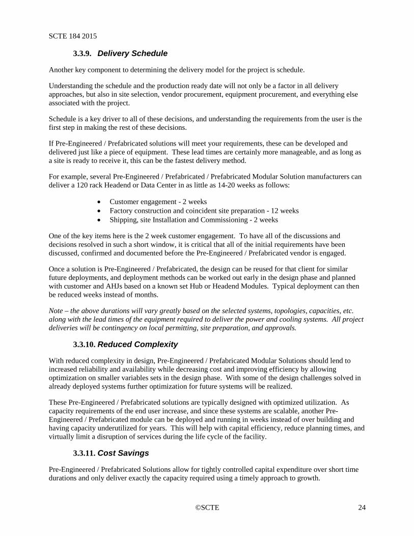
For example, several Pre-Engineered / Prefabricated / Prefabricated Modular Solution manufacturers can deliver a 120 rack Headend or Data Center in as little as 14-20 weeks as follows:
• Customer engagement - 2 weeks • Factory construction and coincident site preparation - 12 weeks • Shipping, site Installation and Commissioning - 2 weeks
One of the key items here is the 2 week customer engagement. To have all of the discussions and decisions resolved in such a short window, it is critical that all of the initial requirements have been discussed, confirmed and documented before the Pre-Engineered / Prefabricated vendor is engaged.
Once a solution is Pre-Engineered / Prefabricated, the design can be reused for that client for similar future deployments, and deployment methods can be worked out early in the design phase and planned with customer and AHJs based on a known set Hub or Headend Modules. Typical deployment can then be reduced weeks instead of months.
Note – the above durations will vary greatly based on the selected systems, topologies, capacities, etc. along with the lead times of the equipment required to deliver the power and cooling systems. All project deliveries will be contingency on local permitting, site preparation, and approvals.
Reduced Complexity 3.3.10.
With reduced complexity in design, Pre-Engineered / Prefabricated Modular Solutions should lend to increased reliability and availability while decreasing cost and improving efficiency by allowing optimization on smaller variables sets in the design phase. With some of the design challenges solved in already deployed systems further optimization for future systems will be realized.
These Pre-Engineered / Prefabricated solutions are typically designed with optimized utilization. As capacity requirements of the end user increase, and since these systems are scalable, another Pre-Engineered / Prefabricated module can be deployed and running in weeks instead of over building and having capacity underutilized for years. This will help with capital efficiency, reduce planning times, and virtually limit a disruption of services during the life cycle of the facility.
Cost Savings 3.3.11.
Pre-Engineered / Prefabricated Solutions allow for tightly controlled capital expenditure over short time durations and only deliver exactly the capacity required using a timely approach to growth.
SCTE 184 2015
©SCTE 25
The available low PUETM levels available and low-cost maintenance produce low annual operating costs, and reduce the overall Total Cost of Ownership or Life Cycle Cost.
With increased speed comes capital efficiency. Being able to quickly deploy additional capacity and put it into production faster allows the data center user to make the best use of the capital spent and to also see returns much quicker.
Operations and Staffing 3.3.12.
A component that can be overlooked during the initial design is the plans for operating and staffing the facility. This decision will drive the monitoring and control system design, space planning (people space or no people space), and most of the other systems that are selected during the design phase.
This discussion will also come into play with regard to tier rating requirements for the facility. For example, compliance with the Uptime Institute’s Tier III Rating requires 7x24 staffing at the facility. While most facilities do not seek certification, this is a key element that needs to be part of the design phase.
With the inclusion of DCIM, maintenance can also be optimized, to decrease time-based maintenance (i.e. monthly, quarterly, etc.) to need-based maintenance, with the appropriate redundancy.
Real world owners of Pre-Engineered / Prefabricated facilities have realized very significant savings in maintenance and operations costs associated with this consistency of design.
Note – the consistency of design can be achieved with traditional delivery methods as well.
Environmental Impact 3.3.13.
Building critical IT facilities off-site offers many sustainable advantages over traditional site based brick and mortar construction. Off-site construction is more resource efficient for producing environmentally friendly IT facilities. In the offsite production facility, raw materials are better controlled and waste is reduced. Many of the parts and systems used in the offsite construction are components used across all, or most, products offered by the manufacturer making them attainable and available. Using an offsite manufacturing facility, combined with the shorter onsite construction / installation phase, significantly reduces heavy vehicle and machinery usage, reducing CO2 emissions and carbon footprint for a given project.
Because operation and maintenance are reduced as outlined previously, the environmental impact associated with these activities is also reduced. Less trips to unmanned sites means less CO2 emissions and reduced carbon footprint.
Environmental impact during decommission is also significantly reduced. Many Pre-Engineered / Prefabricated Modular designs can be disassembled and parts either repurposed or recycled. As with installation, this process is much quicker than with brick and mortar Critical IT designs, reducing carbon footprint due to CO2 emissions from vehicles and machinery.
Energy savings 3.3.14.
Many of the same benefits outlined under the Cost Savings and Environmental Impact sections apply to energy savings.
SCTE 184 2015
©SCTE 26
Delivering any facility with much lower PUETMs (1.1 to 1.5) will have an immediate and drastic impact on the annual cost to operate your data center, especially in locations where the cost of power is higher.
The reduced usage of heavy machinery and large construction vehicles as compared to traditional delivery methods, will also save energy during the construction / installation phase. There will still be site work and foundation requirements to deliver the Pre-Engineered / Prefabricated solution, but there will not be a need for repetitive steel or precast deliveries with large erection cranes, etc. as seen on large scale construction projects.
This comparison will be specific to the size and scale of the facility.
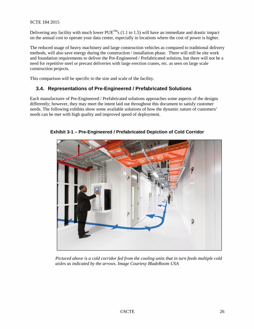
3.4. Representations of Pre-Engineered / Prefabricated Solutions
Each manufacturer of Pre-Engineered / Prefabricated solutions approaches some aspects of the designs differently; however, they may meet the intent laid out throughout this document to satisfy customer needs. The following exhibits show some available solutions of how the dynamic nature of customers’ needs can be met with high quality and improved speed of deployment.
Exhibit 3-1 – Pre-Engineered / Prefabricated Depiction of Cold Corridor
Pictured above is a cold corridor fed from the cooling units that in turn feeds multiple cold aisles as indicated by the arrows. Image Courtesy BladeRoom USA
SCTE 184 2015
©SCTE 27
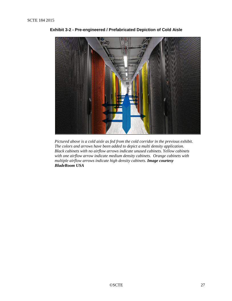
Exhibit 3-2 - Pre-engineered / Prefabricated Depiction of Cold Aisle
Pictured above is a cold aisle as fed from the cold corridor in the previous exhibit. The colors and arrows have been added to depict a multi density application. Black cabinets with no airflow arrows indicate unused cabinets. Yellow cabinets with one airflow arrow indicate medium density cabinets. Orange cabinets with multiple airflow arrows indicate high density cabinets. Image courtesy BladeRoom USA
SCTE 184 2015
©SCTE 28
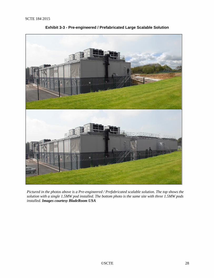
Exhibit 3-3 - Pre-engineered / Prefabricated Large Scalable Solution
Pictured in the photos above is a Pre-engineered / Prefabricated scalable solution. The top shows the solution with a single 1.5MW pod installed. The bottom photo is the same site with three 1.5MW pods installed. Images courtesy BladeRoom USA
SCTE 184 2015
©SCTE 29
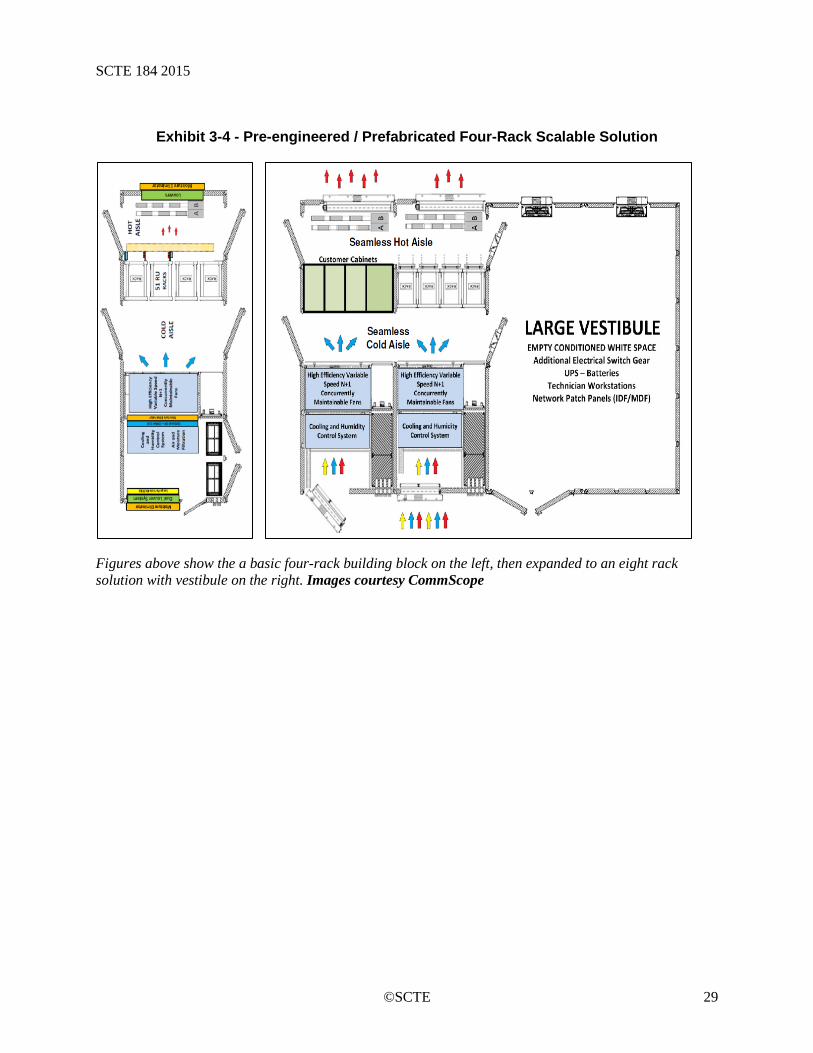
Exhibit 3-4 - Pre-engineered / Prefabricated Four-Rack Scalable Solution
Figures above show the a basic four-rack building block on the left, then expanded to an eight rack solution with vestibule on the right. Images courtesy CommScope

SCTE 184 2015
©SCTE 30
Exhibit 3-5 - Pre-engineered / Prefabricated Ten-Rack Scalable Solution
Figures above show the a basic ten-rack building block on the left, then expanded to an ten-rack solution with vestibule on the right. Images courtesy CommScope
Exhibit 3-6 - Pre-engineered / Prefabricated Twenty-Rack Scalable Solution
SCTE 184 2015
©SCTE 31
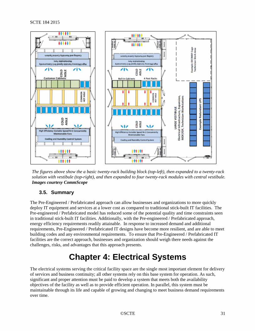
The figures above show the a basic twenty-rack building block (top-left), then expanded to a twenty-rack solution with vestibule (top-right), and then expanded to four twenty-rack modules with central vestibule. Images courtesy CommScope
3.5. Summary
The Pre-Engineered / Prefabricated approach can allow businesses and organizations to more quickly deploy IT equipment and services at a lower cost as compared to traditional stick-built IT facilities. The Pre-engineered / Prefabricated model has reduced some of the potential quality and time constraints seen in traditional stick-built IT facilities. Additionally, with the Pre-engineered / Prefabricated approach, energy efficiency requirements readily attainable. In response to increased demand and additional requirements, Pre-Engineered / Prefabricated IT designs have become more resilient, and are able to meet building codes and any environmental requirements. To ensure that Pre-Engineered / Prefabricated IT facilities are the correct approach, businesses and organization should weigh there needs against the challenges, risks, and advantages that this approach presents.
Chapter 4: Electrical Systems The electrical systems serving the critical facility space are the single most important element for delivery of services and business continuity; all other systems rely on this base system for operation. As such, significant and proper attention must be paid to develop a system that meets both the availability objectives of the facility as well as to provide efficient operation. In parallel, this system must be maintainable through its life and capable of growing and changing to meet business demand requirements over time.
SCTE 184 2015
©SCTE 32
The industry is going through some massive demand changes on the electrical systems as traditional CATV distribution systems and facilities are pressed to deliver the ever changing and higher demand products of the networked age with changes occurring at a much faster pace. The original systems were never conceived to handle the equipment classifications nor provide the power densities now being requested. Electrical systems need to be designed to meet the growing needs of newer equipment and services.
It is economically impractical in many instances to push a completely redundant infrastructure out to the edge across the organization with capacities that meet the future unknowns. Because of this, decisions must be made to look at hardening particular elements to ensure business continuity while balancing against the cost of implementation. Lessons from other industries over the last decade clearly show that overbuilt infrastructure or excessive capital demands can burden an organization to a point that it cannot react to new market opportunities. Overbuilding also has a direct and negative effect on efficient operations.
Efficient operation of the electrical system is directly coupled to the system design, components selection and amount of reserve capacity online. Right-sizing power distribution and conversion to optimize efficiency has been identified by the U.S. EPA, Energy Star program as a key element of energy efficient design. Right-sizing the infrastructure is a critical element of efficient operation. Modularity in layout and design allows for installation of equipment that more closely matches the business needs. Modern systems allow for modular growth without interruption to more closely match need against delivery.
• SOURCE: U.S. Environmental Protection Agency ENERGY STAR Program, Report to Congress on Server and Data Center Energy Efficiency, Public Law 109-431
4.1. Best Practices
As a result of unique challenges moving towards the edge of the network, a stay-alive capability for the critical components of a particular organization is recommended. Creation of this class of equipment can help an organization better size both the "business as usual" operations as well as "stay alive" capabilities. For reference, in this operational practice, this class of equipment will be referred to as Enterprise Critical Equipment (ECE) and is defined as equipment housed within the critical infrastructure space that if not active would have a detrimental effect on operations of the organization. Hardware within this category is typically considered as network transport gear, commercial services, or other penalty driven items that, if services were lost due to a facility outage, would create significant risk or direct financial burden. The classification is purposely left open for determination by the organization to allow for inclusion of additional items or increase in criticality based on local business needs. Issues such as the number of customers served may drive a significant portion of hardware into the ECE category (for example, a primary headend).
Equipment that is classified as ECE will likely need to be served with batteries that have longer duration battery life and be supplied by one or more backup power systems. In addition, this would often allow for growth in deployment as business demand drives funding resources over time.
The diagram below depicts a logical flow for electrical service to a typical hub site. In many instances it can be roughly translated into an electrical single line. Logical adherence to the principles of the distribution system can be obtained with a variety of physical deployments.

SCTE 184 2015
©SCTE 33
Exhibit 4-1: Hub Site Distribution Theory
In general, the infrastructure design should provide:
• Delivery of services with a loss of utility power feed. • Survivalcapability through planned response to mitigate need for redundant backup generation.
This requires emergency response manual intervention. • Minimization of single points of failure. • Ability to maintain systems without interruption of customer services. Increased risk is assumed
with an inherent loss of redundancy during many of the maintenance activities likely driving work to approved maintenance windows.
• Extreme measures fall-back position to maintain EC equipment during a catastrophic event. • Ability to capitalize on existing deployed mechanical and electrical infrastructure.
Taking the ECE concept higher in the network will likely result in more equipment being classified as ECE. The diagram below depicts this concept with the logical flow for electrical service to a typical Headend. In many instances, it can be roughly translated into an electrical single line. There are several possible physical deployments of the logical distribution system.
In general, the ideal Headend is designed to provide:
• Delivery of services with a loss of utility power feed. • Full Pathway Redundancy including UPS and Generator to N+1 levels. • Removal of common single points of failure. • Ability to maintain systems without interruption of customer services. Increased risk is assumed
with an inherent loss of redundancy during many of the maintenance activities likely driving work to approved maintenance windows.
• Dual power pathway to all critical infrastructure systems.
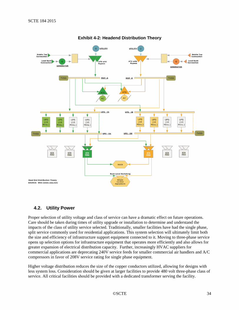
SCTE 184 2015
©SCTE 34
Exhibit 4-2: Headend Distribution Theory
4.2. Utility Power
Proper selection of utility voltage and class of service can have a dramatic effect on future operations. Care should be taken during times of utility upgrade or installation to determine and understand the impacts of the class of utility service selected. Traditionally, smaller facilities have had the single phase, split service commonly used for residential applications. This system selection will ultimately limit both the size and efficiency of infrastructure support equipment connected to it. Moving to three-phase service opens up selection options for infrastructure equipment that operates more efficiently and also allows for greater expansion of electrical distribution capacity. Further, increasingly HVAC suppliers for commercial applications are deprecating 240V service feeds for smaller commercial air handlers and A/C compressors in favor of 208V service rating for single phase equipment.
Higher voltage distribution reduces the size of the copper conductors utilized, allowing for designs with less system loss. Consideration should be given at larger facilities to provide 480 volt three-phase class of service. All critical facilities should be provided with a dedicated transformer serving the facility.

SCTE 184 2015
©SCTE 35
In addition to the technical aspects, good relations with the local electric utility company are necessary. Upgrades and improvement projects can be very expensive. Joint projects or trading work with other community projects can go a long way in saving large sums of money when the time comes to depend on the electric utility company for a project. Not all electric utilities will automatically watch out for the best interest of their customers when they size electrical service. Transformers and electrical service components will not operate at the end user’s desired capacity but are at the control of the supplying utility, either in excess of rating or below rating point. Finding a good, reputable, and knowledgeable electrical engineering contractor is helpful in evaluating service and lobbying the power company to size and replace their equipment to better meet project needs and growth schedule.
The utility feed from utility distribution to the structure should be routed via underground pathway to limit unintended disruption.
4.3. Back-up Power Generation
Traditional backup power sources for critical environments have relied on both diesel and propane generators for a reliable backup power source. These machines work when well maintained and tested. Many operators have experienced failures when incomplete maintenance programs are in place or system tests miss operational modes. Beyond adding modularity and properly sizing the equipment, there is not much that can be done to improve efficiency among the products that are on the market today.
Alternative backup power systems are gaining traction in the marketplace including fuel cells and solar battery supplementation. In the case of solar, this should not be considered as a primary backup source. Understanding system operation, startup times and duration of operation is critical for early adopters of these technologies. For example, hydrogen delivery can be accomplished via high pressure tanks or bulk storage onsite. With a limited distribution network for hydrogen, bulk storage delivery may be on the order of days and not hours.
In the case of solar powered options, understanding the changes in output power over the service lifetime of the solar cells is important. Depending upon the solar technology selected, i.e. mono-crystalline silicon, amorphous semiconductor, or other, the solar cell bank’s output power change over service life due to aging and UV damage and must be properly accounted for during initial design without wasteful, inefficient over-sizing. The maintenance schedule of the storage battery banks selected is equally critical to a solar backup system, and factors such as outgassing (for flooded lead-acid cell arrays), cell charge balancing, and charge controller testing must be built into the maintenance schedule, as for any uninterruptable battery- powered source.
The backup generator source should be sized to include all contingencies for battery recharge, HVAC unit start up and walk-in plans, and UPS transition back to input power source to support all critical infrastructure environmental systems including UPS, cooling, humidification, reheat, control systems, etc. Operationally, there should be no reduced level of environmental support regardless of generator or utility operation. The generator should be supplied with sufficient fuel storage to support a minimum 24 hour run time at full load. A fuel maintenance program should be in place for testing of fuel supply, fuel delivery contract in place and emergency delivery defined with time guarantees.
Generator start batteries should be monitored by automatic systems with alarm, and monitored to provide indication of reliable operation. The generator battery charger should also be monitored to provide indication of reliable operation. Mandating testing of the generators should be accompanied by verification (such as through use of a remedy ticket system and coordination with NOC or TAC) to ensure it is completed. The testing results should be evaluated to understand whether changes to design or operations are required at a particular site or as part of an organizational strategy.
SCTE 184 2015
©SCTE 36
All backup generation systems must be equipped with auto-start and run features to exercise the prime mover, and generator driven by it, no less than once per month, preferable weekly, for a minimum period of time necessary for the prime mover to obtain steady-state operating temperature. The auto-exercise controller utilized should ensure proper operation for genset cranking, starting, generator output frequency and voltage, genset run (i.e. oil pressure, water temp, alternator charge winding output, etc.), cool-down, and prime mover shutdown. The consideration of whether to also include the provision to schedule live switchover and genset load take-up, or load-bank testing of genset switchgear is optional, and should be discussed with the electrical engineering contractor selected for backup system design.
• SOURCE: NFPA70 (the National Electrical Code), NFPA 110 (Standard for Emergency and Standby Power Systems), NFPA 111 (Standard on Stored Electrical Energy, Emergency, and Standby Power Systems)
4.4. Uninterruptible Power Supply (UPS)
According to the U.S. Department of Energy, “Increasing the UPS system efficiency offers direct, 24-hour-a-day energy savings, both within the UPS itself and indirectly through lower heat loads and even reduced building transformer losses.”
Modern transformerless UPS systems are common to the marketplace that offer efficiency ratings in the mid 90% range for lower load values. Low load efficiencies vary by manufacturer and final electrical system topology can affect ultimate utilization rates. Consideration should be given to select products that offer high efficiency during all modes of operation.
M any UPS units are incorporating high efficiency modes of operation with ratings around 99% that blur the line between on-line and off line UPS systems. Utilizing advanced control algorithms, power is transferred between the internal bypass and electronics section based upon input conditions. Proper investigation into a particular manufacturer's control scenario and method is required to understand system operation and potential risk.
A newer approach to UPS system efficiency is to allow the de-activation of modules that are not needed for redundancy or capacity, such that the system will maintain internal module redundancy without sacrifice of a redundant component. This allows a modular UPS system to match equipment against load for real time optimization.
To the maximum extent possible, UPS systems should allow for redundant distribution to critical loads. While extended battery times are available, practical application is usually in the 10-20 minute range with reliance on a backup energy source for extended outages.
Energy storage solutions for UPS systems also include flywheel technology which has a higher initial cost but offers some advantage in footprint and long term maintenance costs. Runtimes on flywheel systems can range in the order of seconds to a few minutes, so additional reliable backup generation is critical.
Minimally, bi-annual maintenance is critical for UPS’s to function properly over time. Battery testing and replacement is critical to ensure the UPS is working when commercial power is lost. A UPS must be installed with external disconnect switches and bypasses to isolate the unit for repair or replacement. Any work to a UPS must be done in the nighttime maintenance window since there’s always a chance of triggering an outage.
UPS system topologies should be developed around equipment that is both modular and scalable to best match load against utilization. In addition, future expansion can be planned that uses overall distribution
SCTE 184 2015
©SCTE 37
topologies that incorporate block modular approaches or non-centralized bypass arrangements with redundancies based upon individual organization's risk tolerance. This would further reduce the chances of failures.
• SOURCE: U.S. Department of Energy, Federal Energy Management Program, Best Practices Guide for Energy Efficient Data Center Design, FEB-2010
4.5. Uninterruptible Power Supply (DC Plant)
D C distribution (Nominal -48 volt) to the rack level should be considered where applications of extended runtime are critical and the business risk of interruption is unacceptable. There are inherent advantages of operating a lower voltage DC distribution system that allow for maintenance and increased modularity and increase runtime. Modern rectifier efficiencies are comparable to UPS system efficiencies and allow for easy N+1 redundancies.
Since DC systems deliver power at a lower distribution voltage, there is a requirement that larger power conductors are necessary to handle the increased current. Conductor increases can be significant across a larger system (range from 4 to 16 times the amount of copper) over the AC systems. However, the installation methodologies typically employed utilizing open cable in tray systems (DC) in lieu of conductors in conduit (AC) can help defer some of the added conductor costs. Voltage drop must be considered as well on DC systems with the lower distribution voltage.
Manufacturers are offering new products to addressing the mix of AC and DC available equipment and developing Inverter options that scale into the DC plant systems and allow for reduced rectifier loading during normal operations.
Organizations should examine the balance between AC and DC distribution based upon a particular facility's equipment load profile, availability requirements, and anticipated outage duration.
D C power distribution's greatest strength is the ease of installation for additional storage capacity. This must be balanced, however, with the thermal loading of a facility and the ability to reject heat during an outage event. Modern equipment densities can overheat an environment in well less than an hour without adequate cooling making any additional installed capacity unusable.
D C plant Redundancy and distribution pathways should be examined to limit potential single points of failure and in some instances redundant DC plant busses and distribution pathways should be established.
4.6. Alternative Power Source Options
Alternative power sources have roles as both primary and secondary power sources. Evaluation of opportunities for utilization of alternative power sources requires ROI evolution that evaluates factors such as facility type, size, existing structure versus new design, growth plans and budget. It many cases, test sites will provide valuable information on which to base plans for more wide-scale roll-outs.
Cable headend facilities rely greatly on the availability and reliability of the local utility company commercial power. This dependency has been very costly. On one hand, as a result of the constant increase in energy rates, and on the other, as a result of the unavoidable grid failures and the resultant need to invest in onsite backup power generation to guarantee uninterruptible power supply to headend critical facilities. To increase efficiency and cut down on power and cooling associated costs, alternative power source systems, such as fuel cells, solar photovoltaic, wind power, or others, can be integrated into the design of facility power system. Such systems can be incorporated into the main hub electrical power
SCTE 184 2015
©SCTE 38
system in various modes or configuration. The three typical configurations of alternative power source systems are independent "stand alone", hybrid and grid-connected systems.
Alternative power sources used in a stand-by mode are more common than continuous-use mode or utility interactive mode.
The following section describes some modes of system integration.
1. Independent-Stand Alone System: A stand-alone or "off grid" system operates independently of the utility main electric grid network. In this mode, the network center is not connected to the main utility grid and relies completely on the power generated from an alternative power source such as solar and/or wind. Often, it requires a method to store excess energy for use when wind or solar conditions are poor. It may incorporate a generator or batteries to support the load during periods of low production. This configuration can also be considered a hybrid system. Other major components of a stand-alone system include: batteries, charge controller, power conditioning equipment, breakers disconnect, meters and instrumentation.
2. Grid-Tied Without Generator or Battery Backup: In this mode, the alternative power source is used in a grid-tied configuration, acting as the main power source. It is designed to displace all or a fraction of the facility’s total electricity needs. As long as the system produces more power than the critical facility demands, the utility grid is not needed and excess power is fed back into the grid. During a lack of local power generation, the grid helps power the load.
3. Grid-Tied With A Generator Or Battery Backup: In this mode, the alternative power source is used in a grid-tied configuration acting as the main power source. It is designed to displace all or a fraction of the facility’s total electricity needs. The alternative power source in battery-based inverters and generator systems can be used to provide back-up power during utility power failures and reduce the cost of energy in a peak load shaving operation. One disadvantage of this setup is the additional cost of batteries and efficiency losses during recharge.
4. Hybrid System Configuration: In a hybrid system configuration, more than one alternative power source can be combined together to sustain the energy need of a facility. It generally consists of a solar PV (photovoltaic) system and wind power generator and/or a diesel generator. Alternative power source systems can be utilized effectively in a cost reduction and energy savings program while at the same time contribute to a greener and more sustainable environment.
Fuel Cell System 4.6.1.
In principal, a fuel cell operates like a battery and uses a chemical reaction process to generate electricity. A single fuel cell consists of an electrolyte that is sandwiched between two electrodes, an anode and a cathode. In general, fuel cells require hydrogen as a fuel source. Hydrogen is stored locally at the site in a pressurized bank of containers, designed to hold pressure of 150 psi. A more sophisticated fuel cell system may contain a fuel reformer or processor that can extract hydrogen from any hydrocarbon fuel such as natural gas, methanol and others. Since there is no combustion process involved, hydrogen fuel cells generate electricity at an excellent emission level compared to combustion engines. It is important to note that a fuel system operating on 100% hydrogen produces no pollutants.
Fuel cells production of electricity depends on fuel cell type, stack size, operating temperature, and the supplied gas pressure. The clean and stable DC power output of a fuel cell makes it ideal to power DC equipment, replace a diesel generator, or become the battery backup system in a DC power plant where space is critical. Depending on the application, a fuel cell system can be designed to power a wide variety of applications, from laptop computers (50-100 Watts) to full site load (1-300 kW). It can also be
SCTE 184 2015
©SCTE 39
deployed in a central power generation setting (1-200 MW or more). Technology is greatly improving on cost, service life of main components fuel processor and fuel cell stack, and safety.
Fuel Cells Characteristics Include:
a. Efficiency: The efficiency of fuel cells depends on the catalyst and electrolyte being used.
Manufacturers often quote net fuel-to-electric efficiencies on the order of 50%-70% and up for fuel cells running on pure hydrogen and oxygen, under perfect conditions. In field application, the numbers could very well be 5%-10% below the quoted value.
b. Maintenance and Operation: A fuel cell system in itself is somewhat maintenance free, for it has no moving parts. Preventive maintenance is limited to some degree to filter replacement (depending on type and site condition), hydrogen fuel capacity level checks, re-fueling, pressure gauges, and pipe joint inspection for leaks. Hydrogen fuel supply and cylinders exchanges depend on the system usage for the site.
Type of Fuel Cells:
There are six common types of fuel cells:
1. Polymer Electrolyte Membrane (PEM) Fuel Cells 2. Direct Methanol Fuel Cells 3. Alkaline Fuel Cells 4. Phosphoric Acid Fuel Cells 5. Molten Carbonate Fuel Cells 6. Solid Oxide Fuel Cells
National codes and standards, in addition to local authorities having jurisdictions, should be adhered to.
• SOURCE: U.S. department of energy-hydrogen fuel cell maintenance • SOURCE: Canada centers for Minerals and Energy technology • SOURCE: U.S Department of Energy – Fuel Cell Technologies program
Solar Power- Photovoltaic (PV) 4.6.2.
Photovoltaic (PV) solar power generation is becoming one of the most adopted alternative power source across datacenters, cable, and telecommunications facilities. It offers many advantages over diesel generators, batteries and even conventional utility power. Solar power adaptation is growing rapidly, due in part to its proven reliability and maintenance free operation in addition to generous federal, state, and local municipality incentives, tax credits, rebates and the recognition of a good corporate social responsibility.
Photovoltaic systems advantages are many which include but are not limited to:
High Reliability even in harsh climate conditions
• Durability most modules are guaranteed to produce power for over 25 years

SCTE 184 2015
©SCTE 40
• Environmental benefits Unlike diesel generators, PV systems burn no fuel, and are clean and silent
• Low operating cost - PV cells use the energy from the sun to produce electricity and the fuel is free.
Since there are no moving parts the required maintenance is low, other than weather related upkeep
• Modularity - A PV system can be constructed to any size based on energy requirements and available roof or ground space
Some disadvantages may include initial high cost of deployment, weather dependencies, site conditions and the need for batteries for energy storage, which can greatly impact the cost and design complexity. Other major disadvantages are technological inefficiencies and the need for large space for either a roof or ground mounted system.
• SOURCE: Canada centers for Minerals and Energy technology
Wind Power Systems 4.6.3.
Similar to PV solar power system, a wind power generator requires no fuel to operate. It converts part of the energy content of moving air into electricity. A basic wind energy system consists of turbine blades, a gear box and generator, a tower and a balance of system (BOS) package (Inverter, batteries, generator, disconnect breakers, etc.).
The wind power system design must optimize the annual energy captured at a given site. Unlike solar PV 21SCTE Energy Management Operational Practices system, wind power system is a bit more complicated and requires more research and study prior to full deployment of the system. It requires a thorough understanding and determination of how much energy is available at the site in consideration. A wind energy system is only feasible as long as the wind is available at a consistently high velocity. An average yearly wind speed of 15 km/h is usually needed for a typical energy system. Another thing to consider is noise and visual issues.
In general, wind turbines need a clean, unobstructed air channel for efficient operation and energy production. Obstructions, such as buildings or trees within close proximity to a wind generator will create turbulence. As a rule of thumb, turbines mounted in a prevailing wind direction should be installed at least 30 ft.(10m) above obstacles that are within 300 ft. (100m); this distance can be less for objects in non-prevailing wind directions.
Resource: http://maps.nrel.gov/SWERA
4.7. Grounding & Bonding
Correctly designed and well installed grounding solutions are critical to ensure reliable operation. Best practice should dictate a corporate grounding standard based upon code required connections as well as nationally recognized means, methods and procedures.
The grounding and bonding of metallic frames and raceways will minimize potential differences between these components whenever the buildings or surroundings are struck by lightning, or whenever an electrical fault produces fault currents. All metallic parts within a ground plane and a ground system should be grounded to prevent voltage potential from creating a shock hazard.
SCTE 184 2015
©SCTE 41
The effects of Electrostatic Discharge (ESD) events are minimized by maintaining a bonded environment of low impedance paths between grounded points throughout the ground plane and grounding systems. Many metallic parts of the ground plane are capable of storing electrostatic charges. Care must be taken during the installation and maintenance of ESD sensitive devices to ensure that static discharge from other devices and personnel (even personnel wearing wrist straps) are properly transferred to well grounded equipment frames and chassis.
The grounding system should minimize electrical interference on operating network equipment by maintaining a low impedance pathway (bonding) between ground points throughout the network system.
• SOURCE: ANSI/TIA-607-B Commercial Building Grounding and Bonding Requirements for Telecommunications Standard
Power Quality 4.7.1.
Surge Protective Device - SPD (TVSS) equipment should be installed at the service entrance equipment and at the distribution boards serving electronic equipment and incorporated into the PDUs. The SPD at the service entrance will serve to eliminate voltage spikes and transients emanating from the utility. The SPD at the distribution panel level will serve to attenuate transients and noise that are generated internally within the building.
4.8. Power Wiring & Cabling
Energy lost within the distribution portion of the electrical system is generally a result of the transport of the power (conductors) or the transformation of voltage (transformer) or frequency (e.g. UPS or DC plant). All components should be selected with proper examination of individual component efficiencies.
For efficiency of distribution, electrical systems should be well organized across the building or room to limit pathways to the shortest runs and limit the distances lower voltage conductors need to run. Power losses in the distribution system become heat that must be removed by the air conditioning systems. Depending upon the component, or locations, specific considerations must be made during the sizing of cooling systems. Any savings achieved within the electrical system will have the direct result of cooling savings within the over system.
When sizing conductors, consideration should be given to both voltage drop characteristics and thermal efficiencies. Voltage drop for a conductor is the product of the conductor's resistance and the current, where the power lost for a given conductor is the product of the conductor's resistance and the square of the current. Cable length is an inherent part of the resistance of the conductor and is therefore accounted for in the calculations. In practical terms, appropriately sized conductor can provide better voltage characteristics and account for less energy loss in the system.
To allow for better metering and monitoring of system performance and improve operational availability and maintainability, dedication of distribution components to systems should be considered.
Cable lengths should be maintained at the minimal necessary length. Avoid coiled lengths and excessive loose cable. All cables should be dressed neatly and should not block equipment airflow.
4.9. Maintenance Considerations
Routine inspection of electrical distribution components, including internal conditions and an IR scan of the electrical distribution pathway should be conducted annually.
SCTE 184 2015
©SCTE 42
A spare parts program for critical electrical components should be provided; a more centralized (Regional) program can be applied to allow for diversity.
Provide a bypass feature on all transfer switches that are single pathway devices. Allow the load to remain energized during maintenance activities, with reduced availability and manual transfer between utility & generator.
An up-to-date short circuit analysis, coordination and arc flash study should be available indicating appropriate equipment ratings and any adjustable devices set to study values.
Chapter 5: Cooling Systems This section includes information and resources related to cooling systems for critical space.
The design and operation of cooling systems for critical space represent an area of significant energy utilization as well as an opportunity for implementation of efficiency measures and savings.
There are also important variables to consider, and appropriate design decisions for one location, or facility type, will not necessarily be the same for another. A small hub site will have very different characteristics and requirements than a large regional or national data center. In addition, the benefits of certain efficiency measures will be greatly affected by local climate conditions.
5.1. Best Practices
The following general best practices are defined based on their value in providing opportunities for energy efficiency while still maintaining base requirements for availability, maintainability and security.
Goal Temperature & Moisture Conditions 5.1.1.
Goal temperature and moisture levels should be defined for the facility and communicated to those personnel responsible for its maintenance. Factors that impact the goal operating ranges for the equipment space should take into consideration both the requirement for hardware availability and goals of operational efficiency.
Maintaining appropriate temperature and moisture level balance at the equipment intakes is a necessary measure for reliable hardware operations. Most hardware manufacturers define both a maximum and an optimal goal range for their equipment electronics. Operating for an extended period at the extreme limits of the operating range, or exposing the equipment to drastic, short-term fluctuations within the range, can damage the hardware and/or impact its reliability. The operating environment specifications provided by manufacturers are the absolute hardware limits and should not be considered guidelines for normal continuous operation.
• SOURCE: ASHRAE - 2011 Thermal Guidelines for Data Processing Environments – Expanded Data Center Classes and Usage Guidance, Whitepaper prepared by ASHRAE Technical Committee (TC 9.9 Mission Critical Facilities, Technology Spaces and Electronic Equipment, 2011
Goal operating conditions may vary slightly between manufacturers. In some cases, this may be a range, while in other cases, it may be a goal point. It will not be possible, in practical application, to maintain uniform conditions at all hardware intakes. The ability to balance conditions will be impacted by factors such as the design of the air conditioning, orientation of the hardware, and size and lay-out of the room. In
SCTE 184 2015
©SCTE 43
some air conditioning designs, the position of the hardware within the rack (top versus bottom) can also have significant influence on intake conditions. Unlike earlier specifications, most new guidelines take into consideration the fact that hardware intake conditions will vary across the face of a cabinet. This is one of the reasons why the newer recommended ranges are typically wider. Other influencing factors are related to wider hardware operating tolerances and attempts to broaden acceptable conditions so as to accommodate efforts at increased energy efficiency.
• SOURCE: US DOE Best Practices Guide for Energy-Efficient Data Center Design (Environmental Conditions), February 2010
Industry standards have attempted to provide standardized recommendations for hardware intake conditions.
For critical space within the telecom industry, the following ambient hardware intake conditions are recommended.
Exhibit 5-1: Recommended Temperature & Humidity Levels
ASHRAE 2011 ALLOWABLE RECOMMENDED
CLASS A1
Dry-Bulb Temperature
15-32°C
59-89.6°F
18-27°C
64.4-80.6°F
Humidity Range, Non-Condensing 20-80%RH 5.5°C (41.9°F) DP to 60% RH
and 15°C (59°F) DP
CLASS A2
Dry-Bulb Temperature
10-35°C 50-95°F
18-27°C
64.4-80.6°F
Humidity Range, Non-Condensing 20-80%RH 5.5°C (41.9°F) DP to 60% RH
and 15°C (59°F) DP
• Class A1: Typically a data center with tightly controlled environmental parameters and mission critical operations
• Class A2: Typically information technology space or office or lab environment with some control of environmental parameters
The recommended ranges should be used as the guideline for critical facility conditions. Any decision to operate outside these recommendations in order to achieve greater operational efficiencies should address the considerations outlined in this document and the associated reference standards and guidelines. In the document, ASHRAE 2011, Thermal Guidelines for Data Processing Environments, ASHRAE defines the “recommended” envelope as "the limits under which IT equipment would operate most reliably while still achieving reasonably energy-efficient data center operations." ASHRAE 2011 provides data and guidance for applying the included recommendations and practices in a manner that allows for customization to the specific geography, design, mission and requirements of a given facility. It provides maximum allowable limits, along with data on reliability impacts, failure causes and other factors that can impact reliability if conditions are maintained outside recommended levels. This guideline is clear in stating that the
SCTE 184 2015
©SCTE 44
recommended envelop should not be considered “absolute limits of inlet air temperature and humidity for IT equipment”, but goes on to state that, “Any choice outside of the recommended region will be a balance between the additional energy savings of the cooling system versus the deleterious effects that may be created in reliability, acoustics, or performance.”
• SOURCE: ASHRAE - 2011 Thermal Guidelines for Data Processing Environments – Expanded Data Center Classes and Usage Guidance, Whitepaper prepared by ASHRAE Technical Committee (TC 9.9 Mission Critical Facilities, Technology Spaces and Electronic Equipment, 2011
It is essential to note that the changes to these recommendations were not a simple expansion of the recommended ranges. These changes also acknowledge the differences in hardware intake conditions that are typical in different locations within a critical space, as well as differences in intake conditions that are dependent on the position of the hardware. Previous guidelines were generally based on the assumption that conditions would be uniform and that a single-point measurement per location would be representative. If the newer, wider recommendations are used, they must be applied to all hardware intakes, regardless of location. Using these guidelines to define a wide set-point for an air conditioner, for example, can lead to variable and potentially harmful or undesirable conditions at the hardware. This range should be applied to control conditions in the hardware air intake areas, and should be comprehensively verified. An evaluation program, independent of monitoring and controls, is recommended.
If outside influences are controlled, it should be possible to maintain recommended conditions in the equipment space in an efficient manner. These goal conditions should be incorporated into any plans or programs designed to increase the efficiency of the environmental controls for the critical space.
5.2. Cooling Capacity & Heat Load Calculations
Air conditioning systems for critical spaces will vary based on the specific requirements of the space.
Geographic location, building type, installed equipment and other factors will all influence the type of system used at a given facility. In all cases, the systems couple the localized environment with the heat rejection to transfer the heat energy from the point of injection into the space to the outside of the building. They commonly contain the controls and equipment that establish the conditions at the local level.
When determining air conditioner capacity, it is important to evaluate the system specifications based on the goal conditions for the critical space. Manufacturer published capacity data for air conditioners is often based on higher temperatures than those recommended for critical IT spaces. If the specifications are not adjusted for goal conditions, the result may be an undersized system.
Systems designed specifically for critical IT spaces will typically have a higher sensible heat ratio than those designed for other types of spaces. The Total cooling capacity of the unit is a combination of the latent and sensible cooling capacities, where sensible cooling is the removal of heat and latent cooling is the removal of moisture. In an IT equipment space, a system with a high sensible heat ratio will be more effective at removing the heat generated by the equipment without also removing moisture from the space. Moisture control of the space is important, and it may, at times, be necessary to remove moisture from the critical space. Removing it in an uncontrolled manner through the air conditioning system, however, can result in the necessity to mechanically reintroduce this moisture. This is an unnecessary use of energy, detracting from the overall efficiency of the facility. Ensuring that the system has appropriate sensible cooling at the desired operating conditions will lead to more efficient cooling of the IT space.
SCTE 184 2015
©SCTE 45
In all cases, the cooling systems for the critical spaces should be designed specifically for IT loads (with an appropriate sensible heat ratio) and should be dedicated to the critical space.
Redundancy of cooling systems should be incorporated into the design. The manner in which this is calculated will be dependent on the characteristics of the air conditioning systems, heat load and the facility. Redundancy should be evaluated across all aspects of the facility so as to avoid unnecessary costs. It should look at the redundancy of the individual mechanical systems, the facilities, as well as redundant features of the hardware itself. This evaluation will determine the appropriate distribution of investment in equipment and identify areas where efficiency of operations can be implemented.
The air conditioning system should be designed with a minimum N+1 redundancy. Redundancy calculation should not be based solely on capacity versus load. It should take into consideration physical design, equipment locations and air distribution. The loss of one unit should not impact the ability of the system to maintain goal conditions within the space.
Energy savings obtained from reducing the number of active air conditioners is primarily related to eliminating the cost of operating the fan motors along with a certain amount related to removal of heat produced by the motors themselves.
When considering turning off air conditioners for energy savings, unintended results or negative influences must be considered. Localized influences or backflow through systems that are turned off are examples of issues that should be considered. Any program should include comprehensive planning and validation, adjusted to the specific site.
Chapter 10 has additional information regarding equipment planning within the rack space, and consideration for equipment types in rack distribution throughout the room.
5.3. Mechanical Equipment Designeration for equipment types in rack distribution throughout the room.
The mechanical cooling systems should be designed such that they can be deployed in a modular fashion in order to best match utilization against system capacity. Within each major growth stage, the modular systems should allow for capacity growth without load interruption. The design should be highly scalable, and designed in a redundant configuration.
Infrastructure should be designed so new A/C systems can be purchased and installed quickly to meet future requirements. If the system design calls for future AC unit installation to support load growth, all piping (taps, isolation valves, etc.) and electrical conduit work should be completed at the time of initial construction for areas within the protected computer room environment.
Cooling units for critical spaces are available in several design configurations. Common designs include chilled water, direct expansion air cooled, direct expansion water cooled, direct expansion glycol cooled, and hybrid designs based on energy efficient applications of both existing and new technologies. Appropriate design for the cooling system design for a critical space is impacted by many factors, including the size and heat load of the equipment space and the geographical location of the facility.
Chilled Water Systems 5.3.1.
Chilled water based air conditioning systems do not utilize refrigerant in the portion of the unit used to cool the critical space. The units used a chilled water or a water / glycol mixture to remove heat from the air. This chilled water mixture runs through the cooling coil over which room air passes. Heat is
SCTE 184 2015
©SCTE 46
transferred to the chilled water mixture and carried out of the room via a return chilled water loop. The removed heat is then transferred to the outside any number of varying technologies including, cooling towers, water cooled chillers, air cooled chillers, heat exchangers, free cooling heat exchangers or combinations of these technologies.
Refrigerant Based Systems 5.3.2.
Refrigerant based systems utilize refrigerant and compressors to remove heat from the controlled space. The heat is then transferred to another medium such as air, water or a water-glycol mixture. The exchange, from refrigerant to secondary medium can occur within the controlled space or outside the controlled space, depending on the design employed.
Direct Expansion (DX) Systems 5.3.3.
The direct expansion (DX) systems incorporate dedicated compressors and refrigeration circuits and a distributed modularity of the refrigeration system. They can be small packaged units or larger external units. Chilled water units rely on central chilled water plant. Regardless of the design of the cooling system, options (free-cooling, variable speed fans, advanced controls, etc.) are available to maximize energy efficiency. These design features should be used wherever possible, based on their appropriateness to the specific application.
Direct Expansion, Air Cooled Systems 5.3.3.1.
The direct expansion (DX) air cooled systems incorporate dedicated compressors and refrigeration circuits and a distributed modularity of the refrigeration system. The cold refrigerant passes through coils over which air from the controlled space passes. The heat from the IT space is transferred to the refrigerant and carried out of the IT space by the refrigerant circuit. Outside condensers then reject the heat to the atmosphere. Air cooled units can be small packaged systems or larger external systems. The primary advantage of these systems is the distributed modularity and inherent redundancy. The main disadvantage is the lack of significant free cooling availability.
Glycol Cooled Systems 5.3.3.2.
Glycol-cooled air conditioning systems are also a DX design. These systems, however, use a glycol/water mixture that flows through the heat exchanger to remove the heat from the refrigerant within the critical space. Similar to the air-cooled systems, room air flows over a coil transferring the heat to the cooled refrigerant within the coil. The refrigerant in not, however, pumped out of the critical space but transfers the removed heat to a glycol water mixture via a heat exchanger, most often located within the unit. This mixture is transported outdoors, where the heat is expelled to the atmosphere by dry coolers equipped with strong fans. The glycol keeps the solution from freezing during winter operation. An advantage of this system is that the absorbed heat can be pumped much further than the refrigerant in an air-cooled system. The initial cost to implement this system is greater, but there may be significant ongoing energy savings, depending on external climatic conditions and free cooling options selected. A potential concern is the introduction of liquid into the critical space.
Water Cooled Systems 5.3.3.3.
Water cooled air conditioning systems are also DX. The in-room portion of the system is very similar, and operates near identically to, glycol based systems. The difference is that instead of a glycol/water mixture, the heat exchangers transfer heat to condenser water. The condenser water flows in a continuous loop and is typically transported outside to a cooling tower where the heat is rejected. The advantage of this approach is that water can absorb more heat than either refrigerant or glycol. Systems that take
SCTE 184 2015
©SCTE 47
advantage of evaporative cooling can potentially reduce energy costs. As with the glycol systems, a potential concern is that water may be introduced inside the critical space in some applications. Another disadvantage for some applications, is that this is an open loop system where the condenser water evaporates, potentially resulting in intensive water usage. These system can also be set up with municipal water as the primary or secondary source, where permitted. The municipal water can then be used in failure scenario, or as the primary source of cooling. Any potential for increased utility charges and any environmental impact should be evaluated when considering this type of system.
Hybrid Cooling Systems 5.3.4.
Hybrid designs of both custom and productized cooling solutions are beginning to enter the marketplace, which take advantage of the local environmental conditions to reduce energy costs or environmental impact to a facility. These hybrid designs often include one of the traditional designs described previously but also may include aspects of direct or indirect heat exchange between the controlled space and the exterior environment. Direct exchange methods include moving outdoor air into the controlled environment. Designs of this nature should evaluate the protective controls and operating envelope defined for the critical space and make sure that risk to interruption is evaluated against potential energy savings. Indirect exchange includes non-powered or minimally powered systems that maintain isolation between the critical space and the exterior environment. These systems can use aspects of evaporative cooling to supplement local temperature conditions to expand operating envelopes.
• SOURCE: ASHRAE Design Considerations for Datacom Equipment Centers, 2005, p23-24 • SOURCE: US DOE Best Practices Guide for Energy-Efficient Data Center Design (Cooling
Systems), February 2010’
Conditioned Air Distribution 5.3.5.
Balancing cooling system airflow capacity with the distribution of conditioned air in the critical space is essential to both hardware availability and efficiency of energy usage. This includes everything from the air conditioner selection to the final distribution at the hardware. Cooling short cycles, air distribution tile placement (in a subfloor system), hardware alignment, influences on control sensors and similar issues should be evaluated. What may seem like an isolated or inconsequential issue may have a far-reaching or cumulative impact on efficiency and energy consumption.
Installing and maintaining adequate cooling capacity in the critical space is only a portion of the effort to remove the heat generated by the IT hardware. The conditioned air must be distributed to the areas in need of heat removal, and the heat must be efficiently returned to the air conditioners for reconditioning.
Determination of the air distribution system utilized is based on a number of criteria, such as size, location, use, heat load, cooling design, etc. A ROI analysis should be performed during the design phase to assess the financial commitment of utilizing a particular air distribution methodology.
While many variations exist, most conditioned air distribution methods for the critical space can be categorized as ambient or underfloor. Ambient systems can be based on in-room or through-wall packaged units, or overhead distribution from packaged or centralized systems. Underfloor distribution is typically accomplished through packaged units distributed within the critical space. Variations or supplements to these systems can include in-row or cabinet-top close coupled cooling for high density areas.
Both the ambient and underfloor systems have advantages. Raised floors can offer more flexibility to accommodate changes in hardware load in the critical space, and can easily accommodate redundancy.
SCTE 184 2015
©SCTE 48
These are typically most appropriate in larger facilities (such as data centers), but are often difficult to justify in smaller facilities with a generally stable heat load and predictable growth (such as hub sites).
Subfloor Air Distribution 5.3.5.1.
Appropriate air distribution can be accomplished in a variety of ways including subfloor air plenum delivery, overhead air delivery, end of row delivery; each brings with its own challenges. While subfloor air distribution is often the most flexible and accommodating, many other strategies can be effectively employed if their associated challenges are addressed and managed properly.
The subfloor void in a down flow air conditioning system is designed to act as a plenum; with air distribution tiles (perforated tiles, grilles, etc.), cable cutouts and other openings in the access floor acting to distribute the conditioned air. Adequate subfloor pressure levels are necessary to deliver the conditioned air. If subfloor pressure is inadequate, the conditioned air will not be delivered to all areas in need of heat removal.
Data compiled from ASHRAE publications and floor tile, hardware and environmental support equipment manufacturers shows an appropriate subfloor pressure of between 0.030" and 0.050" water column (WC), with a minimum recommendation of 0.02" WC. Air distribution placement should be determined in a manner that ensures appropriate intake conditions to all hardware, regardless of where it is located in the racks. The fixed number and size of openings in the access floor, those designed for air distribution and those necessary for cable passage or similar, must be balanced with the fixed fan capacity of the air conditioners. If there are too many opening, pressure will be too low and conditioned air may not be delivered to the critical hardware. If the opening are too few, conditioned air may not be distributed evenly to areas in need. Additionally, pressure levels may be too high, increasing air delivery velocity, which may allow air to bypass critical hardware air intakes. The type of design requires active management of air distribution tile placement but not number.
If variable speed fans or unit cycling are employed, test scenarios should be defined to ensure that these options do not result in inappropriate hardware conditions.
• SOURCE: ASHRAE Design Considerations for Datacom Equipment Centers, 2005
Variable speed fans can be employed to control air volume and save energy. The subfloor pressure / air distribution tile number relationship described in the preceding paragraphs may change depending on how the variable speed drives are controlled. If the drives are controlled through differential pressure sensors across the subfloor supply air plenum, the controlling sensors should be set to maintain the appropriate subfloor pressure levels described above. In this scenario, energy is saved by only placing enough air distribution tiles in place to cool the installed heat load. If the heat load is below the design capacity there will be fewer opening that can be accommodated, increasing pressure in the plenum. This increased pressure causes the variable speed drives to reduce the amount of cfm and subsequent energy use. This type of control requires active management of air distribution tile number and location.
If the drives are controlled via a network of hardware intake temperature sensors, elevated temperature conditions at the hardware, trigger the variable speed drives to increase the amount of air delivered. Typically, in this type of system, the number of air distribution tiles is fixed and similar to that described above for non-variable fans. Active management of air distribution tile placement is often still necessary if the increased air volume does bring temperature levels within design parameters due to heat load density or other conditions.
SCTE 184 2015
©SCTE 49
While dedicated intake and exhaust aisle that focus on the airflow design of the hardware are central to most approaches, implementation can vary dramatically.
1. Balanced Approach: A balanced approach to air distribution will often provide an effective cooling of the critical space, while providing appropriate conditions to the hardware. This approach incorporates moderate and controlled temperature conditions at the intakes of the server. The levels attained will closely approximate the recommended operating ranges of the installed hardware as well as the ASHRAE recommended levels. This results in CRAC operation at or near the operating range where units are 100% sensible; thus, avoiding undesigned and unnecessary dehumidification, and subsequent re-humidification. This is often employed in legacy, conventionally designed or traditional data centers where the necessary full implementation of Hot Aisle & Cold Aisle, or other containment tragedy, is not possible or cost justified. When the balanced approach is properly implemented, energy savings can be gained through shutting down excess redundant air conditioning capacity for use as back-up or when needed for added heat load. For more information, see section 5.8 Airflow Management in Critical IT Space for more detail descriptions.
2. Hot Aisle & Cold Aisle (Containment): Many sites base air distribution on some variation of hot and cold aisle separation. If hot-aisle / cold-aisle configurations are used, effective physical isolation for the hot and cold aisles must be put in place to realize real effect on efficiency and savings. This will typically require design features such as full hot-aisle or cold-aisle containment, blanking panels or curtains, variable speed fans, control sensor modifications (such as supply-side control, adapted set-points, pressure differential controls, etc.) coupled airflow volumes and enhanced monitoring and verification. The ROI for these necessary actions must be evaluated against the predicted benefits for a given installation. Partial implementation will not provide proportional results; it may result in no benefits or actual negative influences. For more information, see section 5.8 Airflow Management in Critical IT Space for more detail descriptions
It is often more practical and more easily justifiable to achieve the desired outcome from this design approach in a carefully planned new facility than in trying to fix a flawed implementation at a later date. One of the most common mistakes is that of a partial hot-aisle / cold-aisle implementation (good intentions, but not carried through), with subsequent poor results. Subsequent equipment evolution leads to hot spots that are then mitigated by reducing the overall room temperature, leading to significant inefficiencies (to the point of installing additional HVAC capacity and introducing short circuiting issues). Successful implementation of this approach relies on careful planning of equipment placement, growth plans, air conditioner design, and other factors, any one of which can undermine the effectiveness of the plan if not properly implemented. For more information on containment air distribution see Chapter 7: Contaminant Management.
Operators should consult and receive approvals from the town or county Authority Having Jurisdiction (AHJ) as well as their Insurance Provider before installing cold or hot aisle containment systems. Both entities may express concerns about safety and or fire suppression.
SCTE 184 2015
©SCTE 50
• SOURCE: US DOE Best Practices Guide for Energy-Efficient Data Center Design (Air Management), February 2010
5.4. Ambient Air Distribution
For smaller hub sites, the size of the facility and heat load will often make subfloor air distribution impractical and not cost-effective. Ambient air distribution can be achieved through a variety of systems, such as overhead distribution through ducts and diffusers, up flow packaged units or through-wall packaged units.
If packaged units with supplies and returns in close proximity are used, it is important to ensure that cooling system placement and hardware orientation are coordinated to minimize obstructions to airflow and to limit cooling short circuiting. Single-point cooling typically works sufficiently for small facilities with a generally static heat load. While factors such as co-location of utility sources, convenience for maintenance, security, installation costs, etc. are often the driving factors for the choice of air conditioner type and placement, it is critical that the type of load being cooled place a central decision in sourcing equipment. Many wall-mounted, split systems will be subject to an inherent degree of cooling short circuiting. This can be mitigated somewhat by designing some separation between units, and adjusting the position, type or setting of diffusers the regulating control sensors.
• SOURCE: ASHRAE Design Considerations for Datacom Equipment Centers, 2005
Rack Level Cooling & Air Distribution 5.4.1.
It is essential that the specific designs of the particular hardware units in place in a room be taken into account when determining appropriate conditioning and air distribution. Different types of hardware often utilize vastly different internal airflow designs. These designs must be taken into account when planning and maintaining the room.
Avoid placing hardware so that the exhaust of one unit enters the intake of the next. While this may appear obvious, it is a very common problem. In addition, be sure that air can pass through the hardware unrestricted. Do not place hardware so that other hardware, walls, or furniture block hardware intake or exhaust. . Do not place signs or placards on the perforated face of cabinet intakes. Do not store items on top of units of hardware that exhaust from the top. This blocks airflow and can contribute to hardware failures or degraded performance.
Blanking panels should always be used to fill empty horizontal and vertical spaces in the rack to maintain proper airflow.
Using a rack without blanking panels could result in inadequate cooling that could lead to thermal damage. Overheating due to exhaust air recirculation and the benefits of using airflow management blanking panels are well recognized by IT equipment manufacturers.
Selection of third-party racks is an integral factor in the cooling of the hardware. When third- party racks are used, the perforated door styles are recommended. These design styles take advantage of the inherent lateral fan driven airflow patterns of the installed hardware. If open post style racking is utilized, blanking and exhaust recirculation techniques should not be overlooked.
In instances where a high density cabinet is required, the use of close coupled cooling cabinets may be required. In this approach, cabinets are coupled with an in-row (or individual) air conditioning system, eliminating its dependence on the ambient space of the room. No air leaves the cabinet and enters the space, except when the doors are open. Efficiency in these cabinets is realized due to the close proximity
SCTE 184 2015
©SCTE 51
of the hardware to the cooling system; this closeness is what allows these cabinets to be equipped with high density heat loads.
5.5. Control Systems Design & Maintenance
Sensor accuracy and correct control settings are a critical aspect of efficient utilization of cooling systems. This is an area that is often overlooked in both the design/specification phase and ongoing operations. In the most basic sense, it will be difficult or impossible to control conditions as intended if the regulating sensors are registering incorrectly or have inadequate accuracy. This can lead to excessive, unnecessary conditioning, humidification or reheat. It can also lead to individual units fighting each other with conflicting functions. All these conditions result in unnecessary energy utilization and costs. Verification of sensor accuracy and control set points should be incorporated into the regular maintenance of the mechanical systems for the critical space. This verification should be included in the preventative maintenance schedule for the equipment as well as part of any audit of the infrastructure or environment.
Advanced monitoring and trending functionality are recommended. These will provide the tools necessary to evaluate conditions and regulate system functions to maximize efficiency efforts such as economizer functions.
5.6. Moisture Control
Control of moisture levels is a necessary, but often an expensive aspect of maintaining appropriate conditions for a critical space. As with temperature, hardware manufacturers typically define both broad operating ranges for extreme short-term exposure and more narrow recommended ranges for normal operating goals. Industry groups have attempted to summarize these recommendations and, where possible, to broaden them to provide opportunity for energy savings.
Controlling humidity via dew point (DP) rather than relative humidity (RH) has been recommended by ASHRAE TC 9.9 since 2008. But the vast majority of critical spaces still control on RH. This includes new facilities being designed and constructed today. The reasons that RH control continues to be incorporated include, familiarity, existing equipment design and existing control schemes. However, relative humidity has far less applicability in high density critical spaces than it has in lower density, legacy facilities. When the temperature level recommendations outlined in ASHRA TC9.9 2008 are adopted and utilized in a high density facility, RH levels will vary dramatically across the space. Thus it becomes near impossible to specify or recommend associated RH recommendations. Dew point, however, will essentially remain consistent across a room at a given moment. Room temperature levels must remain above dew point to avoid condensation and undersigned dehumidification, further adding to the benefits of dew point control.
It should be noted that excessively high relative humidity levels can expose hardware to potentially damaging corrosive conditions and other physical damage. For this reason, ASHRAE TC 9.9 has recommended a maximum RH level in combination with the dew point range recommendation. . Extreme fluctuations in RH levels have been shown to impact hardware and operations. Adhering to the ASHRAE recommendations for moisture control, both DP and RH will limit this impact.
Mechanical moisture control can be expensive. Physical measures such as maintenance of perimeter integrity can help minimize these costs. Similarly, it is important to verify the accuracy of sensors and controls and to avoid battling between units. The design of the humidification system can also impact energy usage. If it is determined that mechanical control of moisture levels is not possible, or necessary, due to site location or other factors, comprehensive monitoring and physical personnel grounding controls and practices should be put in place to mitigate threats to hardware operations.
SCTE 184 2015
©SCTE 52
• SOURCE: 2008 ASHRAE Environmental Guidelines for Datacom Equipment—Expanding the Recommended Environmental Envelope
• SOURCE: MEPTEC Report. The Threat to Miniaturization of the Electronics Industry. Quarter 4, 2004
• SOURCE: US DOE Best Practices Guide for Energy-Efficient Data Center Design (Cooling Systems), February 2010
• SOURCE: ANSI/BICSI 002-2011, Data Center Design and Implementation Best Practices
5.7. Perimeter Integrity & External Influences
A superior vapor barrier is essential in maintaining controllability over in-room conditions. Any significant breaches in the vapor barrier of the room will expose the computer room to potential negative influences. This affects the ability of the primary air conditioning system to achieve and maintain appropriate conditions, and results in excessive, unnecessary energy usage as the system struggles to condition and humidify air from outside the room in addition to the room loads. Penetrations in the perimeter of the subfloor void supply air plenum can also dramatically reduce subfloor pressure, waste cooling capacity, and contribute to negative room pressurization.
Cooling systems that include outside air introduction in a designed manner should be evaluated closely. While this is an integral feature of some economizer functions, the exposure and impact must be understood and controlled within acceptable limits. External air introduction must be appropriately filtered to limit the introduction of damaging external contaminants. The ability to benefit from economizer features will vary dramatically geographically. Data is available to evaluate free-cooling potential of a given location. This is typically based on temperature levels. Ideally, calculations and controls should avoid allowing extreme RH levels that could impact hardware operations.
• SOURCE: BICSI Data Center 002-2010 – Data Center Design and Implementation Best Practices (Thermal Management). June, 2010.
5.8. Airflow Management in Critical IT Space
One of the most important aspects of the mechanical design of today’s critical IT space has been the implementation of air stream separation. Minimizing the mixing of the cool supply air and the hot exhaust air is the fundamental concept behind air stream separation. There are essentially three types of air stream separation, hot aisle containment (HAC), cold aisle containment (CAC) and isolation.
All of these, as well, as traditional approaches, rely on front-to-front / back-to-back cabinet / row arrangement. Blanking panels and zero U space blanks are also imperative in all designs to minimize exhaust recirculation.
The recommended environmental envelope for IT equipment was expanded when ASHRAE issued the 2008 version of “Thermal Guidelines for Data Processing Environments”. The recommended range for inlet conditions was expanded from 68°-77°F to 64.4°-80.6°F. This increase to 80.6°F allows for even more efficiency gains from the use of air stream separation than possible prior to the change. This was further clarified in the 2011 issuance of “Thermal Guidelines for Data Processing Environments”.
Traditionally, prior to the implementation of air stream separation, the flooded room approach was typically utilized in critical IT spaces. While designs vary widely, the flooded room most commonly employed perimeter air conditioning units (CRAHs or CRACs) and a raised floor supply plenum. Other variations of the flooded room include overhead ducted supply from either perimeter or remote air conditioners, and open supply / open return from perimeter air conditioning units. As the industry
SCTE 184 2015
©SCTE 53
continues to design to the air stream separation models, these legacy designs will become less prevalent. However, numerous IT spaces with these traditional approaches are still in use today and the use of airflow management to improve efficiency of these designs should also be explored.
Airstream separation approaches include hot aisle containment, cold aisle containment and isolation. Cold Aisle Containment (CAC) is typically deployed in a traditional raised floor / perimeter based cooling designs. This fact allows this design to be most readily adapted to legacy facilities. CAC uses end caps or doors and covers or roofs to contain the cold allowing the rest of the critical space act as the return plenum for the perimeter based cooling. Alternatively, solid front cabinet doors on sealed cabinets can be employed. Hot aisle Containment (HAC) encloses the hot aisle leaving the cold aisles open to the remainder of the critical space. While this approach can be adapted to legacy facilities, it is more challenging to implement than CAC in legacy facilities due to the need for a hot air return plenum stretching back to the air conditioning, whether perimeter based or outside the critical space. Total isolation is relatively new approach and involves purpose built facility that completely separates the hot and cold aisles, essentially containing both. The aisles on each end of the hardware rows act as supply plenums and exhaust or return plenums, respectively, moving the air through the system in an efficient pattern. The isolation approach relies on extensive monitoring and control to ensure the most energy savings possible. Each of these three approaches offers both benefits and challenges, while increasing energy efficiency of the critical environment.
5.9. Approach Evaluations
Flooded Room 5.9.1.
Flooded room approached represent traditional or legacy designed critical IT spaces which do not typically utilize containment (Hot Aisle Containment, Cold Aisle Containment and Isolation). However, these legacy facilities can often have a containment approach retrofitted to accommodate improved efficiency.
Raised Floor and Down flow Air Conditioning 5.9.2.
This approach represents the traditional legacy data center with perimeter (either in-room or gallery) located down flow air conditioning units, a pressurized subfloor void supply air plenum, and distributed air distribution grilles or perforated tiles.
The general airflow patterns associated with this design involves room air entering the top of the air conditioner (Return Air) where it is cleaned by air filter banks. As the Return Air passes over the cooling coil, the air temperature is lowered significantly. Large fans at the bottom of the unit push the conditioned air (Supply Air) into the subfloor void supply air plenum where it is introduced into the critical space access floor grilles or perforated floor tiles. Once in the ambient room space, the air mixes with the hardware heat load and flows back to the air conditioners for re-conditioning.

SCTE 184 2015
©SCTE 54
Exhibit 5-1 – Raised Floor Supply / Open Return Down flow
Image Courtesy Emerson Network Power
Benefits and Challenges of Overhead Ducted Supply
Some of the benefits of the Overhead Ducted design include:
• Reasonably fast response to temperature changes in the room. • Distributed / redundant cooling infrastructure.
Some of challenges associated Overhead Ducted design include:
• Flooded room requires excess fan energy. • Widely varying cabinet heat loads can result in hot spots. • Potential for wide swings in intake conditions due to air conditioner cycling. • Potential for wide variance from lowest to uppermost RUs within a cabinet. • Generally inflexible, does not readily allow changes in air distribution to address
changes in IT heat load. • Cool, high velocity air entering the aisles from above can be a nuisance to
operators. • Ductwork competes for overhead space with items such as electrical buss duct,
copper ladder rack or tray, fiber tray, etc.
There are very few energy saving opportunities with this design. Airflow should be optimized to ensure all directed down into cold aisles. In this design, unlike the traditional subfloor distributed design discussed above, directing all cool supply air into the cold aisle is best practice. The high velocity, directed airflow creates an air curtain, which prevents the hot exhaust from being drawn over the top of the row from the hot aisle. The use of dampers on the diffusers in the ductwork will allow airflow to be directed to the areas of heat load and closed off from those areas where heat load is less Once this airflow is optimized in this manner, consideration to reducing redundancy to the minimum necessary can be considered, thereby reducing fan energy usage.

SCTE 184 2015
©SCTE 55
Fitting fans with variable speed drives (VSD), is an option for energy savings in this design. However, consideration to ensuring the necessary velocity and volumetric rate are maintained to ensure proper cooling. The VSDs should be controlled via a network of rack inlet temperature sensors. When the inlet temperature rises, the VSDs would be commanded to increase fan speed thereby increasing the amount of supply air delivered to the hardware.
Open Supply / Open Return
This design uses perimeter located, down flow or up flow process cooling units. While it is typical to see this design used in facilities without raised floor, it can be implemented on raised floor but the subfloor void would be used as a plenum. As the name suggest, the perimeter located cooling units have both open returns and open supply.
The general airflow patterns associated with this design involves room air entering the top (or the front face of the bottom in the case of up flow units) of the air conditioner (Return Air) where it is cleaned by air filter banks. As the Return Air passes through the cooling coil, the air temperature is lowered significantly. Large fans within the unit push the conditioned air (Supply Air) out the bottom of the unit which is raised above the floor on a stand. Turning vanes direct the air down the cold aisles. Or in the case of up flow, plenum boxes fitted to the top of the unit direct the air down the cold aisles. Once in the ambient room space, the air mixes with the hardware heat load and flows back to the air conditioners for re-conditioning.
In this design, the units need not be located in the critical space. For example, in many hubsites with exterior wall mounted air conditioners fit into this design category.
From a control standpoint, the sensors or stats are often located in the IT space or in the return path to the air conditioner. When located in the IT space, they can be located at hardware intakes, on the same walls as the air conditioners, or the opposite walls of the air conditioners. When designing this type of cooling approach careful consideration should be giving to the location of the sensor to ensure design goals are met. Once the room is operational, it may be found that changes in the location may be required.
Figure 0-

SCTE 184 2015
©SCTE 56
Exhibit 5-3: Open Supply / Open Return
Image Courtesy Emerson Network Power
Benefits and Challenges of Open Return / Open Supply Approach
Some of the benefits of the Open Return Open Supply design include:
Reasonably fast response to temperature changes in the room. Distributed / redundant cooling infrastructure.
Some of challenges associated with the Open Return Open Supply design include:
• Flooded room requires excess fan energy. • Widely varying cabinet heat loads can result in hot spots. • Potential for wide swings in intake conditions due to air conditioner cycling. • Potential for wide variance from lowest to uppermost RUs within a cabinet. • Inherent cool air short circuiting due to proximity of supply and return. • Inflexible, does not allow changes in air distribution to address changes in IT heat load. • Cool, high velocity air entering the aisles from the ends can be a nuisance to operators. • Positioning supplies at cold aisles is not always possible or practical. • Returns are not located at the end of cold aisles.
The energy savings opportunities with this design are even fewer than those of the ducted system. However, the VSDs discussed in that section are also a possibility here.
Containment Approaches 5.9.3.
The deployment of air-stream separation has been one of the most important features of the modern data center mechanical designs. Air-stream separation involves minimizing the mixing of IT equipment "hot" air discharge with its "cool" air intake. The containment approaches discussed here utilize physical separation between the hot exhaust airstream and cooler supply airstream.
The ASHRAE's 2008 "Thermal Guidelines for Data Processing Environments" expanded the recommended environmental envelope for IT equipment. This was further clarified in the 2011 issuance of this document. Recommended inlet air temperatures to IT equipment were increased to 27°C (80.6°F). Allowable level has been increased to 32°C (89.6°F). Utilizing air-stream separation provides cooling IT
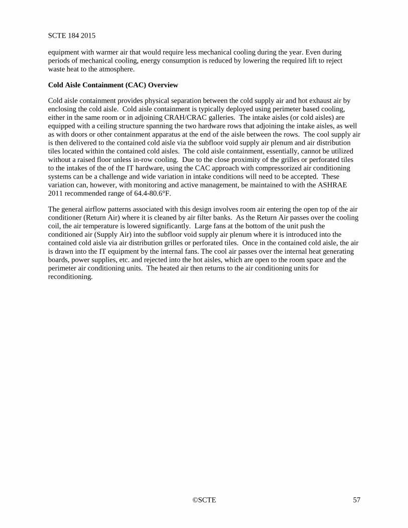
SCTE 184 2015
©SCTE 57
equipment with warmer air that would require less mechanical cooling during the year. Even during periods of mechanical cooling, energy consumption is reduced by lowering the required lift to reject waste heat to the atmosphere.
Cold Aisle Containment (CAC) Overview
Cold aisle containment provides physical separation between the cold supply air and hot exhaust air by enclosing the cold aisle. Cold aisle containment is typically deployed using perimeter based cooling, either in the same room or in adjoining CRAH/CRAC galleries. The intake aisles (or cold aisles) are equipped with a ceiling structure spanning the two hardware rows that adjoining the intake aisles, as well as with doors or other containment apparatus at the end of the aisle between the rows. The cool supply air is then delivered to the contained cold aisle via the subfloor void supply air plenum and air distribution tiles located within the contained cold aisles. The cold aisle containment, essentially, cannot be utilized without a raised floor unless in-row cooling. Due to the close proximity of the grilles or perforated tiles to the intakes of the of the IT hardware, using the CAC approach with compressorized air conditioning systems can be a challenge and wide variation in intake conditions will need to be accepted. These variation can, however, with monitoring and active management, be maintained to with the ASHRAE 2011 recommended range of 64.4-80.6°F.
The general airflow patterns associated with this design involves room air entering the open top of the air conditioner (Return Air) where it is cleaned by air filter banks. As the Return Air passes over the cooling coil, the air temperature is lowered significantly. Large fans at the bottom of the unit push the conditioned air (Supply Air) into the subfloor void supply air plenum where it is introduced into the contained cold aisle via air distribution grilles or perforated tiles. Once in the contained cold aisle, the air is drawn into the IT equipment by the internal fans. The cool air passes over the internal heat generating boards, power supplies, etc. and rejected into the hot aisles, which are open to the room space and the perimeter air conditioning units. The heated air then returns to the air conditioning units for reconditioning.
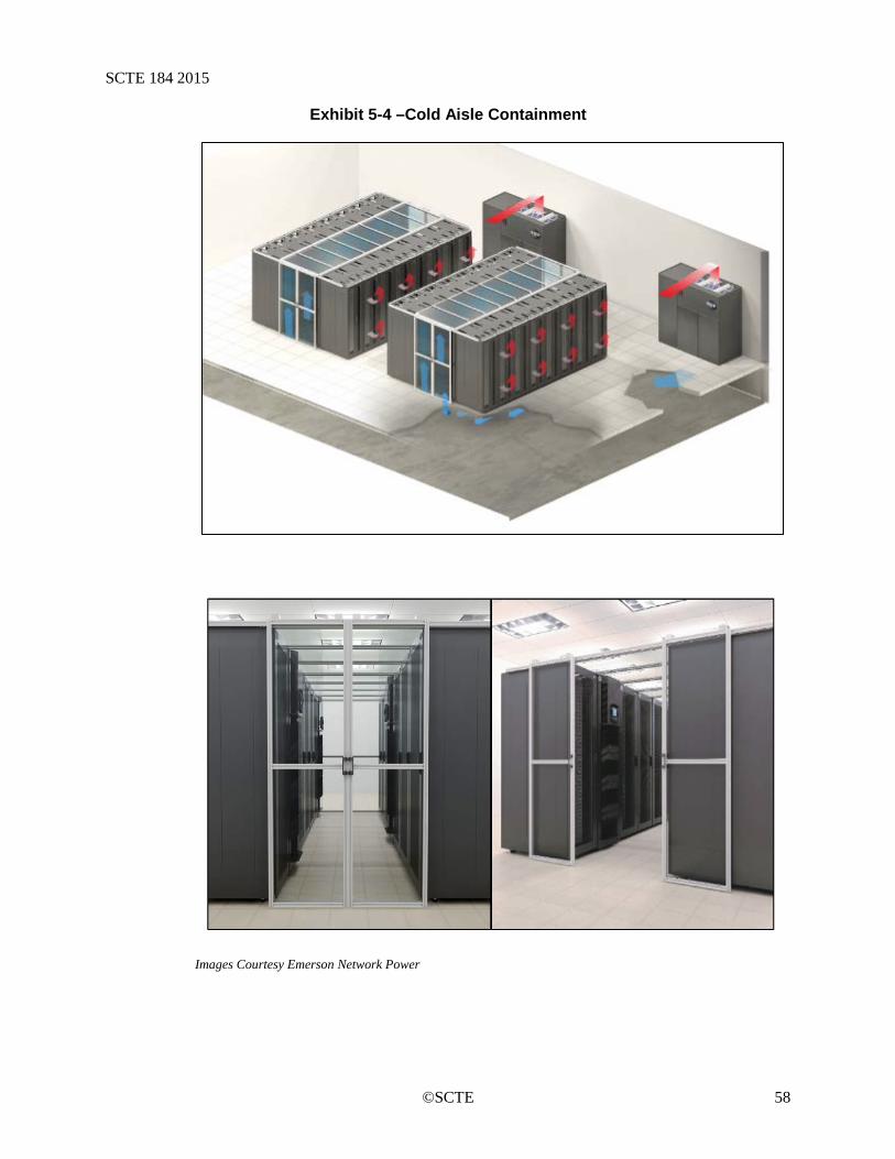
SCTE 184 2015
©SCTE 58
Exhibit 5-4 –Cold Aisle Containment
Images Courtesy Emerson Network Power

SCTE 184 2015
©SCTE 59
If in-row cooling is used, the airflow patterns change slightly. Room air (return) enters the back of the in-row coolers in the hot aisle. Return Air passes over the cooling coil, the air temperature is lowered significantly. Fans on the front of the in-row coolers push the conditioned air (Supply Air) into the cold aisle. The cool air passes over the internal heat generating boards, power supplies, etc. and rejected into the hot aisles, which are open to the room space. The heated air then returns to the in-row air conditioning units for reconditioning.
Exhibit 5-5: Cold Aisle Containment with In-Row Cooling
5.10. Cold Aisle Containment (CAC) Control Considerations
When using cold aisle containment, careful consideration must be given to the control scheme. Sensors location in the air conditioner return typical to the traditional data center cannot be effectively be utilized. Because the cold contained aisles become flooded with supply air, supply temperature becomes very important and must closely approximate the desired intake conditions. Two ways to accomplish this are supply-side control and intake control. Each of these methods can provide appropriate conditions but closely monitoring intake conditions is key to ensuring this. In addition to temperature control, there must also be control of the volumetric rate of the air conditioners. Controlling fan speeds to allow for the most energy savings, while still providing appropriate conditions to the IT hardware can be a very complex task.
When using supply side control, a sensor is extended from the perimeter (or gallery) located CRAC/CRAC under the raised floor plenum out to the area beneath the nearest cold aisle. The sensor is then set at or near the desired intake temperature level. Because the contained aisles are flooded with supply air and exhaust recirculation is kept to a minimum, there is very little stratification of temperatures. This means, that given a constant supply temperature, there can be little difference in intake temperature across the vertical face of the cabinets. Extensive monitoring of intake conditions
SCTE 184 2015
©SCTE 60
should accompany this design to ensure proper intake conditions are actually be supplied to the IT hardware
The intake control scheme typically uses a matrix of multiple sensors connected to each air handler. These sensors are extended out to the actual server cabinet front doors and attached. They are typically located at different heights on different cabinets through the rows. The control algorithm then averages the readings from all the sensors and uses the result to control supply condition of the CRAH / CRAC to which they are attached. While control method can employed in CAC, it is more often seen in Hot Aisle Containment and is discussed in more detail in the HAC section.
Controlling fan speed to allow for the most energy savings is very challenging in a CAC approach when using a raised floor. Ideally, in any containment approach, the ideal air conditioner volumetric rate of all units combined would be identical (or slightly more than) the volumetric rate of all IT hardware combined. Some of the hurdles in attaining this include air handlers not dedicated to a single cold aisle, different amount server volumetric rate in each cold aisle, and variable speed IT fans.
To better understand the challenges associated with CAC, one should understand the how this system would ideally be designed to operate. In this ideal scenario, with one CRAH and one contained cold aisle, differential pressure across the cold aisle doors would be used to control the CRAH volumetric rate to attain a slight positive pressure in the contained area. In addition, the CRAH would have a temperature sensors directly below the cold aisle set to the desired intake condition. The unit would deliver slightly more air than being moved by the servers, at the desired intake conditions. As IT hardware is added, or IT fan speed varies, the differential pressure gauge then varies the flow from the CRAH. This scenario, however, is not feasible in most IT space designs due to redundancy design limitations. When additional CRAH units and cold aisles are added, controlling across the cold aisle doors becomes less feasible.
One method often used is to control all CRAH fans together. This is accomplished by controlling all CRAH fans from the same point, or average of multiple points. Differential pressure between the subfloor void and the contained cold aisle can be used for this. Each cold aisle would have a single differential pressure sensor. These sensors would be networked and averaged to control all CRAH fan VSDs. This method, again, requires extensive monitoring of intake conditions. To manage the pressure across the cold aisle doors, the amount of free area (grilles or perforated tiles) in each cold aisle would need to be manually adjusted to ensure slight positive pressurization. With this manual aspect, there is no way to accommodate, IT equipment fan speed changes during operation. To ensure proper conditions at all time, the differential pressure across the cold aisle should be maintained at slight positive pressurization during peak demand times. The reduction in IT server fan speed during lesser demand would not be met by the CRAH fan speeds resulting in some inefficiency.
Electronically controlled dampers on air grilles can also be employed in the various control schemes to further improve energy efficiency of the CAC approach. But with this improved efficiency comes increased cost and complexity.
When in-row cooling is employed in a CAC, the airflow control is somewhat simplified. The temperature can be controlled by an array of sensors on the intakes of the server racks. The fan speed would then be controlled by differential pressure sensors across the doors of the containment area. Ideally, each of the in-row coolers would have their fan speed controllers linked together to operate in unison from the same pressure sensor.
These are only some of the control schemes that can be employed in a Cold Aisle Containment approach. Working closely with you design engineers and consultants is the best way to design and implement a control scenario that best needs of the overall design.
SCTE 184 2015
©SCTE 61
Benefits and Challenges of Cold Aisle Containment 5.10.1.
Some of the benefits of the Contained Cold Aisle include:
• Very fast response to temperature changes in the cold aisle. • Distributed / redundant cooling infrastructure. • Comfortable, moderate environment throughout in the cold aisle. • Increased energy savings, improved PUETM / CUE • Very consistent intake temperature levels are attainable with chilled water systems. • Can be retrofitted into a traditional perimeter air conditioning, raised floor IT space.
Some of challenges associated with Cold Aisle Containment include:
• Complex air conditioner fan controls. • Potentially uncomfortable temperature conditions in the majority of the room, outside the
cold aisles. • Standalone, non-rack mounted, IT hardware present significant installation and cooling
challenges. • May leave some energy savings opportunities underutilized. • Depending on local fire codes, may require additional, or more complex, fire detection
and suppression infrastructure.
The energy efficiency gains of utilizing a properly designed and controlled Cold Aisle Containment system are many and include reduced fan energy, ability to increase IT intake temperature, ability to increase chilled water temperature and increased free cooling window.
5.11. Hot Aisle Containment (HAC) Overview
Hot aisle containment is the physical separation between hot and cold air (intake and exhaust) by enclosing the hot aisle. HAC is also typically deployed using perimeter air conditioning and a raised floor plenum, although it offers more somewhat more design flexibility as compared to CAC. For example, a raised floor need not be used in the HAC system. As with CAC, an aisle is contained; however, as the name implies, it is the exhaust (or hot) aisle. Hot aisle containment can be accomplished in a similar manner to CAC, with end doors and a roof structure. However, HAC differs in that the contained aisle must be ducted to an overhead return plenum, such as a suspended ceiling void, or other duct system. Another method of hot aisle containment is Vertical Exhaust Duct Chimney Cabinets (VED). In this design, each cabinet is fitted with a solid rear door and a duct (or chimney) attached to the top of the cabinet and the overhead return plenum. Regardless of the hot aisle containment method chosen, the cold aisle remains open and part of the remainder of the room in the HAC approach.
The general airflow patterns associated with this design involve hardware exhaust leaving the IT equipment and entering the contained hot aisle (or the enclosed hardware cabinet in VED variant). The exhaust then enters the ceiling void return air plenum through ceiling grates (or chimney ducts in the VED variant). This return air then travels into to the top of the CRAH/CRAC units, also ducted to the ceiling void return plenum, where it is cleaned by air filter banks. Return Air passes over the cooling coil, the air temperature is lowered significantly. Large fans at the bottom of the unit push the conditioned air (Supply Air) into the subfloor void supply air plenum where it is introduced into the ambient space of the room through air distribution tiles. When a raised floor is not employed, supply is delivered to the ambient space directly from the air conditioning units.

SCTE 184 2015
©SCTE 62
Exhibit 5-6: Hot Aisle Containment
Exhibit 5-7: Hot aisle
If in-row cooling is used, the airflow patterns change slightly. Room air (return) enters the back of the in-row coolers in the contained hot aisle. Return Air passes over the cooling coil, the air temperature is lowered significantly. Fans on the front of the in-row coolers push the conditioned air (Supply Air) into the cold aisle, which is part of the overall room. The cool air passes over the internal heat generating boards, power supplies, etc. and rejected into the hot aisles. The heated air then returns to the in-row air conditioning units for reconditioning.
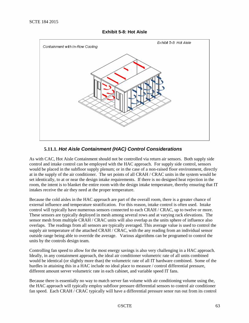
SCTE 184 2015
©SCTE 63
Exhibit 5-8: Hot Aisle
Hot Aisle Containment (HAC) Control Considerations 5.11.1.
As with CAC, Hot Aisle Containment should not be controlled via return air sensors. Both supply side control and intake control can be employed with the HAC approach. For supply side control, sensors would be placed in the subfloor supply plenum; or in the case of a non-raised floor environment, directly at in the supply of the air conditioner. The set points of all CRAH / CRAC units in the system would be set identically, to at or near the design intake requirements. If there is no designed heat rejection in the room, the intent is to blanket the entire room with the design intake temperature, thereby ensuring that IT intakes receive the air they need at the proper temperature.
Because the cold aisles in the HAC approach are part of the overall room, there is a greater chance of external influence and temperature stratification. For this reason, intake control is often used. Intake control will typically have numerous sensors connected to each CRAH / CRAC, up to twelve or more. These sensors are typically deployed in mesh among several rows and at varying rack elevations. The sensor mesh from multiple CRAH / CRAC units will also overlap as the units sphere of influence also overlaps. The readings from all sensors are typically averaged. This average value is used to control the supply air temperature of the attached CRAH / CRAC, with the any reading from an individual sensor outside range being able to override the average. Various algorithms can be programed to control the units by the controls design team.
Controlling fan speed to allow for the most energy savings is also very challenging in a HAC approach. Ideally, in any containment approach, the ideal air conditioner volumetric rate of all units combined would be identical (or slightly more than) the volumetric rate of all IT hardware combined. Some of the hurdles in attaining this in a HAC include no ideal place to measure / control differential pressure, different amount server volumetric rate in each cabinet, and variable speed IT fans.
Because there is essentially no way to match server fan volume with air conditioning volume using the, the HAC approach will typically employ subfloor pressure differential sensors to control air conditioner fan speed. Each CRAH / CRAC typically will have a differential pressure senor run out from its control
SCTE 184 2015
©SCTE 64
board to near the middle of an aisle. The set point on the air conditioners would then be set to the design subfloor pressure, for example 0.05” WC. The air distribution tiles would then be placed in the floor system. Ideally, the number would be the minimum necessary to provide the design goal temperature conditions to all IT equipment at all rack elevations. Adjustments in air distribution tile location should be made before adding air distribution tiles to address any hot spots, to ensure that the least fan energy is used to address intakes.
When in-row cooling is employed in a HAC, the airflow control is somewhat simplified. The temperature can be controlled by an array of sensors on the intakes of the server racks. The fan speed would then be controlled by differential pressure sensors across the doors of the containment area. Ideally, each of the in-row coolers would have their fan speed controllers linked together to operate in unison from the same pressure sensor. If the fans operate independently and are controlled on temperature, there is a potential for excess fan energy.
These are only some of the control schemes that can be employed in a Hot Aisle Containment approach. Working closely with you design engineers and consultants is the best way to design and implement a control scenario that best needs of the overall design.
Benefits and Challenges of Hot Aisle Containment 5.11.2.
Some of the benefits of the Contained Hot Aisle include:
• Reasonably fast response to temperature changes in the cold aisle. • Distributed / redundant cooling infrastructure. • Comfortable, moderate environment throughout in the cold aisle. • Comfortable, moderate conditions throughout the remainder of the room, outside of the hot
aisles. • Increased energy savings, improved PUETM / CUE • Reasonably consistent intake temperature levels are attainable with chilled water systems. • Can be retrofitted into a traditional perimeter air conditioning, raised floor IT space. • Standalone, non-rack mounted, IT hardware present can be installed in the open room.
Some of challenges associated with Cold Aisle Containment include:
• Complex air conditioner fan controls. • Potentially uncomfortable temperature conditions in the hot aisle. • May leave some energy savings opportunities underutilized. • Depending on local fire codes, may require additional, or more complex, fire detection and
suppression infrastructure. • Suspended ceiling or similar is required for return plenum. • High level of management of air distribution tiles if the most energy savings is to be attained • Non-rack mounted and standalone hardware may require additional management to ensure
exhaust enters return plenum.
The energy efficiency gains of utilizing a properly designed and controlled Hot Aisle Containment system are many and include reduced fan energy, ability to increase IT intake temperature, ability to increase chilled water temperature and increased free cooling window.
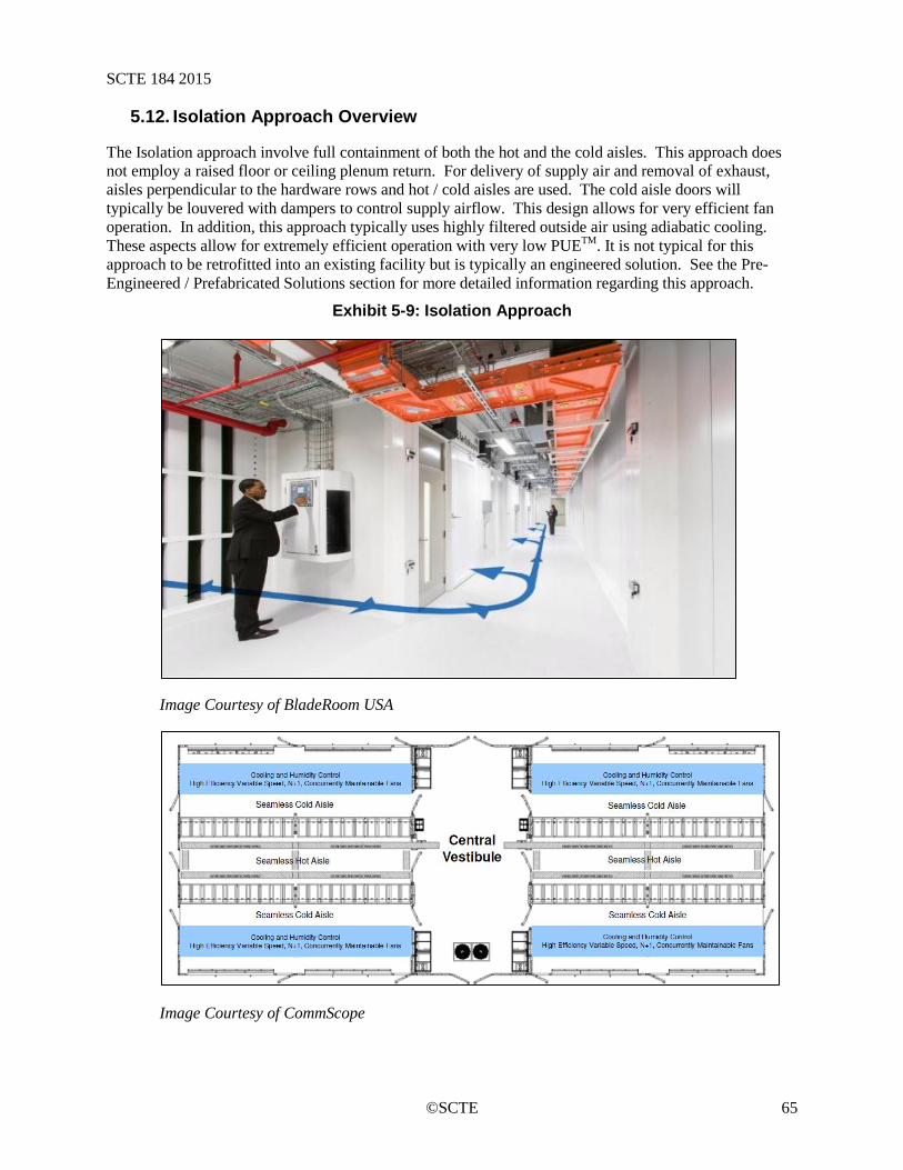
SCTE 184 2015
©SCTE 65
5.12. Isolation Approach Overview
The Isolation approach involve full containment of both the hot and the cold aisles. This approach does not employ a raised floor or ceiling plenum return. For delivery of supply air and removal of exhaust, aisles perpendicular to the hardware rows and hot / cold aisles are used. The cold aisle doors will typically be louvered with dampers to control supply airflow. This design allows for very efficient fan operation. In addition, this approach typically uses highly filtered outside air using adiabatic cooling. These aspects allow for extremely efficient operation with very low PUETM. It is not typical for this approach to be retrofitted into an existing facility but is typically an engineered solution. See the Pre-Engineered / Prefabricated Solutions section for more detailed information regarding this approach.
Exhibit 5-9: Isolation Approach
Image Courtesy of BladeRoom USA
Image Courtesy of CommScope
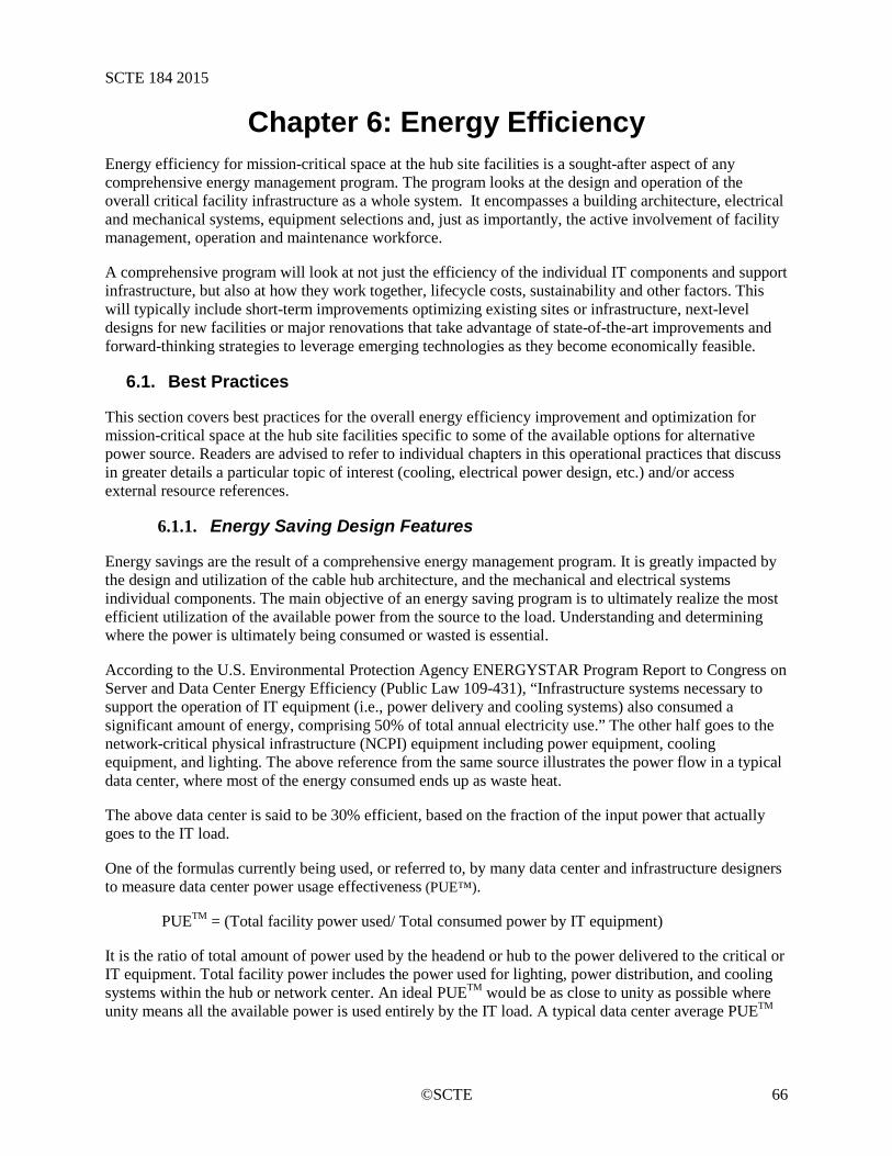
SCTE 184 2015
©SCTE 66
Chapter 6: Energy Efficiency Energy efficiency for mission-critical space at the hub site facilities is a sought-after aspect of any comprehensive energy management program. The program looks at the design and operation of the overall critical facility infrastructure as a whole system. It encompasses a building architecture, electrical and mechanical systems, equipment selections and, just as importantly, the active involvement of facility management, operation and maintenance workforce.
A comprehensive program will look at not just the efficiency of the individual IT components and support infrastructure, but also at how they work together, lifecycle costs, sustainability and other factors. This will typically include short-term improvements optimizing existing sites or infrastructure, next-level designs for new facilities or major renovations that take advantage of state-of-the-art improvements and forward-thinking strategies to leverage emerging technologies as they become economically feasible.
6.1. Best Practices
This section covers best practices for the overall energy efficiency improvement and optimization for mission-critical space at the hub site facilities specific to some of the available options for alternative power source. Readers are advised to refer to individual chapters in this operational practices that discuss in greater details a particular topic of interest (cooling, electrical power design, etc.) and/or access external resource references.
Energy Saving Design Features 6.1.1.
Energy savings are the result of a comprehensive energy management program. It is greatly impacted by the design and utilization of the cable hub architecture, and the mechanical and electrical systems individual components. The main objective of an energy saving program is to ultimately realize the most efficient utilization of the available power from the source to the load. Understanding and determining where the power is ultimately being consumed or wasted is essential.
According to the U.S. Environmental Protection Agency ENERGYSTAR Program Report to Congress on Server and Data Center Energy Efficiency (Public Law 109-431), “Infrastructure systems necessary to support the operation of IT equipment (i.e., power delivery and cooling systems) also consumed a significant amount of energy, comprising 50% of total annual electricity use.” The other half goes to the network-critical physical infrastructure (NCPI) equipment including power equipment, cooling equipment, and lighting. The above reference from the same source illustrates the power flow in a typical data center, where most of the energy consumed ends up as waste heat.
The above data center is said to be 30% efficient, based on the fraction of the input power that actually goes to the IT load.
One of the formulas currently being used, or referred to, by many data center and infrastructure designers to measure data center power usage effectiveness (PUE™).
PUETM = (Total facility power used/ Total consumed power by IT equipment)
It is the ratio of total amount of power used by the headend or hub to the power delivered to the critical or IT equipment. Total facility power includes the power used for lighting, power distribution, and cooling systems within the hub or network center. An ideal PUETM would be as close to unity as possible where unity means all the available power is used entirely by the IT load. A typical data center average PUETM
SCTE 184 2015
©SCTE 67
is between 2.0 to 2.5, representing substantial inefficiencies with an opportunity for more efficient power use.
Another alternative definition used by Energy Star is the Source PUETM. It is defined as:
• Source PUETM = Total Facility Energy (kWh)/UPS Energy (kWh)
The Energy Star definition provides a measure of data center infrastructure efficiency. It is important to note both definitions do not address the overall data center efficiency.
Consequently, an improvement in the design features and use of the hub critical infrastructure building blocks (architectural, mechanical, and electrical) systems components will greatly impact the overall energy saving objective.
Energy saving design feature good practices include:
a) Hub (building) architecture: A reduction in energy use can be realized by implementing good practices in building orientation, selection of low emission materials, cabinets and rack layouts, length and width of rack rows, and the placement of service platforms equipment within the allocated space.
b) Electrical system infrastructure: select the most efficient power transformation and distribution equipment, panel boards, switch gears, backup generators and cables available. Careful selection of these components at the design level will greatly impact the operating efficiencies of the entire electrical system.
c) Mechanical Cooling Systems: Heat is energy lost. Most mechanical designers focus their design on meeting a predetermined supply of cold air to maintain a certain temperature level within the hub. Pro-active consideration of an effective heat removal design at the planning stage will greatly improve the PUETM of the facility and enhance the energy saving objectives. A favorable PUETM can be obtained by observing the following:
• Maintain appropriate air distribution based on the cooling system employed. • Optimize the chilled air delivery system while constantly monitoring and maintaining an
efficient equipment to operable temperature and humidity range. • Reference Chapter 5 for additional information. • SOURCE: DOE-Federal Energy Management Program -white paper
Further information is available from U.S. Environmental Protection Agency ENERGY STAR Program Report to
Congress on Server and Data Center Energy Efficiency (Public Law 109-431)
Modular Data Center Design 6.1.1.1.
Modular and scalable design for critical spaces is trending to become the norm in response to the constant demand of effective use of, and the need for more space, power and cooling. These designs are customizable site specific solutions that can be used to meet existing or new cable headend facilities. The designs are typically complete with full consideration for network core and access platforms, power, cooling, racks, monitoring, fire and safety. A modular and scalable critical space design works best for a new site as it does not require detailed planning of future load and connectivity.

SCTE 184 2015
©SCTE 68
On-Site Generation 6.1.1.2.
Another alternative to power from the grid is on-site generation. It is a good solution for facilities with high demand for power and cooling. On-site energy generation using fuel cell or gas generators with a single fuel source such as natural gas or liquid hydrogen can be used to produce combined heat and power. Heat generated can be reclaimed for either heating or cooling the facility, reducing dependencies on utility grid while at the same time decreasing operating energy expenses.
Lighting 6.1.1.3.
Lighting is a major consumer of electricity for commercial buildings. In environments that require 24x7 operation and security such as cable headends and datacenters, adequate lighting is essential for remote monitoring via cameras. Several considerations should be made when reviewing lighting in the 24x7 space.
a) Types of Lighting: Three types of lighting is commercially available – LED, compact fluorescent, and fluorescent.
• LED traditionally will have the highest CAPEX price tag, however, LED presents several OPEX advantages in a 24x7 space: expected life of 50,000 hours compared to 5,000 for other lighting; watt consumption averaging 15 -20 watts/lamp vs. 38-40 for traditional linear fluorescent tubes. With fewer watts consumed and the light emitting diodes not creating light as a byproduct of heat, HVAC gains can be seen when choosing LED, along with a higher efficient power factor ratings up to 0.996%. When selecting LED lighting, it has been demonstrated by leading manufacturers that LEDs operation utilizing external power drivers provides advantages to linear tubes that require internal power drivers. The external driver advantage includes: removing additional heat source away from the circuit board (diodes) as heat is a major cause of failure; and if the driver should fail (the leading cause of LED failure is the power driver), the entire tube does not have to be replaced as the external driver can be serviced and the tube remain in service.
• Compact fluorescent (CFL) does provide lower watt consumption compared to traditional fluorescent tubes; however, in Greenfield installations, LED should be evaluated first. For existing structures, LEDs should strategically be worked into replacement budget cycles for the above mentioned advantages.
• Parking facilities are excellent candidates for LED installations as exterior lighting can depend on extremely high wattage lamps – 250, 400 and higher wattage. There are a number of commercially available products that can be retrofitted to existing lamps. One cautionary note, LED lighting is directional and care should be taken during site survey of parking facilities as to not create too many “black holes” or dark spots due to the directional beam limitations of the LED boards.
Energy Saving Operational Issues 6.1.2.
It is a generally accepted fact that the energy bill for a typical cable headend facility can account for as much as 10%-30% of a cable headend annual operating budget. Based on EPA data, roughly 50% of this can be allocated to infrastructure. Therefore, it is very critical for facility managers to adopt good energy saving practices. It may be cheaper to improve on the use of energy and become more efficient than to invest in more energy efficient systems.
SCTE 184 2015
©SCTE 69
The first and most important step in identifying and eliminating energy use operational issues is to establish an energy efficiency policy and a goal.
a) Monitor and enhance energy use effectiveness at all levels within the facility to isolate systems of high consumption and with room for optimization.
b) Determine site PUETM and strive to lower it by eliminating energy waste due to poor and less efficient power distribution and cooling.
c) Conduct a facility audit to determine power and cooling specifications for the hub service platform equipment.
Use best practices in temperature and thermal guidelines such as ASHRAE to maintain proper cooling temperature at the equipment inlet.
• SOURCE: DOE-Federal Energy Management Program -white paper
d) Improve under floor air distribution by removing unused legacy cables and minimizing cable congestion.
e) Remove decommissioned servers and/or consolidate equipment to minimize phantom power use.
f) Retrofit the lighting system with a more efficient one. A wide variety of highly efficient light sources are currently available, including fluorescent (linear and compact), high-intensity discharge (HID), and newer sources such as induction lamps and light-emitting diodes (LEDs).
g) Retrofit existing and less efficient air conditioning units with compressor monitoring and a control system that is readily available in the market. This system will enhance the operation of a dual compressor system by commanding individual or both compressors to come on based on the heat load.
h) Installing Variable Speed Drives (VSD) on units where applicable. VSDs operate and control motor operation according to the actual load needs, whereas a motor without a VSD will operate continuously at full speed regardless of load.
Future Planning 6.1.3.
When planning for replacement of all the materials that are involved in the 24x7 ecosystem, it is important to leverage current technologies that are either EPA Energy Star rated or adhere to SCTE Product Environmental Requirements for Cable Telecommunications Facilities. These standards, when considered in their entirety, should serve as an excellent guide for new build outs and/or lifecycle management considerations as materials come up for replacement.
Power Utilization Effectiveness (PUETM) 6.1.3.1.
PUETM is a registered or unregistered trademarks and/or service mark of The Green Grid Association or their respective owners in the United States and/or other countries. PUETM is the leading metric used to show how efficiently data centers are using energy. PUETM is the ratio of how much energy consumption is used to run a data center’s IT and servers compared to how much energy is needed to operate the overall data center. If very little of a data center’s energy is used for cooling and power conversion (and is instead mostly being used to power its servers), a data center is using energy much more efficiently and will have a PUETM closer to one. By comparison if more of the energy consumed by a data center or critical IT space is used for cooling and power conversion, the energy use isn’t as efficient, and the data center will have a higher PUETM.
SCTE 184 2015
©SCTE 70
How and where the energy consumption measurements are taken, and what parts of the energy consumed constitute facility power or IT power have been the subject of great industry debate. Many public companies publish gaudy PUETM figures suggesting that these facilities are extremely efficient. However, the data behind this PUETM figures is often not published and considered proprietary. Thus comparing PUETM data of other companies to one’s own facilities is often an exercise in futility. PUETM is best used to compare similar facilities across a business, and to compare ongoing PUETM figures within a facility to track improvements and seasonal influence, using known and consistent measuring points and similar calculation models.
Consideration and care must also be taken when evaluating PUETM improvements as they may not always reflect actual energy savings. For example, many servers and other IT equipment are equipped with variable speed fans. When cooling infrastructure fan speeds are reduced in an effort to save energy, the variable speed fans within the IT equipment may increase speed to maintain the manufacturer predetermined temperature delta across the chips sets. This increases the IT equipment load while reducing HVAC load. This may result in no real energy savings, or may actually increase energy use, while indicating an improved PUETM. Another area where caution should be applied is during virtualization. When servers are virtualized, or platforms combined, actual IT energy and facility energy is saved; however, PUETM may increase (worsen). These increases occur because as facility load decreases, infrastructure efficiency may then decrease.
Carbon Usage Effectiveness (CUE) 6.1.3.2.
This metric was also created by The Green Grid and similar to PUETM, the CUE metric looks at the carbon emissions associated with operating a data center (not its construction). More specifically, the CUE is a ratio of the total carbon emissions due to the total energy consumption of the data center compared to the energy consumption of the data center’s servers and IT equipment. The metric is expressed in kilograms of carbon dioxide (kg CO2eq) per kilowatt-hour (kWh), and if a data center is 100-percent powered by clean energy, it will have a CUE of zero. The CUE could one day be a particularly important metric if there is a global price on carbon. However, significant industry standardization in measurement and tracking would need to be put in place. At its current state, CUE presents the same limitation described above for PUETM.
Water Usage Effectiveness (WUE) 6.1.3.3.
Also created by The Green Grid, it calculates how efficiently a data center is using water. Data Center water use is primarily from large chiller systems that utilize water cooling towers to reject heat absorbed from the environmentally controlled space and chiller. Cooling towers are heat rejection devices that reject heat into the atmosphere through evaporation. As heat is rejected into the atmosphere and water is evaporated the water level in the cooling tower drops. More water is added to the cooling tower and circulating water system in order to compensate for the water losses from evaporation. WUE is a ratio of the annual water Cooling towers are often shared by a mixed use building where the data center is housed, making the calculation of WUE difficult.
Because a WUE of zero is considered ideal, this often reflects poorly on free cooling methods that employ evaporation to save energy in mechanical cooling such as adiabatic cooling and indirect or direct evaporative systems. Compromises and trade-off must be considered for improvements to PUETM and CUE usage to how much energy is being consumed by the IT equipment and servers, and is expressed in liters/ kilowatt-hour (L/kWh). Like CUE, the ideal value of WUE is zero, representing no water used to operate the data center.
SCTE 184 2015
©SCTE 71
Carbon Intensity per Unit of Data 6.1.3.4.
Many companies have been measuring the carbon emissions related to their computing operations in the metric of “CO2 per megabytes of data delivered.” Establishing this metric enables companies and their customers to compare computing energy usage across their industry. Some companies are making this metric available on a monthly basis to their customers.
PAR4 6.1.3.5.
This metric was developed by startup Power Assure. The PAR4 methodology takes four measurements of the equipment to obtain real-world power consumption figures: when the equipment is off, idle, loaded and at peak. With these measurements, PAR4 calculates the transactions per second per watt (Tps/W) at 100% load. The PAR4 numbers can then be used for accurately planning the maximum power allocation.
Essentially, PAR4 enables servers of different makes, models and generations to be compared to one another in terms of energy efficiency.
Chapter 7: Contaminant Management Airborne and settled contaminants can impact both hardware reliability and efficiency of mechanical systems.
Destructive interactions between airborne particulate and electronic instrumentation can occur in numerous ways. The means of interference depends on the time and location of the critical incident, the physical properties of the contaminant, and the environment in which the component is placed. Examples include physical interference, corrosive failures, shorts or heat failures.
Impact on energy efficiency can also be realized where contaminant infiltration leads to conditions that impact airflow through filters, or where contaminant deposits on air intakes to hardware are impeded. Where excessive settled deposits are present, they can impact thermal dissipation properties of the hardware components. Consideration during design and maintenance of the facility and support systems and control of personnel practices are necessary for control of contaminants in the critical space.
• SOURCE: ASHRAE - 2011 Gaseous and Particulate Contamination Guidelines For Data Centers, Whitepaper prepared by ASHRAE Technical Committee (TC 9.9 Mission Critical Facilities, Technology Spaces and Electronic Equipment, 2011.
7.1. Best Practices
The following general best practices are defined based on their value in providing opportunities for energy efficiency while still maintaining base requirements for availability, maintainability and security.
Recommended Air Quality Levels 7.1.1.
International Standard ISO 14644 is most widely recognized and is referenced in BS 7083 and other international standards. US Federal Standard 209E, developed by the Institute of Environmental Sciences and Technology, as of November 2001 has been superseded by ISO 14644. ISO 14644 is similar to US Federal Standard 209E and is considered an evolution of that standard. The ISO standard is used and recognized by hardware providers, data center designers and industry groups worldwide.
SCTE 184 2015
©SCTE 72
ISO 14644 is divided into numerous Airborne Particulate Cleanliness Classes. One of the least stringent classes, Class 8, is generally accepted as an appropriate measure of critical IT spaces environments. For comparison purposes, it is noted that ISO 14644, Class 8 is very similar to US FED-STD-209E, Class 100,000.
• SOURCE: ISO 14644 - Cleanrooms and associated controlled environments. 2004
Contaminant Effects 7.1.2.
ASHRAE Particulate and Gaseous Contamination Guidelines for Data Centers describes the, “need to control airborne contaminants, both particulate and gaseous, in data centers and to specify their recommended acceptable limits.” It identifies three main categories of contaminant effect: chemical, mechanical and electrical. The most recent revision includes additional information on the importance of designing facilities to minimize contaminant influence and ensuring that operations manage contaminant concerns so as to reduce their potential impact on hardware availability.
• SOURCE: ASHRAE - 2011 Gaseous and Particulate Contamination Guidelines For Data Centers, Whitepaper prepared by ASHRAE Technical Committee (TC 9.9 Mission Critical Facilities, Technology Spaces and Electronic Equipment, 2011.
External Influences 7.1.3.
External contaminant influences are a concern due to the potential impact on hardware operations, but they are also an indicator of exposures that can impact requirements for mechanical environmental controls. Expanding exposure to outside conditions in the interest of expanding free-cooling windows or taking advantage of other energy savings initiatives should not inappropriately compromise conditions that can impact IT availability. The ROI evaluation of every energy efficiency initiative should properly weigh the cost and impact of all controls necessary for required availability.
Operator Activity 7.1.4.
Operator activity within the data center should be limited. Human movement within the computer space is a significant source of contamination. Contaminants from personnel within the equipment room such as dust, hair, skin, clothing fibers, etc., can contribute to overall contamination. Additionally, settled contamination already present in the site can become disturbed and enter the supply airflow to equipment in the ambient space by as little action as walking across the floor. Food and drink should never be allowed in the controlled space.
A dedicated area should be set aside outside the controlled space for staging, unpacking and environmental acclimation of the hardware. The environment in this area should be the same as the equipment room, but isolated from it. Storage and handling of unused equipment or supplies can be a source of contamination, and can lead to unnecessary personnel traffic and associated exposures, impacting environmental control requirements and associated energy usage.
Cleaning Practices 7.1.5.
Inappropriate cleaning practices can degrade the environment. Many chemicals used in normal or office cleaning applications can damage sensitive computer equipment. Out-gassing from these products or direct contact with hardware components can cause failure. Certain biocide treatments used in building air handlers are also inappropriate for use in computer rooms. They contain chemicals, which can degrade components and are not designed to be used in the airstream of a recirculating air system. The use of push mops or inadequately filtered vacuums can also stimulate contamination.
SCTE 184 2015
©SCTE 73
Provide quarterly site cleaning utilizing a specialized cleaning contractor. Provide three (3) above floor cleanings and one (1) above and below floor cleaning (as applicable) yearly.
Filtration 7.1.6.
Air introduced into the hardware space can be a source of contamination. Inadequately filtered air from outside the controlled environment can introduce innumerable contaminants. Post-filtration contamination in ductwork can be dislodged by airflow and introduced into the hardware environment. Air entering the critical space should; ideally, be filtered by a minimum of MERV 13 (ASHRAE 80% to 90%) to control contaminant infiltration.
Ensure that adjoining businesses, are not generating harmful chemicals that could be ingested by the site external air system. Examples are: dry-cleaning establishments, restaurant kitchens, refineries, etc. If in doubt, a risk assessment should be conducted to determine if gas filtration media is required on the external air system.
• SOURCE: BICSI Data Center 002-2010 – Data Center Design and Implementation Best Practices (Environmental Conditions). Jun 2010
• SOURCE: ASHRAE Design Considerations for Datacom Equipment Centers, 2005 • SOURCE: ASHRAE - 2011 Gaseous and Particulate Contamination Guidelines For Data Centers,
Whitepaper prepared by ASHRAE Technical Committee (TC 9.9 Mission Critical Facilities, Technology Spaces and Electronic Equipment, 2011.
Chapter 8: Fire, Safety & Security Protection against fire, safety hazards and security threats is an important aspect of the design and ongoing maintenance of the critical space.
The most common sources of fires in critical IT spaces are related to the electrical system, the hardware, or risk associated with adjacent non-related areas. Breakdowns in insulation and the resultant short-circuiting can lead to intense heat, which can melt materials or cause a fire. Such fires are often small or smoldering with little effect on the temperatures in the room. Because the smoke itself can impact the computer hardware, it is necessary to employ a detection system which is sensitive to smoke and other products of combustion rather than temperature. The specific detection and extinguishing system is dependent on the particular design and exposures of the individual data center area.
Physical security of the critical space is also extremely important. Access must be controlled to limit the possibility of accidental or designed interference with data operations. The computer hardware is a tremendous investment and the cost of downtime is often incalculable.
The facility should include both detection of the threats as well as protection against their influence. The manner in which the facility will be designed and operated will be influenced by local conditions, but some general best practices are applicable at most sites. In all cases, compliance with local codes is a requirement.

SCTE 184 2015
©SCTE 74
8.1. Best Practices
Fire Detection 8.1.1.
Automatic photoelectric, laser spot or similar detectors should be installed in the critical space to provide early warning of fire. These detectors should provide local alarming and be integrated into remote alarm monitoring and notification.
The detectors should be installed throughout the critical space. Detectors should also be installed in the ceiling void and/or subfloor void as appropriate to room design and local Codes.
Resource: NFPA 75, 6-2.1, 1999
All detection equipment should be installed and maintained in accordance with NFPA 72, National Fire Alarm Code®, and must meet all national and local codes.
Fire Suppression 8.1.2.
A passive suppression system reacts to detected hazards with no manual intervention. The most common forms of passive suppression are sprinkler systems or chemical suppression systems.
Where sprinkler systems are used, a pre-action design is preferable. Pre-action systems will flood the sprinkler pipes upon an initial detection but will have a delay before actual discharge; thus, incorporating a degree of protection against leaks or accidental discharge while still providing rapid response to a fire event.
• SOURCE: ASHRAE Design Considerations for Datacom Equipment Centers, 2005
A total flooding agent chemical suppression system, both above & below the raised floor, provides comprehensive protection of the critical space without the same threat of damage to the hardware that is posed by a water sprinkler. This type of system should be used in computer and communications hardware areas and other selected critical areas where water systems are not feasible, or where the value of the hardware and ability to return the room to operations quickly after an event justifies the expense.
The actual suppression agent should be selected after review of the most up-to-date regulations, including pending and draft regulations concerning possible environmental restrictions. Although FM200 (HFC227ea) is currently the most popular choice, and has an ozone depletion potential of zero, concerns have been raised about the GWP (Global Warming Potential) of HFCs. This concern may ultimately result in regulation that limits, or bans, its use in the future, resulting in a possible expensive retrofit.
The gas suppression system should deactivate the HVAC equipment at 24x7 manned facilities prior to release of gas to limit spread of contamination and not add to the fire situation. In unmanned facilities, it is acceptable to have the AC systems operate after a gas release as long as the system is designed to do so. Gas suppression systems should not deactivate any electrical system unless mandated by local authority.
Extinguishers should be provided throughout the building as required by local authority. The extinguishers should be wall mounted and properly identified with brightly illustrated signs mounted so that they can be seen over the highest pieces of equipment in the room. In raised floor environments, tile lifting devices should be positioned at every fire extinguisher location. Daily use of lifting devices should be discouraged by signage or enclosed cases designating emergency use only.
• SOURCE: Article 100.7.3 of the 1994 Uniform Fire Code
SCTE 184 2015
©SCTE 75
Personnel Safety Practices & Precautions 8.1.3.
The most important safety precautions that can be taken in an equipment room are to limit the number of personnel in the sensitive areas to the absolute minimum, and ensure that all personnel are fully trained to respond to emergency situations.
Manual controls for the various support systems in the equipment room should be located conveniently in the room. Ideally, fire, leak detection, HVAC, power and abort or silence controls and an independent phone line should all be grouped by the appropriate doors. All controls should be clearly labeled and concise operating instructions should be available at each station. Where present, Emergency Power Off (EPO) and fire suppression release buttons should be protected from accidental triggering.
Positive Pressure Environment and Occupant Ventilation 8.1.4.
If the critical space is cooled by 100% recirculation air conditioning units, a minimum amount of make-up air from outside the critical space should be considered for ventilation and positive pressurization purposes. Ventilation for the human occupants of the data center should be assessed and adjusted as changes in room design or procedures dictate and should always meet applicable local codes. Maintaining a positive pressure in the critical space will limit exposure to lesser controlled adjoining areas through gaps and breaches in the environmental envelope of the space. Introduction should be kept to the minimum necessary to avoid inappropriate influence on the environmental control systems, as this could cause them to operate unnecessarily and inefficiently.
Water Detection 8.1.5.
Water detection is important for a number of reasons. Leaks in the critical space can cause serious threats to both personnel and hardware. Leaks are indicative of inappropriate functioning or conditions of the building structure or infrastructure.
Physical Security 8.1.6.
In facilities where the critical space is located on an exterior wall, the walls should be concrete and rebar void filled concrete masonry unit construction (200 mm thick) or better. Ducts entering protected spaces (to include building perimeters) should be protected with burglar bars to preclude intrusion. Burglar bars should be of substantial construction to preclude entry via HVAC ducts greater than 240 square centimeters (with any dimension being greater than 15 centimeters).
All ingress points to the facility housing the critical facility should be monitored and controlled with an access control system. Door exit sensors should be provided to allow alarm free passage from protected areas. No windows are permitted into this space.
Security Systems 8.1.7.
Proactive security measures should be put in place to secure the critical space and minimize threats. This includes precautions such as:
• Perimeter fencing & no exterior signage • Protected infrastructure areas with fencing, security grills and locked fuel supply • Separation of parking from the building structure and/or bollards • Exterior & Interior CCTV monitoring with 24/7 recording & associated lighting • Building and room proximity card access, with alarm and recording system
SCTE 184 2015
©SCTE 76
Monitoring & Response 8.1.8.
In addition to local and direct-to-responder monitoring, alarm and messaging, it is essential that all critical spaces be adequately integrated into the Network operations Center (NOC) or similar centralized monitoring & response center. This is particularly important for remote or unmanned sites. Additional information and recommendations can be found in Chapter 9: Environmental Monitoring & Building Management.
Chapter 9: Environmental Monitoring & Building Management
Environmental Monitoring and Building Management Systems (BMS) are typically computer-based Direct Digital Control (DDC) systems that are found more often in larger buildings. They can also be found in smaller buildings but are often scaled down systems with less functionality, control and monitoring capabilities. BMS’s are designed to control and monitor the building’s mechanical and electrical equipment including Electrical Distribution Systems, Mechanical Systems such as Heating, Ventilation and Air Conditioning, Fire Detection System, Fire Suppression System, and sometimes Security and Card Access Systems.
Primary functions of the BMS include controlling and monitoring the operations, performance and status of the systems and system components of building systems including maintaining the desired environmental conditions of space temperature and humidity set points. The BMS maintains the desired space temperature and humidity set points by controlling the heating, cooling, humidification and dehumidification systems, managing the distribution of air to people and equipment space by modulating outside air, return / mixed air and supply air dampers. The BMS may also be used to control indoor or under floor static pressure, monitoring and controlling indoor air quality, and controlling CO2 levels.
Additional functionality of a BMS includes controlling, monitoring and reporting the status of the electrical distribution system and the electrical distribution components including utility power availability, main switchgear – Automatic Transfer Switch (ATS), generator, Uninterruptable Power Supply (UPS), Static Transfer Switch (STS) and Power Distribution Units (PDU). Indoor and outdoor lighting can be controlled utilizing on/off schedules that mirror occupancy. Lights are turned on when buildings are occupied and turned off when they are unoccupied.
The communications network or backbone of the BMS can be constructed with twisted pair copper wire or fiber. Retrofitted systems may contain pneumatic components. Twisted pair copper is often used in smaller systems that have a minimum number of devices being monitored or controlled. Twisted pair backbones are less expensive, but have limitations with data processing speed and data capacity. If a balanced twisted pair copper cabling backbone is installed, the minimum standard wire should be 6A. Category 6A cabling for an entire network will improve support for higher data rate applications.
BMS fiber backbones are typically installed in larger systems that monitor and control large, complex building systems. Primary advantages for installing fiber backbones are data processing speed and data processing capacity. OM4 laser optimized multimode fiber can support higher speed applications while also providing backward compatibility to most existing applications. However, fiber backbones may be more expensive due to the media conversion devices required to convert fiber technology to copper technology and copper technology to fiber technology.
Building Systems that are controlled and monitored by the BMS are typically the largest consumers of power or energy within the building. Therefore, they are an integral part of controlling and reducing

SCTE 184 2015
©SCTE 77
utility costs and operating expenses. Installed, maintained and operated correctly, the BMS can optimize energy efficiency without impacting comfort or reliability.
9.1. Best Practices
The following general best practices are defined based on their value in providing opportunities for energy efficiency while still maintaining base requirements for availability, maintainability and security.
Building Management Systems 9.1.1.
As with all Capital expenditures specifying and installing a BMS requires a detailed financial analysis – identifying the type of system and functionality that will provide the best Return on Investment (ROI) is imperative. If Capital funding is not available for installing a complete system, then consideration should be given to installing a scalable system that can be supplemented when capital funds do become available.
Small scale BMSs should be designed to control and monitor the most critical building systems including power systems, cooling and heating systems, security systems, fire detection, and fire suppression systems as well as provide real time and historical energy efficiency data. Small scale BMSs are suitable for the multitude of smaller headend and hub sites, which, in aggregate, use a large percentage of the overall MSO facility energy. A few well placed, inexpensive power sensors will give a comprehensive picture of the energy usage profile of a site and can be used to track and manage energy efficiency such as PUETM.
Full scale BMSs are often found in larger and newer headends or mission-critical sites such as data centers. Similar to small scale BMSs, these systems should be designed to control and monitor the most critical building systems including power systems, cooling and heating systems, security systems and fire systems as well as provide real time and historical energy efficiency data. They should also provide additional operability and functionality to include control and monitoring of lighting systems, exhaust fans, and other non-critical equipment.
Building system components or points that should be monitored and controlled include:
Electrical System 9.1.2.
• Utility Power • Generator • Main Switchgear/Automatic Transfer Switch (ATS) • HVAC distribution switchgear • UPS – kW & maintenance bypass • Static Transfer Switch (STS) • Power Distribution Units (PDU) /Remote Power Centers (RPC) • Emergency Power Off (EPO) • Power Strip • Receptacle / Outlet
Mechanical System 9.1.3.
• Chiller • On/Off Status • Chilled Water Supply Temperature • Chilled Water Return Temperature
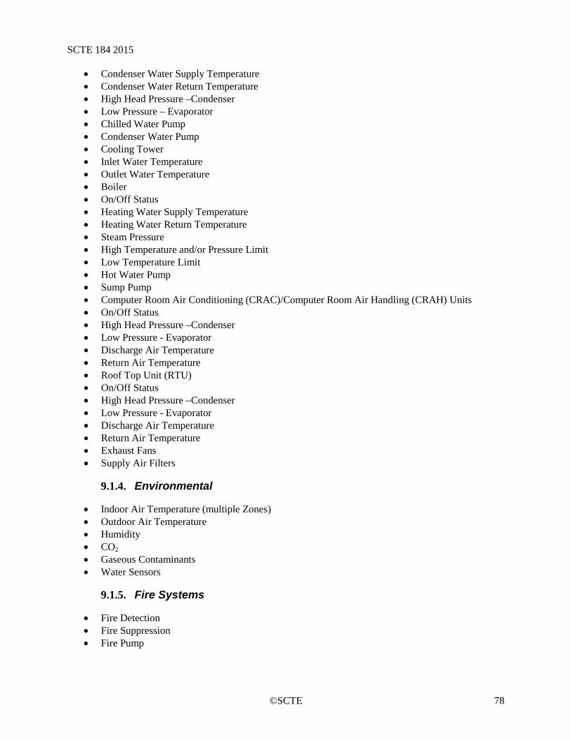
SCTE 184 2015
©SCTE 78
• Condenser Water Supply Temperature • Condenser Water Return Temperature • High Head Pressure –Condenser • Low Pressure – Evaporator • Chilled Water Pump • Condenser Water Pump • Cooling Tower • Inlet Water Temperature • Outlet Water Temperature • Boiler • On/Off Status • Heating Water Supply Temperature • Heating Water Return Temperature • Steam Pressure • High Temperature and/or Pressure Limit • Low Temperature Limit • Hot Water Pump • Sump Pump • Computer Room Air Conditioning (CRAC)/Computer Room Air Handling (CRAH) Units • On/Off Status • High Head Pressure –Condenser • Low Pressure - Evaporator • Discharge Air Temperature • Return Air Temperature • Roof Top Unit (RTU) • On/Off Status • High Head Pressure –Condenser • Low Pressure - Evaporator • Discharge Air Temperature • Return Air Temperature • Exhaust Fans • Supply Air Filters
Environmental 9.1.4.
• Indoor Air Temperature (multiple Zones) • Outdoor Air Temperature • Humidity • CO2 • Gaseous Contaminants • Water Sensors
Fire Systems 9.1.5.
• Fire Detection • Fire Suppression • Fire Pump

SCTE 184 2015
©SCTE 79
Security / Card Access Sump Pump Energy Efficiency 9.1.6.
Power Utilization Effectiveness (PUETM)
Design Criteria and Certifications 9.1.7.
Design criteria and certifications provide definition and consistency for repeatable implementation of tested best practices.
• LEED – Leadership in Energy and Environmental Design. Some data center builders and operators are looking to the LEED building standard to prove their data centers are green. The strength of LEED is that it takes a holistic approach to evaluating the green credentials of a building, and considers materials, location, water use and indoor environmental air quality, along with energy efficiency. Buildings that achieve enough points under these five categories are certified by the U.S. Green Building Council.
• Energy Star. The Environmental Protection Agency’s Energy Star certification, which is widely used for electronics and personal computers, can also be used for stand-alone data centers and buildings that house large numbers of data centers. If a data center ranks in the top 25 percent of their peers in the EPA’s rating system, which has been in the works for years and is based on PUETM, then it can get an Energy Star label.
• ASHRAE. The American Society of Heating, Refrigerating and Air-Conditioning Engineers (ASHRAE) updated the “90.1 building efficiency standard” for data centers. Revisions were also made to the ASHRAE Thermal Guidelines for Data Processing Environments to accommodate a wider range for hardware operations and definitions of different classes of facility.
Local Facility Alarming 9.1.8.
Building Management Systems (BMS) can provide immediate notification of operational abnormalities.
Local facility alarming includes reporting alarm conditions for stand-alone, non-web based BMSs. They are classified as “local” because the alarms are only broadcast to the internal core management or maintenance personnel of the Building. The alarm reporting can be dispatched via cell phone, pager, e-mail, or onsite personnel including building engineers or security personnel. It is recommended that multiple building personnel receive the alarm notifications to assure adequate coverage and response.
Alarms are generated due to a change of state (on to off or off to on), due to conditions that are outside the normal operating range (pressure, temperature or humidity) or due to failure of systems or their components. Building system components that should be alarmed include, but are not limited to, Electrical System Components, Mechanical System Components, Environmental, Fire Detection, Fire Suppression, and Security. A detailed list of alarm points can be found in the best practices section.
Alarm notifications can be simple such as Chiller 1 Off, RTU 2 Hi Temp, Utility Power Off, Generator 1 Run, etc. or can be somewhat complex which requires deciphering such as CHLR1 Off, RTU2 HiTemp, UtilOff, Gen1Run. Regardless of the type of notification, alarming provides an immediate notification of abnormalities.
Multi-Site Monitoring Systems 9.1.9.
Facility management, data center management and real estate management companies that have multi-building portfolios often have multi-site monitoring systems. Multi-site monitoring systems include local, stand-alone systems that can be monitored individually or collectively and can be accessed locally or remotely through a web based architecture.

SCTE 184 2015
©SCTE 80
Multi-site monitoring systems can monitor and dispatch alarm notifications locally through audible means or via cell phone, pager or e-mail to on-site personnel including building engineers or security personnel or the alarms can be dispatched remotely to on-call personnel, to an operations center or to an alarm monitoring site. Personnel or vendors can then be dispatched to investigate the alarm and take corrective action to fix the problem. It is recommended that multiple building personnel receive alarm notifications to assure adequate coverage and response.
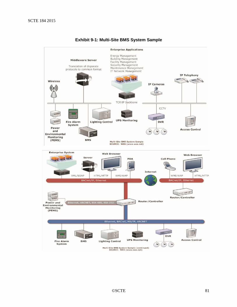
SCTE 184 2015
©SCTE 81
Exhibit 9-1: Multi-Site BMS System Sample
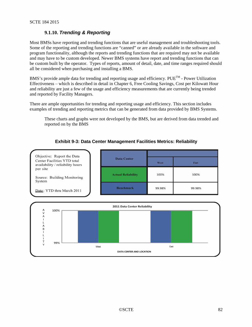
SCTE 184 2015
©SCTE 82
Trending & Reporting 9.1.10.
Most BMSs have reporting and trending functions that are useful management and troubleshooting tools. Some of the reporting and trending functions are “canned” or are already available in the software and program functionality, although the reports and trending functions that are required may not be available and may have to be custom developed. Newer BMS systems have report and trending functions that can be custom built by the operator. Types of reports, amount of detail, date, and time ranges required should all be considered when purchasing and installing a BMS.
BMS’s provide ample data for trending and reporting usage and efficiency. PUETM - Power Utilization Effectiveness – which is described in detail in Chapter 6, Free Cooling Savings, Cost per Kilowatt Hour and reliability are just a few of the usage and efficiency measurements that are currently being trended and reported by Facility Managers.
There are ample opportunities for trending and reporting usage and efficiency. This section includes examples of trending and reporting metrics that can be generated from data provided by BMS Systems.
These charts and graphs were not developed by the BMS, but are derived from data trended and reported on by the BMS
Exhibit 9-3: Data Center Management Facilities Metrics: Reliability
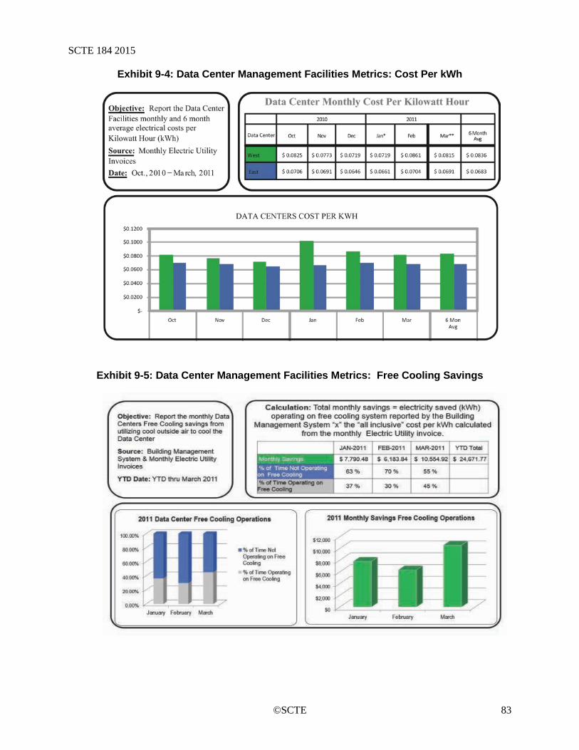
SCTE 184 2015
©SCTE 83
Exhibit 9-4: Data Center Management Facilities Metrics: Cost Per kWh
Exhibit 9-5: Data Center Management Facilities Metrics: Free Cooling Savings
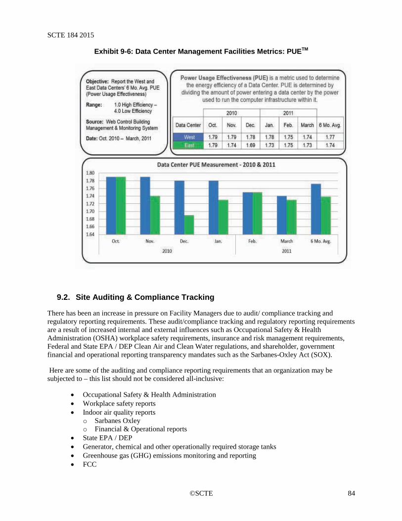
SCTE 184 2015
©SCTE 84
Exhibit 9-6: Data Center Management Facilities Metrics: PUETM
9.2. Site Auditing & Compliance Tracking
There has been an increase in pressure on Facility Managers due to audit/ compliance tracking and regulatory reporting requirements. These audit/compliance tracking and regulatory reporting requirements are a result of increased internal and external influences such as Occupational Safety & Health Administration (OSHA) workplace safety requirements, insurance and risk management requirements, Federal and State EPA / DEP Clean Air and Clean Water regulations, and shareholder, government financial and operational reporting transparency mandates such as the Sarbanes-Oxley Act (SOX).
Here are some of the auditing and compliance reporting requirements that an organization may be subjected to – this list should not be considered all-inclusive:
• Occupational Safety & Health Administration • Workplace safety reports • Indoor air quality reports
o Sarbanes Oxley o Financial & Operational reports
• State EPA / DEP • Generator, chemical and other operationally required storage tanks • Greenhouse gas (GHG) emissions monitoring and reporting • FCC
SCTE 184 2015
©SCTE 85
• Equal access requirements • Antenna Electro-Magnetic Radiation (EMR) studies and reports • Insurance/Risk Management inspections & reports • City/Municipal • Elevator Inspections • Domestic water back flow preventer inspections and reports • Fire Prevention / Life Safety • Fire Department/Fire Inspector assessments and reports • Health Department • Internal Company • Phase 1 & 2 Environmental audits • Safety & Fire Inspections
With the increase in audit/compliance tracking and regulatory reporting requirements comes an increased potential that an audit, inspection or report filing due date could get missed. This could create a non-compliance situation with potential negative financial implications. To reduce or minimize the possibility of a non-compliance situation, Facility Managers are relying more frequently on automated notifications & reminders that are tied to due dates, expiration dates or mandated frequencies.
Due to the breadth of audit/compliance tracking and regulatory reporting requirements, there may not be a single computer program or system capable of providing “all inclusive” capabilities. Typically, the auditing, tracking and reporting functions reside in multiple programs or systems or with multiple departments within a company, making it difficult to manage and maintain compliance with all requirements. However, Facility Managers are better prepared to monitor and maintain compliance with all internal company, local city or municipal, state and federal regulations by automating the notifications and reminders and proactively managing the audit and compliance tracking and regulatory reporting requirements.
9.3. Maintenance & Management Programs
Maintenance and management programs are identified by many names including Enterprise Management Programs, Facility Maintenance Programs and Computer Aided Facility Management Program, but they are most commonly referred to as Computerized Maintenance Management Systems (CMMS). Although some CMMS programs focus on a particular industry, such as Hospitals or Health Care, most are industry neutral and are designed to assist all Facility maintenance personnel with managing and maintaining facilities, facilities equipment and property.
CMMS Programs typically include a database of assets and equipment and their associated preventative maintenance (PM) routines that consolidate an organization’s maintenance operations. They can be stand-alone systems supporting a single facility or web-based supporting multiple facilities in various local, regional, national and/or global configurations.
They are intended to be a tool utilized by facility maintenance personnel to manage:
• Asset Management • Inspections–documenting the condition of assets • Scheduling and tracking of PM routines • Breakdown data • Capital Budgets-Life Cycle Repair/Replace decision making • Maintenance & Management Costs
SCTE 184 2015
©SCTE 86
• Maintenance personnel staffing levels • Regulatory compliance – Fire/Life Safety inspections • Work order tracking – Tenant requests • Reports and Metrics Documentation • Personnel Assignments
A CMMS is an integral part of Facility Management. This tool can improve asset Return on Investment (ROI), optimize limited maintenance personnel and assets while automating necessary documentation and metrics reporting information.
9.4. Facilities Management System (FMS)
Facility Management Systems provide a useful tool to Facilities Management and Maintenance Departments and personnel. These systems can be sophisticated and include functionality that provides automatic vendor dispatching, work order and invoice generation, automated tenant or occupant request generation, etc. or they can be simplistic and provide minimal functionality with limited access and remedial automated processing and reporting functions.
They are typically utilized for the following:
• Real Estate portfolio planning • Space Planning and Seat Assignment • Strategic Planning • Furniture asset tracking • Work order–occupant request tracking • Project Management • Vendor dispatching & scheduling • Facilities Maintenance Management • Sustainability Program Tracking • Report writing • Cost tracking • Purchase order tracking • Record keeping
Inspection and Validation 9.4.1.
In addition to the recommended tools and systems for monitoring and maintaining the facility, it is also recommended that a program be put in place to periodically inspect, evaluate and validate the conditions and operations of the critical space. This program should look at the intended Basis of Design (BOD) to identify gaps that have occurred through implementation, operations or changes in conditions. Used to establish a baseline or to evaluate against a previously established baseline, it provides real-world verification of individual facilities as well as the opportunity to identify changes in the BOD and maintenance approach that can be implemented proactively across all sites.
Chapter 10: IT Systems & Data Communications IT equipment is a major contributor to how much energy is used or saved. The types of devices, the age of devices, audit of devices and overall life cycle management all play a vital role in the shape of how much energy the overall load of the building requires. This section will outline the operational practices surrounding the equipment environment in the cable hub site and what should be done to promote energy
SCTE 184 2015
©SCTE 87
savings. The EPA’s Energy Star Program can be used as a good reference point when acquiring new devices for the cable hub site. The SCTE Product Environmental Requirements for Cable Telecommunications Facilities Standard should be referenced for determining the specifications for the equipment.
10.1. Best Practices
This section outlines the best practices for IT equipment and IT infrastructure that should improve energy efficiency of cable hub sites.
Hardware Placement Considerations 10.1.1.
Hardware with similar cooling requirements should be placed together in one section of the cable hub-site. This will allow locally optimized cooling strategies geared towards specific equipment types rather than cooling the whole data center or hub site with a single cooling approach.
Hardware Design 10.1.2.
Hardware design is beyond the scope of this operational practice. However, it should be part of the request for information from hardware manufacturers with the specific intent of comparing the energy efficiency of the hardware designs. One benchmark to compare hardware against is the energy star rating.
Rack & Cabinet Design 10.1.3.
General 10.1.3.1.
Rack and Cabinet design should support front- to- back airflow to be compatible with the intake and exhaust aisle configuration of cable hub sites. In addition to passive cooling, additional cooling mechanisms like forced air cooling using variable speed cooling fans, liquid based cabinet cooling, and chimneys to transport heat away from the top of racks and cabinets should be considered.
Installing Blanking Panels 10.1.3.2.
Where there is a gap in the row for racks or cabinets, blank panels should be installed to seal of the exhaust aisle from the intake aisle and prevent mixing of the hot and cold air that can reduce cooling efficiency.
Installing Curtains 10.1.3.3.
To further isolate hot and cold aisles from each other, curtains may be installed above the racks or cabinets to prevent mixing of cold and hot air.
Data Service Entry and Redundancy 10.1.3.4.
To improve reliability and resilience of the cable hub site, alternative entrance facilities should be provided to the cable hub site and redundant cabling installed between critical distribution hubs.
Data Cable Practices 10.1.4.
This section describes cable selection, cable routing, and installation practices that should improve the energy efficiency of cable hub sites.
SCTE 184 2015
©SCTE 88
Cable Selection 10.1.4.1.
Selection of cables with reduced transmission loss and dc loss resistance in cables can increase the efficiency of remote powered applications.
Selection of cables with smaller overall diameters will lead to more efficient utilization of pathways and cable management systems, enabling higher density of equipment in racks and cabinets, as well as reducing pathway sizes.
Use of optical fiber cabling and associated equipment will reduce the energy consumption per port and is recommended for backbone connections.
Cabling Topology 10.1.4.2.
Cabling topologies that reduce cabling lengths will reduce material usage as well as improve energy efficiency when used with equipment that implements power back-off with reduced length.
Overhead distribution topology where cabling is placed away from cooling systems, preferably in the hot aisles, will improve air circulation and improve the energy efficiency of cooling systems.
Cable Routing 10.1.4.3.
Effective planning and installation of telecommunications cabling routes, containment, and enclosures will help to minimize adverse impact on efficient performance of air conditioning systems.
Best practices include utilizing intake and exhaust aisle containment systems, locating pathways and routing cables so that airflow into or out of cabinets is not blocked, and placing lighting fixtures in the aisles between cabinets and racks instead of directly over equipment rows.
Additional Information 10.1.4.4.
Additional information regarding energy efficiency considerations for data center information technology and telecommunications infrastructure that is also applicable to cable hub sites is provided in the following documents:
• Report to Congress on Server and Data Center Energy Efficiency Public Law 109-431 • The Green Grid, Guidelines for Energy-Efficient Datacenters, 2007 • EU Code of Conduct on Data Centres – Best Practices; • ETSI TS 105 174-2-2 Access, Terminals, Transmission and Multiplexing(ATTM); • Broadband Deployment– Energy Efficiency and Key Performance indicators; Part 2:
Network sites; Sub-part 2: Data centres; • ANSI/TIA-942-A Telecommunications Infrastructure for Data Centers • NSI/BICSI 002-2011, Data Center Design and Implementation Best Practices
IT Equipment Management 10.1.5.
Every 1 watt saved at the IT device represents a savings of 2.4 watts at the Utility/UPS. This is due to the many power transformations that occur from the source power to the device power supply.
SCTE 184 2015
©SCTE 89
Monitor Server Utilization 10.1.5.1.
Monitor utilization rates for storage, network and processor capacity, as lack of access may indicate services no longer required to be powered on. Also, low utilization rates may indicate the possibility of increased virtualization.
Audit Servers for Operational Use 10.1.5.2.
If tasks are no longer being performed by servers or systems, question system owners regarding the possibility of powering off and proper retirement of devices on the floor of the critical space. There are many vendors offering systemic solutions for managing audits today. Two offerings coming into the critical environment are Bar-coding and RFID asset management systems.
Practice System Aging Life Cycle Replacement 10.1.5.3.
Equipment should be evaluated on a regular basis to evaluate opportunities for increased efficiency. New equipment designs typically integrate cutting-edge features to maximize functional capabilities while minimizing operational expenses. By replacing equipment on a regular basis, significant savings can be obtained not only in energy efficiencies but in processing power and reliability as well. Any replacement plan should balance improved efficiency with sustainability considerations and up-front costs as part of a comprehensive ROI evaluation.
Investigate System Virtualization 10.1.5.4.
Revolutionary services from major vendors allow for the consolidation of multiple older physical servers onto a single physical chassis. Rack level virtualization will be the next logical step in the consolidation evolution path.
For large storage requirements, install NAS (network attached storage) or SAN (storage area network) vs. servers with platter densities that may never be utilized.
NAS and SAN technologies allow multiple systems to share common disks. Power requirements can be shared across several services rather than reserving vast single-server solutions that may be underutilized due to improper forecasting of storage space needs.
Assess/Audit Data Storage 10.1.5.5.
As with server usage, audit the frequency and capacity at which drives are accessed. If data on drives are accessed infrequently, consider moving the data to a long term storage solution, or even purging data if allowed by the system owner.
Practice Storage Limits 10.1.5.6.
Define storage limits for system owners on the SAN or NAS to help contain unnecessary storage sprawl.
Power Management Features on Servers 10.1.5.7.
New servers should support power management features that permit sleep modes, reduced power modes and nap modes when the demand allows. Processors RAM, network cards, and hard disk drives are excellent candidates for power management settings.
SCTE 184 2015
©SCTE 90
Server Hard Disk Selection 10.1.5.8.
Solid state disk drives are the newest technologies to become available in the storage market. Where appropriate, selection of solid state drives will aid in the saving of electricity due to less heat production and overall less energy demand by these devices.
Select New Servers with Higher Efficiency Power 10.1.5.9.Supplies
As new servers are acquired, obtain the highest efficiency power supplies possible (critical space servers normally are purchased with two), as the slightly higher cost of the server will be realized over the 3 to 5 year production life in energy savings. A good reference for power supply efficiencies is:
http://www.plugloadsolutions.com/80PlusPowerSupplies.aspx
Select New Servers That Have Variable Speed Fans 10.1.5.10.
With the average server utilization around 20% in legacy systems, ensure new servers support variable speed fans that will mirror the load being placed on the systems they are in.
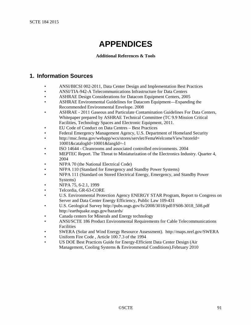
SCTE 184 2015
©SCTE 91
APPENDICES Additional References & Tools
1. Information Sources • ANSI/BICSI 002-2011, Data Center Design and Implementation Best Practices • ANSI/TIA-942-A Telecommunications Infrastructure for Data Centers • ASHRAE Design Considerations for Datacom Equipment Centers, 2005 • ASHRAE Environmental Guidelines for Datacom Equipment—Expanding the
Recommended Environmental Envelope. 2008 • ASHRAE - 2011 Gaseous and Particulate Contamination Guidelines For Data Centers,
Whitepaper prepared by ASHRAE Technical Committee (TC 9.9 Mission Critical Facilities, Technology Spaces and Electronic Equipment, 2011.
• EU Code of Conduct on Data Centres – Best Practices • Federal Emergency Management Agency, U.S. Department of Homeland Security • http://msc.fema.gov/webapp/wcs/stores/servlet/FemaWelcomeView?storeId=
10001&catalogId=10001&langId=-1 • ISO 14644 - Cleanrooms and associated controlled environments. 2004 • MEPTEC Report. The Threat to Miniaturization of the Electronics Industry. Quarter 4,
2004 • NFPA 70 (the National Electrical Code) • NFPA 110 (Standard for Emergency and Standby Power Systems) • NFPA 111 (Standard on Stored Electrical Energy, Emergency, and Standby Power
Systems) • NFPA 75, 6-2.1, 1999 • Telcordia, GR-63-CORE • U.S. Environmental Protection Agency ENERGY STAR Program, Report to Congress on
Server and Data Center Energy Efficiency, Public Law 109-431 • U.S. Geological Survey http://pubs.usgs.gov/fs/2008/3018/pdf/FS08-3018_508.pdf
http://earthquake.usgs.gov/hazards/ • Canada centers for Minerals and Energy technology • ANSI/SCTE 186 Product Environmental Requirements for Cable Telecommunications
Facilities • SWERA (Solar and Wind Energy Resource Assessment). http://maps.nrel.gov/SWERA • Uniform Fire Code , Article 100.7.3 of the 1994 • US DOE Best Practices Guide for Energy-Efficient Data Center Design (Air
Management, Cooling Systems & Environmental Conditions).February 2010
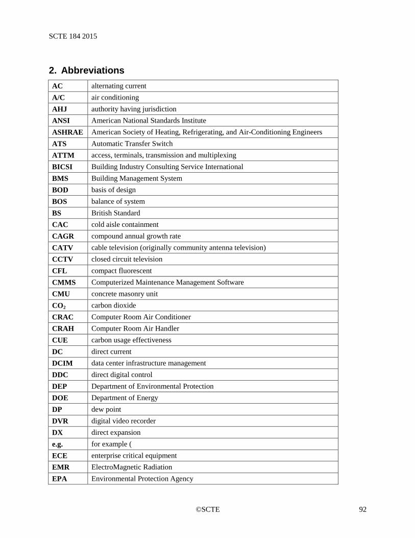
SCTE 184 2015
©SCTE 92
2. Abbreviations AC alternating current A/C air conditioning AHJ authority having jurisdiction ANSI American National Standards Institute ASHRAE American Society of Heating, Refrigerating, and Air-Conditioning Engineers ATS Automatic Transfer Switch ATTM access, terminals, transmission and multiplexing BICSI Building Industry Consulting Service International BMS Building Management System BOD basis of design BOS balance of system BS British Standard CAC cold aisle containment CAGR compound annual growth rate CATV cable television (originally community antenna television) CCTV closed circuit television CFL compact fluorescent CMMS Computerized Maintenance Management Software CMU concrete masonry unit CO2 carbon dioxide CRAC Computer Room Air Conditioner CRAH Computer Room Air Handler CUE carbon usage effectiveness DC direct current DCIM data center infrastructure management DDC direct digital control DEP Department of Environmental Protection DOE Department of Energy DP dew point DVR digital video recorder DX direct expansion e.g. for example ( ECE enterprise critical equipment EMR ElectroMagnetic Radiation EPA Environmental Protection Agency
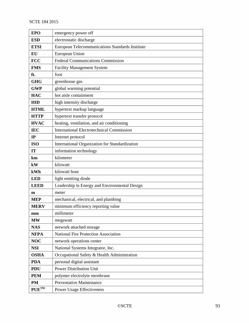
SCTE 184 2015
©SCTE 93
EPO emergency power off ESD electrostatic discharge ETSI European Telecommunications Standards Institute EU European Union FCC Federal Communications Commission FMS Facility Management System ft. foot GHG greenhouse gas GWP global warming potential HAC hot aisle containment HID high intensity discharge HTML hypertext markup language HTTP hypertext transfer protocol HVAC heating, ventilation, and air conditioning IEC International Electrotechnical Commission IP Internet protocol ISO International Organization for Standardization IT information technology km kilometer kW kilowatt kWh kilowatt hour LED light emitting diode LEED Leadership in Energy and Environmental Design m meter MEP mechanical, electrical, and plumbing MERV minimum efficiency reporting value mm millimeter MW megawatt NAS network attached storage NFPA National Fire Protection Association NOC network operations center NSI National Systems Integrator, Inc. OSHA Occupational Safety & Health Administration PDA personal digital assistant PDU Power Distribution Unit PEM polymer electrolyte membrane PM Preventative Maintenance PUETM Power Usage Effectiveness
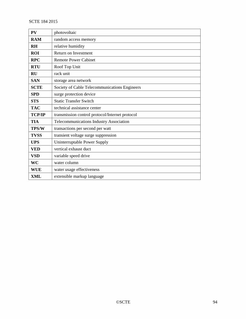
SCTE 184 2015
©SCTE 94
PV photovoltaic RAM random access memory RH relative humidity ROI Return on Investment RPC Remote Power Cabinet RTU Roof Top Unit RU rack unit SAN storage area network SCTE Society of Cable Telecommunications Engineers SPD surge protection device STS Static Transfer Switch TAC technical assistance center TCP/IP transmission control protocol/Internet protocol TIA Telecommunications Industry Association TPS/W transactions per second per watt TVSS transient voltage surge suppression UPS Uninterruptable Power Supply VED vertical exhaust duct VSD variable speed drive WC water column WUE water usage effectiveness XML extensible markup language