lennoxlennoxglobal.com/en/wp-content/uploads/2016/02/lennox_english_vrf... · consumer’s...
TRANSCRIPT


Trust, Innovation, Quality ... We Are
For over 100 years, Lennox® has established itself as a trusted company, distinguished
for being a pioneer in innovation and quality in all different areas of the Heating,
Ventilation and Air Conditioning (HVAC) industry. Our philosophy is to provide our
customers with products and services that include the latest technology, which
result in lower energy consumption, provide greater comfort, and meet the
consumer’s requirements.
Our Variable Refrigerant Flow (VRF) product line allows conditioning the space on
an area by area basis, offering the flexibility to select the components that best
suit your decor.
These features, as well as the individual control and low power consumption, make
these systems ideal for applications such as hotels, schools, shopping malls, offices,
medical centers, restaurants, apartments, homes, among others.
Our commitment is to work hand in hand with our partners to provide the technical
training and services needed to ensure their success. We maintain in our products
the tradition of quality and trust.
Lennox® ... Solutions at your fingertips
Why Lennox?

Technology
FAN BLADESOptimized for maximizing the volume of air and equipment efficiency. Designed to reduce noise and eliminate vibration.
MOTORHigh efficiency DC motor. Wide range of speeds that control the operation of the blades in a precise manner, increasing the overall efficiency of the equipment.
COILSubcooling control technology ensures optimal performance in cooling and heating cycles. Together with the hydrophilic fins, it maximizes heat transfer, performance, and efficiency.
INVERTER TYPE COMPRESSORSAll condensers are equipped with inverter compressors that adjust the system’s capacity in accordance with the thermal demand. With its precise capacity control, Inverter technology greatly reduces energy consumption.
COMMUNICATION TERMINALNon-polarity inputs eliminate the interconnection problems in com-plex constructions and improve the response speed between different control methods. They also reduce the installation and servicing costs.
SMART CONTROLMonitors the detailed operation of each system component. It has a LED display that helps control, startup and service the equipment.

Condensers
Mini VRF
• Compressors with high efficiency DC Inverter Technology
• Compressor startup at low frequency to lower the impact on the
power supply
• DC condenser motor
• Quiet operation
• Automatic addressing with the evaporators
• Electronic expansion valves
• Interference protection technology between condensers
and evaporators
• Maximum piping distance of up to 300 m (980 ft)
VRF
• Maximum combination of up to four (4) condensers reaching up to
50 TR
• Connection up to 80 evaporators
• Maximum piping length: 1000 m (3280 ft)
• “Y” branch connectors for refrigerant distribution
• Two (2) oil separation control stages
• Intelligent control of pressure and temperature
• Multiple electronic expansion valves for precise refrigerant control
• Compressor startup at low frequency to lower the impact on the
power supply
• Automatic addressing with the evaporators
• Static air discharge pressure of up to 82 Pa (0.33 in. W.C.)
• One (1) compressor in 75, 96, 120 MBtu units, and two (2)
compressors in 132 and 150 MBtu units
• Ambient temperature operating range between -5˚C and 52˚C
(23˚F - 12˚F) in cooling cycle
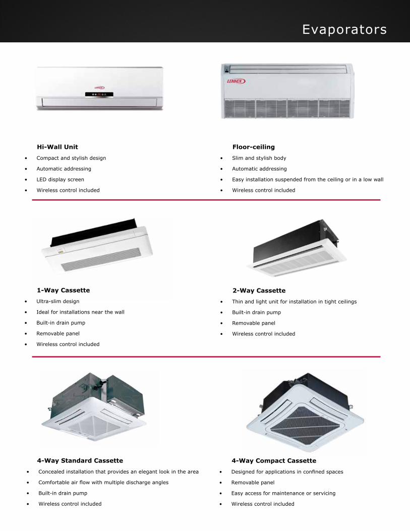
Evaporators
Hi-Wall Unit
• Compact and stylish design
• Automatic addressing
• LED display screen
• Wireless control included
Floor-ceiling
• Slim and stylish body
• Automatic addressing
• Easy installation suspended from the ceiling or in a low wall
• Wireless control included
4-Way Standard Cassette
• Concealed installation that provides an elegant look in the area
• Comfortable air flow with multiple discharge angles
• Built-in drain pump
• Wireless control included
2-Way Cassette
• Thin and light unit for installation in tight ceilings
• Built-in drain pump
• Removable panel
• Wireless control included
1-Way Cassette
• Ultra-slim design
• Ideal for installations near the wall
• Built-in drain pump
• Removable panel
• Wireless control included
4-Way Compact Cassette
• Designed for applications in confined spaces
• Removable panel
• Easy access for maintenance or servicing
• Wireless control included

Evaporators
Low Static Fan Coil
• Drain pump included
• Versatile mounting of return air through the bottom or back sides
• Static pressure drop of up to 50 Pa
• Adjustable static pressure
• Wired control included
Slim Fan Coil
• Ultra-slim body with a height of only 200 mm
• Versatile mounting of return air through the bottom or back sides
• Static pressure drop of up to 15 Pa
• Wired control included
High Static Fan Coil
• Drain pump included
• Versatile mounting of return air through the bottom or back sides
• Static pressure drop of up to 150 Pa
• Adjustable static pressure
• Wired control included

Controls
Remote Control
Individual multifunctional wireless control provides maximum versatility and innovation for adjusting the comfort
level on an area by area basis.
• Modes: Auto, Cooling, Heating, Dehumidification, Fan
• Shows the ambient temperature and the room temperature
• Adjusts addressing of indoor units
• Includes receiving unit for Fan-Coil type equipment
Wired Control
Convenience and versatility are the key factors in these controllers. It is the best choice for commercial
applications where its use is frequent.
• Illuminated display
• Master and slave configuration for the condensers
• Simultaneous control of several evaporators
• Review of system parameters: IDs, IP addresses, fault or service codes, etc.
Central Control
Optimum operation of the system from a single device that allows overall control of evaporators and condensers.
This option eliminates the need for the multiple use of several controls in a same project.
• Stylish look
• Up to 255 evaporators or 16 systems can be controlled from the same device
• Setting of hours of operation
• Access to system’s operating parameters
Modbus
Optimal control for remote access from a web page or for interfacing with an Automated Building Management
(BMS) system.
• One (1) Modbus control handles up to 16 systems with a total of 128 evaporators
• Two (2) Modbus controls handle up to 16 systems with a total of 255 evaporators
BACnet
Versatile system with multiple functionality for the automated control of the project.
• It connects to the BMS with which the following can be controlled:
-Lights
-Fire alarm
-Ventilation system
-Elevators
-Electricity and more

Piping Distance
MINI VRF Condensers
Model VEP042N432U VEP048N432U VEP060N432U
Voltage 220-240V / 1-Ph / 50Hz --- 208-230V / 1-Ph / 60 Hz
Cooling Btu/h 41,285 47,768 54,592
Heating Btu/h 47,768 56,298 63,122
EER/COP (W/W) 3.97 / 4.28 3.52 / 4.14 3.3 / 3.96
MOP/MCA (A) 32 / 28.1 32 / 31.8 40 / 33.6
No. Fans 2 2 2
Compressor Type INVERTER
W/D/H mm (in) 900 / 340 / 1345 (35.5 / 13.25 / 53)
Dia. Liq/Gas (in) 3/8 - 5/8 3/8 - 3/4
Pipe Connection Flared
Max. Evaporators 7 8 9
( (
Total allowable:
Maximum distance from condensers to farthest evaporator:
Maximum distance from the first connector to the farthest evaporator:
Maximum vertical distance from condensers to evaporators
(condensers located above):
Maximum vertical distance from condensers to evaporators
(condensers located below):
Maximum vertical distance between evaporators:
Distances from first connector to farthest evaporator -
Distance from first connector to first evaporator:
1000 m (3280 ft)
165 m (541 ft)
40 m (131 ft)
40 m (131 ft)
50 m (164 ft)
90 m (295 ft)
30 m (98 ft)
+
+
+
+
+
+
+
+
+
+
+
+
+
+
+
+
+
-
+ + =
=
=
=
=
=
=
A
A
D
D
B
B
D
B
B
F
F
D
D
F
C
D
G
G
F
F
D
F
C
E
G
F G

Model Combination TR
VEP171N432 (K,G) 75 + 96 14.25
VEP192N432 (K,G) 96 + 96 16
VEP216N432 (K,G) 96 + 120 18
VEP228N432 (K,G) 96 + 132 19
VEP246N432 (K,G) 96 + 150 20.5
VEP270N432 (K,G) 120 + 150 22.5
VEP282N432 (K,G) 132 + 150 23.5
VEP300N432 (K,G) 150 + 150 25
Condenser Specifications
Combinations
Model TR
VEP075N432 (K,G) 6.25
VEP096N432 (K,G) 8
VEP120N432 (K,G) 10
VEP132N432 (K,G) 11
VEP150N432 (K,G) 12.5
Model Combination TR
VEP324N432 (K,G) 96 + 96 + 132 27
VEP342N432 (K,G) 96 + 96 + 150 28.5
VEP366N432 (K,G) 96 + 120 + 150 30.5
VEP378N432 (K,G) 96 + 132 + 150 31.5
VEP396N432 (K,G) 96 + 150 + 150 33
VEP420N432 (K,G) 120 + 150 + 150 35
VEP432N432 (K,G) 132 + 150 + 150 36
VEP450N432 (K,G) 150 + 150 +150 37.5
Model Combination TR
VEP474N432 (K,G) 96 + 96 + 132 + 150 39.5
VEP492N432 (K,G) 96 + 96 + 150 + 150 41
VEP516N432 (K,G) 96 + 120 + 150 + 150 43
VEP528N432 (K,G) 96 + 132 + 150 + 150 44
VEP546N432 (K,G) 96 + 150 + 150 + 150 45.5
VEP570N432 (K,G) 120 + 150 + 150 + 150 47.5
VEP582N432 (K,G) 132 + 150 + 150 + 150 48.5
VEP600N432 (K,G) 150 + 150 + 150 + 150 50
2 Condensers
4 Condensers
1 Condenser
3 Condensers
VRF Condensers Model VEP075N432 (K,G) VEP096N432 (K,G) VEP120N432 (K,G) VEP132N432 (K,G) VEP150N432 (K,G)
Voltage 220-240V / 3-Ph / 50 Hz --- 208-230V / 3-Ph / 60 Hz --- 440-460V / 3-Ph / 60 Hz
Cooling Btu/h 76,430 95,540 114,302 136,480 153,540
Heating Btu/h 85,300 107,480 127,950 153,540 170,600
Compressor Type INVERTER
W/D/H mm (in) 930/765/1605 (36.5/30.2/63.2) 1340/765/1605 (52.75/30.2/63.2)
Dia. Liq/Gas (in) 1/4 - 3/4 1/4 - 1 1/2 - 1 1/2 - 1 1/8

Evaporator Specifications
4-Way Standard Cassette
Model VE4C012N432U VE4C019N432U VE4C024N432U VE4C038N432U VE4C048N432U
Voltage 220-240V / 1-Ph / 50Hz --- 208-230V / 1-Ph / 60Hz
Cooling Btu/h 12,283 19,107 24,225 38,214 47,768
Heating Btu/h 13,648 21,496 27,296 42,650 54,592
MOP (A) 6 6 6 6 6
No. Fans 1 1 1 1 1
Air Flow (CFM) 440/383/325 590/530/440 695/559/550 1000/824/650 1095/880/677
W/D/H (mm) 840/840/190 840/840/240 840/840/320
W/D/H (in) 33/33/7.5 33/33/9.5 33/33/12.6
Dia. Liq/Gas (in) 1/4 - 1/2 3/8 - 5/8
Drain Diameter (in) 1 1 1 1 1
Pipe Connection Flared
Model VEHW012N432P VEHW019N432P VEHW024N432P
Voltage 208-230V / 1-Ph / 60Hz
Cooling Btu/h 12,283 19,107 24,225
Heating Btu/h 13,648 21,496 25,590
MOP (A) 6 6 6
No. Fans 1 1 1
Air Flow (CFM) 371/324/282 441/353/294 441/353/294
W/D/H (mm) 940/200/298 1008/221/319 1008/221/319
W/D/H (in) 37/7.8/11.7 39.6/8.7/12.5 39.6/8.7/12.5
Dia. Liq/Gas (in) 1/4 - 1/2 3/8 - 5/8
Drain Diameter (in) 1 1 1
Pipe Connection Flared
VEUM012N432U VEUM024N432U VEUM038N432U
220-240V / 1-Ph / 50Hz --- 208-230V / 1-Ph / 60Hz
12,280 24,230 38,210
13,650 27,300 42,650
6 6 6
4 3 4
380/341/294 825/677/590 1175/1059/853
1220/700/225 1420/700/245 1700/700/245
48/27.5/8.8 56/27.5/9.6 67/27.5/9.6
1/4 - 1/2 3/8 - 5/8
3/4 3/4 3/4
Flared
Floor-CeilingHi-Wall Unit
2-Way Cassette1-Way Cassette
Model VE1C012N432U VE1C015N432U VE2C012N432U VE2C015N432U
Voltage 220-240V / 1-Ph / 50Hz --- 208-230V / 1-Ph / 60Hz 220-240V / 1-Ph / 50Hz --- 208-230V / 1-Ph / 60Hz
Cooling Btu/h 12,283 15,354 12,283 15,354Heating Btu/h 13,648 17,060 13,648 17,060MOP (A) 6 6 6 6
No. Fans 1 1 3 3
Air Flow (CFM) 355/295/265 490/355/295 490/355/312 490/355/312
W/D/H (mm) 987/385/178 1200/520/340
W/D/H (in) 39/15.1/7 47.2/20.4/13.4
Dia. Liq/Gas (in) 1/4 - 1/2 1/4 - 3/8
Drain Diameter (in) 1 1 1 1
Pipe Connection Flared Flared

Evaporator Specifications
Model VELD009N432U VELD012N432U VELD018N432U VELD024N432U
Voltage 220-240V / 1-Ph / 50Hz --- 208-230V / 1-Ph / 60Hz
Cooling Btu/h 9,544 12,283 17,060 24,225
Heating Btu/h 10,918 13,648 19,107 27,296
MOP (A) 6 6 6 6
No. Fans 2 2 3 2
Air Flow (CFM) 265/206/147 325/265/206 410/355/265 500/471/353
ESP (Pa) 0 ~ 30 0 ~ 30 0 ~ 50
W/D/H (mm) 700/615/200 900/615/200 1200/655/260
W/D/H (in) 27.5/24.3/7.8 35.4/24.2/7.8 47.2/25.7/10.2
Dia. Liq/Gas (in) 1/4 - 3/8 1/4 - 1/2 3/8 - 5/8
Drian Diameter (in) 1 1 1 1
Pipe Connection Flared
Low Static Fan Coil
Slim Fan Coil4-Way Compact Cassette
Model VECC012N432U VECC017N432U VESD012N432U VESD019N432U VESD024N432U
Voltage 220-240V / 1-Ph / 50Hz --- 208-230V / 1-Ph / 60Hz 220-240V / 1-Ph / 50Hz --- 208-230V / 1-Ph / 60Hz
Cooling Btu/h 12,280 17,060 12,283 19,107 24,566
Heating Btu/h 13,650 19,110 13,648 21,496 27,296
MOP (A) 6 6 6 6 6
No. Fans 1 1 2 3 4
Air Flow (CFM) 410/355/283 410/355/283 324/265/200 500/412/359 647/471/377
ESP (Pa) - - - 0 ~ 15
W/D/H (mm) 596/596/240 710/450/200 1010/450/200 1310/450/200
W/D/H (in) 23.5/23.5/9.5 28/17.7/7.8 39.75/17.7/7.8 51.5/17.7/7.8
Dia. Liq/Gas (in) 1/4 - 1/2 1/4 - 1/2 3/8 - 5/8
Drain Diameter (in) 1 1 - - -Pipe Connection Flared Flared
High Static Fan Coil
Model VEHD019N432U VEHD024N432U VEHD034N432U VEHD048N432U VEHD055N432U VEGD076N432U VEGD095N432U
Voltage 220-240 / 1-Ph / 50Hz --- 208-230V / 1-Ph / 60Hz
Cooling Btu/h 19,107 24,225 34,120 47,768 54,590 76,430 95,540
Heating Btu/h 21,496 27,296 38,210 54,592 58,000 85,300 105,770
MOP (A) 6 6 6 6 6 10 16
No. Fans 2 2 2 2 2 2 2
Air Flow (CMF) 590/471/355 650/530/410 1000/853/650 1175/912/706 1824 2355 2590
ESP (Pa) 0-100 0-150 0-200
W/D/H (mm) 1271/558/268 1229/775/290 1340/750/350 1493/791/385 1686/870/450
W/D/H (in) 50/22/10.5 48.4/30.5/11.4 52.75/29.5/13.75 58.4/31.1/15.2 66.4/34.2/17.7
Dia. Liq/Gas (in) 5/8 - 3/8 3/8 - 3/4 3/8 -7/8
Drian Diameter (in) 1 1 1 1 1 1 1
Pipe Connection Flared Brazed

Residential and Commercial Applications
© 2015 Lennox Industries Inc. For a complete list of the registered and common law trademarks owned by Lennox Industries Inc., please visit www.lennox.comNMGVSE01-2015
Contact us at +1-305-718-2901lennoxglobalhvac@lennoxintl.comwww.lennoxglobal.com
Homes: Allows low noise levels and low operating cost.
Hospitality: Provides individual control per room or centralized control per floor or per area for better comfort and energy savings.
Shopping Malls: Prevents sudden temperature changes.
Apartments: Saves space and provides maximum comfort.
Education: Provides a quiet and effective environment.
Offices: Provides temperature control for each office and common areas.
Restaurants: Provides maximum comfort during hours of operation.