pt-2000 series ac/dc current probe · pt-2000 series ac/dc current probe pt-2710 pt-2720 pt-2740...
TRANSCRIPT

PT-2000series AC/DCcurrentprobe
PT-2710PT-2710PT-2710PT-2710
PT-2720PT-2720PT-2720PT-2720
PT-2740PT-2740PT-2740PT-2740
PT-2770PT-2770PT-2770PT-2770
INSTRUCTIONINSTRUCTIONINSTRUCTIONINSTRUCTION MANUALMANUALMANUALMANUAL

GeneralGeneralGeneralGeneral SafetySafetySafetySafety Instructions:Instructions:Instructions:Instructions:Read the following safety instructions to avoid injury and prevent damageto this product or any products connected to it. Use this product only asspecified.
Only qualified personnel should perform service procedures.
ToToToTo AvoidAvoidAvoidAvoid FireFireFireFire orororor PersonalPersonalPersonalPersonal InjuryInjuryInjuryInjury
ConnectConnectConnectConnect andandandand DisconnectDisconnectDisconnectDisconnect ProperlyProperlyProperlyProperly.... Connect the probe output to themeasurement instrument before connecting the probe to the circuit undertest. Disconnect the probe input and the probe ground from the circuitunder test before disconnecting the probe from the measurementinstrument.
ObserveObserveObserveObserve AllAllAllAll TerminalTerminalTerminalTerminal RatingsRatingsRatingsRatings.... To avoid fire or shock hazard, observeall rating and markings on the product. Consult the instruction manual forfurther ratings information before making connections to the product.
ReplaceReplaceReplaceReplace BatteriesBatteriesBatteriesBatteries ProperlyProperlyProperlyProperly.... Replace batteries only with the propertype and rating specified.
DoDoDoDo NotNotNotNot OperateOperateOperateOperate WithoutWithoutWithoutWithout CoversCoversCoversCovers.... Do not operate this product withoutthe covers or panels.
AvoidAvoidAvoidAvoid ExposedExposedExposedExposed CircuitryCircuitryCircuitryCircuitry.... Do not touch exposed connections andcomponents when power is present.
DoDoDoDo NotNotNotNot OperateOperateOperateOperate WithWithWithWith SuspectedSuspectedSuspectedSuspected FailuresFailuresFailuresFailures.... If you suspect there isdamage to this product, have it inspected by qualified service personnel.
DoDoDoDo NotNotNotNot OperateOperateOperateOperate inininin WetWetWetWet////DampDampDampDamp ConditionsConditionsConditionsConditions....
DoDoDoDo NotNotNotNot OperateOperateOperateOperate inininin anananan ExplosiveExplosiveExplosiveExplosive AtmosphereAtmosphereAtmosphereAtmosphere....
KeepKeepKeepKeep ProductProductProductProduct SurfacesSurfacesSurfacesSurfaces CleanCleanCleanClean andandandand DryDryDryDry....

SafetySafetySafetySafety TermsTermsTermsTerms andandandand Symbols:Symbols:Symbols:Symbols:TermsTermsTermsTerms inininin ThisThisThisThis Manual.Manual.Manual.Manual. These terms may appear in this manual:
WARNING.WARNING.WARNING.WARNING.Warning statements identify conditions or practicesthat could result in injury or loss of life.
CAUTION.CAUTION.CAUTION.CAUTION. Caution statements identify conditions or practicesthat could result in damage to this product or other property.
TermsTermsTermsTerms onononon thethethethe Product.Product.Product.Product. These terms may appear on the product:
DANGERDANGERDANGERDANGER indicates an injury hazard immediately accessible as you readthe marking.
WARNINGWARNINGWARNINGWARNING indicates an injury hazard not immediately accessible as youread the marking.
CAUTIONCAUTIONCAUTIONCAUTION indicates a hazard to property including the product.
SymbolsSymbolsSymbolsSymbols onononon thethethethe Product.Product.Product.Product. These symbols may appear on the product:
Attention refer to operation Instructions.
This instrument has double insulation.
GettingGettingGettingGetting Started:Started:Started:Started:
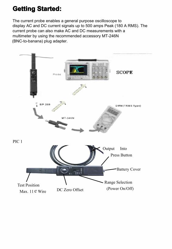
The current probe enables a general purpose oscilloscope todisplay AC and DC current signals up to 500 amps Peak (180 A RMS). Thecurrent probe can also make AC and DC measurements with amultimeter by using the recommended accessory MT-246N(BNC-to-banana) plug adapter.
PIC 1
Output IntoPress Button
Battery Cover
Range Selection(Power On/Off)DC Zero Offset
Test PositionMax. 11¢Wire
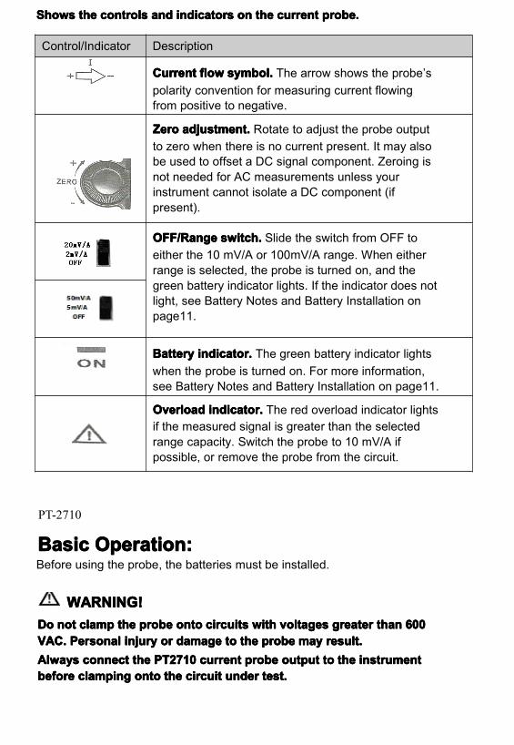
SSSShowshowshowshows thethethethe controlscontrolscontrolscontrols andandandand indicatorsindicatorsindicatorsindicators onononon thethethethe currentcurrentcurrentcurrent probe.probe.probe.probe.
PT-2710
BasicBasicBasicBasic Operation:Operation:Operation:Operation:Before using the probe, the batteries must be installed.
WARNING!WARNING!WARNING!WARNING!DoDoDoDo notnotnotnot clampclampclampclamp thethethethe probeprobeprobeprobe ontoontoontoonto circuitscircuitscircuitscircuits withwithwithwith voltagesvoltagesvoltagesvoltages greatergreatergreatergreater thanthanthanthan 600600600600VAC.VAC.VAC.VAC. PersonalPersonalPersonalPersonal injuryinjuryinjuryinjury orororor damagedamagedamagedamage totototo thethethethe probeprobeprobeprobe maymaymaymay result.result.result.result.AlwaysAlwaysAlwaysAlways connectconnectconnectconnect thethethethe PPPPT2710T2710T2710T2710 currentcurrentcurrentcurrent probeprobeprobeprobe outputoutputoutputoutput totototo thethethethe instrumentinstrumentinstrumentinstrumentbeforebeforebeforebefore clampingclampingclampingclamping ontoontoontoonto thethethethe circuitcircuitcircuitcircuit underunderunderunder test.test.test.test.
Control/Indicator Description
CurrentCurrentCurrentCurrent flowflowflowflow symbol.symbol.symbol.symbol. The arrow shows the probe’spolarity convention for measuring current flowingfrom positive to negative.
ZeroZeroZeroZero adjustment.adjustment.adjustment.adjustment. Rotate to adjust the probe outputto zero when there is no current present. It may alsobe used to offset a DC signal component. Zeroing isnot needed for AC measurements unless yourinstrument cannot isolate a DC component (ifpresent).
OFF/RangeOFF/RangeOFF/RangeOFF/Range switch.switch.switch.switch. Slide the switch from OFF toeither the 10 mV/A or 100mV/A range. When eitherrange is selected, the probe is turned on, and thegreen battery indicator lights. If the indicator does notlight, see Battery Notes and Battery Installation onpage11.
BatteryBatteryBatteryBattery indicator.indicator.indicator.indicator. The green battery indicator lightswhen the probe is turned on. For more information,see Battery Notes and Battery Installation on page11.
OverloadOverloadOverloadOverload indicator.indicator.indicator.indicator. The red overload indicator lightsif the measured signal is greater than the selectedrange capacity. Switch the probe to 10 mV/A ifpossible, or remove the probe from the circuit.
1. First connect the current probe BNC connector to BP-250 (double BNCconnection cable) then connect to oscilloscope input. Start by setting theoscilloscope voltage input channel to DC volts, and the voltage sensitivityscale to 5m V/div.
2. Move the OFF/ Range switch to the 5 mV/A or 50 mV/A position toturn on the probe.(※The PT-2710 current probe has a green LED power/battery indicator. Ifthe LED does not light, replace the battery or use specified poweradaptor.)
3. Use the ZERO adjustment to zero or offset the probe output detection ofresidual magnetic DC charges.
4. Connect the probe to the circuit by opening the jaws and clampingaround the conductor. See Figure 2.NOTE.NOTE.NOTE.NOTE. ClampingClampingClampingClamping aroundaroundaroundaround bothbothbothboth thethethethe ““““hothothothot”””” andandandand neutralneutralneutralneutral wireswireswireswires maymaymaymay givegivegivegiveyouyouyouyou aaaa zerozerozerozero reading.reading.reading.reading.(Remember(Remember(Remember(Remember totototo unclampunclampunclampunclamp thethethethe probeprobeprobeprobe fromfromfromfrom thethethethe conductorconductorconductorconductor beforebeforebeforebeforedisconnectingdisconnectingdisconnectingdisconnecting itititit fromfromfromfrom youryouryouryour metermetermetermeter orororor instrument).instrument).instrument).instrument).
5. Adjust the probe channel and oscilloscope’s time base as necessary toget a clear and stable view of the signal. Set the oscilloscope input to DCvolts to see both the AC and DC currents; set the channel to AC to seethe AC current only.The current drawn by different devices look much different than that ofothers. While the RMS current can only be used in low frequency current,the momentary peaks may be quite high. Figure 3 shows the differencebetween the line current drawn by a resistive load and a motor controller.
Congratulations on your purchase of the PT-2710, a multifunctional currentprobe. When connecting to a digital meter, use the recommendedMT-246N (BNC-to-banana adapter). Connect the black lead to the meterCOM (black letters on the meter), and the red lead to the VΩ input (redletters on the meter).
To measure only AC current, set the meter to measure AC volts.
To measure DC current, set the meter to measure DC volts. Note thecurrent convention arrow on the probe to get the proper polarity reading.
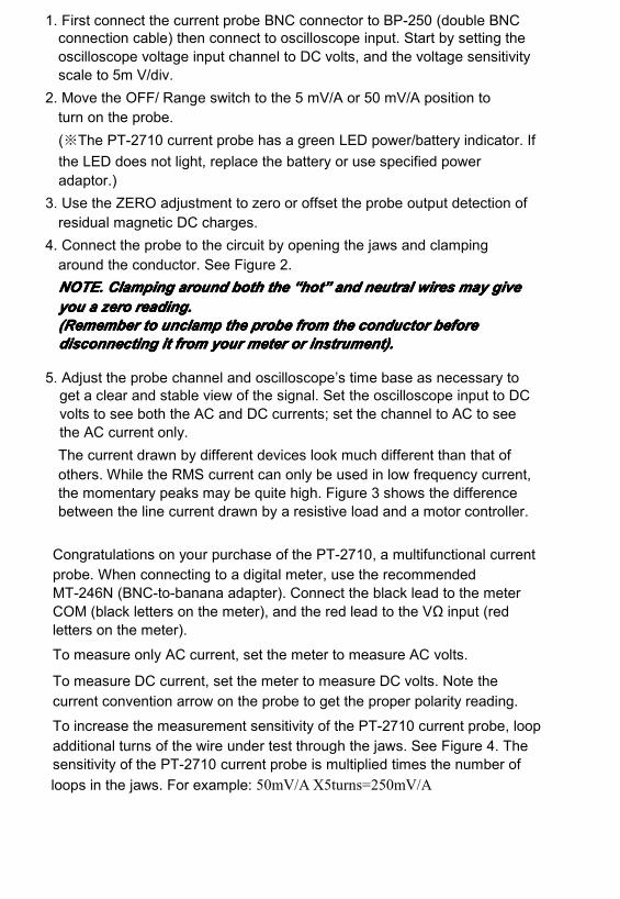
To increase the measurement sensitivity of the PT-2710 current probe, loopadditional turns of the wire under test through the jaws. See Figure 4. Thesensitivity of the PT-2710 current probe is multiplied times the number ofloops in the jaws. For example: 50mV/A X5turns=250mV/A
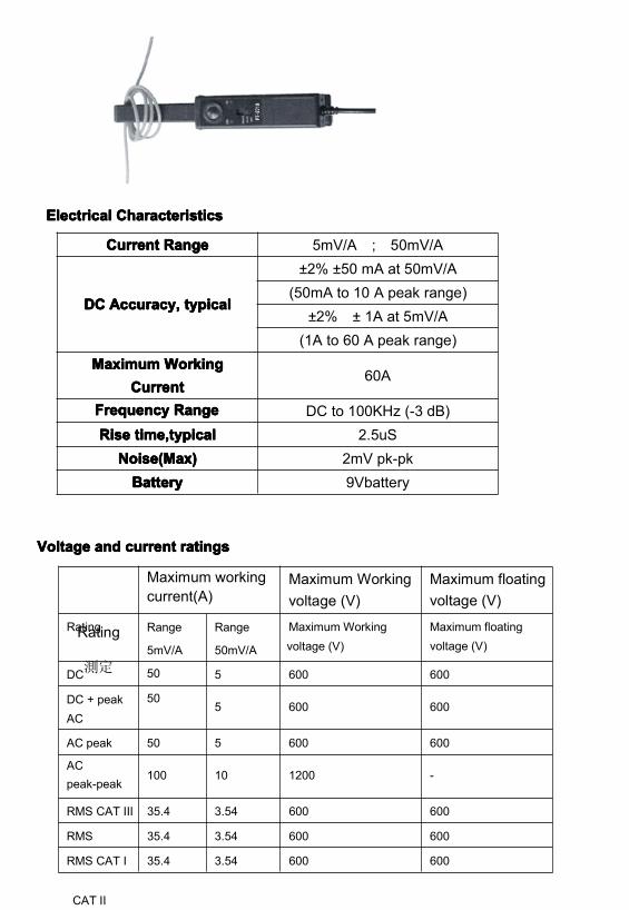
ElectricalElectricalElectricalElectrical CharacteristicsCharacteristicsCharacteristicsCharacteristics
VoltageVoltageVoltageVoltage andandandand currentcurrentcurrentcurrent ratingsratingsratingsratings
CurrentCurrentCurrentCurrent RangeRangeRangeRange 5mV/A ; 50mV/A
DCDCDCDC Accuracy,Accuracy,Accuracy,Accuracy, typicatypicatypicatypicallll
±2% ±50 mA at 50mV/A(50mA to 10 A peak range)
±2% ± 1A at 5mV/A(1A to 60 A peak range)
MaximumMaximumMaximumMaximum WorkingWorkingWorkingWorkingCurrentCurrentCurrentCurrent
60A
FrequencyFrequencyFrequencyFrequency RangeRangeRangeRange DC to 100KHz (-3 dB)RiseRiseRiseRise time,typicaltime,typicaltime,typicaltime,typical 2.5uS
Noise(Max)Noise(Max)Noise(Max)Noise(Max) 2mV pk-pkBatteryBatteryBatteryBattery 9Vbattery
Rating
測定
Maximum workingcurrent(A)
Maximum Workingvoltage (V)
Maximum floatingvoltage (V)
Rating Range
5mV/A
Range
50mV/A
Maximum Workingvoltage (V)
Maximum floatingvoltage (V)
DC 50 5 600 600
DC + peakAC
505 600 600
AC peak 50 5 600 600
ACpeak-peak
100 10 1200 -
RMS CAT III 35.4 3.54 600 600
RMS
CAT II
35.4 3.54 600 600
RMS CAT I 35.4 3.54 600 600
PT-2720
BasicBasicBasicBasic Operation:Operation:Operation:Operation:Before using the probe, the batteries must be installed.
WARNING!WARNING!WARNING!WARNING!DoDoDoDo notnotnotnot clampclampclampclamp thethethethe probeprobeprobeprobe ontoontoontoonto circuitscircuitscircuitscircuits withwithwithwith voltagesvoltagesvoltagesvoltages greatergreatergreatergreater thanthanthanthan 600600600600VAC.VAC.VAC.VAC. PersonalPersonalPersonalPersonal injuryinjuryinjuryinjury orororor damagedamagedamagedamage totototo thethethethe probeprobeprobeprobe maymaymaymay result.result.result.result.AlwaysAlwaysAlwaysAlways connectconnectconnectconnect thethethethe PPPPT2720T2720T2720T2720 currentcurrentcurrentcurrent probeprobeprobeprobe outputoutputoutputoutput totototo thethethethe instrumentinstrumentinstrumentinstrumentbeforebeforebeforebefore clampingclampingclampingclamping ontoontoontoonto thethethethe circuitcircuitcircuitcircuit underunderunderunder test.test.test.test.
1. First connect the current probe BNC connector to BP-250 (double BNCconnection cable) then connect to oscilloscope input. Start by setting theoscilloscope voltage input channel to DC volts, and the voltage sensitivityscale to 2m V/div.
2. Move the OFF/ Range switch to the 2 mV/A or 20 mV/A position toturn on the probe.(※The PT-2710 current probe has a green LED power/battery indicator. Ifthe LED does not light, replace the battery or use specified poweradaptor.)
3. Use the ZERO adjustment to zero or offset the probe output detection ofresidual magnetic DC charges.
4. Connect the probe to the circuit by opening the jaws and clampingaround the conductor. See Figure 2.NOTE.NOTE.NOTE.NOTE. ClampingClampingClampingClamping aroundaroundaroundaround bothbothbothboth thethethethe ““““hothothothot”””” andandandand neutralneutralneutralneutral wireswireswireswires maymaymaymay givegivegivegiveyouyouyouyou aaaa zerozerozerozero reading.reading.reading.reading.(Remember(Remember(Remember(Remember totototo unclampunclampunclampunclamp thethethethe probeprobeprobeprobe fromfromfromfrom thethethethe conductorconductorconductorconductor beforebeforebeforebeforedisconnectingdisconnectingdisconnectingdisconnecting itititit fromfromfromfrom youryouryouryour metermetermetermeter orororor instrument).instrument).instrument).instrument).
5. Adjust the probe channel and oscilloscope’s time base as necessary toget a clear and stable view of the signal. Set the oscilloscope input to DCvolts to see both the AC and DC currents; set the channel to AC to seethe AC current only.The current drawn by different devices look much different than that ofothers. While the RMS current can only be used in low frequency current,the momentary peaks may be quite high. Figure 3 shows the differencebetween the line current drawn by a resistive load and a motor controller.
Congratulations on your purchase of the PT-2720, a multifunctional currentprobe. When connecting to a digital meter, use the recommendedMT-246N (BNC-to-banana adapter). Connect the black lead to the meterCOM (black letters on the meter), and the red lead to the VΩ input (redletters on the meter).
To measure only AC current, set the meter to measure AC volts.
To measure DC current, set the meter to measure DC volts. Note thecurrent convention arrow on the probe to get the proper polarity reading.
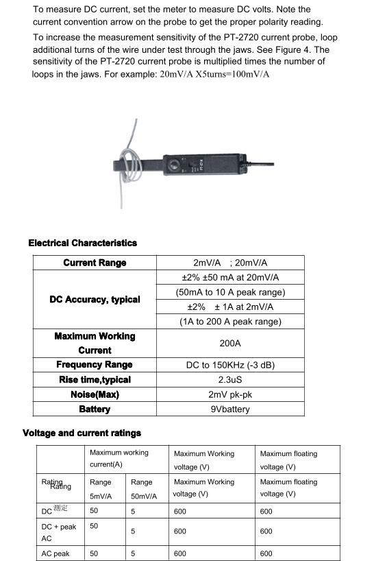
To increase the measurement sensitivity of the PT-2720 current probe, loopadditional turns of the wire under test through the jaws. See Figure 4. Thesensitivity of the PT-2720 current probe is multiplied times the number ofloops in the jaws. For example: 20mV/A X5turns=100mV/A
ElectricalElectricalElectricalElectrical CharacteristicsCharacteristicsCharacteristicsCharacteristics
VoltageVoltageVoltageVoltage andandandand currentcurrentcurrentcurrent ratingsratingsratingsratings
CurrentCurrentCurrentCurrent RangeRangeRangeRange 2mV/A ; 20mV/A
DCDCDCDC Accuracy,Accuracy,Accuracy,Accuracy, typicatypicatypicatypicallll
±2% ±50 mA at 20mV/A(50mA to 10 A peak range)
±2% ± 1A at 2mV/A(1A to 200 A peak range)
MaximumMaximumMaximumMaximum WorkingWorkingWorkingWorkingCurrentCurrentCurrentCurrent
200A
FrequencyFrequencyFrequencyFrequency RangeRangeRangeRange DC to 150KHz (-3 dB)RiseRiseRiseRise time,typicaltime,typicaltime,typicaltime,typical 2.3uS
Noise(Max)Noise(Max)Noise(Max)Noise(Max) 2mV pk-pkBatteryBatteryBatteryBattery 9Vbattery
Rating
測定
Maximum workingcurrent(A)
Maximum Working
voltage (V)
Maximum floating
voltage (V)
Rating Range
5mV/A
Range
50mV/A
Maximum Workingvoltage (V)
Maximum floatingvoltage (V)
DC 50 5 600 600
DC + peakAC
505 600 600
AC peak 50 5 600 600

PT-2740
BasicBasicBasicBasic Operation:Operation:Operation:Operation:Before using the probe, the batteries must be installed.
WARNING!WARNING!WARNING!WARNING!DoDoDoDo notnotnotnot clampclampclampclamp thethethethe probeprobeprobeprobe ontoontoontoonto circuitscircuitscircuitscircuits withwithwithwith voltagesvoltagesvoltagesvoltages greatergreatergreatergreater thanthanthanthan 600600600600VAC.VAC.VAC.VAC. PersonalPersonalPersonalPersonal injuryinjuryinjuryinjury orororor damagedamagedamagedamage totototo thethethethe probeprobeprobeprobe maymaymaymay result.result.result.result.AlwaysAlwaysAlwaysAlways connectconnectconnectconnect thethethethe PPPPT2740T2740T2740T2740 currentcurrentcurrentcurrent probeprobeprobeprobe outputoutputoutputoutput totototo thethethethe instrumentinstrumentinstrumentinstrumentbeforebeforebeforebefore clampingclampingclampingclamping ontoontoontoonto thethethethe circuitcircuitcircuitcircuit underunderunderunder test.test.test.test.
1. First connect the current probe BNC connector to BP-250 (double BNCconnection cable) then connect to oscilloscope input. Start by setting theoscilloscope voltage input channel to DC volts, and the voltage sensitivityscale to 2m V/div.
2. Move the OFF/ Range switch to the 2 mV/A or 20 mV/A position toturn on the probe.(※The PT-2740 current probe has a green LED power/battery indicator. Ifthe LED does not light, replace the battery or use specified poweradaptor.)
3. Use the ZERO adjustment to zero or offset the probe output detection ofresidual magnetic DC charges.
4. Connect the probe to the circuit by opening the jaws and clampingaround the conductor. See Figure 2.NOTE.NOTE.NOTE.NOTE. ClampingClampingClampingClamping aroundaroundaroundaround bothbothbothboth thethethethe ““““hothothothot”””” andandandand neutralneutralneutralneutral wireswireswireswires maymaymaymay givegivegivegiveyouyouyouyou aaaa zerozerozerozero reading.reading.reading.reading.(Remember(Remember(Remember(Remember totototo unclampunclampunclampunclamp thethethethe probeprobeprobeprobe fromfromfromfrom thethethethe conductorconductorconductorconductor beforebeforebeforebeforedisconnectingdisconnectingdisconnectingdisconnecting itititit fromfromfromfrom youryouryouryour metermetermetermeter orororor instrument).instrument).instrument).instrument).
5. Adjust the probe channel and oscilloscope’s time base as necessary toget a clear and stable view of the signal. Set the oscilloscope input to DCvolts to see both the AC and DC currents; set the channel to AC to seethe AC current only.The current drawn by different devices look much different than that ofothers. While the RMS current can only be used in low frequency current,the momentary peaks may be quite high. Figure 3 shows the differencebetween the line current drawn by a resistive load and a motor controller.
ACpeak-peak
100 10 1200 -
RMS CAT III 35.4 3.54 600 600
RMS
CAT II
35.4 3.54 600 600
RMS CAT I 35.4 3.54 600 600
Congratulations on your purchase of the PT-2740, a multifunctional currentprobe. When connecting to a digital meter, use the recommendedMT-246N (BNC-to-banana adapter). Connect the black lead to the meterCOM (black letters on the meter), and the red lead to the VΩ input (redletters on the meter).
To measure only AC current, set the meter to measure AC volts.
To measure DC current, set the meter to measure DC volts. Note thecurrent convention arrow on the probe to get the proper polarity reading.
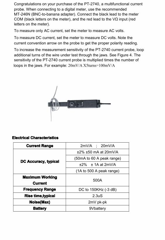
To increase the measurement sensitivity of the PT-2740 current probe, loopadditional turns of the wire under test through the jaws. See Figure 4. Thesensitivity of the PT-2740 current probe is multiplied times the number ofloops in the jaws. For example: 20mV/A X5turns=100mV/A
ElectricalElectricalElectricalElectrical CharacteristicsCharacteristicsCharacteristicsCharacteristics
CurrentCurrentCurrentCurrent RangeRangeRangeRange 2mV/A ; 20mV/A
DCDCDCDC Accuracy,Accuracy,Accuracy,Accuracy, typicatypicatypicatypicallll
±2% ±50 mA at 20mV/A(50mA to 60 A peak range)
±2% ± 1A at 2mV/A(1A to 500 A peak range)
MaximumMaximumMaximumMaximumWorkingWorkingWorkingWorkingCurrentCurrentCurrentCurrent
500A
FrequencyFrequencyFrequencyFrequency RangeRangeRangeRange DC to 150KHz (-3 dB)RiseRiseRiseRise time,typicaltime,typicaltime,typicaltime,typical 2.3uS
Noise(Max)Noise(Max)Noise(Max)Noise(Max) 2mV pk-pkBatteryBatteryBatteryBattery 9Vbattery

VoltageVoltageVoltageVoltage andandandand currentcurrentcurrentcurrent ratingsratingsratingsratings
PT-2770
BasicBasicBasicBasic Operation:Operation:Operation:Operation:Before using the probe, the batteries must be installed.
WARNING!WARNING!WARNING!WARNING!DoDoDoDo notnotnotnot clampclampclampclamp thethethethe probeprobeprobeprobe ontoontoontoonto circuitscircuitscircuitscircuits withwithwithwith voltagesvoltagesvoltagesvoltages greatergreatergreatergreater thanthanthanthan 600600600600VAC.VAC.VAC.VAC. PersonalPersonalPersonalPersonal injuryinjuryinjuryinjury orororor damagedamagedamagedamage totototo thethethethe probeprobeprobeprobe maymaymaymay result.result.result.result.AlwaysAlwaysAlwaysAlways connectconnectconnectconnect thethethethe PPPPT-2770T-2770T-2770T-2770 currentcurrentcurrentcurrent probeprobeprobeprobe outputoutputoutputoutput totototo thethethethe instrumentinstrumentinstrumentinstrumentbeforebeforebeforebefore clampingclampingclampingclamping ontoontoontoonto thethethethe circuitcircuitcircuitcircuit underunderunderunder test.test.test.test.
1. First connect the current probe BNC connector to BP-250 (double BNCconnection cable) then connect to oscilloscope input. Start by setting theoscilloscope voltage input channel to DC volts, and the voltage sensitivityscale to 2m V/div.
2. Move the OFF/ Range switch to the 2 mV/A or 20 mV/A position toturn on the probe.(※The PT-2770 current probe has a green LED power/battery indicator. Ifthe LED does not light, replace the battery or use specified poweradaptor.)
3. Use the ZERO adjustment to zero or offset the probe output detection ofresidual magnetic DC charges.
4. Connect the probe to the circuit by opening the jaws and clampingaround the conductor. See Figure 2.
Rating
測定
Maximum workingcurrent(A)
Maximum Working
voltage (V)
Maximum floating
voltage (V)
Rating Range
5mV/A
Range
50mV/A
Maximum Workingvoltage (V)
Maximum floatingvoltage (V)
DC 50 5 600 600
DC + peakAC
505 600 600
AC peak 50 5 600 600
ACpeak-peak
100 10 1200 -
RMS CAT
III
35.4 3.54 600 600
RMS
CAT II
35.4 3.54 600 600
RMS CAT I 35.4 3.54 600 600

NOTE.NOTE.NOTE.NOTE. ClampingClampingClampingClamping aroundaroundaroundaround bothbothbothboth thethethethe ““““hothothothot”””” andandandand neutralneutralneutralneutral wireswireswireswires maymaymaymay givegivegivegiveyouyouyouyou aaaa zerozerozerozero reading.reading.reading.reading.(Remember(Remember(Remember(Remember totototo unclampunclampunclampunclamp thethethethe probeprobeprobeprobe fromfromfromfrom thethethethe conductorconductorconductorconductor beforebeforebeforebeforedisconnectingdisconnectingdisconnectingdisconnecting itititit fromfromfromfrom youryouryouryour metermetermetermeter orororor instrument).instrument).instrument).instrument).
5. Adjust the probe channel and oscilloscope’s time base as necessary toget a clear and stable view of the signal. Set the oscilloscope input to DCvolts to see both the AC and DC currents; set the channel to AC to seethe AC current only.The current drawn by different devices look much different than that ofothers. While the RMS current can only be used in low frequency current,the momentary peaks may be quite high. Figure 3 shows the differencebetween the line current drawn by a resistive load and a motor controller.
Congratulations on your purchase of the PT-2770, a multifunctional currentprobe. When connecting to a digital meter, use the recommendedMT-246N (BNC-to-banana adapter). Connect the black lead to the meterCOM (black letters on the meter), and the red lead to the VΩ input (redletters on the meter).
To measure only AC current, set the meter to measure AC volts.
To measure DC current, set the meter to measure DC volts. Note thecurrent convention arrow on the probe to get the proper polarity reading.
To increase the measurement sensitivity of the PT-2770 current probe, loopadditional turns of the wire under test through the jaws. See Figure 4. Thesensitivity of the PT-2770 current probe is multiplied times the number ofloops in the jaws. For example: 20mV/A X5turns=100mV/A
ElectricalElectricalElectricalElectrical CharacteristicsCharacteristicsCharacteristicsCharacteristics
VoltageVoltageVoltageVoltage andandandand currentcurrentcurrentcurrent ratingsratingsratingsratings
Maintenance:Maintenance:Maintenance:Maintenance:Use the information in this section to properly maintain the operation ofyour PT2000 AC/DC Current Probe.
1.1.1.1. NotesNotesNotesNotes onononon BatteryBatteryBatteryBattery andandandand PowerPowerPowerPower Converter:Converter:Converter:Converter:The PT2000 current probe uses a single square 9 V battery. This machineis a high power product. Please use the specified alkaline battery.
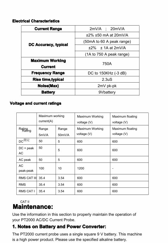
CurrentCurrentCurrentCurrent RangeRangeRangeRange 2mV/A ; 20mV/A
DCDCDCDC Accuracy,Accuracy,Accuracy,Accuracy, typicatypicatypicatypicallll
±2% ±50 mA at 20mV/A(50mA to 60 A peak range)
±2% ± 1A at 2mV/A(1A to 750 A peak range)
MaximumMaximumMaximumMaximum WorkingWorkingWorkingWorkingCurrentCurrentCurrentCurrent
750A
FrequencyFrequencyFrequencyFrequency RangeRangeRangeRange DC to 150KHz (-3 dB)RiseRiseRiseRise time,typicaltime,typicaltime,typicaltime,typical 2.3uS
Noise(Max)Noise(Max)Noise(Max)Noise(Max) 2mV pk-pkBatteryBatteryBatteryBattery 9Vbattery
Rating
測定
Maximum workingcurrent(A)
Maximum Working
voltage (V)
Maximum floating
voltage (V)
Rating Range
5mV/A
Range
50mV/A
Maximum Workingvoltage (V)
Maximum floatingvoltage (V)
DC 50 5 600 600
DC + peakAC
505 600 600
AC peak 50 5 600 600
ACpeak-peak
100 10 1200 -
RMS CAT III 35.4 3.54 600 600
RMS
CAT II
35.4 3.54 600 600
RMS CAT I 35.4 3.54 600 600

As the battery in the PT2000 current probe is drained, significant gainerrors may occur. The green LED will continue to light until a low batteryvoltage of 6.5 V is reached.
If probe gain errors are detected, replace the battery with a fresh one.
If not using this item(more than 1 week),we suggest you remove the battery from the
compartment. This is because heating will result in battery leakage, and battery
electrolyte will rust the circuit board,thus creating major damage. Furthermore, batteries
are high pollution products and therefore by reducing their usage, we will in turn protect
the environment.This will avoid leakage of battery since the quality of the batteries issomething that is out of our control.
2.2.2.2. BatteryBatteryBatteryBattery Installation:Installation:Installation:Installation:(1) Remove the probe from the circuit.(2) Open the battery compartment by taking the cover off. Install/replace the battery.
(3) While observing polarity, attach the new alkaline battery to the batteryconnector buttons and place the battery in the specified area.
(4) Place the cover back and lightly tighten the cover inplace.
3.3.3.3. Cleaning:Cleaning:Cleaning:Cleaning:To clean the probe exterior, use a soft cloth dampened in a solution of milddetergent and water. To clean the core, open the jaw and clean theexposed core surfaces with a cotton swap dampened with isopropylalcohol (isopropanol). Lubricate the jaws mating surfaces with light oil.
Do not clean with solvents or abrasives. Do not immerse the probe.
4.4.4.4. PreparationPreparationPreparationPreparation forforforfor ShipmentShipmentShipmentShipmentOur company has designed a special box to be used for PT2000,convenient for storage and shipment. Please do not discard it.
If the original packaging is unfit for use or not available, use the followingpackaging guidelines:
(1) Use a sturdy shipping carton having inside dimensions at least one inchgreater than the probe dimensions.
(2) Put the probe into a plastic bag or wrap to protect it from dampness.
(3) Place the probe into the box and stabilize it with light packagingmaterial.
(4) Seal the carton with shipping tape.
Specifications:Specifications:Specifications:Specifications:These characteristics apply to an adjusted PT2000 AC/DC Current Probe

installed on an oscilloscope of any brand. The oscilloscope must bewarmed up for at least 20 minutes and be in an environment with thetemperature at 10~30 and the humidity at 0~80.
Detail:Detail:Detail:Detail:
EnvironmentalEnvironmentalEnvironmentalEnvironmental CharacteristicsCharacteristicsCharacteristicsCharacteristics
ReplaceableReplaceableReplaceableReplaceable Parts:Parts:Parts:Parts:TheTheTheThe PPPPT2000T2000T2000T2000 AC/DCAC/DCAC/DCAC/DC CurrentCurrentCurrentCurrent ProbeProbeProbeProbe isisisis shippedshippedshippedshipped withwithwithwith thethethethe followingfollowingfollowingfollowing items:items:items:items:
One instruction manualOne 9V battery
RecommendedRecommendedRecommendedRecommended accessoryaccessoryaccessoryaccessory forforforfor useuseuseuse withwithwithwith digitaldigitaldigitaldigital meter:meter:meter:meter:
One BNC to banana plug adapterProduct number MT-246N. Designed with color fool proof design to avoidpolarity mistake when connecting to digital meter.
The PT2000 series does not have any user repairable assemblies. If you shouldhave trouble with your probe, contact your local Service Center orrepresentative for help.
SizeSizeSizeSize 231 mm x67 mm x 36 mm
MaximumMaximumMaximumMaximum ConductorConductorConductorConductorSizeSizeSizeSize
10.3 mm
CableCableCableCable LengthLengthLengthLength 200 cm
WeightWeightWeightWeight 310 g (without battery)
TemperatureTemperatureTemperatureTemperatureWorkingWorkingWorkingWorking
StorageStorageStorageStorage
0°C to +50°C
(+32°F to +122°F)
-20°C to +80°C
(-4°F to +176°F)
HumidityHumidityHumidityHumidity 0°C to 40°C, 95% humidity40°C to 50°C, 45% humidity
PollutionPollutionPollutionPollution DegreeDegreeDegreeDegree 2
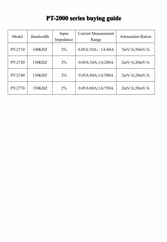
PT-2000PT-2000PT-2000PT-2000 seriesseriesseriesseries buyingbuyingbuyingbuying guideguideguideguide
Model BandwidthInput
ImpedanceCurrent Measurement
RangeAttenuation Ration
PT-2710 100KHZ 2% 0.05A/10A;1A/60A 5mV/A;50mV/A
PT-2720 150KHZ 2% 0.05A/10A;1A/200A 2mV/A;20mV/A
PT-2740 150KHZ 2% 0.05A/60A;1A/500A 2mV/A;20mV/A
PT-2770 150KHZ 2% 0.05A/60A;1A/750A 2mV/A;20mV/A