50 amp ac/dc current probe - tm atlantic · 50 amp ac/dc current probe pa-655 ... use the zero...
TRANSCRIPT

安培 交流/直流 電流探測鉗
DC‐500KHz. 5mA‐50A
INSTRUCTION MANUAL
50 Amp AC/DC Current Probe
PA-655
www.tmatlantic.com

2
TABLE OF CONTENTS General Safety Instructions------------------------------------------------- 4 Safety Terms and Symbols-------------------------------------------------- 5 Getting Started------------------------------------------------------------------6 Basic Operation-----------------------------------------------------------------8 Maintenance--------------------------------------------------------------------10 Specifications------------------------------------------------------------------13 Replaceable Parts-------------------------------------------------------------19 Accessories---------------------------------------------------------------------20
www.tmatlantic.com

3
PA-655 50 Amp AC/DC Current Probe
www.tmatlantic.com
4
General Safety Instructions:
Read the following safety instructions to avoid injury and prevent damage to this product or any products connected to it. Use this product only as specified. Only qualified personnel should perform service procedures.
To Avoid Fire or Personal Injury
Connect and Disconnect Properly. Connect the probe output to the measurement instrument before connecting the probe to the circuit under test. Disconnect the probe input and the probe ground from the circuit under test before disconnecting the probe from the measurement instrument.
Observe All Terminal Ratings. To avoid fire or shock hazard, observe all rating and markings on the product. Consult the instruction manual for further ratings information before making connections to the product.
Replace Batteries Properly. Replace batteries only with the proper type and rating specified.
Do Not Operate Without Covers. Do not operate this product without the covers or panels.
Avoid Exposed Circuitry. Do not touch exposed connections and components when power is present.
Do Not Operate With Suspected Failures. If you suspect there is damage to this product, have it inspected by qualified service personnel.
Do Not Operate in Wet/Damp Conditions.
Do Not Operate in an Explosive Atmosphere.
Keep Product Surfaces Clean and Dry.
www.tmatlantic.com
5
Safety Terms and Symbols: Terms in This Manual. These terms may appear in this manual:
WARNING. Warning statements identify conditions or practices that could result in injury or loss of life.
CAUTION. Caution statements identify conditions or practices that could result in damage to this product or other property.
Terms on the Product. These terms may appear on the product:
DANGER indicates an injury hazard immediately accessible as you read the marking.
WARNING indicates an injury hazard not immediately accessible as you read the marking.
CAUTION indicates a hazard to property including the product.
Symbols on the Product. These symbols may appear on the product:
Attention refer to operation Instructions.
This instrument has double insulation.
www.tmatlantic.com
6
Getting Started:
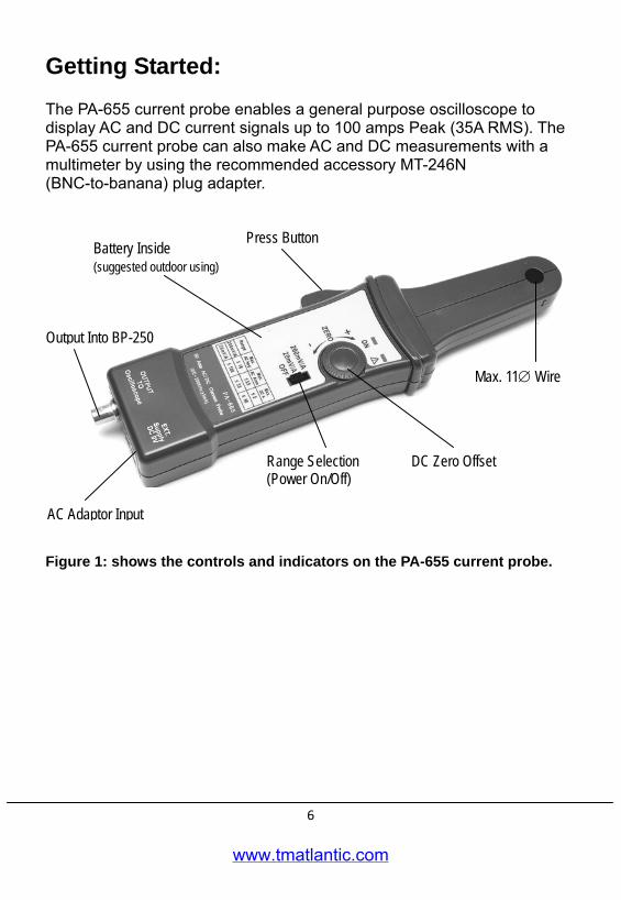
The PA-655 current probe enables a general purpose oscilloscope to display AC and DC current signals up to 100 amps Peak (35A RMS). The PA-655 current probe can also make AC and DC measurements with a multimeter by using the recommended accessory MT-246N (BNC-to-banana) plug adapter.
Figure 1: shows the controls and indicators on the PA-655 current probe.
Press Button Battery Inside (suggested outdoor using)
Max. 11∅ Wire
DC Zero Offset Range Selection (Power On/Off)
Output Into BP-250
AC Adaptor Input
www.tmatlantic.com
7
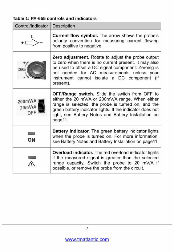
Table 1: PA-655 controls and indicators Control/Indicator Description
Current flow symbol. The arrow shows the probe’s polarity convention for measuring current flowing from positive to negative.
Zero adjustment. Rotate to adjust the probe output to zero when there is no current present. It may also be used to offset a DC signal component. Zeroing is not needed for AC measurements unless your instrument cannot isolate a DC component (if present).
OFF/Range switch. Slide the switch from OFF to either the 20 mV/A or 200mV/A range. When either range is selected, the probe is turned on, and the green battery indicator lights. If the indicator does not light, see Battery Notes and Battery Installation on page11.
Battery indicator. The green battery indicator lights when the probe is turned on. For more information, see Battery Notes and Battery Installation on page11.
Overload indicator. The red overload indicator lights if the measured signal is greater than the selected range capacity. Switch the probe to 20 mV/A if possible, or remove the probe from the circuit.
www.tmatlantic.com
8
Basic Operation: Before using the probe, the batteries or specified power adaptor must be installed. See the battery installation instructions on page11.
WARNING!
Do not clamp the probe onto circuits with voltages greater than 600 VAC. Personal injury or damage to the probe may result. Always connect the PA-655 current probe output to the instrument before clamping onto the circuit under test. 1. First connect the current probe BNC connector to BP-250 (double BNC
connection cable) then connect to oscilloscope input. Start by setting the oscilloscope voltage input channel to DC volts, and the voltage sensitivity scale to 0.1 V/div.
2. Move the OFF/ Range switch to the 20 mV/A or 200 mV/A position to turn on the probe. (※The PA-655 current probe has a green LED power/battery indicator. If the LED does not light, replace the battery or use specified power adaptor.)
3. Use the ZERO adjustment to zero or offset the probe output detection of residual magnetic DC charges.
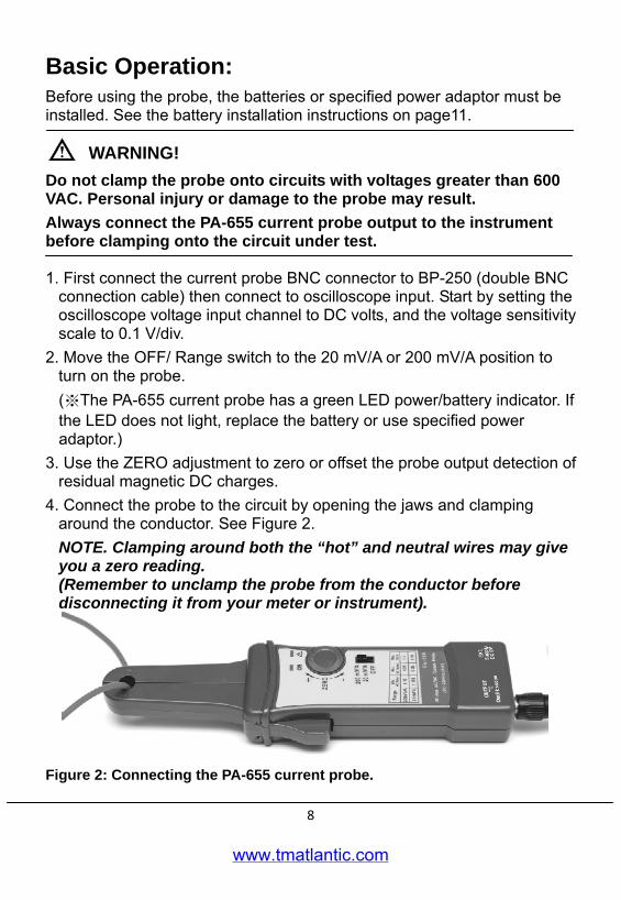
4. Connect the probe to the circuit by opening the jaws and clamping around the conductor. See Figure 2. NOTE. Clamping around both the “hot” and neutral wires may give you a zero reading. (Remember to unclamp the probe from the conductor before disconnecting it from your meter or instrument).
Figure 2: Connecting the PA-655 current probe.
www.tmatlantic.com
9
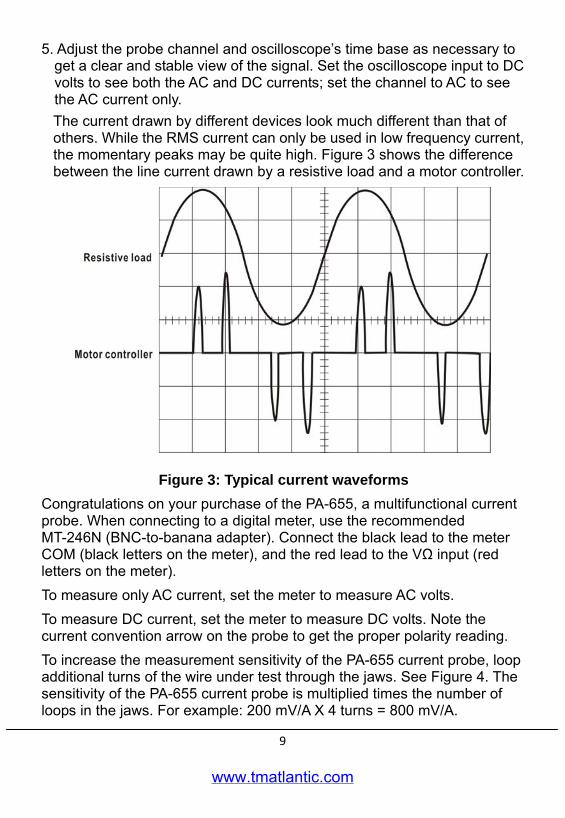
5. Adjust the probe channel and oscilloscope’s time base as necessary to get a clear and stable view of the signal. Set the oscilloscope input to DC volts to see both the AC and DC currents; set the channel to AC to see the AC current only. The current drawn by different devices look much different than that of others. While the RMS current can only be used in low frequency current, the momentary peaks may be quite high. Figure 3 shows the difference between the line current drawn by a resistive load and a motor controller.
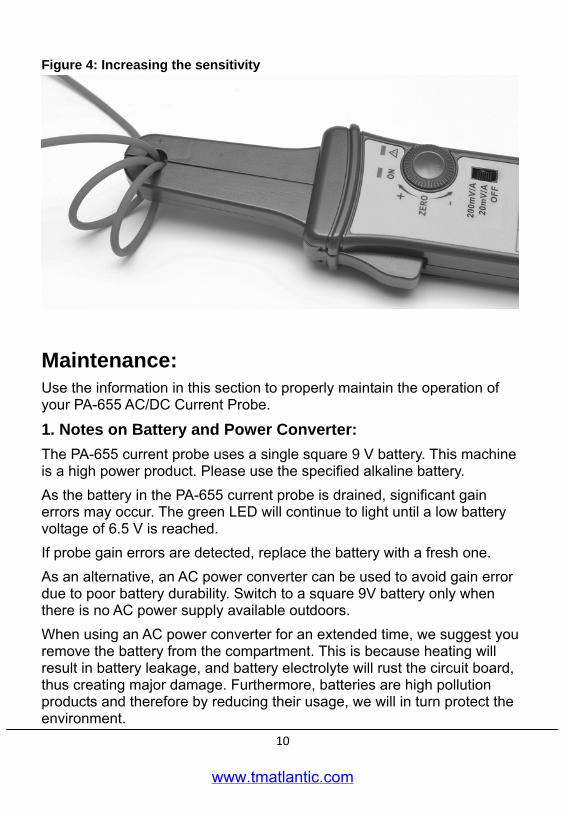
Figure 3: Typical current waveforms Congratulations on your purchase of the PA-655, a multifunctional current probe. When connecting to a digital meter, use the recommended MT-246N (BNC-to-banana adapter). Connect the black lead to the meter COM (black letters on the meter), and the red lead to the VΩ input (red letters on the meter). To measure only AC current, set the meter to measure AC volts. To measure DC current, set the meter to measure DC volts. Note the current convention arrow on the probe to get the proper polarity reading. To increase the measurement sensitivity of the PA-655 current probe, loop additional turns of the wire under test through the jaws. See Figure 4. The sensitivity of the PA-655 current probe is multiplied times the number of loops in the jaws. For example: 200 mV/A X 4 turns = 800 mV/A.
www.tmatlantic.com
10
Figure 4: Increasing the sensitivity
Maintenance: Use the information in this section to properly maintain the operation of your PA-655 AC/DC Current Probe.
1. Notes on Battery and Power Converter: The PA-655 current probe uses a single square 9 V battery. This machine is a high power product. Please use the specified alkaline battery. As the battery in the PA-655 current probe is drained, significant gain errors may occur. The green LED will continue to light until a low battery voltage of 6.5 V is reached. If probe gain errors are detected, replace the battery with a fresh one. As an alternative, an AC power converter can be used to avoid gain error due to poor battery durability. Switch to a square 9V battery only when there is no AC power supply available outdoors. When using an AC power converter for an extended time, we suggest you remove the battery from the compartment. This is because heating will result in battery leakage, and battery electrolyte will rust the circuit board, thus creating major damage. Furthermore, batteries are high pollution products and therefore by reducing their usage, we will in turn protect the environment.
www.tmatlantic.com

11
PA-655 has in its design a priority external power circuit therefore it is safe to simultaneously install the battery and the external power supply. During usage, removing the external power supply will not produce waveform anomaly or any damage. However when external power is used for an extended time (more than 1 week), removal of battery is recommended. This will avoid leakage of battery since the quality of the batteries is something that is out of our control. 2. Battery Installation: (1) Remove the probe from the circuit. (2) Open the battery compartment by loosening the three screws (uses
standard 3x15) and take the cover off. Install/replace the battery. (3) While observing polarity, attach the new alkaline battery to the battery
connector buttons and place the battery in the specified area. (4) Place the cover back and lightly tighten the screws to hold the cover in
place.
Figure 5: PA-655 Battery Installation
9V Battery
www.tmatlantic.com
12
3. Cleaning: To clean the probe exterior, use a soft cloth dampened in a solution of mild detergent and water. To clean the core, open the jaw and clean the exposed core surfaces with a cotton swap dampened with isopropyl alcohol (isopropanol). Lubricate the jaws mating surfaces with light oil. Do not clean with solvents or abrasives. Do not immerse the probe.
4. Preparation for Shipment Our company has designed a special box to be used for PA-655, convenient for storage and shipment. Please do not discard it. If the original packaging is unfit for use or not available, use the following packaging guidelines: (1) Use a sturdy shipping carton having inside dimensions at least one inch
greater than the probe dimensions. (2) Put the probe into a plastic bag or wrap to protect it from dampness. (3) Place the probe into the box and stabilize it with light packaging
material. (4) Seal the carton with shipping tape.
www.tmatlantic.com

13
Specifications: These characteristics apply to an adjusted PA-655 AC/DC Current Probe installed on an oscilloscope of any brand. The oscilloscope must be warmed up for at least 20 minutes and be in an environment with the temperature at 10~30 and the humidity at 0~80.
Table 2: Electrical Characteristics
Current Ranges 20/200 mV/A
DC Accuracy, typical ±3% ±30 mA at 200 mV/A (30 mA to 5 A peak range)
±4% ±300 mA at 20 mV/A (300 mA to 20 A peak range)
±15% max at 200 mV/A (20 A peak to 50 A peak range)
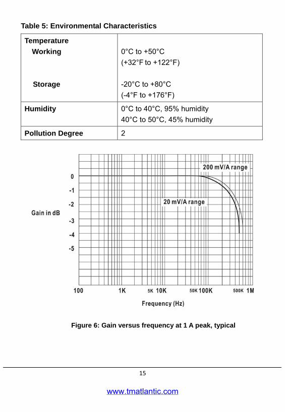
Gain versus frequency, typical See Figure 6
Maximum Working Current See Table 3
Maximum Working Voltage See Table 3
Maximum Float Voltage See Table 3
Frequency Range DC to 500 kHz (-3 dB)
Rise Time 0.7 μS (Typ.)
Battery Type and Life, typical 9V NEDA 1604A, IEC 6LR61 13 hours minimum (1 each)
DC signal linearity, typical See Figure 8
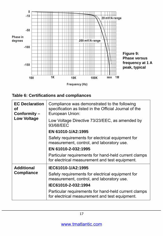
Phase shift, typical See Figure 9
www.tmatlantic.com
14
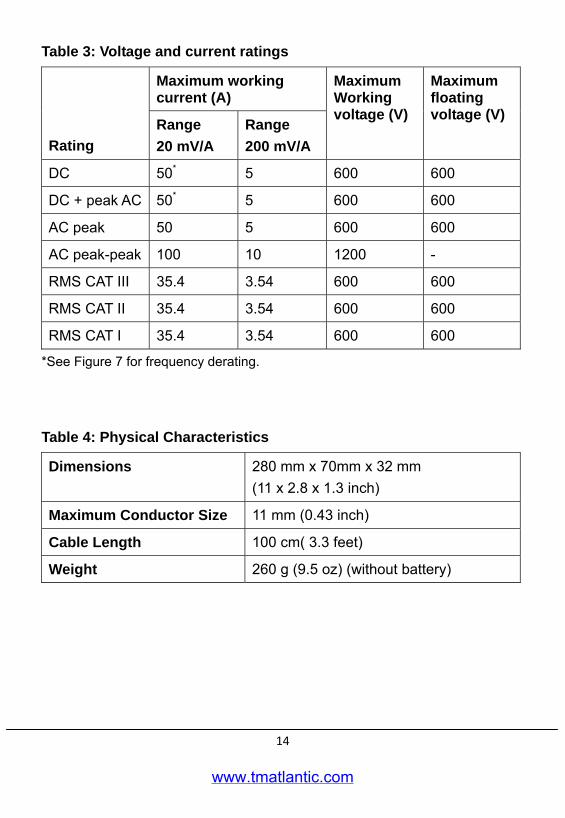
Table 3: Voltage and current ratings
Maximum working current (A)
Rating Range 20 mV/A
Range 200 mV/A
Maximum Working voltage (V)
Maximum floating voltage (V)
DC 50* 5 600 600
DC + peak AC 50* 5 600 600
AC peak 50 5 600 600
AC peak-peak 100 10 1200 -
RMS CAT III 35.4 3.54 600 600
RMS CAT II 35.4 3.54 600 600
RMS CAT I 35.4 3.54 600 600
*See Figure 7 for frequency derating.
Table 4: Physical Characteristics
Dimensions 280 mm x 70mm x 32 mm (11 x 2.8 x 1.3 inch)
Maximum Conductor Size 11 mm (0.43 inch)
Cable Length 100 cm( 3.3 feet)
Weight 260 g (9.5 oz) (without battery)
www.tmatlantic.com
15
Table 5: Environmental Characteristics
Temperature Working
Storage
0°C to +50°C (+32°F to +122°F) -20°C to +80°C (-4°F to +176°F)
Humidity 0°C to 40°C, 95% humidity 40°C to 50°C, 45% humidity
Pollution Degree 2
Figure 6: Gain versus frequency at 1 A peak, typical
www.tmatlantic.com

16
Figure 7: Maximum current versus frequency
Figure 8: DC signal linearity in the 20 mV/A range, typical
www.tmatlantic.com
17
Table 6: Certifications and compliances
EC Declaration of Conformity – Low Voltage
Compliance was demonstrated to the following specification as listed in the Official Journal of the European Union: Low Voltage Directive 73/23/EEC, as amended by 93/68/EEC EN 61010-1/A2:1995 Safety requirements for electrical equipment for measurement, control, and laboratory use. EN 61010-2-032:1995 Particular requirements for hand-held current clamps for electrical measurement and test equipment.
Additional Compliance
IEC61010-1/A2:1995 Safety requirements for electrical equipment for measurement, control, and laboratory use. IEC61010-2-032:1994 Particular requirements for hand-held current clamps for electrical measurement and test equipment.
Figure 9: Phase versus frequency at 1 A peak, typical
www.tmatlantic.com
18
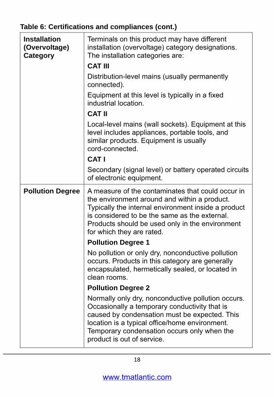
Table 6: Certifications and compliances (cont.)
Installation (Overvoltage) Category
Terminals on this product may have different installation (overvoltage) category designations. The installation categories are: CAT III Distribution-level mains (usually permanently connected). Equipment at this level is typically in a fixed industrial location. CAT II Local-level mains (wall sockets). Equipment at this level includes appliances, portable tools, and similar products. Equipment is usually cord-connected. CAT I Secondary (signal level) or battery operated circuits of electronic equipment.
Pollution Degree
A measure of the contaminates that could occur in the environment around and within a product. Typically the internal environment inside a product is considered to be the same as the external. Products should be used only in the environment for which they are rated. Pollution Degree 1 No pollution or only dry, nonconductive pollution occurs. Products in this category are generally encapsulated, hermetically sealed, or located in clean rooms. Pollution Degree 2 Normally only dry, nonconductive pollution occurs. Occasionally a temporary conductivity that is caused by condensation must be expected. This location is a typical office/home environment. Temporary condensation occurs only when the product is out of service.
www.tmatlantic.com
19
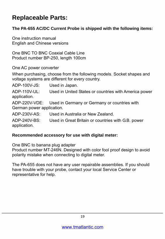
Replaceable Parts: The PA-655 AC/DC Current Probe is shipped with the following items: One instruction manual English and Chinese versions One BNC TO BNC Coaxial Cable Line Product number BP-250, length 100cm One AC power converter When purchasing, choose from the following models. Socket shapes and voltage systems are different for every country. ADP-100V-JS: Used in Japan. ADP-110V-UL: Used in United States or countries with America power application. ADP-220V-VDE: Used in Germany or Germany or countries with German power application. ADP-230V-AS: Used in Australia or New Zealand. ADP-240V-BS: Used in Great Britain or countries with G.B. power application. Recommended accessory for use with digital meter: One BNC to banana plug adapter Product number MT-246N. Designed with color fool proof design to avoid polarity mistake when connecting to digital meter. The PA-655 does not have any user repairable assemblies. If you should have trouble with your probe, contact your local Service Center or representative for help.
www.tmatlantic.com
нл
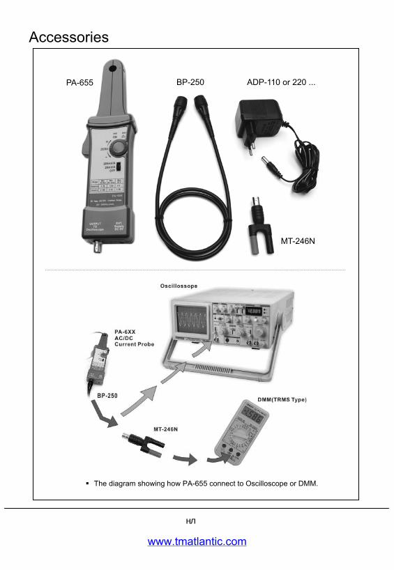
Accessories
ADP-110 or 220 ...
MT-246N
BP-250PA-655
The diagram showing how PA-655 connect to Oscilloscope or DMM.
www.tmatlantic.com