prepared by - homepage – us ignite
TRANSCRIPT

Response to US Ignite
RF Network 100% Submission
20 Jan 2020
PREPARED BY:
Jim Harding
Senior Project Manager
(207) 521-4106 | [email protected]

tilsontech.com
Jim Harding
Senior Project Manager
16 Middle Street, 4th Floor
Portland, ME 04101
(207) 521-4106
Scott Turnbull and Team
Dear Mr Turnbull and team: 20 January 2020
Puente Tilson JV, LLC is pleased to provide US Ignite with the attached 100% design submittal for the wireless
network supporting the Ft Carson AV pilot program. Puente Tilson JV, LLC is a joint venture between Tilson
Technology Management, Inc. and Puente Technology, LLC. Since 2007, Tilson has provided design,
engineering, and construction services to many clients seeking to improve their infrastructure. We believe that
we are well positioned to assist US Ignite with these services given our extensive experience and familiarity
with the project objectives. Puente Technology is a Service-Disabled Veteran-Owned Small Business that
provides a variety of construction management and IT services.
Tilson’s extensive expertise in all manner of wireless deployments, technologies, and turnkey project execution
provides the technical foundation for a seamless and successful project, while our partnership with Puente
satisfies US Ignite’s stated policy to comply with PL 99-661, Section 1207, regarding small business set-asides.
We thank you for your time in reviewing our design and we look forward to the possibility of working closely
with US Ignite in the deployment of this project. If you have any questions regarding our design, please contact
me at my direct line (207) 521-4106 or by email at [email protected]. We look forward to working on
this project with you further.
Sincerely,
Jim Harding
Sr. Project Manager

Contents
1 Design Philosophy ........................................................................................................................................ 1
1.1 Coverage .................................................................................................................................................. 1
1.2 Capacity ................................................................................................................................................... 1
1.3 Reliability ................................................................................................................................................ 1
1.4 Scalability................................................................................................................................................ 1
1.5 Longevity ................................................................................................................................................ 1
2 Wireless Technologies Review................................................................................................................ 2
2.1 Network Design and Project Plan – .............................................................................................. 2
3 Network Security .......................................................................................................................................... 6
3.1 Overall attributes of good security practices ............................................................................ 6
3.2 Physical Security .................................................................................................................................. 7
3.3 Transmission Security ....................................................................................................................... 7
3.4 Logical Security ................................................................................................................................. 10
4 Assumptions ................................................................................................................................................ 10
4.1 Node mount locations ..................................................................................................................... 10
4.2 Fiber Availability .............................................................................................................................. 10
4.3 FIPS2 Requirements ........................................................................................................................ 10
4.4 Throughput Requirements for sensors and mobile cameras .......................................... 10
5 Technical Data ............................................................................................................................................ 11
5.1 Equipment parameters (see attached spreadsheets for details) ................................... 11
5.2 RF Modeling Parameters ............................................................................................................... 11
6 Bill of Materials .......................................................................................................................................... 16
6.1 Radwin 5.8GHz Transportation/Mobility solution ............................................................. 16
6.2 LTE/CBRS Solution .......................................................................................................................... 18
7 Cost Proposal .............................................................................................................................................. 21
8 Recommendations, pros/cons for each system: ........................................................................... 22
8.1 Radwin 5.8: ......................................................................................................................................... 22
8.2 LTE/CBRS: ........................................................................................................................................... 23
9 Design tools ................................................................................................................................................. 23
9.1 EDX Signal Pro ................................................................................................................................... 23
9.2 Anritsu S412e ..................................................................................................................................... 24

tilsontech.com

| 1 |
RESPONSE TO US IGNITE
80% Design Submittal
SOLICITATION 6
1 Design Philosophy
1.1 Coverage Coverage is planned around the routes, devices and vehicles to be connected along those routes as provided.
Evaluating surrounding building heights and construction methods, flora type, heights and density, along with other
land use definitions are factored in. Noise floors and spectrum availability are captured via drive tests, with the
results being evaluated and factored into the design. Review of available infrastructure for backhaul is also a factor
in the design, whether it be a fiber uplink or Point-to-Point RF backhaul. Output power, antenna azimuths and
down tilt are then calculated to provide targeted coverage only where desired without over-propagation.
Consideration of these factors allow precise node location selection in the design.
1.2 Capacity Capacity is planned around the calculated aggregated throughput requirements of the devices and vehicles to be
connected along those routes as provided. Capacity is planned with additional overhead available for occasional
bursts beyond baseline requirements to ensure the best possible customer experience.
1.3 Reliability Reliability is planned around the uptime requirements of the devices and vehicles to be connected along those
routes as specified by the RFP, often expressed in terms of “9’s”. 4 9’s uptime equates to network hardware
availability of 99.99% of the time, or only 8.6 seconds per day of downtime. 5 9’s , or 99.999% uptime equates to
only .9 seconds per day of downtime. Desired RF connectivity and wired (fiber) connectivity reliability needs are
factored in the design phase, with prediction tools estimating reliability. The goal is always to meet or exceed
requested/specified uptime. Geographically diverse fiber routes or stand-by RF backhaul links for each node and
local battery backups at each node location are additional precautions that can significantly improve/impact
network and hardware uptime.
1.4 Scalability Scalability is planned around estimated future throughput requirements of the devices and vehicles to be connected
along those routes as provided, in addition to future routes, vehicles and devices. Scalability is achieved by
designing systems with the ability to increase network capacity, the number of connected devices, and the number
of nodes requiring connection without significant upgrades or changes to the core network.
1.5 Longevity Longevity is achieved by designing the network using proven equipment and technology at or near the beginning
of their product lifecycle, as well as committed long-term support from the manufacturer to ensure parts, updates,
and technical support will be available for years to come.

| 2 |
RESPONSE TO US IGNITE
80% Design Submittal
SOLICITATION 6
2 Wireless Technologies Review Based on bandwidth requirements and the previously mentioned design philosophies, there were two primary
technologies reviewed:
• 5.8GHz spectrum Mobility solution with no hand-off – some lag between loss and re-acquisition of network
when moving from node to node
• Private LTE in CBRS band (3.5GHz) with hand-off– no lag or drop when moving from node to node with
proper design.
Radwin was the primary manufacturer reviewed and selected for the 5.8GHz mobility/transportation product, with
a demonstrated track record for product lifespan, reliability and factory support. Radwin is not FIPS2 certified but
will provide a statement of no Chinese or Russian chipsets used in their equipment.
Both Nokia and JMA solutions were reviewed for LTE, with both systems being able to meet the performance,
reliability and other specs. Each vendor takes a slightly different approach, and each has pro’s and con’s. JMA
provides a more attractive price point and an interesting solution to mitigate self-interference/SINR issues, however
Nokia provides a better path to 5G for futureproofing. Because of this, the Nokia solution is Tilson’s recommended
solution for this project.
2.1 Network Design and Project Plan – Puente-Tilson’s RF network design meets or exceeds the specified minimum throughputs for both the cameras and AV
shuttle telemetry, producing a minimum of 6mpbs upload speeds and 14mbps download speeds for the mobile portion.
A combination of omni antennas and carefully aimed sectorized antennas with specific down tilt were used to ensure
complete RF coverage each route in its entirety. Fiber is assumed to be available at each pole location as part of the
intended design. Should fiber not be available at each pole location, a point-to-point link to the nearest fiber pop will be
utilized to provide network coverage. The parking/charging stations will be built to successfully download the terabytes
of data within one overnight charging shift, and designs can be provided as soon as the locations are specified.
2.1.1 RF specifications:
The RF network was designed specifically to have:
• -102 RSRP minimum signal for handoff to the next cell for maximum availability, reliability, connectivity
and throughput at all times
The RF network utilized:
• 3 ea 3-sector cells
• 2 ea 2-sector cells
• 6 ea cells with omni-directional antenna
• 1 ea cell with integrated antenna

| 3 |
RESPONSE TO US IGNITE
80% Design Submittal
SOLICITATION 6
2.1.2 RF Network cell location and mounting
The designed location and mounting utilize either existing or new utility or light poles installed in the ROW along
the routes as needed. Mounting the cells closer to the drive path provides more consistent coverage of the drive
path and increases accessibility via bucket truck for future maintenance.
• Assumptions:
o Available power along the routes
o Available fiber along the routes
2.1.3 RF Network Hardware selection
The RF network design includes the three best options of:
• Radwin Mobility/Transportation product
o 5.8GHZ spectrum
o Similar uses already in production
o Specifically designed for transportation/vehicles
o Confirmed – no Chinese or Russian chipsets
o Bandwidth exceeds 1mpbs throughput per vehicle while mobile (actual speeds are >=50mbps)
o Number of nodes required for design:
▪ Approximately 12+/- nodes for northern route
▪ Approximately 9+/- nodes for southern route and airfield
▪ Actual coverage results may vary slightly on final number of nodes deployed
• JMA Simulcast LTE Solution
o 3.5 CBRS Spectrum
o Full 150MHz spectrum availability with no changes to hardware for scalable throughput
o Similar uses already in production
o Not vehicle exclusive
o Number of nodes required for design:
▪ Approximately 7+/- nodes for northern route
▪ Approximately 7+/- nodes for southern route and airfield
▪ Actual coverage results may vary slightly on final number of nodes deployed
o Carrier network availability for failover
▪ *paid service
• Nokia Solution (Recommended solution)
o 3.5 CBRS Spectrum
o Similar uses already in production
o Not vehicle exclusive, allowing for additional uses of existing network
o 4G speeds and capacity are expandable by adding an additional 20MHz channel
o Number of nodes required for design:
▪ Approximately 7+/- nodes for northern route
▪ Approximately 7+/- nodes for southern route and airfield
▪ Actual coverage results may vary slightly on final number of nodes deployed
o Carrier network availability for failover
▪ *paid service
| 4 |
RESPONSE TO US IGNITE
80% Design Submittal
SOLICITATION 6
2.1.4 Route Description
The network is proposed to be connected by fiber from each pole location back to the core.
A small NEMA rated cabinet will be mounted on each pole to house:
Power supply with UPS backup
Radio head
PoE switch
Fiber patch panel
Antenna sectors as specified in the design, varying per pole
Cables from radio head to antenna sectors

| 5 |
RESPONSE TO US IGNITE
80% Design Submittal
SOLICITATION 6
2.1.5 Charging Station Description
Charging station designs have not been finalized due to missing information regarding the location of the charging
stations; however, some basic assumptions can be made regarding equipment. Each vendor/technology has
recommended hardware packages for charging station uploads that will meet or exceed the necessary 300mbps
required for 1TB of data downloaded per 8 hour charging shift.
2.1.6 Project Plan
The project will have one PM and one construction manager. The project will require a total of three separate crews –
pole set crews, topsides install crews, and electrical/fiber crews, utilizing bucket truck and/or man-lift or crane to support
topsides installation on the poles, and trenching/boring equipment. Digsafe will be contacted prior to any underground
work. Flaggers will be provided if deemed necessary along the route. The estimated time to install, configure, test and
turn up 12 cell locations is approximately 62 days. Actual time start to finish may vary due to fiber and electrical
availability, weather, base access, and other unforeseeable obstacles.
• 1 crew – Carrier Wave generator drive tests to prove design prior to pole placement – 2 days
• 1 crew - 1 Pole set per day – 12 +/- days
• 1 crew - 1 cell build (multiple radios per pole) per two days* – 24 +/- days
• 1 crew 1 electrical tie in per two days** – 24 +/- days
• 1 crew 1 fiber tie in per two days** – 24 +/- days
* Topsides Radio/sector installations must run independent of cabinet electrical and fiber work due to overhead hazards.
**Fiber and electrical work can run concurrently to some degree.
2.1.7 Network Diagram LTE Design Proposed Northern Route
T1 Internet Connection
SD
Cisco 1720
BRIS/T
CONSOLE
AUXWIC 0 OK
OK
B2
B1
WIC 1 OK
DSUCPU
LNK100FDX
S3
LOOP
LP
SD
Cisco 1720
BRIS/T
CONSOLE
AUXWIC 0 OK
OK
B2
B1
WIC 1 OK
DSUCPU
LNK100FDX
S3
LOOP
LP
SD
Cisco 1720
BRIS/T
CONSOLE
AUXWIC 0 OK
OK
B2
B1
WIC 1 OK
DSUCPU
LNK100FDX
S3
LOOP
LP
SD
Cisco 1720
BRIS/T
CONSOLE
AUXWIC 0 OK
OK
B2
B1
WIC 1 OK
DSUCPU
LNK100FDX
S3
LOOP
LP
SD
Cisco 1720
BRIS/T
CONSOLE
AUXWIC 0 OK
OK
B2
B1
WIC 1 OK
DSUCPU
LNK100FDX
S3
LOOP
LP
SD
Cisco 1720
BRIS/T
CONSOLE
AUXWIC 0 OK
OK
B2
B1
WIC 1 OK
DSUCPU
LNK100FDX
S3
LOOP
LP
3_2 RRH
3_1 RRH
3_3 RRH
4_1 RRH
4_2 RRH
5_1 RHH
5_2 RHH
6_1 RRH
6_2 RRH
6_3 RRH
7_1 RRH
9_1 RRH
BBU
BBU
BBU
BBU
BBU
BBU
FIBER
FIBER
FIBER
FIBER
FIBER
FIBER
Fiber Provider COCustomer Core

| 6 |
RESPONSE TO US IGNITE
80% Design Submittal
SOLICITATION 6
3 Network Security
The proposed FT Carson communications system includes 4 components:
• Overall Attributes of Good Security Practices
• Physical Security
• Transmission Security (TRANSEC) 1. Fiber Circuits 2. Radwin 5.8 Mobility/Transportation solution 3. LTE options from JMA and Nokia
• Logical Security
We have closely evaluated these network elements and have identified the security best practices to secure and protect
the network. While there is no such thing as complete security in today’s world these practices offer the most protection
available.
3.1 Overall attributes of good security practices
There are several key components or principles of a successful, well managed security program. These components are
key and act as guiding principles to managers and employees in setting up and running a security program. These principles
are:
1. Commitment from Management 2. Involvement 3. Diligence 4. Security in depth 5. Monitoring
The first principle is for management to be committed to the security plan. This commitment must take the form of
willingness to invest resources (time, money, employees) into the overall security of the network and systems.
Management must understand the long term health and safety of the network is essential to the business or product it is
supporting being successful.
Security is everyone’s concern. It doesn’t fall to and stop with management to ensure that security policies are understood
and practiced. Every employee must be involved. Everyone is a security official!
Management must stay diligent and ensure that each employee is also doing his or her job to be a part of the overall
security plan. Setting up a plan and never checking on it, or not updating it is essentially the same as not having a security
plan.

| 7 |
RESPONSE TO US IGNITE
80% Design Submittal
SOLICITATION 6
Security in depth is vital. Security doesn’t stop at the door, or the gate. Security starts at the door or gate, or at the radio,
and continues to the other end of the link. It continues to the back room and the servers, and all the way to the desktop.
Security is all encompassing, and a successful security plan will address the multiple levels that must be secured.
Security must be monitored. Implementing login and entry security procedures are useless unless they are monitored.
Logs should be kept, doors should be locked, and CCTV should be monitored.
3.2 Physical Security
Physical security is sometimes referred to as the first line of defense because it is often the easiest way for someone to
gain access. Physical security is defined as that part of security concerned with physical measures designed to safeguard
and to prevent unauthorized access to equipment and material against sabotage, damage, and theft.
The following measures are vital to the physical security of this communications network and will be addressed during the
installation.
1. Barriers, locks, and keys a. All equipment accessible from ground level will have the ability to be locked. b. Roadside cabinets will be secured immediately upon installation. c. Roadside components will be constructed of materials of sufficient strength to offer protection against
tampering. d. Access to keys will be restricted to those individuals that require access and have been cleared to do so.
2. Maintenance a. A comprehensive maintenance plan will be instituted on the equipment deployed along the corridor.
This plan will ensure that equipment is – i. checked on a regular basis.
ii. That all mounted equipment is securely in place. iii. That rodents and insects do not invade the equipment.
3. Intrusion Detection and monitoring a. Any equipment that includes intrusion detection measures will be monitored.
4. Disaster prevention a. Equipment will be installed above water table levels and not in flood prone areas. b. Any equipment mounted to a structure will be secured and checked regularly as part of the
maintenance plan. c. Equipment chosen for deployment will be tolerant of the known weather conditions and will be capable
of operating nominally in such conditions. d. Equipment with known operating parameters that are outside of known weather conditions will be
done so in an HVAC controlled environment.
3.3 Transmission Security

| 8 |
RESPONSE TO US IGNITE
80% Design Submittal
SOLICITATION 6
The transmission portion of the network offers an attacker a likely way to gain access to the network. For this reason, each
component of the transmission network has been evaluated for security.
The fiber segments of the network represent the most secure forms of communications used. Because fiber is run
exclusively below ground, and the nature of fiber makes it very difficult to eavesdrop on. Due to these factors, fiber can
be considered inherently secure and thus does not require additional security measures.
3.3.1 Radwin 5.8 Mobility Solution
The Radwin solution is secured through a combination of encryption and protocols as outlined below:
RADWIN radios incorporate AES 128 bit integrated advanced encryption. The AES128 ensures user data protection with
one of the most sophisticated commercially available combined encryption and authentication techniques, CCM/AES.
This technique complies with the IEEE 802.11i (phase iii) recommendations. CCM/AES uses a symmetric 128-bit encryption
key (EK), and a nonce, providing both message encryption and signature authentication.
The nonce enables the receiver to remember already received genuine messages and reject all replayed messages.
Initial encryption and authentication is based on a user-defined master key (Link Password in addition to SSID).
The pre-defined encryption key is used for message authentication (preventing anti-spoofing and replay protection) and
access control (without the secret link password a unit cannot access the network).
It is possible to add black list mechanism to block previously authorized TMUs.
Because of the proprietary nature of the protocol it is impossible to try and hack from a 3rd party Wi-Fi AP, or even read
out parameters such as MAC addresses, which may be possible in some other standard Wi-Fi based systems.
3.3.2 LTE Solution
Both LTE solutions proposed follow 3GPP TS 33.401, and are described in NIST Special Publication 800-187 as:
“LTE introduced a new set of cryptographic algorithms and a significantly different key structure than that of previous
evolutions. There are 3 sets of cryptographic algorithms for both confidentiality and integrity termed EPS Encryption
Algorithms (EEA) and EPS Integrity Algorithms (EIA). EEA1 and EIA1 are based on SNOW 3G, very similar to algorithms used
in UMTS. EEA2 and EIA2 are based on the Advanced Encryption Standard (AES) with EEA2 defined by AES in CTR mode (e.g.,
stream cipher) and EIA2 defined by AES-CMAC (Cipherbased MAC). EEA3 and EIA3 are both based on a Chinese cipher ZUC
[5]. While these new algorithms have been introduced in LTE, network implementations commonly include older algorithms
for backward compatibility for legacy devices and cellular deployments. Many keys in LTE are 256-bits long, but in some
current implementations only the 128 least significant bits are used. The specification has allowed for a system-wide
upgrade from 128-bit to 256-bit keys.2 In LTE, the control and user planes may use different algorithms and key sizes.

| 9 |
RESPONSE TO US IGNITE
80% Design Submittal
SOLICITATION 6
The majority of technical security requirements are available within the primary LTE security specification – 3GPP TS 33.401
– EPS Security Architecture”
3.3.2.1 JMA Solution
JMA further defines their security as:
JMA Wireless operation management exploits four main security techniques:
1. Firewall
2. Security protocols (e.g., SSL and HTTPS)
3. Embedded VPN
4. Encrypted communication SNMPv3
Thus system security is maintained by allowing access only through secure communication protocols.
Moreover, four different account levels are available, providing different permissions to users accessing the system with
a username and robust password (at least 8 characters having at least three of the following criteria: upper case, lower
case, digits, and symbols). Only those with access to the supervision Operation Maintenance Terminal (OMT) webpage
(using a username and password) can activate new remote units (RU) following a discovery process. Without accessing
the supervision OMT graphical user interface (GUI) using secure credentials, no additional RUs can be commissioned and
deployed in the system.
3.3.2.2 Nokia Solution
Nokia further defines their security as:
“All customer data communication within the LTE user plane stays on-site and is exclusively routed towards customer-
defined networks. Management communication between the site and Nokia DAC is secured with TLS as per industry best
practice. The air interface between mobile equipment and access point is encrypted and integrity-protected as per
commercial LTE air interface standards. Nokia DAC network access authentication and authorization is based on Nokia
DAC SIM cards. Standard mutual authentication is performed between mobile device with Nokia DAC SIM card and
private Nokia DAC network. Other devices with for example commercial SIM cards cannot access the private network.
Nokia DAC regional cloud runs in Nokia-controlled data centers, fulfilling Tier III data center requirements, including the
same security standards applied for commercial mobile networks. Network security in current configurations is based on
SRX300 firewall, or optionally, on SRX345 with integrated mobile broadband WAN interface.”

| 10 |
RESPONSE TO US IGNITE
80% Design Submittal
SOLICITATION 6
3.4 Logical Security
Logical security consists of measure that can be put in place, and safeguards that can be enabled on systems themselves
to offer protection.
All systems and equipment that are deployed as part of this communications network along the corridor will have the
following security measures put in place.
1. All default passwords will be changed. This ensures that should physical access to a device be gained by a potential attacked they would not be able to gain control of the device using known, default passwords.
2. Devices that offer remote access will be secured in several ways. a. If possible telnet access will be disabled. Telnet is inherently unsecure as all information is transmitted in
the open, to include passwords. b. SSH where available will be required. c. HTTP access will be disabled, required HTTPS to gain remote access. d. Access will be restricted to known networks by IP address.
3. Additional and unused ports on equipment will be disabled and put into a null VLAN where possible. This will ensure that should physical access be gained to a cabinet a potential attacker cannot simply plug-in and gain access to the network.
4. Where possible separate user accounts will be created and used. This allows for more accurate logging and tracking of user access into devices.
This plan like any good security practice is a living document and subject to changes in response to threats.
4 Assumptions
4.1 Node mount locations Power along the routes is accessible and deliverable to pole locations
4.2 Fiber Availability Fiber along the routes is accessible and deliverable to pole locations
4.3 FIPS2 Requirements FIPS2 has been identified as an ideal vs a requirement. Chipsets from manufacturer must be confirmed as not
Chinese or Russian origin.
4.4 Throughput Requirements for sensors and mobile cameras Throughput is determined as 1mpbs for cameras. Sensor throughput will be minimal due to the nature/size of
the data.

| 11 |
RESPONSE TO US IGNITE
80% Design Submittal
SOLICITATION 6
5 Technical Data
5.1 Equipment parameters (see attached spreadsheets for details) Mounting height: varied from 25’-45’ as needed to provide coverage
5.1.1 Radwin 5.8
Radio Transmit gain
Antenna gain
* will be in 100% submittal
5.1.2 LTE 3.5 CBRS
Radio transmit gain: Designed to maximum of 50W EIRP per FCC regulations
Antenna gain: from 12dBi to 17dBi, specific to each pole location and sector application
5.2 RF Modeling Parameters
5.2.1 Radwin 5.8 Mobility/Transport Product
Proprietary Radwin RPlanner tool
No ground clutter attenuation factored in design due to software limitations
5.2.2 LTE/CBRS:
EDX Signal Pro v9.2
Cirrus ground clutter and terrain data resolution: 10m hybrid
Propagation model used: Anderson 2.0+
Minimum designed RSRP at handoff: -102
3D buildings modeled for attenuation/refraction
Flora heights and attenuation adjusted specifically for local conditions
Sample CBRS Sector data: (additional, complete data in attached CSVs)

| 12 |
RESPONSE TO US IGNITE
80% Design Submittal
SOLICITATION 6
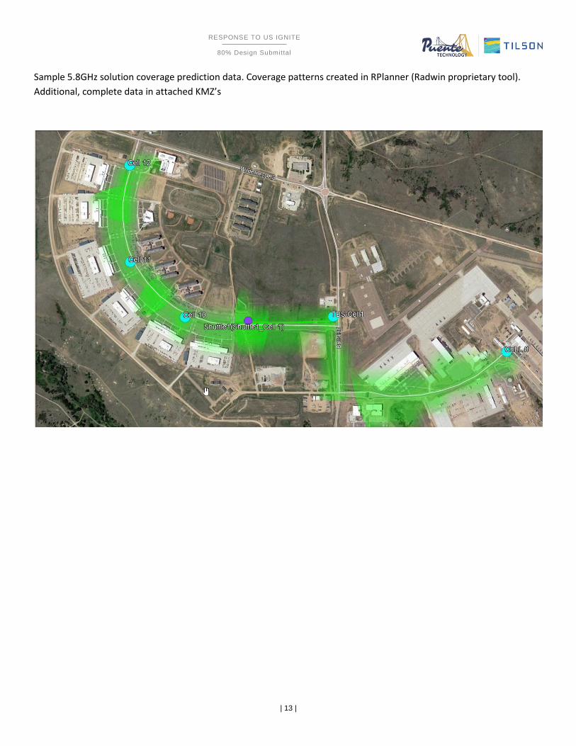
Sample 5.8GHz solution coverage prediction data. Coverage patterns created in RPlanner (Radwin proprietary tool).
Additional, complete data in attached KMZ’s
| 13 |
RESPONSE TO US IGNITE
80% Design Submittal
SOLICITATION 6
Sample 5.8GHz solution coverage prediction data. Coverage patterns created in RPlanner (Radwin proprietary tool).
Additional, complete data in attached KMZ’s

| 14 |
RESPONSE TO US IGNITE
80% Design Submittal
SOLICITATION 6
Sample LTE/CBRS coverage prediction data: Coverage patterns created in EDX Signal Pro. Additional, complete data in
attached KMZ’s.

| 15 |
RESPONSE TO US IGNITE
80% Design Submittal
SOLICITATION 6

| 16 |
RESPONSE TO US IGNITE
80% Design Submittal
SOLICITATION 6
6 Bill of Materials
6.1 Radwin 5.8GHz Transportation/Mobility solution $188,618

| 17 |
RESPONSE TO US IGNITE
80% Design Submittal
SOLICITATION 6
Trackside Radios & Antennas (16 sites+1 site in parking area)Radio & Antennas
RADWIN P/N Description
Outdoor
South Qty
Outdoor
North QtyParking Qty Unit Price
Extended
Price
RW-5T00-
0158
RADWIN TBS Transportation Base Station, Connectorized for external antenna (6 x N-type), supporting FCC
Regulation, up to 100Mbps of Aggregated Throughput, MIMO2x2, 40MHz CBW, 64QAM5 9 $ 6,750.00 $ 94,500.00
RW-5T00-
0458
RADWIN TBS 5T00 ODU, Connectorized for external antenna (6 x N-type), supporting FCC regulation, MIMO3x3,
80MHz CBW, 256QAM1 $ 10,800.00 $ 10,800.00
RW-9105-
5158Flat Antenna, Dual Polarization-Directional, Gain 19 dBi, Frequency Range 5.15 - 5.875 GHz 18 44 2 $ 230.40 $ 14,284.80
RW-9061-
5002Flat Antenna, Dual Polarization-Sectorial-60° , Gain 15 dBi, Frequency Range 4.9 - 6.06 GHz 2 $ 711.60 $ 1,423.20
RW-9061-
5001Flat Antenna, Dual Polarization-Sectorial-90° , Gain 14 dBi, Frequency Range 4.9 - 5.95 GHz 2 $ 711.60 $ 1,423.20
$ 122,431.20
Trackside AccessoriesOptional Accessories
RADWIN P/N Description
Outdoor
South Qty
Outdoor
North QtyParking Qty
RW-9921-
0080
Outdoor AC POE device for RADWIN's radios, with GBE interface, supports power range of 100-240VAC nominal
range. 90-264VAC max range; EU color wiring5 9 1 $ 270.00 $ 3,780.00
AT0040101 ODU-IDU Cable, 25 m w. Glend 5 9 1 $ 63.60 $ 890.40
RW-9911-
0005ODU-IDU Cable, 5 m 5 9 1 $ 40.80 $ 571.20
RW-9924-
0107
Kit of 10 Outdoor Lightning Protection Units for 10/100/1000Base-T PoE surge protector (including 0.5m CAT5e
cable and stainless steel pole mounting band)1 1 0 $ 900.00 $ 1,800.00
$ 7,041.60
Onboard Radios and Antennas (2 Shuttle Bus, 1xTMU per Shuttle)Radio & Antennas
RADWIN P/N Description Shuttle Qty Shuttle Qty
RW-5R00-
0158
RADWIN TMU Transportation Mobile Unit, Connectorized for external antenna (3 x N-type), supporting FCC
Regulation, up to 100Mbps of Aggregated Throughput, MIMO2x2, 40MHz CBW, 64QAM1 1 $ 4,200.00 $ 8,400.00
RW-9401-
5002 Omni Antenna, Vehicular Single-directional , Gain 12 dBi, Frequency Range 4.9 - 5.9 GHz 1 1 $ 585.60 $ 1,171.20
RW‐9401‐500
4Omni Antenna, Vehicular Bi-directional , Gain 12 dBi, Frequency Range 4.9 - 5.9 GHz 1 1 $ 1,080.00 $ 2,160.00
RW-9916-
0103RF Cable, 2.5 m, N-type to N-type, Railway Certified 3 3 $ 108.00 $ 648.00
$ 12,379.20
Onboard AccessoriesOptional Accessories
RADWIN P/N Description Shuttle Qty Shuttle Qty
RW-9921-
0110Outdoor DC POE device for RADWIN's radios, with GBE interface, supports power range of 10-60 VDC 1 1 $ 270.00 $ 540.00
RW-9917-
6102Railway standards - M12(m) to RJ45, 2m 1 1 $ 121.20 $ 242.40
RW-9911-
2025CAT5 ODU-OPOE Cable, 25m, assembled w/RJ45 connectors 1 1 $ 72.00 $ 144.00
$ 926.40
$ 142,778.40
Services
RADWIN P/N Description Qty
RW-8310-
0000
RF Planning Supervision:
RADWIN will provide guidance to the integrator for RF Planning per the different scenarios in the route (including
antennas placement & orientation in base stations and on trains), and will review the detailed planning and site
selection done by the integrator
1 $ 12,000.00 $ 12,000.00
RW-8320-
1000
Radio network engineering:
planning of integration to customer's onboard and wayside networks, frequency allocation, radio parameters
configuration (RF and networking), Synchronization
5 Days $ 8,400.00 $ 8,400.00
RW-8350-
1000
Site survey onsite support first week:
RADWIN engineer will accompany the integrator during the first week of site survey to provide guidelines on site
selection and planning. May include also site survey of train
3 Days $ 5,520.00 $ 5,520.00
RW-8130-
0000Installation Supervision - OJT training/Supervision of FIRST site and FIRST Train 3 Days $ 5,520.00 $ 5,520.00
RW-8130-
0000
Commissioning & Optimization
Radio network commissioning & Optimization after installation is finalized5 Days $ 7,200.00 $ 7,200.00
RW-8420-
1000
Training:
Training (TTT) for up to 10 personnel at customer's facility3 Days $ 7,200.00 $ 7,200.00
$ 45,840.00
$ 45,840.00
Total for Radio Network
Services
Total Services*

| 18 |
RESPONSE TO US IGNITE
80% Design Submittal
SOLICITATION 6
6.2 LTE/CBRS Solution JMA BOM - $218,427
Item Qty Unit Price
10 1 Each 1,863.00$
20 1 Each 1,863.00$
30 1 Each 2,277.00$
40 1 Each 2,277.00$
50 1 Each 1,210.96$
60 1 Each 1,647.72$
70 1 Each 2,869.02$
T o tal $ 14,007.70
SX08FRO230-01 2'x2' 8 Pt 30/30 Pnl Antenna 617-5925M Hz
DX12FRO260-20 2FT PNL XPOL 12P, 0 DEG, LB, HB, CBRS, L
SX10FRO165-01 1' XPOL 10 PORT 65/65 W/ INTEGRATED DIPS
SX08FRO128-01 1'x2' 8 Pt 65/28 Pnl Antenna 617-5925M Hz
DX10FRO260-06 2FT PNL XPOL 10 PORT LB,HB,CBRS,LAA 6FET
DX10FRO260-00 SFT PNL XPOL 10 PORT LB,HB,CBRS,LAA 0FET
DX12FRO260-26 2F XP 12P HB/CBRS/LAA FET 2,6,0,0
Antenna Details
ProductID Material Description

| 19 |
RESPONSE TO US IGNITE
80% Design Submittal
SOLICITATION 6
QTY Description Part Number Price Per Extended Price
25 Virtual Baseband Connected User Equipment Software License ‐
Perpetual
XS‐VBB‐CUE‐S L 208.42$ 5,210.40$
25 Virtual Baseband Connected User Equipment Software
Assurance Service ‐ Annua l
XS‐VBB‐CUE‐S AS 41.69$ 1,042.20$
25 Virtual Baseband UE Pooling License ‐ Re quire d 1:1 with
XS‐VBB‐CUE‐S L ‐ P e rpe tua l
XS‐VBB‐UEP L‐S L 34.73$ 868.20$
25 Virtual Baseband UE Pooling License Software Assurance
Service ‐ Annua l
XS‐VBB‐UEP L‐S AS 6.95$ 173.70$
‐ Annual licenses will be prorated based on full calendar months
remaining when the PO is received.
Note
‐ Annual licenses will automatically be renewed and invoiced the
first week of each calendar year.
Note
1 High‐e nd COTS se rve r AC powe re d ‐ (Tie r 2) De ll 740, 2x CP U
Intel Xeon Gold 6154, 18C @3.0GHz
THWPC‐R‐XT2AC 16,542.26$ 16,542.26$
1 PCI Express CPRI card, 9.81Gbps, 9 x SFP+ connectors, with
GPS receiver
TPCIE‐9L‐G1 7,450.80$ 7,450.80$
1 SFP+ Optical transceiver, 1310nm, single‐mode , non ‐BIDI, 10km XH‐S FP 131S ‐10G10 58.50$ 58.50$
2 Optical fiber patchcord, 2meters, singlemode, LC/UPC‐S C/AP C,
single fiber
XH‐FO2S ‐LUS A‐S 15.60$ 31.20$
1 XRAN HW NETWORK CARD 1/10G, 2 PORTS, SFP+ (Mellanox
MCX4121A‐XCAT)
XH‐NIC‐M‐10G2 615.42$ 615.42$
1 Active GPS Antenna, IP67 XH‐GP S ‐ANT 198.90$ 198.90$ 1 EMP Protector for GPS Antenna, IP67 XH‐GP S ‐EMP 464.10$ 464.10$ 1 Bracket, GPS antenna, Stainless steel, L bracket 23‐0040 ‐1 27.30$ 27.30$ 1 Adapter, SMA‐M to N‐F, GP S c oa x c onne c tion 586445 31.20$ 31.20$ ‐ ‐ ‐
‐ South Campus ‐
6 TEKO Cell Hub Radio Unit, CBRS Band 48, high‐powe r, MIMO
2x2, DC, 2.2‐5, inc lude s 3x XR‐CH‐CUC
XR35WM2/48Y 8,278.66$ 49,671.94$
12 Jumper, 4.3‐10 M to 2.2 ‐5 M, 1/4", 3 Foot, P le num JMA‐4M2M‐14S P ‐3 71.39$ 856.66$ 6 SFP+ Optical transceiver, 1270/1330nm, single‐mode , BIDI, 10G,
10km
XH‐S FP 23S B‐10G10 171.60$ 1,029.60$
6 SFP+ Optical transceiver, 1330/1270nm, single‐mode , BIDI, 10G,
10km
XH‐S FP 32S B‐10G10 171.60$ 1,029.60$
‐ ‐ ‐
‐ North Campus ‐
12 TEKO Cell Hub Radio Unit, CBRS Band 48, high‐powe r, MIMO
2x2, DC, 2.2‐5, inc lude s 3x XR‐CH‐CUC
XR35WM2/48Y 8,278.66$ 99,343.87$
26 Jumper, 4.3‐10 M to 2.2 ‐5 M, 1/4", 3 Foot, P le num JMA‐4M2M‐14S P ‐3 71.39$ 1,856.09$ 12 SFP+ Optical transceiver, 1270/1330nm, single‐mode , BIDI, 10G,
10km
XH‐S FP 23S B‐10G10 171.60$ 2,059.20$
12 SFP+ Optical transceiver, 1330/1270nm, single‐mode , BIDI, 10G,
10km
XH‐S FP 32S B‐10G10 171.60$ 2,059.20$
‐ ‐ ‐
1 XRAN Server Commissioning CMSV 13,800.00$ 13,800.00$ ‐
‐
‐
‐
‐
‐
‐
Comments
: Tax and Shipping not included 204,420.34$

| 20 |
RESPONSE TO US IGNITE
80% Design Submittal
SOLICITATION 6
Nokia BOM (Recommended Solution) $510,285

| 21 |
RESPONSE TO US IGNITE
80% Design Submittal
SOLICITATION 6
7 Cost Proposal Costs for pole installations are budgetary due to unconfirmed power and fiber availablility and delayed vendor pricing:
Part Number Description QTY List Unit Cost Extended Cost
Option 1 -- 2x2 small cell solution
Nokia Digital Automation Cloud (NDAC) is the basis for
this proivate LTE solution, refer to the attached
technical description
SKNDALLN1016 NDAC Large Edge Kit 1 N/A $51,741.60 $51,741.60
SKNDALLN1020 NDAC Micro 4G AP Kit US B48 Dir 7 N/A $12,225.60 $85,579.20
SKNDALLN1021 NDAC Micro 4G AP Kit US B48 Omni 6 N/A $12,225.60 $73,353.60
NDAC cloud core connectivity and subscriptions
SSNDBACN1020 Micro Connectivity Sector (Monthly) 12 mos per AP (9)N/A $93,312.00
SSNDBACN1020 Micro Connectivity Sector (Monthly) 12 mos per AP (6)N/A $62,208.00
SSNDBACN1024 Large Edge Connectivity N/A $31,104.00
Total $397,298.40
Option 2 -- 4x4 small cell solution
Nokia Digital Automation Cloud is the basis for this
proivate LTE solution, refer to the attached technical
description
SKNDALLN1016 NDAC Large Edge Kit 1 N/A $51,825.60
HWNDANTN1023 AW3089 3300-3800 11.0dbi T4 Omni Ant 6 N/A $1,713.60 $10,281.60
HWNDBASN1033 ABIA AirScale Capacity unit 3 N/A $6,897.60 $20,692.80
SKNDACPN1023 NDAC Airscale 4G Outdoor Base Band Kit 1 N/A $17,265.60 $17,265.60
SKNDACPN1036 NDAC Airscale Micro RRH Kit B48 12 N/A $8,625.60 $103,507.20
SKNDACPN1047 NDAC Airscale Micro RRH Kit B48 no ant 6 N/A $8,625.60 $51,753.60
$0.00
NDAC cloud core connectivity and subscriptions $0.00
SSNDBACN1020Micro Connectivity Sector (Monthly) 12 mos per AP
(14) N/A $145,152.00
SSNDBACN1020Micro Connectivity Sector (Monthly) 12 mos per AP (6) N/A $62,208.00
SSNDBACN1024 Large Edge Connectivity N/A $30,348.00
Total $493,034.40

| 22 |
RESPONSE TO US IGNITE
80% Design Submittal
SOLICITATION 6
Item Desc. Cost Qty Extended Cost
Utility Pole Class 3 25’ AGL $2500 1 $2500
Utility Pole Class 3 30’ AGL $2500 4 $10000
Utility Pole Class 3 35’ AGL $3000 1 $3000
Utility Pole Class 3 40’ AGL $3500 2 $7000
Utility Pole Class 3 45’ AGL $4000 2 $8000
Node/Sector
installation
Pole mount equipment, optimize sector $4000 10 $40000
Power Connect pole to commercial power $2500 10 $25000
Fiber Trench or horizontal bore from termination to pole $35/ft Unknown
Fiber Pull, install and splice/terminate fiber (including
materials and handhole)
$2500 10 $25000
Total Cost to deploy $120,500
Puente Tilson JV has taken every opportunity to ensure a conservative, robust RF design. As an industry best practice
during actual pole deployments, each route will be tested on-site for coverage from a CW at elevation prior to pole
placement to ensure only what is needed for coverage is deployed. As such, the actual number of poles may vary.
8 Recommendations, pros/cons for each system:
8.1 Radwin 5.8: • Pros
o Massive throughput with current technology
o Extremely competitive pricing as compared to LTE Solutions
o Excellent manufacturer’s support
o Demonstrated successful, reliable product
o Secure
• Cons
o No path to 5G without major network overhaul
o No direct path to carrier for network redundancy without additional hardware on shuttles

| 23 |
RESPONSE TO US IGNITE
80% Design Submittal
SOLICITATION 6
8.2 `
LTE/CBRS: FOR BOTH OPTIONS:
• Recommend obtaining PAL for frequency licensing –
o Provides incumbent status for frequency use
o Helps mitigate potential interference issues from other emitters before they occur
• Recommend Google for SAS service
o $2.25 per attached device (UE)
o High resolution design and planning tools specific to CBRS, useful for future
design/deployments/expansions.
• JMA Pros
o ODAS architecture
o No hand-off due to Simulcast technology improves signal to noise ratio (SINR)
o Direct path to carrier fail-over for redundancy
o Significantly less cost than carrier-grade LTE
o Secure
o US-based company (Liverpool, NY)
• JMA Cons
o Power aggregation limitations due to Simulcast could impair additional growth/capacity
o No direct path to 5G without significant equipment changes at the pole and core as designed
• Nokia Pros (Recommended solution)
o Traditional Carrier-grade LTE network
o Direct path to 5G with minimal hardware changes required at the pole
o Direct path to carrier fail-over for redundancy
o Factory configuration from the factory (actual pricing TBD due to timelines)
o Nearly plug and play implementation
o System software refresh included in pricing
o 2x2MIMO meets present bandwidth needs but would require changes at the pole for future high
bandwidth usability. Recommend considering 4x4 MIMO architecture for additional future-proofing
o Secure
• Nokia Cons:
o High initial CapEx as compared to other solutions
9 Design tools
9.1 EDX Signal Pro EDX Signal Pro is an industry-recognized premium RF prediction tool utilized for planning all manner of RF signal
coverage from low frequency land-based mobile radio through ultra-high millimeter wave technologies. Using
known, proven calculations for signal absorption through atmosphere and various flora/foliage, refraction or
obstruction from various building surfaces, and combined with location-specific land use data and terrain heights,
Signal Pro can predict RF coverage with a high degree of accuracy and confidence. Additional data collection after

| 24 |
RESPONSE TO US IGNITE
80% Design Submittal
SOLICITATION 6
initial deployments can also be incorporated to increase Signal Pro’s accuracy even further for future deployments
in a given area.
Please see Attached KMZ’s for modeling predictions for both routes.
See Attached CSV’s for technical data for each designed CBRS node.
9.2 Anritsu S412e The Anritsu S412e with GPS and mapping software was used with a Mars Wide-band 8dBi omni for collection of the
CBRS and 5.8 spectrum data along the route. The same Anritsu was used with a 0dBi steel whip to collect the carrier
spectrum data. Data outputs of KMZ file format and CSV file format were exported and evaluated, with the data
being used in EDX Signal Pro to increase accuracy of model predictions.
Please see Attached technical data regarding the two drive routes.
Please see the attached KMZ files for a visual representation of the drive tests along the chosen routes.