piping fabrication, installation, erection, and testing
DESCRIPTION
STANDARD: PIPING FABRICATION, INSTALLATION, ERECTION AND TESTINGTRANSCRIPT

CONTROLLED DOCUMENT Title: STANDARD: PIPING FABRICATION, INSTALLATION, ERECTION AND TESTING
Controlled Ref No: W1000SX3215141 Revision: 4
Name Date
Prepared by: Garry Ralls 9 / 2 / 0 9
Approved by: M Hamblin 9 / 2 / 0 9
Custodian: M Brameld 9 / 2 / 0 9
Concurrence (Agreement that must be obtained if an item is prepared external to, but impacts, a department or division. If concurrence is required, it must be noted within the body of the item).
1.
Woodside Management System Sub-processes MUST obtain concurrence endorsement from BopCom. The date of the BopCom meeting where endorsement is granted should be indicated below.
BopCom Endorsement Meeting date when endorsement granted:
REVISION HISTORY
Revision Description Date Prepared by Approved by
1 Combined with L0000SM143503. In doing so a title change was also made.
01/2007 B Hurtig M Brameld
2 Appendix E updated to clarify conditions necessary for hydro test to be waived for field welds
09/2007 M Brameld M Brameld
3 Revised to allow use on external website 10/2008 G Ralls M Hamblin
4 Updated APPENDIX B - FABRICATION TOLERANCES
02/2009 G Ralls M Hamblin
INFORMATION SECURITY CONFIDENTIALITY CLASSIFICATION (Check one box only)
REVIEW STATUS (Check one box only)
PREPARED (Check one box only)
Unclassified (Shared without Restrictions) Review on/by
(01/09/2012): By WEL
Restricted (Freely Shared within Woodside and Associated Companies)
Review Not Required For WEL Under PO/Contract No:
Confidential (Shared With Selected Personnel)
Most Confidential (Strict Need-to-Know Basis)
This document is protected by copyright. No part of this document may be reproduced, adapted, transmitted, or stored in any form by any process (electronic or otherwise) without the specific written consent of Woodside. All rights are reserved.
Controlled Ref No: W1000SX3215141 Revision: 4 DRIMS No: 3215141 Page 1 of 33
Uncontrolled when printed. Refer to electronic version for most up to date information.

STANDARD: PIPING FABRICATION, INSTALLATION, ERECTION AND TESTING
This document is protected by copyright. No part of this document may be reproduced, adapted, transmitted, or stored in any form by any process (electronic or otherwise) without the specific written consent of Woodside. All rights are reserved.
Controlled Ref No: W1000SX3215141 Revision: 4 DRIMS No: 3215141 Page 2 of 33
Uncontrolled when printed. Refer to electronic version for most up to date information.
OPERATIONS / PROJECTS USE ONLY
Operating Facility:
Key TAG No’s:
DOCUMENT DISTRIBUTION
Copy No. Full Name / External Organisation Name (if applicable)
(Show Username (WOPID) to differentiate between persons with identical names).
Hard Copy Electronic Notification
00 WEL Document Control
01 TW Doc Control
02 CAJV Doc Control
03 Gilbert Habets(10063)
04 Peter Nalepa(3019)
05 Mike Hamblin(3227)
06 Pluto Eng Coordinator(2404)
07 Sunrise Eng Manager(7521)
08 Browse Eng Coordinator(4350)
09 LNG Project Development Eng Manager(8927)
10 Clive Saxton(3606)
11 Tony Glesson – TW ENG Manager
12 Iain Denholm – CAJV Eng Manager

STANDARD: PIPING FABRICATION, INSTALLATION, ERECTION AND TESTING
This document is protected by copyright. No part of this document may be reproduced, adapted, transmitted, or stored in any form by any process (electronic or otherwise) without the specific written consent of Woodside. All rights are reserved.
Controlled Ref No: W1000SX3215141 Revision: 4 DRIMS No: 3215141 Page 3 of 33
Uncontrolled when printed. Refer to electronic version for most up to date information.
PREFACE Woodside Energy Ltd. (WEL) has developed a suite of Engineering and Technical Standards and Guidelines. It is intended that these reflect the most suitable engineering practices for use on all new WEL facilities as well as the modification of existing facilities. The application of the Standards is mandatory. The application of Guidelines is to support the implementation of the Standards, and are considered best practice, but are not mandatory. The Standards are based on the experience acquired by WEL personnel and contractors during WEL’s involvement with the design, construction, operation and maintenance of WEL processing units and facilities. Where appropriate, the Standards are based on or make reference to national and international standards and codes of practice. The objective of this publication is to ensure the overall integrity of engineering design and to achieve maximum technical and economic benefits through the standardisation of engineering and technical practices. The use by WEL contractors or manufacturers/suppliers of the Engineering and Technical Standards contained in this publication does not relieve them of any responsibility whatsoever for the quality of design, materials and workmanship that they have been engaged to provide. Where the standards to be used for a certain application are not provided for in this publication, WEL expects that the standards that are used will achieve the same level of integrity as reflected in this publication. If WEL contractors or manufacturers/suppliers have any doubt as to the relevant standard to use, then they must consult WEL, however they will remain responsible at all times for the use of the most appropriate standard. Specific requirements may be added as an addendum to these Standards and Guidelines for various projects. Project specific requirements must not depart from the requirements of the Engineering and Technical Standards contained in this publication. Where changes or additions to these Standards are required, they must be raised as a deviation and presented to the WEL Technical Authority for consideration. WEL grants the right to use these Standards and Guidelines to WEL’s consultants, contractors and suppliers who are contractually authorised to do so and to any tier of contractor to its consultants, contractors and suppliers who are contractually required to comply with them. DISCLAIMER WEL and its joint venture partners disclaim any liability of whatsoever nature for any damage (including injury or death) suffered by any company or person whomsoever as a result of or in connection with the use, application or implementation of any standard, combination of standards or any part thereof contained in this publication.

STANDARD: PIPING FABRICATION, INSTALLATION, ERECTION AND TESTING
This document is protected by copyright. No part of this document may be reproduced, adapted, transmitted, or stored in any form by any process (electronic or otherwise) without the specific written consent of Woodside. All rights are reserved.
Controlled Ref No: W1000SX3215141 Revision: 4 DRIMS No: 3215141 Page 4 of 33
Uncontrolled when printed. Refer to electronic version for most up to date information.
TABLE OF CONTENTS
1. INTRODUCTION ................................................................................ 6 1.1 SCOPE........................................................................................................ 6 1.2 REGULATORY CONSIDERATIONS .......................................................... 6 1.3 DEFINITIONS.............................................................................................. 6 1.4 ABBREVIATIONS....................................................................................... 7
2. STORAGE AND HANDLING OF MATERIALS ................................. 8 2.1 STAINLESS STEEL MATERIALS .............................................................. 8 2.2 CEMENT LINED MATERIALS.................................................................... 8
3. FABRICATION................................................................................... 9 3.1 WELDING.................................................................................................... 9 3.2 THREADED CONNECTION........................................................................ 9 3.3 PIPING ERECTION................................................................................... 10
3.3.1 Flange Alignment ....................................................................................... 10 3.3.2 Insulating Flanges ...................................................................................... 10 3.3.3 Cathodic Protection Isolation Point ............................................................ 10 3.3.4 Pipe Sealing ............................................................................................... 11 3.3.5 Erection Precautions .................................................................................. 11
3.4 JOINING OF CEMENT LINED PIPE AND FITTINGS............................... 11 3.5 ORIFICE METER RUNS ........................................................................... 12 3.6 TOLERANCES.......................................................................................... 12 3.7 PAINTING ................................................................................................. 12 3.8 GALVANISING.......................................................................................... 12
4. TESTING AND INSPECTION .......................................................... 13 4.1 FINAL INSPECTION AND SYSTEM TEST STATUS ............................... 13
5. PRESSURE TESTING ..................................................................... 14 5.1 TESTING REQUIREMENTS ..................................................................... 14
5.1.1 Field Testing............................................................................................... 14 5.2 TESTING PREPARATION........................................................................ 14
5.2.1 Inline Items in the Testing Circuit ............................................................... 14 5.2.2 Equipment in the Testing Circuit ................................................................ 14
5.3 TEST MEDIA............................................................................................. 15 5.4 TEST EQUIPMENT ................................................................................... 15 5.5 COMPLETION OF TESTING .................................................................... 15 5.6 TEST RECORDS ...................................................................................... 15
6. CLEANING....................................................................................... 17
7. QUALITY ASSURANCE .................................................................. 18
STANDARD: PIPING FABRICATION, INSTALLATION, ERECTION AND TESTING
This document is protected by copyright. No part of this document may be reproduced, adapted, transmitted, or stored in any form by any process (electronic or otherwise) without the specific written consent of Woodside. All rights are reserved.
Controlled Ref No: W1000SX3215141 Revision: 4 DRIMS No: 3215141 Page 5 of 33
Uncontrolled when printed. Refer to electronic version for most up to date information.
7.1 QUALITY CONTROL ................................................................................ 18 7.2 QUALITY RECORDS AND CERTIFICATION........................................... 18 7.3 MARKING AND TRACEABILITY ............................................................. 18
8. REFERENCES ................................................................................. 19
9. APPENDICES .................................................................................. 20 APPENDIX A - WELDING PROCEDURE QUALIFICATION TESTING
REQUIREMENTS...................................................................................... 21 APPENDIX B - FABRICATION TOLERANCES................................................ 23 APPENDIX C - TYPICAL INSULATING FLANGECONNECTION DETAILS.... 25 APPENDIX D - EXAMINATION GROUPS ........................................................ 26 APPENDIX E - EXTENT OF TESTING AND INSPECTION ............................ 28 APPENDIX F - REQUIREMENTS FOR HYDROTEST WATER........................ 29 APPENDIX G – INSPECTION AND TEST PLAN.............................................. 30 APPENDIX H – PIPING FIELD TEST REPORT................................................ 31 APPENDIX I – TRACEABILITY RECORD SHEET ........................................... 31 APPENDIX I – TRACEABILITY RECORD SHEET ........................................... 32 APPENDIX J – TRACEABILITY RECORD DRAWING/ISOMETRIC SHEET... 33

STANDARD: PIPING FABRICATION, INSTALLATION, ERECTION AND TESTING
This document is protected by copyright. No part of this document may be reproduced, adapted, transmitted, or stored in any form by any process (electronic or otherwise) without the specific written consent of Woodside. All rights are reserved.
Controlled Ref No: W1000SX3215141 Revision: 4 DRIMS No: 3215141 Page 6 of 33
Uncontrolled when printed. Refer to electronic version for most up to date information.
1. INTRODUCTION 1.1 SCOPE
This document is intended to be used as a reference to Woodside requirements concerning the fabrication and installation of pipework in conjunction with the following documents:
AS 4458 Pressure equipment - Manufacture AS 4041 Pressure Piping Note: AS 4041 specifies that process piping complying with ASME B31.3 is deemed to comply with AS 4041. This document provides clarification of, amendments to and additional requirements to AS 4458. This standard describes the minimum requirements for fabrication, erection and testing of process piping The scope of this standard includes process piping on all WEL facilities. It does not apply to pipelines, structural tubulars, or hoses or instrument tubing. The Technical Specification for Piping Classes (W9000MX001) and all relevant piping drawings issued by WEL, shall be used as the basis for fabrication and erection and shall be adhered to without deviation. In the event of a discrepancy, the Contractor shall refer the discrepancy to the TA for written instruction before proceeding with work on the affected area.
1.2 REGULATORY CONSIDERATIONS If international and/or regional regulations exist in which some of the requirements may be more stringent than in this Standard an assessment shall be made to determine which of the requirements are the more stringent and which combination of requirements will be acceptable as regards safety, environmental, economic and legal aspects. In all cases the Contractor shall inform the WEL Technical Authority
1.3 DEFINITIONS The definitions below shall apply:
• The Contractor is the party that carries out all or part of the design, engineering,
procurement, construction, commissioning or management of a project, or operation or maintenance of a facility. The Principal may undertake all or part of the duties of the contractor.
• The Manufacturer/Supplier is the party that manufactures or supplies equipment and services to perform the duties specified by the Contractor.
• The Principal is the party that initiates the project and ultimately pays for its design and construction. The Principal will generally specify the technical requirements. The Principal may also include an agent or consultant authorised to act for, and on behalf of, the Principal.
• The words shall / must / will indicate a mandatory requirement.

STANDARD: PIPING FABRICATION, INSTALLATION, ERECTION AND TESTING
This document is protected by copyright. No part of this document may be reproduced, adapted, transmitted, or stored in any form by any process (electronic or otherwise) without the specific written consent of Woodside. All rights are reserved.
Controlled Ref No: W1000SX3215141 Revision: 4 DRIMS No: 3215141 Page 7 of 33
Uncontrolled when printed. Refer to electronic version for most up to date information.
• The word should indicates a recommended course of action.
• The words may / can indicate one acceptable course of action.
• WEL Technical Authority (TA) in this document refers to the Materials, Inspection and Corrosion Engineering TA. Authority to deviate from these standards is delegated to the custodian(s) indicated on the document details page of this document.
1.4 ABBREVIATIONS ISO International Standard Organisation
ITP Inspection and Testing Plan
LPG Liquefied Petroleum Gas
MDR Manufacturer’s Data Report
MRA Mutual Recognition Arrangement
NATA National Association of Testing Authorities
NDT Non Destructive Testing
PEFS Process Engineering Flow Scheme
QRS Quality Requirements Specifications
TA Technical Authority
UV Ultraviolet
WEL Woodside Energy Ltd.
STANDARD: PIPING FABRICATION, INSTALLATION, ERECTION AND TESTING
This document is protected by copyright. No part of this document may be reproduced, adapted, transmitted, or stored in any form by any process (electronic or otherwise) without the specific written consent of Woodside. All rights are reserved.
Controlled Ref No: W1000SX3215141 Revision: 4 DRIMS No: 3215141 Page 8 of 33
Uncontrolled when printed. Refer to electronic version for most up to date information.
2. STORAGE AND HANDLING OF MATERIALS The storage and control of piping materials and consumables on site shall be maintained in accordance with AS 4041 and this standard.
To maintain the condition of metallic materials, components and fabricated spools of differing composition, they must be stored separately from each other.
Valves shall be stored with spindles in the vertical position. Relief valves shall be stored upright in a clean area away from construction activity.
Partly erected piping components and spools shall be protected at all times from ingress of moisture or foreign matter by covering and where necessary, by taping.
Materials found to be defective or not in compliance with this standard shall be brought to the attention of the TA.
2.1 STAINLESS STEEL MATERIALS The following additional requirements shall apply for the storage and handling of stainless steel materials; • Stainless steel piping and components shall be stored in separate areas away from
carbon steel and other material storage areas.
• Direct contact of stainless steel with carbon steel during transportation, storage and erection shall be avoided.
• Steel wire slings shall not be used for handling and transportation of stainless steel pipes.
If ingress of foreign materials has occurred including water or condensation from air, remedial action shall be undertaken immediately, the affected area cleaned, thoroughly dried and open ends resealed.
All cleaning shall be performed in accordance with the approved material preservation and storage procedures and Section 6 of this Standard. Stainless steel components may be cleaned with acetone if no crevices exist in the surface of the component. The component shall then be rinsed with demineralised water. Piping or piping components found to be contaminated by carbon steel or other material shall not be used until the decontamination process has been carried out and piping components cleared by WEL.
2.2 CEMENT LINED MATERIALS Airtight covers shall be fitted at all times to the open ends of cement lined piping, fittings and spools to ensure a moist atmosphere inside. A small quantity of water shall be maintained at all times on the cement lining.

STANDARD: PIPING FABRICATION, INSTALLATION, ERECTION AND TESTING
This document is protected by copyright. No part of this document may be reproduced, adapted, transmitted, or stored in any form by any process (electronic or otherwise) without the specific written consent of Woodside. All rights are reserved.
Controlled Ref No: W1000SX3215141 Revision: 4 DRIMS No: 3215141 Page 9 of 33
Uncontrolled when printed. Refer to electronic version for most up to date information.
3. FABRICATION 3.1 WELDING
All welds shall be full penetration welds apart from the following:-
1. Slip on Flanges, which shall be welded inside and outside with a continuous fillet weld of at least two passes.
2. Reinforced pad peripheral fillet welds (where specified).
3. Structural attachment fillet welds.
Weld procedure qualification testing shall be in accordance with the requirements of Appendix A.
NDT Acceptance Criteria For Welds must conform to Severe cyclic conditions as stated in ANSI B31.3, Table 341.3.2A unless otherwise specified.
Wire brushes, grinding wheels and clean-up tools shall be made from materials that are compatible with the base materials (i.e. brass brushes for copper based materials, stainless for stainless and duplex, etc.)
The use of hot or cold hammering as a means for repair is prohibited
Seam orientation of welded straight pipe and pipe to fittings shall be such that at circumferential welds, the longitudinal welds shall be staggered over the top of the line, preferably 30° left and 30° right of the centre line for the preceding element. The minimum distance between two staggered longitudinal welds shall be 50mm or five times the pipe wall thickness, whichever is greater. Longitudinal welds shall clear branch connections. Seam orientation criteria shall be maintained in relation to adjacent and connecting piping spools.
For circumferential welds, the minimum inter-weld distance between them shall be 50mm or twice the thickness of the thicker pressure-retaining part, whichever is greater.
Should an unavoidable clash occur, the Principal shall be notified for additional NDT requirements.
Welding earth connections shall be located as close as possible to the joints to be welded. Welding clamps shall only be used for connecting the welding earth lead to the piping. Welding earth leads shall never be connected to parts of valves.
In the event of damage to the gasket face, the contractor shall refer the matter to the Principal prior to proceeding with fabrication.
Valves that are required to be welded shall be in the open position prior to the commencement of welding to avoid damage to valve seats.
Use of permanent backing rings is prohibited. Consumable inserts shall not be used.
3.2 THREADED CONNECTION Unless otherwise specified, all threads shall be in accordance with ASME B1.20.1.

STANDARD: PIPING FABRICATION, INSTALLATION, ERECTION AND TESTING
This document is protected by copyright. No part of this document may be reproduced, adapted, transmitted, or stored in any form by any process (electronic or otherwise) without the specific written consent of Woodside. All rights are reserved.
Controlled Ref No: W1000SX3215141 Revision: 4 DRIMS No: 3215141 Page 10 of 33
Uncontrolled when printed. Refer to electronic version for most up to date information.
All threaded connections shall be gauge-checked or chased after welding or galvanising. Contractor shall verify thread engagement in accordance with ASME B1.20.1. Inside ends of threaded pipes shall be deburred by reaming. Threaded connections shall not be seal welded.
3.3 PIPING ERECTION
3.3.1 Flange Alignment For the alignment of flanges to rotating and reciprocating equipment, and heat exchangers, the requirement shall be in accordance to W1000SM3218383.
For all other flange alignments, requirements shall be in accordance to the “Flange Checklist” found in W1000SM3131997.
The torque of the bolts shall be to the specified tension in accordance to W1000SM3131997.
All flanged connections shall be made using fully threaded stud bolts and nuts. A minimum of one complete thread shall protrude from the nut after completion of tightening.
3.3.2 Insulating Flanges
Insulating flanges, or kits have often been installed at line specification changes where dissimilar metals are in contact. In this application they have proven to be generally ineffective. All dissimilar material piping connections have the potential to corrode, and the need for corrosion mitigation shall be assessed by a competent corrosion engineer. This may result in the installation of an insulating kit or spool into the line. Insulation flanges may also be installed to provide electrical isolation of cathodic protection system(s). Refer to Appendix C for typical insulating flange connection details.
Where insulating flange kits are to be installed, care shall be taken not to damage the bolt sleeve and gaskets. The completed joint shall be tested with a High Frequency Insulation Resistance Meter or similar device to assure electrical isolation. The insulation resistance test shall be conducted for one minute at 100 volts with a minimum acceptable resistance level of one M-OHM.
Epoxy coating of flange faces and pipe internal surfaces is required where any joint is fitted with an insulating gasket. Where epoxy coating is required, the Principal shall be notified prior to joint assembly. Epoxy coating or gasket compounds shall not be used on any other piping joints.
3.3.3 Cathodic Protection Isolation Point
Weatherproof/UV proof signs as detailed below shall be provided at all cathodic protection isolation points, including:- • insulating gaskets
• tundishes
• those points where it is necessary to insulate pipework from supporting steel structures due to the absence of an insulating flange kit in the pipe run at the above ground/below ground interface.
STANDARD: PIPING FABRICATION, INSTALLATION, ERECTION AND TESTING
This document is protected by copyright. No part of this document may be reproduced, adapted, transmitted, or stored in any form by any process (electronic or otherwise) without the specific written consent of Woodside. All rights are reserved.
Controlled Ref No: W1000SX3215141 Revision: 4 DRIMS No: 3215141 Page 11 of 33
Uncontrolled when printed. Refer to electronic version for most up to date information.
Signs shall be approximately 200 x 150 in size, with the words:-
CAUTION
CATHODIC PROTECTION ISOLATION POINT
written in red letters on a white background. The signs shall be attached to the pipe immediately adjacent to the isolating point, in a prominent position and secured with a stainless steel band or approved equivalent.
3.3.4 Pipe Sealing
All pipe openings shall be sealed before, during and after erection to prevent the ingress of moisture and foreign matter, flanged ends shall be sealed with light metal blinds and gaskets or purpose manufactured plastic caps. Carbon steel material shall not be used for temporary sealing of stainless steel lines. Threaded ends shall be plugged and sealed by waterproof grease tape or purpose made plastic caps or plugs.
This also includes open pipe ends of piping being erected in pipe-racks or equipment in the plant.
3.3.5 Erection Precautions
Carbon steel clamps, tools, bolts, and supports shall not be used during fabrication and installation of stainless steel. Only Stainless steel Clamps and U-bolts shall be used for stainless steel piping supports. Stainless steel piping shall be covered with tarpaulins or similar when carbon steel piping is being erected or worked on in such a manner that the stainless steel cannot come in contact with the carbon steel nor shall it become contaminated with grinding or welding particles. Tools shall be identified for stainless steel work only. Stainless steel spacer strips of adequate size approved by the Principal shall be securely installed in areas where stainless steel piping temporarily rests on carbon steel supports. Stainless steel piping shall not come in contact with zinc from nearby cutting or welding operations on galvanised pipe or galvanised structures. All field welded joints and adjacent unpainted areas in austenitic stainless steel shall be protected by taping these areas, on completion of NDT. The tape shall overlap painted areas by a minimum of 25 mm. The tape shall remain in place until removal is required for inspection purposes during pressure testing. On completion of pressure testing welded joints shall again be taped or painted. The Contractor shall ensure that taped areas provide full protection and remain undamaged.
3.4 JOINING OF CEMENT LINED PIPE AND FITTINGS Cement lined pipe and fittings shall be joined using the split collar method. Standard tee fittings shall be provided with cement lined extended stub ends to receive the split collar. Allowance shall be made for a 2 mm root gap between the collar bevel end preparations for an axial butt weld. Collars will be 90 mm in width and 10 mm in thickness.
STANDARD: PIPING FABRICATION, INSTALLATION, ERECTION AND TESTING
This document is protected by copyright. No part of this document may be reproduced, adapted, transmitted, or stored in any form by any process (electronic or otherwise) without the specific written consent of Woodside. All rights are reserved.
Controlled Ref No: W1000SX3215141 Revision: 4 DRIMS No: 3215141 Page 12 of 33
Uncontrolled when printed. Refer to electronic version for most up to date information.
Shaping of split collars with a hammer or heating torch while the collar is fitted to the cement lined pipe shall not be permitted.
Piping components and the cement lining shall be cut by a “cold method”, i.e. fibre disc. The cut face of both the pipe and cement lining shall be square and flush. Piping components shall be trial assembled to verify the gap between the parts to be joined does not exceed 2 mm. A suitable “Araldite” product, or equivalent, shall be used as a joint compound between the mating surfaces of the piping components. The compound shall be applied prior to welding the split band. Sufficient compound shall be applied to completely fill the gap and to completely and evenly cover the face of each pipe and cement end with 2 mm thick layer of the compound, any surplus shall be cleaned out. The Contractor shall submit the following for approval by the Principal; • Proposed “Araldite” or equivalent compound and the recommended method of
application.
• A complete procedure for the preparation, installation and welding of cement lined piping components.
• Repair procedure for damaged cement lining, including cracks in the lining, excessive separation at the joint and damage caused during installation and testing.
3.5 ORIFICE METER RUNS Orifice meter runs shall be fabricated and installed in accordance with DEP 61.38.10.10-Gen, Shop & Field Fabrication of Orifice Meter Runs.
3.6 TOLERANCES Fabrication tolerances shall be per AS 4458 and Appendix B. Piping fit-ups shall not be misaligned by more than 15% of the wall thickness of the thinner part being joined. Wherever possible, misalignment should be minimised by rotating the pipe/fitting for best fit.
3.7 PAINTING Painting shall be in accordance with W1000SM002.
3.8 GALVANISING Galvanising of piping shall be in accordance with AS/NZS 4680.
STANDARD: PIPING FABRICATION, INSTALLATION, ERECTION AND TESTING
This document is protected by copyright. No part of this document may be reproduced, adapted, transmitted, or stored in any form by any process (electronic or otherwise) without the specific written consent of Woodside. All rights are reserved.
Controlled Ref No: W1000SX3215141 Revision: 4 DRIMS No: 3215141 Page 13 of 33
Uncontrolled when printed. Refer to electronic version for most up to date information.
4. TESTING AND INSPECTION
The contractor shall perform inspection and testing activities in accordance with the requirements of this standard (Appendix D and Appendix E), AS 4458, approved ITP(s)/QRS(s), and WEL Standard W1000SQ002, whichever is more stringent. All NDT shall be executed in accordance with AS4458, and Appendix E . All companies issuing NDT reports shall be NATA accredited in Australia, or be part of the NATA Mutual Recognition Arrangements (MRA) network outside Australia.
4.1 FINAL INSPECTION AND SYSTEM TEST STATUS When the Contractor has completed all testing of a full piping system, the Principal shall inspect the completed piping system and shall notify the Contractor of any deficiencies or outstanding work which must be completed prior to acceptance of the system. The Contractor shall maintain a master copy of all PEFS, isometrics and all Underground Piping Plan Drawings (where relevant). These are to be colour coded to indicate piping systems which have been accepted by WEL. The Contractor shall maintain a Testing Status Report for each designated piping system which shall include the following; • Piping Field Test Report Number
• Date of the Company’s approval to proceed with Pressure Test
• Date Pressure Testing complete for each Test Pack
• Date Post Test “Punch-List” Items were fully completed
• Date of Company acceptance of full piping system
STANDARD: PIPING FABRICATION, INSTALLATION, ERECTION AND TESTING
This document is protected by copyright. No part of this document may be reproduced, adapted, transmitted, or stored in any form by any process (electronic or otherwise) without the specific written consent of Woodside. All rights are reserved.
Controlled Ref No: W1000SX3215141 Revision: 4 DRIMS No: 3215141 Page 14 of 33
Uncontrolled when printed. Refer to electronic version for most up to date information.
5. PRESSURE TESTING Pressure testing shall comply with W1000SM001 and AS 4458.
5.1 TESTING REQUIREMENTS
Pressure tests of piping shall include all closing welds between different parts of the system.
Reinforcing pads shall be tested with clean and dry oil free air at a pressure of 35kPa gauge. With the test pressure maintained at 35kPa gauge the weld surfaces on the inside and outside shall be swabbed with a leak testing solution approved by the TA.
All testing of reinforcing pads shall be recorded by the Contractor.
The test vent hole shall be sealed off with grease or a plastic plug.
5.1.1 Field Testing
Pressure piping shall include all piping designed to convey or contain process or utility fluids at either a positive or a negative internal pressure.
Prior to commencement of pressure testing, the Contractor or Test Engineer shall submit for the Principal’s review and acceptance, a comprehensive punch list of outstanding items and all required quality control records.
5.2 TESTING PREPARATION
5.2.1 Inline Items in the Testing Circuit
The piping system shall be tested prior to the installation of inline items or the connection of instruments to the piping wherever possible to avoid needing to isolate or remove of such items as required in W1000SM001. It is the Contractor’s responsibility to remove and re-install the inline items, as well as sealing and plugging for the test as a result of such removals.
Prior approval must be obtained by the TA to include inline equipment in the pressure test circuit.
Testing of piping containing check valves shall have the pressure source located on the upstream of the valve and the drain on the downstream side of the valve. Should it not be possible to meet this requirement, the check valve shall have the flapper or piston removed. A new gasket shall be installed wherever the check valve bonnet has been disturbed.
Spring supports shall be restrained or removed during hydrostatic testing. For each case the Contractor shall seek guidance/approval from the Principal.
5.2.2 Equipment in the Testing Circuit
All equipment, other rotating machinery, vessels, and heat exchangers shall be isolated from the pressure test. Spades shall be installed at the flanges of the equipment to provide isolation prior to filling up the test circuit. Prior approval must be obtained by the TA to include vessels in the pressure test circuit.

STANDARD: PIPING FABRICATION, INSTALLATION, ERECTION AND TESTING
This document is protected by copyright. No part of this document may be reproduced, adapted, transmitted, or stored in any form by any process (electronic or otherwise) without the specific written consent of Woodside. All rights are reserved.
Controlled Ref No: W1000SX3215141 Revision: 4 DRIMS No: 3215141 Page 15 of 33
Uncontrolled when printed. Refer to electronic version for most up to date information.
All necessary precautions shall be taken to ensure that, where applicable, nitrogen purges in equipment are maintained and ingress of moisture prevented. Purges shall not be released without the Principal’s approval and shall be reinstated upon completion of required work unless otherwise directed by the Principal.
5.3 TEST MEDIA
Appendix F outlines chloride and water inhibitor requirements during the hydrotesting of piping.
For carbon steel piping and austenitic, duplex and super duplex stainless steel piping, the hydrostatic testing medium shall be water at ambient temperature with a pH value between 7 and 8.
An analysis report of the water, including chloride content and pH value, shall be attached to the test report at all times. The analysis report shall be prepared by a certified and recognised laboratory.
5.4 TEST EQUIPMENT
Equipment to be used during testing shall have suitable capacity for the range of test pressures required. Unless specified differently in W1000SM001, pressure gauges shall have a full scale range between 100% and 150% of test pressure and an accuracy and sensitivity of >2% of the full scale reading.
5.5 COMPLETION OF TESTING Pressure tests shall be considered complete when; • All defects and leaks have been corrected to the satisfaction of the Principal
• All documentation is complete and accepted by the Principal
• All temporary test blinds and spades have been removed, new gaskets installed and the piping system reinstated
Sealing materials shall not be used to correct leaks in joins. Valve glands shall not be tightened to the extent that the valve cannot be operated. If directed by the Principal, valves shall be repacked in accordance with defined procedures.
After hydrostatic testing of the system is complete and approved by the Company, all lines and equipment shall be completely drained of the test fluid. Protective tape shall then be reapplied to stainless steel welded joints which are not already painted.
5.6 TEST RECORDS
Records for piping which require that pressure be held for a specified period of time shall include any corrections of test pressure due to temperature variations between the start and finish of the test.
Records for piping in which a specified leakage rate is permitted shall include the quantity of water added and the time at which the addition was made.
All test records and authorised Company’s certifications shall be retained in the job records for compilation of Manufacturer’s Data Report (MDR).

STANDARD: PIPING FABRICATION, INSTALLATION, ERECTION AND TESTING
This document is protected by copyright. No part of this document may be reproduced, adapted, transmitted, or stored in any form by any process (electronic or otherwise) without the specific written consent of Woodside. All rights are reserved.
Controlled Ref No: W1000SX3215141 Revision: 4 DRIMS No: 3215141 Page 16 of 33
Uncontrolled when printed. Refer to electronic version for most up to date information.
A typical format for a Piping Field Test Report is shown in Appendix H, the Contractor may use his own format providing all information shown in Appendix H is included.
STANDARD: PIPING FABRICATION, INSTALLATION, ERECTION AND TESTING
This document is protected by copyright. No part of this document may be reproduced, adapted, transmitted, or stored in any form by any process (electronic or otherwise) without the specific written consent of Woodside. All rights are reserved.
Controlled Ref No: W1000SX3215141 Revision: 4 DRIMS No: 3215141 Page 17 of 33
Uncontrolled when printed. Refer to electronic version for most up to date information.
6. CLEANING Completed systems shall be internally cleaned to remove all remaining dust and foreign matter by water flushing or blowing with air. Water flushing shall not be permitted for LPG vapour, instrument air, nitrogen or any other low temperature piping operating at minus 35°C and below. Flushing shall be done with clean water suitable to that permitted by hydrostatic test water requirements, refer to W1000SM001. All piping on isometric drawings marked “Piping to be Internally Blast Cleaned in Shop”, shall be inspected prior to installation to ensure the internal surfaces are clean and free of rust and scale in accordance with AS1627.4, Class Sa 1. Where special conditions exist such as cleaning of compressor suction and lube oil piping, a separate cleaning procedure shall be prepared for the TA’s approval.

STANDARD: PIPING FABRICATION, INSTALLATION, ERECTION AND TESTING
This document is protected by copyright. No part of this document may be reproduced, adapted, transmitted, or stored in any form by any process (electronic or otherwise) without the specific written consent of Woodside. All rights are reserved.
Controlled Ref No: W1000SX3215141 Revision: 4 DRIMS No: 3215141 Page 18 of 33
Uncontrolled when printed. Refer to electronic version for most up to date information.
7. QUALITY ASSURANCE The fabrication, installation, erection and verification of piping systems shall be conducted by a “body” holding ISO 9001 certification for their Quality Management System, and who have qualified mechanical and material engineers experienced in Piping Systems.
7.1 QUALITY CONTROL
Inspection and Test Plans, (ITP’s), shall be prepared and submitted to the Company to describe all the inspections and tests to be carried out by the Contractor in conjunction with the supply of goods or services to the Company.
The ITP’s shall include those tests, required by the Company shown in relevant Contract documents.
A typical format for an ITP is shown in Appendix G, the Contractor may use his own format providing all information shown in Appendix G is included.
All ITP’s shall be approved, by the Company, prior to commencement of the work.
7.2 QUALITY RECORDS AND CERTIFICATION
The contractor shall generate quality records from the inspection and test activities listed in this specification and in accordance with the approved Inspection and Test Plan(s). As a minimum the contractor shall maintain records of all pressure tests, records of all welding operations, weld numbers, records of all special cleaning and all certification records.
All certification of records shall be in accordance W1000SQ002. Those records not included in the MDR shall be available for Woodside review and thereafter retained in accordance with industry standards.
Quality records requiring traceability as detailed in this standard shall bear an identical marking to the item inspected or tested.
Material, welding and non destructive testing traceability shall be recorded for inclusion in the MDR.
To standardise quality record format, Woodside may provide the contractor with proforma documentation prior to commencement of work.
7.3 MARKING AND TRACEABILITY
The contractor shall mark all items for identification and traceability in accordance with this standard, AS4458 and W1000SQ002.
Traceability shall be generally in accordance with W1000SQ002 in conjunction with specific project requirements and/or Australian Standards. The Contractor shall record traceability data throughout fabrication and installation of the piping components. Traceability records shall be complete and available for inspection by the Principal before pressure testing can proceed
STANDARD: PIPING FABRICATION, INSTALLATION, ERECTION AND TESTING
This document is protected by copyright. No part of this document may be reproduced, adapted, transmitted, or stored in any form by any process (electronic or otherwise) without the specific written consent of Woodside. All rights are reserved.
Controlled Ref No: W1000SX3215141 Revision: 4 DRIMS No: 3215141 Page 19 of 33
Uncontrolled when printed. Refer to electronic version for most up to date information.
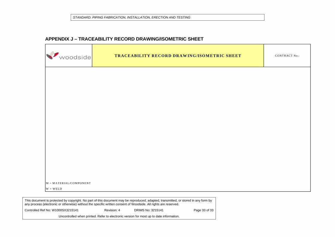
A typical format for a Tracability Record Sheet for piping and for Drawings/Isometrics is shown in Appendix I and Appendix J respectively. The Contractor may use his own format providing all information shown in Appendix I and/or Appendix J is included.
8. REFERENCES AS1627.4 Metal Finishing – Preparation and Pretreatment of Surfaces.
Part 4: Abrasive Blast Cleaning of Steel. AS 4458 Pressure equipment – Manufacture AS 4041 Pressure Piping
AS/NZ 4680 Hot Dip Galvanized (Zinc) Coatings on Fabricated Ferrous Articles
ANSI B31.3 Process Piping
DEP 61.38.10.10 Shop & Field Fabrication of Orifice Meter Runs
W1000SM001 Hydrostatic and Pneumatic Pressure Testing
W1000SM002 Protective Coatings
W1000SM3131997 Flange Bolting Standard
W1000SM3218383
Erection, Inspection, Maintenance and Preservation of Equipment
W1000SQ002 Certification, Marking and Inspection of Engineering Products
STANDARD: PIPING FABRICATION, INSTALLATION, ERECTION AND TESTING
This document is protected by copyright. No part of this document may be reproduced, adapted, transmitted, or stored in any form by any process (electronic or otherwise) without the specific written consent of Woodside. All rights are reserved.
Controlled Ref No: W1000SX3215141 Revision: 4 DRIMS No: 3215141 Page 20 of 33
Uncontrolled when printed. Refer to electronic version for most up to date information.
9. APPENDICES
APPENDIX
WELDING PROCEDURE QUALIFICATION TESTING REQUIREMENTS
A
FABRICATION TOLERANCES B
TYPICAL INSULATING FLANGE CONNECTION DETAILS
C
EXAMINATION GROUPS D
EXTENT OF TESTING AND INSPECTION E
INHIBITOR REQUIREMENTS FOR HYDROTEST WATER
F
INSPECTION AND TEST PLAN G
PIPING FIELD TEST REPORT H
TRACEABILITY RECORD SHEET I
TRACEABILITY RECORD DRAWING/ISOMETRIC SHEET
J

STANDARD: PIPING FABRICATION, INSTALLATION, ERECTION AND TESTING
This document is protected by copyright. No part of this document may be reproduced, adapted, transmitted, or stored in any form by any process (electronic or otherwise) without the specific written consent of Woodside. All rights are reserved.
Controlled Ref No: W1000SX3215141 Revision: 4 DRIMS No: 3215141 Page 21 of 33
Uncontrolled when printed. Refer to electronic version for most up to date information.
APPENDIX A - WELDING PROCEDURE QUALIFICATION TESTING REQUIREMENTS Test Method
Test details A106 Gr B / A105
CuNi A333 Gr 6 A333 Gr 3 304L/316L 22Cr Duplex 25Cr Superduplex
CrMo 6Mo Super-austenitic
Tensile ASME IX R R R R R R R R R Bends ASME IX R R R R R R R R R Charpy (Notes 1, 2, 3, 4)
ASME B31.3 . Locations: One set of 3 specimens to be taken from each of the following locations: Weld metal centreline, FL, FL+2, FL+5.
NR NR 27J average of 3 specimens, 21J minimum single specimen. Tested at -46°C
27J average of 3 specimens, 21J minimum single specimen. Tested at -101°C
Not required for lines above 101°C. For cryogenic lines, 0.38mm minimum lateral expansion required at -196°C.
40J average of 3 specimens, 31J minimum single specimen. Tested at –50°C
50J average of 3 specimens, 35J min single specimen. Tested at -46°C
NR Not required for lines above -101°C. For cryogenic lines, 0.38mm minimum lateral expansion required at MDT.
Macro X5 mag with photo
R R R R R R R R R
Hardness HV10 250 max (22 HRC)
NR 250 max (22 HRC)
320 max 250 max (22 HRC)
310 max (28 HRC)
330 max (32 HRC)
350 max NR
Corrosion
ASTM G48 Method A
NR NR NR NR NR 23°C for 24h. No pitting to be visible at x20 magnification Maximum weight loss 1.0 g/m2.
40°C for 24h. No pitting to be visible at x20 magnification Maximum weight loss 1.0 g/m2.
NR 40°C for 24h. No pitting to be visible at x20 magnification Maximum weight loss 4.0 g/m2.
Ferrite ASTM E562 NR NR NR NR 4 – 10% 30 – 70% 35 – 65% NR NR Micro 400X mag with
photo NR NR NR NR NR R Note 5 R Note 5 NR NR
Notes: R = required, NR = Not required
1 For subsize Charpy specimens, impact test temperature reduction shall be per ASME B31.3 Table 323.3.4. 2 Specimens shall be cut transverse to the weld, with the axis of the notch perpendicular to the pipe surface and so that one face of the specimen is substantially parallel
to and within 2mm of the top surface of the weld. 3 For wall thickness >25mm, an additional set of 3 specimens from the weld root (centreline) is to be tested. 4 Where more than one welding process is used in a single joint, the required impact tests shall be duplicated in the different regions of the joint.
STANDARD: PIPING FABRICATION, INSTALLATION, ERECTION AND TESTING
This document is protected by copyright. No part of this document may be reproduced, adapted, transmitted, or stored in any form by any process (electronic or otherwise) without the specific written consent of Woodside. All rights are reserved.
Controlled Ref No: W1000SX3215141 Revision: 4 DRIMS No: 3215141 Page 22 of 33
Uncontrolled when printed. Refer to electronic version for most up to date information.
5 Test samples shall comprise a cross section of the weld metal, heat affected zone and base metal. The micro-structure shall be suitably etched and examined at 400 X magnification and shall have grain boundary with no continuous precipitations and the inter-metallic phases, nitrides and carbides shall not in total exceed 0.5%

STANDARD: PIPING FABRICATION, INSTALLATION, ERECTION AND TESTING
This document is protected by copyright. No part of this document may be reproduced, adapted, transmitted, or stored in any form by any process (electronic or otherwise) without the specific written consent of Woodside. All rights are reserved.
Controlled Ref No: W1000SX3215141 Revision: 4 DRIMS No: 3215141 Page 23 of 33
Uncontrolled when printed. Refer to electronic version for most up to date information.
APPENDIX B - FABRICATION TOLERANCES
PFI Standard ED-3 Reaffirmed September 2000
FABRICATION TOLERANCES
METRIC CONVERSIONS
The conversion of quantities between of units involves a determination of the number of significant digits to be retained.
All conversions depend up on the intended precision of the original quantity and are rounded to the appropriate accuracy.
Pipe sizes together with applicable wall thickness are not shown with metric equivalents.
The SI (metric) values where included with the customary U.S. values in the Standard are the rounded equivalents of the U.S. values and are for reference only.
Metric units were derived utilizing the following factor:
Conversion Factor __________ ________
inches to 25.4
millimetre
1. Scope 1.1 This standard covers general pipe shop
fabrications tolerances for prefabricated piping assemblies.
2. Linear Tolerances
2.1 The tolerances of linear dimensions (intermediate or overall) apply to the face to face, face to end, and end to end measurements of fabricated straight pipe and headers; center to end or center to face of nozzles or other attachments; or center to face of bends; as illustrated on Fig. 1. These tolerances are not accumulative.
2.2 Linear tolerances on “A” are ± 1/8” (3.0
mm) for sizes 10” and under, ± 3/16” (5.0 mm) for sizes 12” through 24” and ± ¼” (6.0 mm) for sizes over 24” through 36”.
2.3 Linear tolerances on “A” for sizes over 36”
are subject to tolerances of ± ¼” (6.0 mm), increasing by plus or minus 1/16”
(2.0 mm) for each 12” in diameter over 36”.
2.4 Due to the cumulative effects of
tolerances on fittings or flanges, when joined without intervening pipe segments, deviations in excess of those specified in paragraphs 2.2 and 2.3 may occur.
3. Angularity and Rotation Tolerances
3.1 Angularity tolerance across the face of flanges, weld end preparation and on rotation of flanges are as stated on Fig. 1.
4. Close Tolerances
4.1 When closer tolerances than those given in paragraphs 2.2, 2.3 and 2.4 are absolutely necessary, they shall be subject to agreement between the Purchaser and Fabricator.

STANDARD: PIPING FABRICATION, INSTALLATION, ERECTION AND TESTING
This document is protected by copyright. No part of this document may be reproduced, adapted, transmitted, or stored in any form by any process (electronic or otherwise) without the specific written consent of Woodside. All rights are reserved.
Controlled Ref No: W1000SX3215141 Revision: 4 DRIMS No: 3215141 Page 24 of 33
Uncontrolled when printed. Refer to electronic version for most up to date information.
STANDARD: PIPING FABRICATION, INSTALLATION, ERECTION AND TESTING
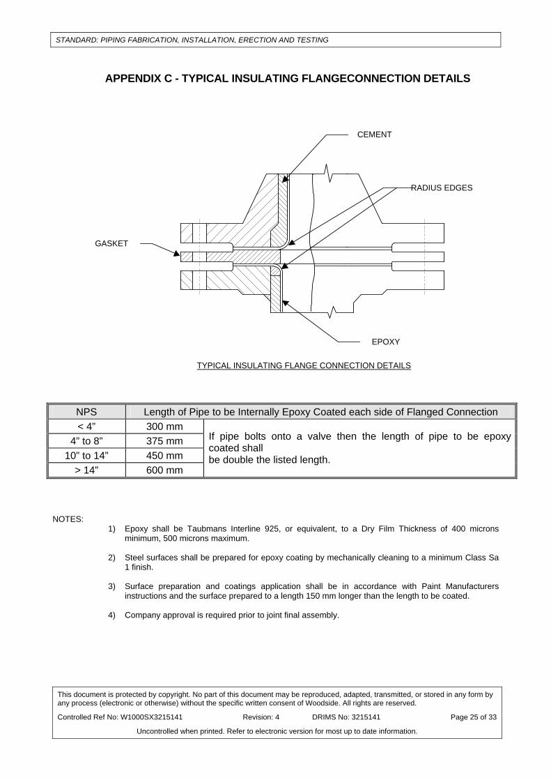
APPENDIX C - TYPICAL INSULATING FLANGECONNECTION DETAILS
GASKET
CEMENT
EPOXY
RADIUS EDGES
TYPICAL INSULATING FLANGE CONNECTION DETAILS
NPS Length of Pipe to be Internally Epoxy Coated each side of Flanged Connection < 4” 300 mm
4” to 8” 375 mm 10” to 14” 450 mm
> 14” 600 mm
If pipe bolts onto a valve then the length of pipe to be epoxy coated shall be double the listed length.
NOTES:
1) Epoxy shall be Taubmans Interline 925, or equivalent, to a Dry Film Thickness of 400 microns minimum, 500 microns maximum.
2) Steel surfaces shall be prepared for epoxy coating by mechanically cleaning to a minimum Class Sa 1 finish.
3) Surface preparation and coatings application shall be in accordance with Paint Manufacturers instructions and the surface prepared to a length 150 mm longer than the length to be coated.
4) Company approval is required prior to joint final assembly.
This document is protected by copyright. No part of this document may be reproduced, adapted, transmitted, or stored in any form by any process (electronic or otherwise) without the specific written consent of Woodside. All rights are reserved.
Controlled Ref No: W1000SX3215141 Revision: 4 DRIMS No: 3215141 Page 25 of 33
Uncontrolled when printed. Refer to electronic version for most up to date information.
STANDARD: PIPING FABRICATION, INSTALLATION, ERECTION AND TESTING
This document is protected by copyright. No part of this document may be reproduced, adapted, transmitted, or stored in any form by any process (electronic or otherwise) without the specific written consent of Woodside. All rights are reserved.
Controlled Ref No: W1000SX3215141 Revision: 4 DRIMS No: 3215141 Page 26 of 33
Uncontrolled when printed. Refer to electronic version for most up to date information.
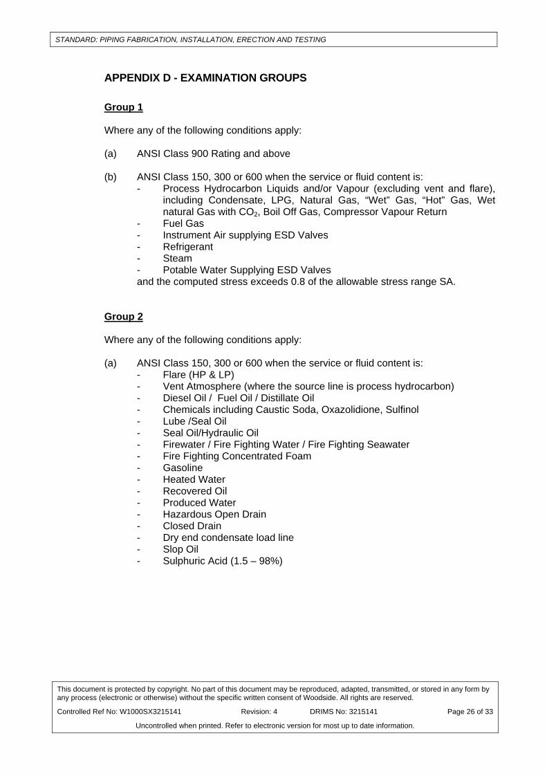
APPENDIX D - EXAMINATION GROUPS Group 1 Where any of the following conditions apply: (a) ANSI Class 900 Rating and above (b) ANSI Class 150, 300 or 600 when the service or fluid content is:
- Process Hydrocarbon Liquids and/or Vapour (excluding vent and flare), including Condensate, LPG, Natural Gas, “Wet” Gas, “Hot” Gas, Wet natural Gas with CO2, Boil Off Gas, Compressor Vapour Return
- Fuel Gas - Instrument Air supplying ESD Valves - Refrigerant - Steam - Potable Water Supplying ESD Valves and the computed stress exceeds 0.8 of the allowable stress range SA.
Group 2 Where any of the following conditions apply: (a) ANSI Class 150, 300 or 600 when the service or fluid content is:
- Flare (HP & LP) - Vent Atmosphere (where the source line is process hydrocarbon) - Diesel Oil / Fuel Oil / Distillate Oil - Chemicals including Caustic Soda, Oxazolidione, Sulfinol - Lube /Seal Oil - Seal Oil/Hydraulic Oil - Firewater / Fire Fighting Water / Fire Fighting Seawater - Fire Fighting Concentrated Foam - Gasoline - Heated Water - Recovered Oil - Produced Water - Hazardous Open Drain - Closed Drain - Dry end condensate load line - Slop Oil - Sulphuric Acid (1.5 – 98%)
STANDARD: PIPING FABRICATION, INSTALLATION, ERECTION AND TESTING
This document is protected by copyright. No part of this document may be reproduced, adapted, transmitted, or stored in any form by any process (electronic or otherwise) without the specific written consent of Woodside. All rights are reserved.
Controlled Ref No: W1000SX3215141 Revision: 4 DRIMS No: 3215141 Page 27 of 33
Uncontrolled when printed. Refer to electronic version for most up to date information.
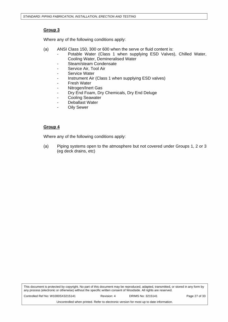
Group 3 Where any of the following conditions apply: (a) ANSI Class 150, 300 or 600 when the serve or fluid content is:
- Potable Water (Class 1 when supplying ESD Valves), Chilled Water, Cooling Water, Demineralised Water
- Steam/steam Condensate - Service Air, Tool Air - Service Water - Instrument Air (Class 1 when supplying ESD valves) - Fresh Water - Nitrogen/Inert Gas - Dry End Foam, Dry Chemicals, Dry End Deluge - Cooling Seawater - Deballast Water - Oily Sewer
Group 4 Where any of the following conditions apply: (a) Piping systems open to the atmosphere but not covered under Groups 1, 2 or 3
(eg deck drains, etc)

STANDARD: PIPING FABRICATION, INSTALLATION, ERECTION AND TESTING
This document is protected by copyright. No part of this document may be reproduced, adapted, transmitted, or stored in any form by any process (electronic or otherwise) without the specific written consent of Woodside. All rights are reserved.
Controlled Ref No: W1000SX3215141 Revision: 4 DRIMS No: 3215141 Page 28 of 33
Uncontrolled when printed. Refer to electronic version for most up to date information.
APPENDIX E - EXTENT OF TESTING AND INSPECTION
METHOD EXAMINATION GROUP (Note 1)
1 2 3 4 VISUAL 100% 100% 100% 100% MT (Note 2) (OR PT FOR NON-FERROMAGNETIC MATERIALS)
100% 100% Of branch
socket & attachment welds
10% Branch, socket & attachment welds Nil
RT (Note 3) (BUTT WELD) 100% 100% Coverage
on 1 in 10 welds 100% Coverage on
1 in 20 welds Nil
UT (Note 4) (BRANCH WELDS) 100% 0 0 0
ACCEPTANCE CRITERIA PER ANSI B31.3, TABLE 341.3.2A
Severe cyclic conditions
Severe cyclic conditions
Severe cyclic conditions
Severe cyclic conditions
HYDROTEST (Note 5, 7)
SHOP FAB SPOOLS Yes Yes Yes No
FIELD WELDS Yes (Note 6)
Yes (Note 6)
Yes (Note 6) No
MINIMUM DURATION ½ hour ½ hour ½ Hour N/A
RECORDS Yes Yes Yes N/A NOTES:
1 Examination groups are identified in Appendix C and are directly related to the extent of testing performed on each category of piping.
2 MT or PT of branch welds to be performed prior to attachment of compensating plate if applicable. 3 UT may be substituted for RT on carbon steel, low alloy steel, stainless, duplex and super duplex butt
welds, where there is access to both sides of the weld, and where approval by the TA is given. The UT operator and UT procedure shall be approved by the TA.
4 Not required where wall thickness for scanning surfaces are less than 10mm, and where branch
diameters are less than 125mm. Non-ferritic materials need not be examined.
5 Refer to piping isometrics for full hydrotest requirements. A hydrotest may only be waived with the written approval of the Materials and Inspection Group.
6 Hydrotest of field welds may be waived in accordance with section 345.2.6 and 345.2.3(c) of ASME B31.3. Where hydrotest is waived all field welds shall be subject to 100% RT and PT.
7 Refer to Appendix F for inhibitor requirements for hydrotest water.

STANDARD: PIPING FABRICATION, INSTALLATION, ERECTION AND TESTING
This document is protected by copyright. No part of this document may be reproduced, adapted, transmitted, or stored in any form by any process (electronic or otherwise) without the specific written consent of Woodside. All rights are reserved.
Controlled Ref No: W1000SX3215141 Revision: 4 DRIMS No: 3215141 Page 29 of 33
Uncontrolled when printed. Refer to electronic version for most up to date information.
APPENDIX F - REQUIREMENTS FOR HYDROTEST WATER
MATERIAL WATER QUALITY DURATION 1 COMMENTS
< 1 day
Corrosion inhibitor NOT REQUIRED
CARBON STEEL <200 PPM CHLORIDE
> 1 day
Corrosion inhibitor suitable for duration REQUIRED
AUSTENITIC, DUPLEX AND SUPERDUPLEX STAINLESS
STEEL Demineralised
<10PPM chloride all
As an ALTERNATIVE, potable type water with up to 200ppm chloride
may be used if it can be demonstrated that the component can be drained and thoroughly air
dried within 24 hours of completion of the hydrotest
COPPER BASED N/A all
Ensure water does NOT contain S
NON-METALLIC N/A all Corrosion inhibitor NOT required
Note: 1. Total contact time of test medium with component

STANDARD: PIPING FABRICATION, INSTALLATION, ERECTION AND TESTING
APPENDIX G – INSPECTION AND TEST PLAN TEST PLAN
P LA N N o.: IN SPE C T IO N A N D T E ST PL A N P A G E : O F
C ontractory N um ber: C ontractor:
D escrip tion : Subcontractor:
Item N o .: Location :
D escrip tion :
V erification /W itness
V endor P urchaser O ther
A ction Sign A ction Sign A ction Sign
A ction:
W W itness, M andatory H old Poin t R /A R eview and S ign D ocum entation
W /S W itness/Inspect a t R andom R R eview D ocum entation O nly
W /I W itness In itia l then at R andom
R eason for R evision D rawn C hecked R ev D ateStat.
Item N o./ O peration Stage N o.
M anufacturing or Inspection D escrip tionC ontractor
Inspection or T est P rocedure N o.
C ode/Standard/Specification
R eference
A cceptance C ritera
M D R R eport/R ecord T itle
This document is protected by copyright. No part of this document may be reproduced, adapted, transmitted, or stored in any form by any process (electronic or otherwise) without the specific written consent of Woodside. All rights are reserved.
Controlled Ref No: W1000SX3215141 Revision: 4 DRIMS No: 3215141 Page 30 of 33
Uncontrolled when printed. Refer to electronic version for most up to date information.

STANDARD: PIPING FABRICATION, INSTALLATION, ERECTION AND TESTING
APPENDIX H – PIPING FIELD TEST REPORT
C O N T R A C T N o .:P R IO R IT Y S Y S T E M N o .:
F L O W S H E E T S (R E F . D W G ): P IP IN G T E S T N o .:S H E E T N o .:T E S T P R E S S U R E : O FT E S T M E D IA :
L IN E N o . S I Z E IS O N o . F R O M T O IN S U . P A IN T R E M A R K S
S IG N E D B Y C O M P A N Y (P r io r to T e s t in g ) :
P IP IN G /M E C H A N IC A L E N G IN E E R N A M E D A T E
W E L D IN G IN S P E C T O R N A M E D A T E
T E S T W IT N E S S E D B Y : C O N T R A C T O R N A M E D A T E
C O M P A N Y N A M E D A T E
P I P I N G F I E L D T E S T R E P O R T
This document is protected bany process (electronic or otherwise) without the specific written consent of Woodside. All rights are reserved.
y copyright. No part of this document may be reproduced, adapted, transmitted, or stored in any form by
Controlled Ref No: W1000SX3215141 Revision: 4 DRIMS No: 3215141 Page 31 of 33
Uncontrolled when printed. Refer to electronic version for most up to date information.

STANDARD: PIPING FABRICATION, INSTALLATION, ERECTION AND TESTING
APPENDIX I – TRACEABILITY RECORD SHEET ITY RECORD SHEET
CONTRACT No.:
ISOM ETRIC No.: SPOOL:
INSPECTOR
CONTRACTOR COM PANY
COM M ENTS:
SIGNATURE NAM E DATE
SIGNATURE NAM E DATE
TRACEABILITY RECORD SHEET
PIPECLASS
UNIQUENUM BER DESCRIPTION OF ITEM
HEAT AND/ORTRACEABILITY NUM BERS
WELDERID
WELDING PROCEDURE
No.
CONSUM ABLE BATCH No.
CONTRACTORINSPECTOR
COMPANYINSPECTOR
This document is protected by copyright. No part of this document may be reproduced, adapted, transmitted, or stored in any form by any process (electronic or otherwise) without the specific written consent of Woodside. All rights are reserved.
Controlled Ref No: W1000SX3215141 Revision: 4 DRIMS No: 3215141 Page 32 of 33
Uncontrolled when printed. Refer to electronic version for most up to date information.
STANDARD: PIPING FABRICATION, INSTALLATION, ERECTION AND TESTING
This document is protected by copyright. No part of this document may be reproduced, adapted, transmitted, or stored in any form by any process (electronic or otherwise) without the specific written consent of Woodside. All rights are reserved.
TRACEABILITY RECORD DRAW ING/ISO M ETRIC SHEET CONTRACT No.:
M = M ATERIAL/COM PONENT
W = W ELD
Controlled Ref No: W1000SX3215141 Revision: 4 DRIMS No: 3215141 Page 33 of 33
Uncontrolled when printed. Refer to electronic version for most up to date information.
APPENDIX J – TRACEABILITY RECORD DRAWING/ISOMETRIC SHEET