physical solvent development for pre-combustion carbon capture · 2019-08-29 · 6. schematic of...
TRANSCRIPT

Physical Solvent Development for Pre-Combustion Carbon CaptureCO2 Capture Technology
Review Meeting 2019PI: Nicholas Siefert
TPL: David Hopkinson
August 27, 2019
2
Transformation Carbon Capture FWP: Task 6• Task 6 – Experimental testing of novel solvents for pre-combustion using
real syngas, $628K in EY19
• Partner: University of North Dakota’sEnergy & Environmental Research Center
• Synergistic Testing with TDA Research Inc.
• Focus of Presentation: • Overview of Advanced Solvent Capture Applications• Experimental testing at UND EERC• Conclusions & Future Work
https://undeerc.org/research/demonstration/gasification.html

3
Tailored markets• Pre-combustion CO2 Capture at IGCC-CCS • Adjust CO/H2 ratio for Coal & Biomass to Liquids • Generation of H2 from Reformed Natural Gas• Remove CO2 from syngas to produce Ammonia
Applications for Physical Solvents for Gas Separation
Image from: https://dakotagas.com/sites/CMS/files/images/home-hero/DGC-aerial-homepage.jpg

4
Problem:Commercially available physical solvents for CO2 /H2 separation operate at below room temperature. Hence, they incur a significant electrical cost to chill and can’t efficiently be regenerated using waste heat.
These solvents are hydrophilic and have high vapor pressure.
Selexol® (UOP) operates at 10oC Kemper County IGCC-CCS, MSRectisol® (Air Liquide) operates at -10oC Great Plains Synfuels Plant, ND
Solution:• Find new hydrophobic physical solvents that selectively absorb CO2 at
temperatures between 25oC and 100oC, and that can be regenerated using waste heat

5
Schematic of Baseline CO2 Capture
In Field and Brasington IGCC-CCS model, the
lean Selexol® enters the absorption column at
10oC, 52 bar
*Field and Brasington, Baseline Flowsheet Model for IGCC with Carbon Capture,Industrial & Engineering Chemistry Research 50(19) · August 2011
27oC, 52 bar25oC, 21 bar 20oC, 11 bar 11oC, 1.5 bar
13oC52 bar
• Requires cooler to maintain inlet solvent temperature at 10℃
• The temperature of the solvent is highest where you want it to be lowest, and lowest where you want it high
Problems with Traditional Approach
• Electricity is the sole source of work rather than waste heat
• No pressure recovery (unlike in RO Desalination plants)

6
Schematic of Advanced CO2 Capture
Projective Objective: Develop a process and a physicalsolvent that can operate at above room temperature cantake advantage of waste heat at the IGCC power plant
*Field and Brasington, Baseline Flowsheet Model for IGCC with Carbon Capture,Industrial & Engineering Chemistry Research 50(19) · August 2011
Goal: Reduce by >35%the overall electricityconsumption of the CO2Capture and Compressionprocess at a 550 MWIGCC-CCS Power Plant• Baseline electricity
consumption = 55 MW
7
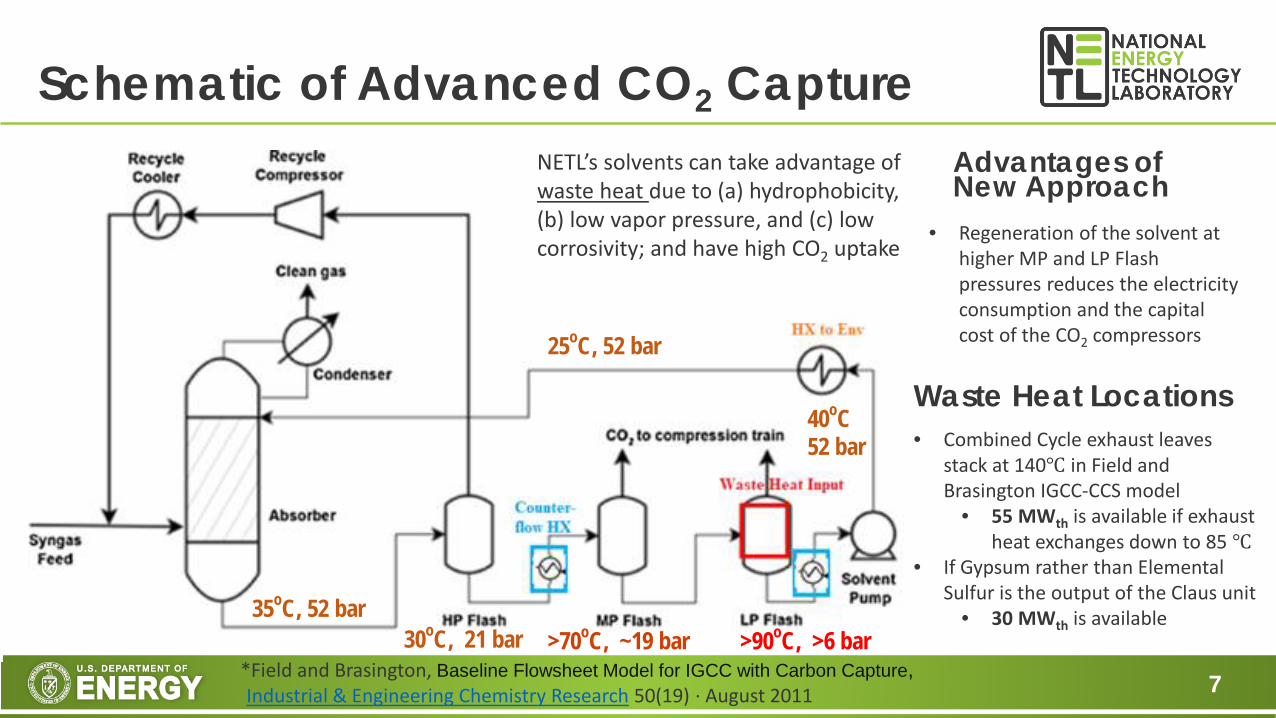
Schematic of Advanced CO2 Capture
*Field and Brasington, Baseline Flowsheet Model for IGCC with Carbon Capture,Industrial & Engineering Chemistry Research 50(19) · August 2011
35oC, 52 bar30oC, 21 bar >70oC, ~19 bar >90oC, >6 bar
25oC, 52 bar
40oC52 bar
• Regeneration of the solvent at higher MP and LP Flash pressures reduces the electricity consumption and the capital cost of the CO2 compressors
Advantages of New Approach
NETL’s solvents can take advantage of waste heat due to (a) hydrophobicity, (b) low vapor pressure, and (c) low corrosivity; and have high CO2 uptake
Waste Heat Locations• Combined Cycle exhaust leaves
stack at 140℃ in Field and Brasington IGCC-CCS model
• 55 MWth is available if exhaust heat exchanges down to 85 ℃
• If Gypsum rather than Elemental Sulfur is the output of the Claus unit
• 30 MWth is available

8
• 4 Solvents were experimentally tested in a pre-combustion• 2 Commercially-available solvents: Selexol Surrogate and Tributyl Phosphate (TBP)• 2 NETL chosen solvents: PEG-PDMS-3 (Synthesized by R. Thompson) and CASSH-1
(Computationally Screen by W. Shi)
• All 4 physical solvents were tested under real syngas generated at a UND EERC fluidized bed gasifier with fixed inlet syngas conditions:
• Total Pressure = 48 bar• Temperature = 40℃• Composition ≈ 50% CO2, 18% H2, 30% N2, 1.4% CH4, 0.4% H2S, 0.2% H2O
• A Sour Water-Gas-Shift Catalyst by TDA Inc. was used to convert CO to CO2+H2
Overview of Real Syngas Testing
https://netl.doe.gov/sites/default/files/netl-file/N-Siefert-NETL-High-Performance-Physical-Solvent.pdfhttps://netl.doe.gov/sites/default/files/netl-file/W-Shi-NETL-Solvent-Data-Mining.pdf

9
Absorber
Facility Overview
Flash Storage Tank
https://undeerc.org/research/demonstration/gasification.html

10
Results for CO2 Uptake and CO2/H2 Selectivity
>90% Capture Cases UnitsSelexol
Surrogate PEG-PDMS-3 CASSH-1 TBPCO2 Uptake (10℃) [mol/L·bar] 0.18 0.20 0.27 0.17CO2 Uptake (25℃) [mol/L·bar] 0.15 0.18 0.21 0.18CO2 Uptake (40℃) [mol/L·bar] NA 0.19 0.21 0.21
CO2/H2 Selectivity (10℃) [-] 20 19 25 11CO2/H2 Selectivity (25℃) [-] 17 17 20 13CO2/H2 Selectivity (40℃) [-] NA 16 19 13
Calculation via Desorption Method
Uptake CO2 [mol/L·bar] = Flow Rate of CO2 leaving the desorption flash tank (mol/hr) divided by the partial pressure of CO2 in the inlet syngas (bar) and also divided by the flow rate of the lean solvent entering the top of the absorption column (L/hr)
Selexol surrogate from Univar USA (Bunola, PA)

11
Comparison with Aspen Plus Simulations: Selexol 10℃
Note Selexol enters at 10℃and exits at 30℃ in the exp and simulation
Mixed Gas Simulation
(Based on UOP data)
Experimental(Selexol Surrogate
at UND EERC)AspenPlus Desorption
CO2 uptake 10℃ [mol/L·bar] 0.11 0.18H2 Uptake 10℃ [mol/L·bar] 0.002 0.009N2 Uptake 10℃ [mol/L·bar] 0.003 0.014H2S Uptake 10℃ [mol/L·bar] 0.18 0.17
CO2 / H2 Selectivity 10℃ [-] 55 20H2S / CO2 Selectivity 10℃ [-] 1.7 1.0CO2 / N2 Selectivity 10℃ [-] 33 13
*Field and Brasington, Baseline Flowsheet Model for IGCC with Carbon Capture,Industrial & Engineering Chemistry Research 50(19) · August 2011

12
• CASSH-1 and PEG-PDMS-3 at 40oC are out performing Selexol at 10oC• Both solvents have great potential for reducing electricity consumption associated
with CO2 Capture from syngas applications
• CO2 uptake values were higher than expected from simulations and the CO2/H2 selectivity values were much lower than expected from simulations
• We will be looking to collect long-term data from both the fluidized bed gasifier at UND EERC and the entrained flow gasifier at U.Ky CAER
• Develop processes & solvents compatible with modular-scale gasification
Conclusions & Future Work

13
Acknowledgements• NETL/R&IC Solvents Teams
• Robert Thompson • Jeffrey Culp • Lei Hong • Wei Shi • Surya Tiwari• Jan Steckel• Kevin Resnik • Nicholas Siefert (PI)• David Hopkinson (TPL)
• UND EERC Staff• Michael Swanson• Joshua Stanislowski• Scott Klara
• NETL & DOE/FE Project Management• Lynn Brickett (HQ)• John Litynski (HQ)• Timothy Fout (TM)
• NETL/R&IC Management• Randall Gemmen• David Berry • David Alman