appendix b: carbon dioxide capture … library/research/coal/carbon capture... · development and...
TRANSCRIPT

APPENDIX B: CARBON DIOXIDE CAPTURE TECHNOLOGY SHEETS
POST-COMBUSTION SOLVENTS
B-202
POST
-CO
MBU
STIO
N S
OLV
ENTS
U.S. DEPARTMENT Of ENERGY
ADVANCED CARBON DIOXIDE CAPTURE R&D PROGRAM: TECHNOLOGY UPDATE, MAY 2013

DEVELOPMENT AND DEMONSTRATION Of WASTE HEAT INTEGRATION WITH SOLVENT PROCESS fOR MORE EffICIENT CO2 REMOVAL fROM COAL-fIRED fLUE GAS
primary project goals
Southern Company Services is developing viable heat integration methods for the capture of carbon dioxide (CO2) produced from pulverized coal (PC) combustion. The project will quantify energy-efficiency improvements to the CO2 capture process by utilizing a waste heat recovery technology, High-Efficiency System (HES).
technical goals
• Reduction of the amount of extraction steam required for sensible heat load in the solvent regeneration system by the providing of process stream heating through waste heat stream.
• Heating of boiler feed water through waste heat to reduce extraction steam demands on the low-pressure (LP) turbine.
• Increasing LP steam available for power generation or CO2 regeneration.
technical content
Southern Company Services is developing viable heat integration methods for the capture and sequestration of CO2 produced from PC combustion. A waste heat recovery (HES) tech-nology is being integrated into an existing 25-MW pilot amine-based CO2 capture process to evaluate improvements in the energy performance of the integrated PC plant and CO2 capture process. The HES is a heat exchanger that extracts waste heat from flue gas exiting the power plant’s air-preheater and makes that heat available for use elsewhere in the power plant and CO2 recovery plant.
technology maturity:
Pilot-Scale, Actual flue Gas Slipstream
project focus:
Waste Heat Integration
participant:
Southern Company
project number:
fE0007525
NETL project manager:
Bruce [email protected]
principal investigator:
Nick IrvinSouthern [email protected]
partners:
Mitsubishi Heavy Industries
performance period:
10/1/11 – 3/31/16
B-203
POST-C
OM
BUSTIO
N SO
LVENTS
APPENDIX B: CARBON DIOXIDE CAPTURE TECHNOLOGY SHEETS
NATIONAL ENERGY TECHNOLOGY LABORATORY

figure 1: Heat Integration of Power Plant and CCS, Including HES
technology advantages
• The HES provides the efficient use of traditionally wasted heat in coal-fired flue gas and captured CO2.
• Water usage and parasitic energy loss in carbon capture and storage (CCS) is reduced by the technology.
• The HES accommodates more efficient removal of sulfur trioxide (SO3) and heavy metals in the electrostatic precipitator by reducing the flue gas temperature and resistivity of fly ash.
• This technology could prove to be a vital method of controlling water usage in a flue gas desulfurization (FGD) due to lower flue gas inlet temperature.
R&D challenges
• This project represents an advanced integration of waste heat in an existing steam cycle and CO2 capture plant; thus, control schemes need to be developed/proven that will maintain a proper heat balance in the steam cycle and carbon capture plant.
• Lowering flue gas temperature after the air-preheater can be problematic due to metal corrosion potential as a result of acid gas condensation; developing specific operating parameters and controls to manage the threat will be a special challenge.
results to date/accomplishments
• A front-end engineering design (FEED) study was completed and a target cost estimate for construction was assembled.
• The techno-economic analysis was competed.
• All equipment was sized and priced.
• The controls architecture was developed.
• A test plan for the operational period was finalized.
• The continuation application was submitted to the U.S. Department of Energy (DOE).
B-204
POST
-CO
MBU
STIO
N S
OLV
ENTS
U.S. DEPARTMENT Of ENERGY
ADVANCED CARBON DIOXIDE CAPTURE R&D PROGRAM: TECHNOLOGY UPDATE, MAY 2013

next steps
Engineering, Procurement, and Construction (EPC).
available reports/technical papers/presentations
N/A
B-205
POST-C
OM
BUSTIO
N SO
LVENTS
APPENDIX B: CARBON DIOXIDE CAPTURE TECHNOLOGY SHEETS
NATIONAL ENERGY TECHNOLOGY LABORATORY

APPLICATION Of A HEAT-INTEGRATED POST-COMBUSTION CO2 CAPTURE SYSTEM WITH HITACHI ADVANCED SOLVENT INTO EXISTING COAL-fIRED POWER PLANT
primary project goals
The University of Kentucky is using an innovative heat-integration method that would utilize waste heat from a carbon capture system using the Hitachi advanced solvent while improving steam turbine efficiency. The proposed process also implements a process con-cept (working with the heat integration method) that increases solvent capacity and capture rate in the carbon dioxide (CO2) scrubber.
Develop a process using a two-stage stripping concept combined with an innovative heat in-tegration method that utilizes waste heat to reduce costs through use of an improved power plant cooling tower by testing the process in a 0.7-MWe slipstream pilot-scale system.
technical goals
• Demonstrate the University of Kentucky Center for Applied Energy Research (UK-CAER) high-efficiency heat-integrated process.
• Demonstrate the UK-CAER process using the Hitachi advanced solvent.
• Gather data on solvent degradation and water management.
• Gather data on material corrosion and identify appropriate materials for a scale-up plant.
technical content
The objective of this project is to pilot-test a novel heat-integration scheme utilizing waste heat from the CO2 capture system (CCS) to improve the plant and CCS system efficiency, which will meet the U.S. Department of Energy (DOE) performance and cost targets of 90 percent CO2 capture, 95 percent CO2 purity, and an increase in the cost of electricity (COE) of no more than 35 percent. To achieve this, the proposed capture system uses a two-stage stripper configuration where the second stage is designed as an air stripper to reduce the carbon loading in the lean solvent with CO2-laden air feeding into the boiler as combustion air and an optimized two-stage cooling tower concept to reduce the condenser temperature, thereby improving the turbine efficiency. The project will also involve determining the per-formance of monoethanolamine (MEA) and the Hitachi advanced solvent in the proposed capture system, identify appropriate materials and solvent pollution control technologies necessary for a 550-MW commercial-scale carbon capture plant, demonstrate the capabil-ity of integrating waste heat from the carbon capture platform with the balance-of-plant to improve the overall plant efficiency, and collect the necessary information/data to provide a full techno-economic and environmental health and safety (EH&S) analysis.
technology maturity:
Pilot-Scale, Actual flue Gas Slipstream
project focus:
Slipstream Demonstration Using the Hitachi Advanced Solvent
participant:
University of Kentucky
project number:
fE0007395
NETL project manager:
Jose [email protected]
principal investigator:
Kunlei LiuUniversity of [email protected]
partners:
Hitachi Power Systems AmericaElectric Power Research InstituteSmith Management Group
performance period:
10/1/11 – 1/31/16
B-206
POST
-CO
MBU
STIO
N S
OLV
ENTS
U.S. DEPARTMENT Of ENERGY
ADVANCED CARBON DIOXIDE CAPTURE R&D PROGRAM: TECHNOLOGY UPDATE, MAY 2013

The project will involve the design, fabrication, installation, testing, and analyses of a slipstream facility located at LKE’s E.W. Brown Generating Station to demonstrate an innovative carbon capture system that utilizes heat integration with the main power plant. The design, start-up, and baseline of the pilot system will be performed with a generic 30 wt% MEA solvent to obtain data for direct comparison with the National Energy Technology Laboratory (NETL) reference case and Hitachi’s proprietary solvent H3-1 that will be tested in the project. Parametric test campaigns, system transient dynamic studies, and long-term continuous verification tests of the heat-integration process and for each of the solvents will be conducted. The series of transient tests will quantify the ability of the carbon capture system to follow load demand, flue gas conditions, and indi-vidual component operation. Concurrent with the continuous verification runs, corrosion evaluation and solvent degradation (liquid and gaseous emissions) studies will be conducted. The potential heat integra-tion, solvent and water management, and CO2 capture system stability and operability will be the main focus points.
TABLE 1: PROCESS PARAMETERSUnits Current R&D Value Target R&D Value
Pure Solvent
Molecular Weight mol-1 Confidential
Normal Boiling Point °C Confidential
Normal Freezing Point °C -
Vapor Pressure @ 15°C bar -
Manufacturing Cost for Solvent $/kg Confidential
Working Solution
Concentration kg/kg Confidential
Specific Gravity (15°C/15°C) - 0.98
Specific Heat Capacity @ STP kJ/kg-K 0.92
Viscosity @ STP cP 7.0
Absorption
Pressure bar ≈ 1 ≈ 1
Temperature °C 40-50
Equilibrium CO2 Loading mol/mol -
Heat of Absorption kJ/mol CO2 -
Solution Viscosity cP 7.7
Desorption
Pressure bar ≈2 3
Temperature °C 110-120
Equilibrium CO2 Loading mol/mol -
Heat of Desorption kJ/mol CO2 -
figure 1: Proposed Slipstream Carbon Capture System
B-207
POST-C
OM
BUSTIO
N SO
LVENTS
APPENDIX B: CARBON DIOXIDE CAPTURE TECHNOLOGY SHEETS
NATIONAL ENERGY TECHNOLOGY LABORATORY

TABLE 1: PROCESS PARAMETERSUnits Current R&D Value Target R&D Value
Proposed Module Design (for equipment developers)
Flue Gas Flowrate kg/hr
CO2 Recovery, Purity, and Pressure % / % / bar
Adsorber Pressure Drop bar
Estimated Absorber/Stripper Cost of Manufacturing and Installation
$
kg/hr
Definitions:
STP – Standard Temperature and Pressure (15°C, 1 atm).
Pure Solvent – Chemical agent(s), working alone or as a component of a working solution, responsible for enhanced CO2 absorp-tion (e.g., the amine MEA in an aqueous solution).
Manufacturing Cost for Solvent – “Current” is market price of chemical, if applicable; “Target” is estimated manufacturing cost for new solvents, or the estimated cost of bulk manufacturing for existing solvents.
Working Solution – The solute-free (i.e., CO2-free) liquid solution used as the working solvent in the absorption/desorption pro-cess (e.g., the liquid mixture of MEA and water).
Absorption – The conditions of interest for absorption are those that prevail at maximum solvent loading, which typically occurs at the bottom of the absorption column. These may be assumed to be 1 atm total flue-gas pressure (corresponding to a CO2 partial pressure of 0.13 bar) and 40°C; however, measured data at other conditions are preferable to estimated data.
Desorption – The conditions of interest for desorption are those that prevail at minimum solvent loading, which typically occurs at the bottom of the desorption column. Operating pressure and temperature for the desorber/stripper are process-dependent (e.g., an MEA-based absorption system has a typical CO2 partial pressure of 1.8 bar and a reboiler temperature of 120°C). Measured data at other conditions are preferable to estimated data.
Pressure – The pressure of CO2 in equilibrium with the solution. If the vapor phase is pure CO2, this is the total pressure; if it is a mixture of gases, this is the partial pressure of CO2. Note that for a typical PC power plant, the total pressure of the flue gas is about 1 atm and the concentration of CO2 is about 13.2 percent. Therefore, the partial pressure of CO2 is roughly 0.132 atm or 0.130 bar.
Concentration – Mass fraction of pure solvent in working solution.
Loading – The basis for CO2 loadings is moles of pure solvent.
Estimated Cost – Basis is kg/hr of CO2 in CO2-rich product gas; assuming targets are met.
Other Parameter Descriptions:
Chemical Solvent Mechanism – The absorption reactions for the amine-based CO2 capture system can be broken into two reac-tions, as given below. The absorption of CO2 by primary and secondary amines (SC1) is mainly dictated by the formation of carbamates. The reaction of CO2 with tertiary amines (SC2) results in the formation of a bicarbonate.
Absorption Reactions:
SC1 + CO2 → SC1-COO- + H+
SC2 + H2O + CO2 → SC2-HCO3- + H+
In the stripper, the reverse reactions occur with energy input to drive the endothermic reaction and produce free CO2.
B-208
POST
-CO
MBU
STIO
N S
OLV
ENTS
U.S. DEPARTMENT Of ENERGY
ADVANCED CARBON DIOXIDE CAPTURE R&D PROGRAM: TECHNOLOGY UPDATE, MAY 2013

The reaction rate constant for primary and secondary amine species can vary, but is generally on the order of 103. The reaction with tertiary amines to directly form bicarbonate is much slower (10x less). A third possible reaction to form bicarbonate directly from hydroxide present in solution can generally be excluded from consideration despite the fast rate constant (104) because the hydroxide concentration is limited by the base dissociation constant in 30 wt% MEA (<1x10⁻⁴).
The heat of desorption (dictated by chemical bond enthalpy, gas dissolution, and non-ideal mixing) represents a large portion of the energy input required to drive the endothermic reaction and produce free CO2 in the stripper. Considering only the chemical reaction component (bulk contribution at stripping conditions), the lowest energy solvent is represented by the bicarbonate reac-tion (27 kJ/mol), while the carbamate reaction is much higher at approximately 60 to 70 kJ/mol. The Hitachi advanced solvent is optimized to minimize heat of regeneration, yielding an overall energy requirement that is ≈36 percent lower than a baseline MEA solvent for a conventional process.
The rate of CO2 capture is a function of the overall mass transfer coefficient, interfacial area, and the mean difference in concen-tration of CO2 in the flue gas and amine solvent phases. The rate is enhanced if the driving force (mean flue gas CO2 concentration – mean CO2 concentration in solvent) is also increased. The size of absorber needed to capture a given quantity of CO2 is reduced because the solvent has higher rates of CO2 capture compared to MEA (mass transfer coefficient), and also due to the larger con-centration gradient due to the air stripping process enhancements.
Solvent Contaminant Resistance – Exposure to sulfur dioxide (SO2), halogen, nitrogen oxide (NOx), and trace metals that are present in the feed flue gas stream can cause the solvent to degrade with time.
Solvent Foaming Tendency – The Hitachi solvent has a low tendency for foaming in the scrubber.
Flue Gas Pretreatment Requirements – After passing through the power plant’s SO2 scrubber, flue gas enters a direct water con-tactor to reduce the CO2 absorber operating temperature and remove excess water. Following this, the flue gas enters a counter-flow, pre-treatment tower using a dilute caustic solution for the removal of the final SO2 and other gaseous contaminants before entering the CO2 scrubber.
Solvent Make-Up Requirements – Compared to 30 wt% MEA, the Hitachi solvent has low degradation rate and requires approxi-mately 15 percent of MEA make-up rate.
Waste Streams Generated – Solid waste (ash, sulfur, and nitric compounds) generated after the flue gas pre-treatment tower and sludge waste from the amine reclaimer will be removed.
Process Design Concept – As presented in the flowsheet/block flow diagram.
Proposed Module Design – Unless noted, flue gas pressure, temperature, and composition leaving the flue gas desulfurization (FGD) unit (wet basis) should be assumed as:
Pressure 14.7 psia
Temperature 135°F
Composition
vol percentCO2 13.17
H2O 17.25
N2 66.44
O2 2.34
Ar 0.80
ppmvSOx 42
NOx 74
B-209
POST-C
OM
BUSTIO
N SO
LVENTS
APPENDIX B: CARBON DIOXIDE CAPTURE TECHNOLOGY SHEETS
NATIONAL ENERGY TECHNOLOGY LABORATORY

technology advantages
• The two-stage stripping unit, including the deployment of an air-based secondary stripper, will regenerate an exceptionally CO2-lean solvent, increasing the rate of CO2 absorption.
• Cooling water temperature with the heat-integrated cooling tower can be decreased by more than 2°C compared to conven-tional evaporative cooling towers, leading to improved steam turbine and power plant efficiency and lower levelized cost of electricity (LCOE).
• The solvent recovery column at the outlet of the gas stream leaving the CO2 absorber uses water from the in-duct cooler to neutralize and recover solvent vapor in this stream.
• The primary CO2 stripper can be operated at approximately 3 bars in order to maximize the energy benefit while minimizing system capital and solvent degradation, which could lead to low compressor capital and operating costs.
• The H3-1 advanced solvent used in this system has (1) a higher mass-transfer flux, (2) a higher net cycle carbon capacity, (3) less energy demand for CO2 stripping, and (4) lower corrosion rates than a 30 wt% MEA solution.
• H3-1 is also less corrosive than MEA and has 89 percent lower thermal and oxidative degradation rates compared to MEA, leading to low capital costs and low solvent make-up costs.
R&D challenges
• Solvent air stripping has been demonstrated at the bench scale, but will need to be demonstrated at the slipstream scale.
• The application of a liquid desiccant for the integrated cooling system has been demonstrated for HVAC applications, but will need to be demonstrated for this application.
• Solvent oxidation in the air stripper due to high oxygen content (approximately 12%) must be determined.
results to date/accomplishments
• Results from a preliminary techno-economic analysis indicated significant reduction (≈56%) in the incremental LCOE over a subcritical power plant without CO2 capture versus 80 percent incremental LCOE for a plant with MEA CO2 capture system.
• Compared to the Case 10 of the bituminous coal baseline using the conventional Fluor Econamine FG+ technology using MEA as the solvent, the capital costs of the coal power plant using the UK-CAER technology with the MEA solvent were lowered by 10 percent. Compared to the UK-CAER/MEA case, the capital costs of the plant with the UK-CAER/H3-1 tech-nology were further lowered by 6.7 percent.
• It was estimated from process modeling that the UK-CAER solvent requires ≈36.8 percent lower thermal energy for regen-eration compared to the DOE/NETL Reference Case10.
• Laboratory corrosion tests indicated that H3-1 had a lower corrosion rate compared to MEA, and so lower-cost materials of construction (carbon steel) could be used instead of stainless steel, lowering the plant capital costs.
• A preliminary EH&S assessment indicated minimal or insignificant levels of emissions of solvent degradation byproducts, as well as total air emissions from the proposed 0.7 MWe pilot at the E.W.Brown station.
next steps
• A 0.7-MWe slipstream pilot would be commissioned at the E.W.Brown Generating Station by May 2014.
• Parametric pilot-scale tests using 30 w/w percent MEA and H3-1 would be completed by November 2014 and November 2015, respectively.
available reports/technical papers/presentations
N/A
B-210
POST
-CO
MBU
STIO
N S
OLV
ENTS
U.S. DEPARTMENT Of ENERGY
ADVANCED CARBON DIOXIDE CAPTURE R&D PROGRAM: TECHNOLOGY UPDATE, MAY 2013

SLIPSTREAM PILOT-SCALE DEMONSTRATION Of A NOVEL AMINE-BASED POST-COMBUSTION PROCESS TECHNOLOGY fOR CO2 CAPTURE fROM COAL-fIRED POWER PLANT fLUE GAS
primary project goals
Linde is refining a post-combustion capture technology incorporating BASF’s novel amine-based process to reduce regeneration energy requirements by designing, building, and operating a 1-MWe equivalent slipstream pilot plant at the National Carbon Capture Center (NCCC).
technical goals
• Complete techno-economic assessment of a 550-MWe power plant integrated with the Linde-BASF post-combustion capture plant incorporating BASF’s OASE® blue aque-ous amine-based solvent to illustrate the benefits.
• Develop and optimize a basic design package for a 1-MWe equivalent pilot plant.
• Build and operate the 1-MWe pilot plant at a coal-fired power plant host site providing the flue gas as a slipstream.
• Implement parametric tests to demonstrate the achievement of target performance using data analysis.
• Implement long duration testing to demonstrate solvent stability and obtain critical data for scale-up.
technical content
Linde and partners are designing, building, and operating a 1-MWe pilot plant at NCCC. The technology aims to reduce the regeneration energy requirements using novel solvents that are stable under coal-fired power plant feed gas conditions. BASF’s OASE® blue technology has been developed to address the key drawbacks in the large-scale applica-tion of monoethanolamine (MEA) for flue gas carbon capture, including: (1) high specific energy for regeneration, (2) lack of stability toward thermal and oxidative degradation, (3) increased corrosiveness with increased carbon dioxide (CO2) loading, and (4) lack of tolerance to impurities from coal combustion products. The specific proprietary solvent has been selected by: (1) screening approximately 400 chemical substances using vapor-liquid equilibrium measurements to determine approximate cyclic capacities, (2) laboratory measurements of the key thermodynamic and kinetic properties of the 70 screened candi-dates and their mixtures to identify approximately 15 targets, (3) testing of the targets to determine optimum circulation rate and specific energy consumption in a laboratory-scale mini-plant to identify the leading candidates, and (4) pilot testing of three candidates with real power plant flue gas to identify the optimum solvent for the flue gas application. The
technology maturity:
Pilot-Scale, Actual flue Gas Slipstream
project focus:
Slipstream Novel Amine-Based Post-Combustion Process
participant:
Linde
project number:
fE0007453
NETL project manager:
Andrew [email protected]
principal investigator:
Krish [email protected]
partners:
Selas fluid Processing CorporationBASf SELinde Engineering Dresden GmbHEPRI
performance period:
12/1/11 – 11/30/15
B-211
POST-C
OM
BUSTIO
N SO
LVENTS
APPENDIX B: CARBON DIOXIDE CAPTURE TECHNOLOGY SHEETS
NATIONAL ENERGY TECHNOLOGY LABORATORY

CO2 regeneration from the solvent is carried out by using low-pressure steam, typically from the power plant steam cycle. Testing using a 0.45-MWe pilot plant utilizing lignite-fired power plant flue gas has shown that the OASE blue solvent is stable and little degradation was observed over 5,000 hours, whereas the reference MEA solvent started to degrade appreciably under same condi-tions after 2,000 hours.
Linde’s post-combustion CO2 capture process using BASF OASE blue solvent has several distinct characteristics. Firstly, the direct-contact cooler, CO2 absorber, and water wash are integrated into a single column with high-performance structured packing for increased capacity (smaller absorber diameter) and an advanced material of construction to minimize capital costs. Secondly, the absorber also has an interstage solvent cooler operating on gravity flow, eliminating the capital and operating expenses of a solvent pump. The flue gas blower is located downstream of the absorber to minimize its size (due to the lesser volume of flue gas handled by the blower). Further, the stripping column can be operated at higher pressures (up to 3.6 atm) than that of a MEA stripper, lowering compression costs. Finally, optional process heat integration allows steam raised by heat exchange with flue gas before the flue gas desulfurization (FGD) unit to be used at an intermediate point in the desorber, and the use of back-pressure steam turbines allows the recovery of part of the energy of the intermediate-pressure (IP), low-pressure (LP) crossover steam.
figure 1: Linde-BASf Post-Combustion Capture Plant
TABLE 1: PROCESS PARAMETERS BASED ON TECHNO-ECONOMIC ASSESSMENT OF A 550-MW PLANT (SEE REFERENCE)
Units Current R&D Value Target R&D Value
Pure Solvent
Molecular Weight mol-1 Proprietary
Normal Boiling Point °C
Normal Freezing Point °C
Vapor Pressure @ 15°C bar
Manufacturing Cost for Solvent $/kg
B-212
POST
-CO
MBU
STIO
N S
OLV
ENTS
U.S. DEPARTMENT Of ENERGY
ADVANCED CARBON DIOXIDE CAPTURE R&D PROGRAM: TECHNOLOGY UPDATE, MAY 2013

TABLE 1: PROCESS PARAMETERS BASED ON TECHNO-ECONOMIC ASSESSMENT OF A 550-MW PLANT (SEE REFERENCE)
Units Current R&D Value Target R&D Value
Working Solution
Concentration kg/kg
Specific Gravity (15°C/15°C) -
Specific Heat Capacity @ STP kJ/kg-K
Viscosity @ STP cP
Absorption
Pressure bar ≈1 atm ≈1 atm
Temperature °C 30-70 30-60
Equilibrium CO2 Loading mol/mol
Heat of Absorption kJ/mol CO2
Solution Viscosity cP
Desorption
Pressure bar 1.6 to 2.5 1.6 to 3.5
Temperature °C Proprietary
Equilibrium CO2 Loading mol/mol
Heat of Desorption kJ/mol CO2
Proposed Module Design (for equipment developers)
Flue Gas Flowrate kg/hr
CO2 Recovery, Purity, and Pressure % / % / bar
Adsorber Pressure Drop bar
Estimated Absorber/Stripper Cost of Manufacturing and Installation
$
kg/hr
Definitions:
STP – Standard Temperature and Pressure (15°C, 1 atm).
Pure Solvent – Chemical agent(s), working alone or as a component of a working solution, responsible for enhanced CO2 absorp-tion (e.g., the amine MEA in an aqueous solution).
Manufacturing Cost for Solvent – “Current” is market price of chemical, if applicable; “Target” is estimated manufacturing cost for new solvents, or the estimated cost of bulk manufacturing for existing solvents.
Working Solution – The solute-free (i.e., CO2-free) liquid solution used as the working solvent in the absorption/desorption pro-cess (e.g., the liquid mixture of MEA and water).
Absorption – The conditions of interest for absorption are those that prevail at maximum solvent loading, which typically occurs at the bottom of the absorption column. These may be assumed to be 1 atm total flue-gas pressure (corresponding to a CO2 partial pressure of 0.13 bar) and 40°C; however, measured data at other conditions are preferable to estimated data.
Desorption – The conditions of interest for desorption are those that prevail at minimum solvent loading, which typically occurs at the bottom of the desorption column. Operating pressure and temperature for the desorber/stripper are process-dependent (e.g., an MEA-based absorption system has a typical CO2 partial pressure of 1.8 bar and a reboiler temperature of 120°C). Measured data at other conditions are preferable to estimated data.
B-213
POST-C
OM
BUSTIO
N SO
LVENTS
APPENDIX B: CARBON DIOXIDE CAPTURE TECHNOLOGY SHEETS
NATIONAL ENERGY TECHNOLOGY LABORATORY

Pressure – The pressure of CO2 in equilibrium with the solution. If the vapor phase is pure CO2, this is the total pressure; if it is a mixture of gases, this is the partial pressure of CO2. Note that for a typical PC power plant, the total pressure of the flue gas is about 1 atm and the concentration of CO2 is about 13.2 percent. Therefore, the partial pressure of CO2 is roughly 0.132 atm or 0.130 bar.
Concentration – Mass fraction of pure solvent in working solution.
Loading – The basis for CO2 loadings is moles of pure solvent.
Estimated Cost – Basis is kg/hr of CO2 in CO2-rich product gas; assuming targets are met.
Other Parameter Descriptions:
Flue Gas Pretreatment Requirements – The pretreatment requirement includes reducing sulfur oxide (SOx) in the flue gas to 2 to 5 parts per million (ppm) in order to limit solvent degradation and is implemented in a direct contact cooler in conjunction with flue gas cooling, typically by adding appropriate amount of sodium hydroxide corresponding to the SOx present in the flue gas.
Waste Streams Generated – The main waste liquid stream is from the direct contact cooler where SOx is removed; this stream is typically handled in the power plant waste water treatment facility. A small amount of solid waste is removed using carbon filters that are replaced at regular intervals. Since the degradation observed in the pilot testing is small, no solvent reclamation unit is envisioned in the large scale.
Process Design Concept – Flowsheet/block flow diagram, if not included above.
Proposed Module Design – Unless noted, flue gas feed pressure is 1.014 bara, temperature is 57°C, and composition leaving the flue gas desulfurization (FGD) unit (wet basis) should be assumed:
Composition (% vol) Composition (ppmv)CO2 H2O N2 O2 Ar SOx NOx
13.17 17.25 66.44 2.34 0.8 42 74
technology advantages
• Significant reduction in regeneration steam consumption (24 to 40 percent lower), electrical power (25 to 60 percent lower), and cooling water duty (26 percent lower) compared to a reference MEA plant.
• Higher plant efficiency (29.4 percent higher heating value [HHV]) and lower thermal load compared to a reference MEA plant (24.9%) due to a combination of advanced solvent and process improvements, including integrated absorber, down-stream gas blower, higher desorber pressure, and interstage gravity-flow cooler.
• The total plant costs are ≈17 percent lower compared to a reference MEA plant (≈$2,400 to $2,435/kW vs. $2,893/kW for 550 MWnet power plant with MEA CO2 capture). Lower post-combustion capture plant capital costs (30 to 35 percent com-pared to reference MEA at 550 MWe).
• The Linde-BASF technology is readily scalable to large capacities with a single-train system, offering the potential to further reduce costs by utilizing economies of scale.
• BASF is a producer of the solvent in addition to being the technology owner, thereby enabling application at scale by avoid-ing issues related to solvent manufacturing for large-scale commercial plants.
R&D challenges
• Proving the process enhancements at the 1-MWe plant and at larger scale.
• Validating the basis for scale-up of the advanced process features and the large, single-train capability.
results to date/accomplishments
B-214
POST
-CO
MBU
STIO
N S
OLV
ENTS
U.S. DEPARTMENT Of ENERGY
ADVANCED CARBON DIOXIDE CAPTURE R&D PROGRAM: TECHNOLOGY UPDATE, MAY 2013

• Techno-economic assessment of the Linde-BASF OASE blue process indicated that the cost of electricity (COE) only in-creased by 58 to 60 percent compared to an 84 percent increase for the reference subcritical pulverized coal plant with 550 MW net-electricity generation.
• The estimated reboiler energy consumption due to the BASF OASE blue solvent was reduced from 3.55 GJ/T CO2 to 2.4 to 2.6 GJ/T CO2.
• Design basis document completed and 1-MWe pilot plant features selected. Basic design and engineering of the 1-MWe pilot plant completed.
• Detailed 3-D model developed for the 1-MWe pilot plant. Detailed engineering has been completed and technical packages for the equipment, modules, and construction have been developed. These packages have been sent to multiple vendors and cost estimates have been received; cost compilation and preferred vendor selection has been performed.
• National Environmental Policy Act (NEPA) documentation completed. Hazop review completed and design updates incorpo-rated.
• A continuation budget request application and presentation to the U.S. Department of Energy (DOE)/National Energy Tech-nology Laboratory (NETL) has been completed and agreement has been reached to proceed to Budget Period 2.
next steps
• Procurement activities have been initiated and vendor engineering and equipment build for long lead items have been re-leased.
• The pilot plant would be fabricated, installed, and mechanically completed at NCCC by May 15, 2014.
• Parametric and long duration tests would be performed, and target performance would be verified during the course of 1-MW pilot plant testing starting June 2014.
available reports/technical papers/presentations
Krishnamurthy, K.R., “Slipstream pilot plant demo of an amine-based post-combustion capture technology for CO2 capture from a coal-fired power plant flue gas.”, presented at the 2012 NETL CO2 Capture Technology Meeting, July 2012, Pittsburgh, PA. Available at: http://www.netl.doe.gov/publications/proceedings/12/co2capture/presentations/2-Tuesday/K%20Krishnamurthy-Linde-Pilot-scale%20Amine.pdf.
B-215
POST-C
OM
BUSTIO
N SO
LVENTS
APPENDIX B: CARBON DIOXIDE CAPTURE TECHNOLOGY SHEETS
NATIONAL ENERGY TECHNOLOGY LABORATORY

LOW-ENERGY SOLVENTS fOR CO2 CAPTURE ENABLED BY A COMBINATION Of ENZYMES AND ULTRASONICS
primary project goals
Novozymes is leading a team comprised of the University of Kentucky, Doosan Power Sys-tems, and the Pacific Northwest National Laboratory (PNNL) to design, build, and test an integrated bench-scale system that combines the attributes of an enzyme catalyst (carbonic anhydrase [CA]) with low-enthalpy absorption liquids and novel ultrasonically enhanced regeneration for a carbon dioxide (CO2) capture process with improved efficiency, econom-ics, and sustainability.
technical goals
• Demonstrate that ultrasonic regeneration can deliver a lean-loading equivalent to lean loading achieved with vacuum stripping at 70°C.
• Optimize enzyme-promoted potassium carbonate (K2CO3)-based solvent for maximum CO2 absorption rate.
• Demonstrate enzyme robustness for meeting targeted bench-scale test conditions.
• Design and build an integrated bench-scale unit incorporating the novel ultrasonic regeneration component.
• Demonstrate system performance and benefits based on completion of 500 hours of testing.
• Complete a full technology assessment of the process and potential for meeting signifi-cant reductions in net parasitic load compared to conventional scrubbing technology.
technical content
The Novozymes-led team will design, build, and test an integrated bench-scale system that combines the attributes of the bio-renewable enzyme CA with low-enthalpy absorption liquids and novel ultrasonically enhanced regeneration. The objective is to develop a CO2 capture process with improved efficiency and economics when compared with existing CO2 scrubber technologies.
The application of CA enzyme accelerates inter-conversion between dissolved CO2 and bicarbonate ion, which is the rate-limiting step for absorption and desorption in solutions that rely on ionic complexation of CO2. The application of ultrasonic energy transforms dissolved CO2 into gas bubbles, thereby increasing the overall driving force of the sol-vent regeneration reaction. Additionally, through ultrasonics, a coupled effect of rectified diffusion could have the potential to yield lean solvent CO2 loading equivalent to vacuum stripping. The combination of these synergistic technologies is projected to reduce the net parasitic load to a coal-fired power plant by as much as 51 percent compared to conven-tional monoethanolamine (MEA) scrubbing technology.
technology maturity:
Bench-Scale, Simulated flue Gas
project focus:
Enzyme and Ultrasonic Combination Technology
participant:
Novozymes
project number:
fE0007741
NETL project manager:
Andrew [email protected]
principal investigator:
Sonja [email protected]
partners:
University of KentuckyDoosan Power Systems LtdPacific Northwest National Laboratory
performance period:
10/1/11 – 3/31/15
B-216
POST
-CO
MBU
STIO
N S
OLV
ENTS
U.S. DEPARTMENT Of ENERGY
ADVANCED CARBON DIOXIDE CAPTURE R&D PROGRAM: TECHNOLOGY UPDATE, MAY 2013

figure 1: Bench-Scale Process Schematic
TABLE 1: PROCESS PARAMETERSUnits Current R&D Value Target R&D Value
Pure Solvent (K2CO2)
Molecular Weight mol-1 138.21 138.21
Normal Boiling Point °C N/A N/A
Normal Freezing Point °C N/A N/A
Vapor Pressure @ 15°C bar N/A N/A
Manufacturing Cost for Solvent $/kg 1.3 <1.3
Working Solution
Concentration kg/kg 0.2 0.2
Specific Gravity (15°C/15°C) - 1.16 1.16
Specific Heat Capacity @ STP kJ/kg-K ≈3.4b ≈3.4b
Viscosity @ STP cP ≈1.4 ≈1.4
Absorption
Pressure bar 1 1
Temperature °C 30-40 30-50
Equilibrium CO2 Loading mol/mol 0.67 0.67
Heat of Absorption kJ/mol CO2 27 27
Solution Viscosity cP ≈1.4 ≈1.4
Desorption
Pressure bar 1 1
Temperature °C 70 70
Equilibrium CO2 Loading mol/mol 0.3 0.3
Heat of Desorption kJ/mol CO2 27 27
Definitions:
N/A – Not applicable
STP – Standard Temperature and Pressure (15°C, 1 atm).
Pure Solvent – Chemical agent(s), working alone or as a component of a working solution, responsible for enhanced CO2 absorp-tion (e.g., the amine MEA in an aqueous solution).
B-217
POST-C
OM
BUSTIO
N SO
LVENTS
APPENDIX B: CARBON DIOXIDE CAPTURE TECHNOLOGY SHEETS
NATIONAL ENERGY TECHNOLOGY LABORATORY
Manufacturing Cost for Solvent – “Current” is market price of chemical, if applicable; “Target” is estimated manufacturing cost for new solvents, or the estimated cost of bulk manufacturing for existing solvents.
Working Solution – The solute-free (i.e., CO2-free) liquid solution used as the working solvent in the absorption/desorption pro-cess (e.g., the liquid mixture of MEA and water).
Absorption – The conditions of interest for absorption are those that prevail at maximum solvent loading, which typically occurs at the bottom of the absorption column. These may be assumed to be 1 atm total flue-gas pressure (corresponding to a CO2 partial pressure of 0.13 bar) and 40°C; however, measured data at other conditions are preferable to estimated data.
Desorption – The conditions of interest for desorption are those that prevail at minimum solvent loading, which typically occurs at the bottom of the desorption column. Operating pressure and temperature for the desorber/stripper are process-dependent (e.g., an MEA-based absorption system has a typical CO2 partial pressure of 1.8 bar and a reboiler temperature of 120°C). Measured data at other conditions are preferable to estimated data.
Pressure – The pressure of CO2 in equilibrium with the solution. If the vapor phase is pure CO2, this is the total pressure; if it is a mixture of gases, this is the partial pressure of CO2. Note that for a typical pulverized-coal power plant, the total pressure of the flue gas is about 1 atm and the concentration of CO2 is about 13.2 percent. Therefore, the partial pressure of CO2 is roughly 0.132 atm or 0.130 bar.
Concentration – Mass fraction of pure solvent in working solution.
Loading – The basis for CO2 loadings is moles of pure solvent.
Estimated Cost – Basis is kg/hr of CO2 in CO2-rich product gas; assuming targets are met.
a Working solution additionally contains CA enzyme catalyst.b Technical Data: Properties of Potassium Carbonate. Armand Products Company. http://www.armandproducts.com/pdfs/k2so3P33_46.pdf
Other Parameter Descriptions:
Chemical/Physical Solvent Mechanism1. CO2(g) ↔ CO2(aq) (gas-liquid physical mass transfer)2. CO2(aq) + HO- ↔ HCO3
-
3. HCO3- + HO- ↔ CO3= + H2O (pKa = 10.3)
4. CO2(aq) + H2O ↔ H2CO3
5. H2CO3 + HO- ↔ HCO3- + H2O (pKa = 6.4)
6. H2O ↔ H+ + HO-
Equations 2 and 3 represent the reactions in equilibrium through the working pH range (pH 8 to 10) relevant for CO2 absorption. In the CO2 absorption reaction, CA catalyses Equation 2 with a concurrent release of protons as hydroxide is consumed, balanced by the dissociation of water in Equation 6.
The kinetics of CO2 absorption in enzyme (CA)/K2CO3 solution were measured using the wetted-wall column technique. The cur-rent enzyme/K2CO3
-solvent supports a mass transfer rate ≥ 50 percent the rate of benchmark 30 percent MEA.
Solvent Contaminant Resistance – Publications by Akermin, Inc. (DE-FE0004228) and the University of Illinois (DE-FC26-08NT0005498) demonstrate the robustness of enzyme-promoted K2CO3 solvents to typical flue gas contaminants at lab scale.
Solvent Foaming Tendency – Based on lab tests, solvent foaming can be mitigated by antifoam, if necessary.
Flue Gas Pretreatment Requirements – No special requirements expected beyond conventional pretreatment for particulate, sulfur oxide (SOx), and nitrogen oxide (NOx) removal.
Solvent Make-up Requirements – Preliminary feasibility study assumed a K2CO3 make-up rate of 0.1 ton/day and continuous enzyme reclamation from 0.05 percent lean solvent slipstream.
Waste Streams Generated – Waste stream consists of K2CO3 salts and biodegradable enzyme, which could be used as compost or boiler fuel.
B-218
POST
-CO
MBU
STIO
N S
OLV
ENTS
U.S. DEPARTMENT Of ENERGY
ADVANCED CARBON DIOXIDE CAPTURE R&D PROGRAM: TECHNOLOGY UPDATE, MAY 2013
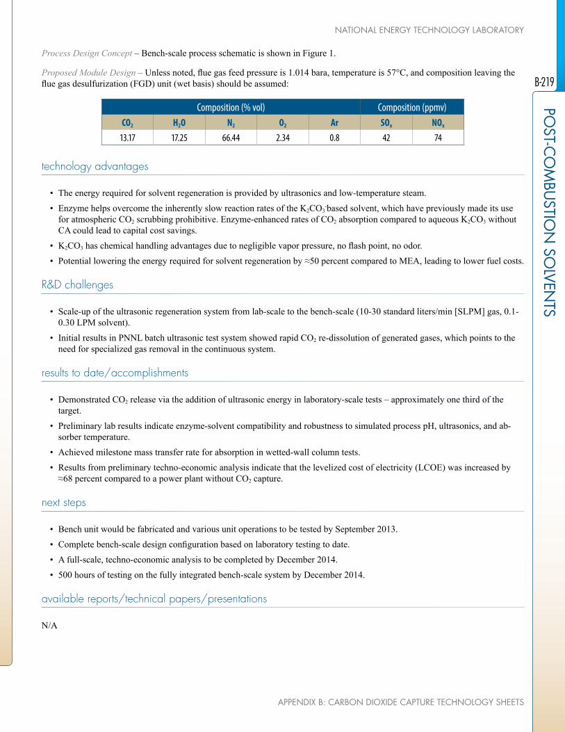
Process Design Concept – Bench-scale process schematic is shown in Figure 1.
Proposed Module Design – Unless noted, flue gas feed pressure is 1.014 bara, temperature is 57°C, and composition leaving the flue gas desulfurization (FGD) unit (wet basis) should be assumed:
Composition (% vol) Composition (ppmv)CO2 H2O N2 O2 Ar SOx NOx
13.17 17.25 66.44 2.34 0.8 42 74
technology advantages
• The energy required for solvent regeneration is provided by ultrasonics and low-temperature steam.
• Enzyme helps overcome the inherently slow reaction rates of the K2CO3-based solvent, which have previously made its use
for atmospheric CO2 scrubbing prohibitive. Enzyme-enhanced rates of CO2 absorption compared to aqueous K2CO3 without CA could lead to capital cost savings.
• K2CO3 has chemical handling advantages due to negligible vapor pressure, no flash point, no odor.
• Potential lowering the energy required for solvent regeneration by ≈50 percent compared to MEA, leading to lower fuel costs.
R&D challenges
• Scale-up of the ultrasonic regeneration system from lab-scale to the bench-scale (10-30 standard liters/min [SLPM] gas, 0.1-0.30 LPM solvent).
• Initial results in PNNL batch ultrasonic test system showed rapid CO2 re-dissolution of generated gases, which points to the need for specialized gas removal in the continuous system.
results to date/accomplishments
• Demonstrated CO2 release via the addition of ultrasonic energy in laboratory-scale tests – approximately one third of the target.
• Preliminary lab results indicate enzyme-solvent compatibility and robustness to simulated process pH, ultrasonics, and ab-sorber temperature.
• Achieved milestone mass transfer rate for absorption in wetted-wall column tests.
• Results from preliminary techno-economic analysis indicate that the levelized cost of electricity (LCOE) was increased by ≈68 percent compared to a power plant without CO2 capture.
next steps
• Bench unit would be fabricated and various unit operations to be tested by September 2013.
• Complete bench-scale design configuration based on laboratory testing to date.
• A full-scale, techno-economic analysis to be completed by December 2014.
• 500 hours of testing on the fully integrated bench-scale system by December 2014.
available reports/technical papers/presentations
N/A
B-219
POST-C
OM
BUSTIO
N SO
LVENTS
APPENDIX B: CARBON DIOXIDE CAPTURE TECHNOLOGY SHEETS
NATIONAL ENERGY TECHNOLOGY LABORATORY
CARBON ABSORBER RETROfIT EQUIPMENT (CARE)
primary project goals
Neumann Systems Group, Inc. (NSG) is designing, constructing, and testing a patented NeuStream™ absorber at the Colorado Springs Utilities (CSU) Drake #7 power plant. The absorber will employ nozzle technology proven during a recently completed 20-MW NeuStream-S flue gas desulfurization (FGD) pilot project, as well as an 8-m piperazine (PZ) solvent, which is more effective for capturing carbon dioxide (CO2).
technical goals
• Design a 0.5-MWe slipstream CO2 scrubber that will minimize parasitic power through efficient design.
• Demonstrate a two-month steady-state operation with a three-stage absorber and a multi-stage stripper.
• Demonstrate 90 percent CO2 capture efficiency utilizing the best available solvent.
• Show unit traceability/scalability to commercial scale.
technical content
NSG will conduct the Carbon Absorber Retrofit Equipment (CARE) project to design, construct, and test the NeuStream-C, a patented absorber technology. The NeuStream-C absorber will use a proven technology with an array of flat jets and an advanced solvent (8 m PZ) to capture CO2. The CARE project will be based on modeling (computational fluid dynamics [CFD] and Aspen Plus) and analysis of carbon capture data from slipstream experiments, where experimental specific surface areas of 440 m2/m3 have been achieved. A compact NeuStream-C module will be inserted post-baghouse into a 0.5-MWe slipstream at the CSU Drake #7 power plant. The slipstream will be equipped with sulfur oxide (SOx) scrubbing and amine washing equipment that also utilizes the NSG flat jet technology. The SOx scrubbing equipment uses compact modular NeuStream technology and can be adjusted to residual SOx level (1 to 30 parts per million [ppm]) prior to CO2 capture. The CARE project will employ slipstream nitrogen oxide (NOx) removal; a four-stage, 0.5-MWe NeuStream-C high-performance absorber unit for scrubbing; a novel stripper design that reduces heat waste; and a flue gas heat-recovery method to offset a portion of steam usage.
technology maturity:
Pilot-Scale, Actual flue Gas Slipstream
project focus:
Carbon Absorber Retrofit Equipment
participant:
Neumann Systems Group
project number:
fE0007528
NETL project manager:
Andy O’[email protected]
principal investigator:
Andrew AwtryNeumann Systems [email protected]
partners:
Colorado Springs UtilitiesUNDEERCIndustrial Constructor ManagersURS
performance period:
1/2/12 – 1/31/15
B-220
POST
-CO
MBU
STIO
N S
OLV
ENTS
U.S. DEPARTMENT Of ENERGY
ADVANCED CARBON DIOXIDE CAPTURE R&D PROGRAM: TECHNOLOGY UPDATE, MAY 2013

figure 1: The System Layout of the 0.5-MW NeuStream™-C Demonstrator System
TABLE 1: PROCESS PARAMETERSUnits Current R&D Value Target R&D Value
Pure Solvent (K2CO2)
Molecular Weight mol-1 86.14 86.14
Normal Boiling Point °C 146 146
Normal Freezing Point °C 48 48
Vapor Pressure @ 15°C bar <0.001 <0.001
Manufacturing Cost for Solvent $/kg
Working Solution
Concentration kg/kg 41% 41%
Specific Gravity (15°C/15°C) - 1.036 1.036
Specific Heat Capacity @ STP kJ/kg-K 3.5 (40 C, 0.41 loading) 3.5 (40 C, 0.41 loading)
Viscosity @ STP cP 10cP @40 C, 0.41 loading 10cP @40 C, 0.41 loading
Absorption
Pressure bar 1 1
Temperature °C 40 40
Equilibrium CO2 Loading mol/mol 0.38 0.38
Heat of Absorption kJ/mol CO2
Solution Viscosity cP
Desorption
Pressure bar 4 8
Temperature °C 150 150
Equilibrium CO2 Loading mol/mol 0.28 0.28
Heat of Desorption kJ/mol CO2
B-221
POST-C
OM
BUSTIO
N SO
LVENTS
APPENDIX B: CARBON DIOXIDE CAPTURE TECHNOLOGY SHEETS
NATIONAL ENERGY TECHNOLOGY LABORATORY

TABLE 1: PROCESS PARAMETERSUnits Current R&D Value Target R&D Value
Proposed Module Design (for equipment developers)
Flue Gas Flowrate kg/hr
CO2 Recovery, Purity, and Pressure % / % / bar 90%, >95%, 4/8 bar
Absorber Pressure Drop bar 0.027
Estimated Absorber/Stripper Cost of Manufacturing and Installation
$
kg/hr
Definitions:
STP – Standard Temperature and Pressure (15°C, 1 atm).
Pure Solvent – Chemical agent(s), working alone or as a component of a working solution, responsible for enhanced CO2 absorp-tion (e.g., the amine monoethanolamine [MEA] in an aqueous solution).
Manufacturing Cost for Solvent – “Current” is market price of chemical, if applicable; “Target” is estimated manufacturing cost for new solvents, or the estimated cost of bulk manufacturing for existing solvents.
Working Solution – The solute-free (i.e., CO2-free) liquid solution used as the working solvent in the absorption/desorption pro-cess (e.g., the liquid mixture of MEA and water).
Absorption – The conditions of interest for absorption are those that prevail at maximum solvent loading, which typically occurs at the bottom of the absorption column. These may be assumed to be 1 atm total flue-gas pressure (corresponding to a CO2 partial pressure of 0.13 bar) and 40°C; however, measured data at other conditions are preferable to estimated data.
Desorption – The conditions of interest for desorption are those that prevail at minimum solvent loading, which typically occurs at the bottom of the desorption column. Operating pressure and temperature for the desorber/stripper are process-dependent (e.g., an MEA-based absorption system has a typical CO2 partial pressure of 1.8 bar and a reboiler temperature of 120°C). Measured data at other conditions are preferable to estimated data.
Pressure – The pressure of CO2 in equilibrium with the solution. If the vapor phase is pure CO2, this is the total pressure; if it is a mixture of gases, this is the partial pressure of CO2. Note that for a typical pulverized coal (PC) power plant, the total pressure of the flue gas is about 1 atm and the concentration of CO2 is about 13.2 percent. Therefore, the partial pressure of CO2 is roughly 0.132 atm or 0.130 bar.
Concentration – Mass fraction of pure solvent in working solution.
Loading – The basis for CO2 loadings is moles of pure solvent.
Estimated Cost – Basis is kg/hr of CO2 in CO2-rich product gas; assuming targets are met.
B-222
POST
-CO
MBU
STIO
N S
OLV
ENTS
U.S. DEPARTMENT Of ENERGY
ADVANCED CARBON DIOXIDE CAPTURE R&D PROGRAM: TECHNOLOGY UPDATE, MAY 2013

Other Parameter Descriptions:
Chemical/Physical Solvent Mechanism – The reaction of PZ with CO2 involves formation of the following four PZ species:
figure 2: Molecular Structure of Piperazine Species1
These reactions are as follows:
1. PZH+ + H2O ↔ PZ + H3O+
2. PZ + CO2 + H2O ↔ PZCOO- + H3O+
3. H2O + H+PZCOO- ↔ H3O+ + PZCOO-
4. PZCOO- + CO2 + H2O ↔ PZ(COO-)2 + H3O+
TABLE 2: EQUILIBRIUM CONSTANTS FOR ABOVE REACTIONS1
Eq. No. Equilibrium Constantln K = A + B/T + C lnT
A B C
1 -11.91 -4,351 –
2 -29.31 5,615 –
3 -8.21 -5,286 –
4 -30.78 5,615 –
This speciation and solubility model has been used to predict the partial pressure of CO2 and mole fraction of species in solution as a function of PZ loading; the results show a good match between the model and the experimental data.
Solvent Contaminant Resistance – 8-m PZ is thermally stable at 150°C with negligible oxidative degradation. The total amine loss is estimated to be 0.4 percent/week when stripping at 150°C. At 135°C, the reported thermal degradation of PZ is 0.07 percent as compared to 8.1 percent in the case of an MEA solvent. The main degradation products of PZ are nitrates (0.13 mM/hr) and ethylenediamine (0.09 mM/hr).
Flue Gas Pretreatment Requirements – The flue gas will be passed through NOx- and SOx-removal systems before feeding to the CARE system. The SOx concentration will be kept below 10 ppm using the existing technology. The polishing scrubber for SOx removal has a high volumetric mass-transfer coefficient and 90 percent removal efficiency. The polishing scrubber also cools the flue gas from 57°C to ≈32°C by contacting the flue gas with cold sorbent. This reduces the volumetric flow rate through the CO2 absorber and counteracts some of the heat from the exothermic CO2 absorption reaction, reducing the PZ solvent temperature and decreasing the equilibrium vapor pressure, both of which help to reduce the size of the CO2 absorber.
B-223
POST-C
OM
BUSTIO
N SO
LVENTS
APPENDIX B: CARBON DIOXIDE CAPTURE TECHNOLOGY SHEETS
NATIONAL ENERGY TECHNOLOGY LABORATORY

Waste Streams Generated – The major amine waste streams come from: (1) post-amine wash, (2) the stripper, and (3) reclaimer waste. Other than these, there could be fugitive liquid amine emissions, which can be controlled by incorporating seamless valves, rupture disks, closed-loop ventilation systems, pumps with dual mechanical seals, minimum welds, and correct gasket material selection. Also, solid waste will be generated in the reclaimer and inline filters.
Process Design Concept – Process flow diagram:
figure 3: Process flow Diagram of CARE System
Proposed Module Design – The system layout is shown above in Figure 1, where Ozone is introduced upstream of a forced draft to oxidize nitric oxide (NOx) to more soluble components. The fan moves the flue gas through a heat exchanger to heat the slipstream flow back up to a representative temperature (350°F). The flue gas then passes through a second heat exchanger, which heats loaded solvent and reduces steam usage in the regeneration subsystem. The flue gas will then pass through an FGD system to reduce the SOx concentration to 15 ppm and the NOx by 80 to 90 percent. A polishing/direct contact cooler (DCC) scrubber is used to further reduce the SOx to 1 ppm, and to cool the flue gas to <35°C. After the polishing/DDC scrubber, the gas passes through a four-unit CO2 absorber (shown in Figure 3), where each unit has three stages. This 12-stage absorber reduces the CO2 by 90 percent prior to contacting the flue gas with an amine wash, which cleans the amine slip from the gas before reintroducing it into the plants main flue gas stream.
B-224
POST
-CO
MBU
STIO
N S
OLV
ENTS
U.S. DEPARTMENT Of ENERGY
ADVANCED CARBON DIOXIDE CAPTURE R&D PROGRAM: TECHNOLOGY UPDATE, MAY 2013

figure 4: Solid Model of One of four Absorber Stages Utilized in Project CARE(The 11-m absorber length will not change with a commercial system; only the cross sectional area
where the gas enters the absorber will increase.)
The regeneration system contains all typical components, such as cross heat exchangers, solvent cooler exchanger, rich pump, reclaimer, and condenser. A custom-designed stripper vessel is utilized in expectation of lowering steam usage during operation. Additionally, approximately 10 percent of the rich flow is directed to a lower-pressure flash vessel to desorb the CO2 from the solvent using only heat provided by the flue gas.
technology advantages
• The NeuStream-C technology integrates a novel absorber design with an advanced solvent, leading to savings in both capital and operating costs compared to conventional systems.
• The high surface areas of the jets and low-pressure drop in the absorber have the potential to lower the capital cost of the absorber considerably, leading to significant reductions in the increase in levelized cost of electricity (LCOE) over MEA.
• The NeuStream-C technology incorporates solvent regeneration at high pressures, leading to lower-compression require-ments.
• The CARE system will utilize an alternative NOx-removal strategy to demonstrate the viability of this option over selective catalytic reductions (SCRs).
• The CARE system will utilize a flue gas heat-recovery strategy to reduce the steam usage in the regeneration subsystem.
• A novel stripper design developed by NSG with Drs. Rochelle and Chen at the University of Texas will be incorporated into the CARE system in an attempt to minimize steam usage.
R&D challenges
• Ensuring optimal dispersion of gas in the absorber, avoiding gas bypassing the jets in large-scale absorbers may be an issue and is being addressed via modeling.
• Results from tests on the design verification stand indicate that the surface area decreased significantly with jet length; this may lead to larger absorbers, increasing capital costs. It is possible this decrease is due to the wall effects that become more prevalent at longer jet lengths in the design verification test stand.
B-225
POST-C
OM
BUSTIO
N SO
LVENTS
APPENDIX B: CARBON DIOXIDE CAPTURE TECHNOLOGY SHEETS
NATIONAL ENERGY TECHNOLOGY LABORATORY

results to date/accomplishments
• Results from the Energy and Environmental Research Center (EERC) tests using a flue gas flow rate of 160 standard cubic feet per minute (SCFM) demonstrated high specific surface areas of 250 to 300 m2/m3 with low-system pressure-drop (0.0361 psi/m of jet or 2.94 mbar/m of jet) with high CO2 capture efficiencies (up to 89%).
• Techno-economic analysis of the NeuStream-C by EERC indicated that the increase in LCOE over a sub-critical power plant without CO2 capture would be approximately 40 percent, and the cost of CO2 capture is at $28.50/ton.
• A design verification and testing (DVT) stand (300 to 2200 SCFM gas flow rate) was used to validate the preliminary design of the 0.5-MW CARE unit (absorber, pumps, heat exchangers, strippers) and was completed by NSG.
• It was found that wire meshes and directional vanes at the entrance resulted in an optimal dispersion of gas in the absorber by conducting CFD simulations.
• Investigations of the effects of jet length, gas velocity, nozzle spacing, and nozzle pressure on the CO2 capture efficiency and the rate of CO2 absorption in the DVT stand demonstrated high surface areas (300 to 450 m2/m3) for 22- to 12-inch long jets, respectively.
next steps
• Work is still ongoing to reduce the perceived wall losses and maximize the specific surface area utilized in the 0.5-MW dem-onstrator.
• A next generation low-flow nozzle is being developed that will reduce the parasitic power of the absorber system while main-taining a high contact area.
• The CARE pilot system has completed its final design review and is expecting to start BP2 in May 2013, which involves construction of the system.
available reports/technical papers/presentations
Brasseur, J., and Awtry, A., “Compact absorber retrofit equipment (CARE),” presented at the 2012 NETL CO2 Capture Tech-nology Meeting, July 2012, Pittsburgh, PA. http://www.netl.doe.gov/publications/proceedings/12/co2capture/presentations/2-Tuesday/2-Brasseur-NeumannSG.pdf.
Bishnoi, S., and Rochelle, G. T., “Absorption of carbon dioxide into aqueous piperazine: reaction kinetics, mass transfer and solu-bility,” Chemical Engineering Science 55 (2000) 5531-5543.
B-226
POST
-CO
MBU
STIO
N S
OLV
ENTS
U.S. DEPARTMENT Of ENERGY
ADVANCED CARBON DIOXIDE CAPTURE R&D PROGRAM: TECHNOLOGY UPDATE, MAY 2013

COMBINED PRESSURE AND TEMPERATURE CONTRAST SEPARATION Of CARBON DIOXIDE fOR POST-COMBUSTION CARBON CAPTURE
primary project goals
Rice University is developing a hybrid carbon dioxide (CO2) absorption process combining absorber and stripper columns using a high surface area ceramic foam gas-liquid contactor for enhanced mass transfer and utilizing waste heat for regeneration. The project includes bench-scale testing of the system.
technical goals
• Combine absorber and stripper columns into a single, integrated process unit.
• Use vacuum stripping in combination with waste heat for regeneration.
• Determine best absorbent and operating conditions for the process.
technical content
The project includes investigating the following concepts:
• Combining the absorber and stripper columns into a single, integrated unit to mitigate space availability constraints.
• The use of vacuum stripping in combination with waste heat for regeneration of CO2 absorbent.
• The use of a high surface area ceramic foam gas-liquid contactor for enhanced mass transfer.
• Determining the best absorbent and operating conditions for the process.
• Effect of the addition of a co-solvent on reboiler energy duty and CO2 absorption kinet-ics.
technology maturity:
Bench-Scale, Simulated flue Gas
project focus:
Hybrid Absorption/Stripper Process
participant:
William Marsh Rice University
project number:
fE0007531
NETL project manager:
Elaine [email protected]
principal investigator:
George HirasakiWilliam Marsh Rice [email protected]
partners:
N/A
performance period:
10/1/11 – 9/30/14
B-227
POST-C
OM
BUSTIO
N SO
LVENTS
APPENDIX B: CARBON DIOXIDE CAPTURE TECHNOLOGY SHEETS
NATIONAL ENERGY TECHNOLOGY LABORATORY
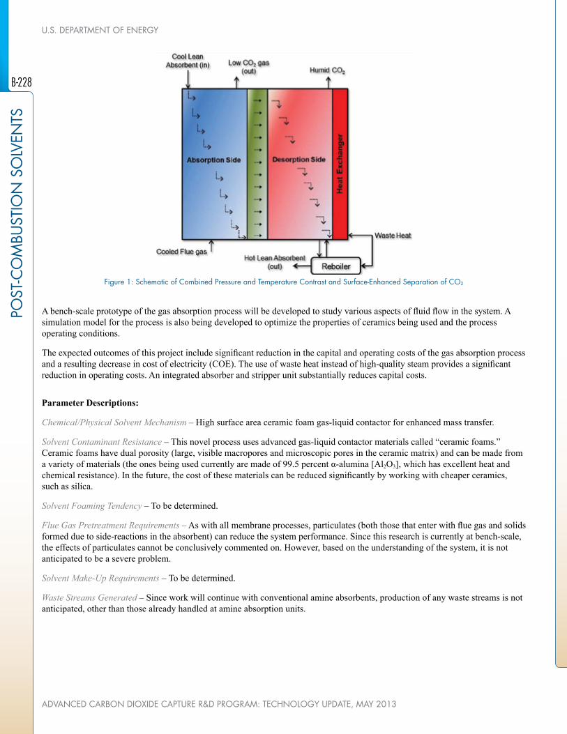
figure 1: Schematic of Combined Pressure and Temperature Contrast and Surface-Enhanced Separation of CO2
A bench-scale prototype of the gas absorption process will be developed to study various aspects of fluid flow in the system. A simulation model for the process is also being developed to optimize the properties of ceramics being used and the process operating conditions.
The expected outcomes of this project include significant reduction in the capital and operating costs of the gas absorption process and a resulting decrease in cost of electricity (COE). The use of waste heat instead of high-quality steam provides a significant reduction in operating costs. An integrated absorber and stripper unit substantially reduces capital costs.
Parameter Descriptions:
Chemical/Physical Solvent Mechanism – High surface area ceramic foam gas-liquid contactor for enhanced mass transfer.
Solvent Contaminant Resistance – This novel process uses advanced gas-liquid contactor materials called “ceramic foams.” Ceramic foams have dual porosity (large, visible macropores and microscopic pores in the ceramic matrix) and can be made from a variety of materials (the ones being used currently are made of 99.5 percent α-alumina [Al2O3], which has excellent heat and chemical resistance). In the future, the cost of these materials can be reduced significantly by working with cheaper ceramics, such as silica.
Solvent Foaming Tendency – To be determined.
Flue Gas Pretreatment Requirements – As with all membrane processes, particulates (both those that enter with flue gas and solids formed due to side-reactions in the absorbent) can reduce the system performance. Since this research is currently at bench-scale, the effects of particulates cannot be conclusively commented on. However, based on the understanding of the system, it is not anticipated to be a severe problem.
Solvent Make-Up Requirements – To be determined.
Waste Streams Generated – Since work will continue with conventional amine absorbents, production of any waste streams is not anticipated, other than those already handled at amine absorption units.
B-228
POST
-CO
MBU
STIO
N S
OLV
ENTS
U.S. DEPARTMENT Of ENERGY
ADVANCED CARBON DIOXIDE CAPTURE R&D PROGRAM: TECHNOLOGY UPDATE, MAY 2013

technology advantages
• Waste heat used for absorbent regeneration significantly reduces parasitic duty for a power plant and will limit the increase in COE.
• Operating the desorber at lower temperatures decreases amine losses and equipment corrosion problems.
• Addition of a co-solvent to the amine absorbent can potentially reduce the energy consumption for regeneration.
R&D challenges
• Scalability.
• Lack of published literature describing the performance of ceramic foams as tower packing.
• Lack of process model.
• Pairing a conventional absorption process with a vacuum stripper.
• Lack of thermodynamic data and models to describe the effects of co-solvents.
results to date/accomplishments
• Studied hydrodynamic properties of off-the-shelf alumina foams purchased from commercial supplier.
• Compared the CO2-pickup performance of 20-, 30-, and 45-ppi alumina foam with that of 6-mm Raschig rings; also esti-mated the performance for 25-mm Raschig rings. Estimates show that 20-ppi ceramic foam has a better performance than the 25-mm Raschig rings.
• Performed an initial technical and economic feasibility study to demonstrate that the process proposed by the Rice University team has a capital cost comparable to that of the Fluor Econamine process and results in significantly lower COE with the use of waste heat.
• Completed design for bench-scale combined absorption/desorption unit.
• Demonstrated CO2 absorption and desorption using 30 wt% Diglycolamine in an integrated absorber-stripper unit made with stainless steel.
next steps
Develop a model to simulate and optimize system performance.
available reports/technical papers/presentations
“Combined Pressure and Temperature Contrast and Surface-Enhanced Separation of Carbon Dioxide for Post-Combustion Carbon Capture,” presented at the 2012 NETL CO2 Capture Technology Meeting, Pittsburgh, Pennsylvania, July 2012. http://www.netl.doe.gov/File%20Library/events/2012/co2%20capture%20meeting/G-Hirasaki-Rice-Combined-Separations.pdf
B-229
POST-C
OM
BUSTIO
N SO
LVENTS
APPENDIX B: CARBON DIOXIDE CAPTURE TECHNOLOGY SHEETS
NATIONAL ENERGY TECHNOLOGY LABORATORY

DEVELOPMENT Of A NOVEL GAS-PRESSURED STRIPPING (GPS) PROCESS-BASED TECHNOLOGY fOR CO2 CAPTURE fROM POST-COMBUSTION fLUE GASES
primary project goals
Carbon Capture Scientific is performing bench-scale development, testing, and computer simulations of a novel solvent-based carbon dioxide (CO2) capture technology, known as a Gas-Pressurized Stripping (GPS) Process. The GPS technology has the potential to signifi-cantly reduce the energy penalty associated with solvent regeneration and compression by operating the regeneration step at higher pressures, which in turn reduces the compression requirements for CO2 storage.
technical goals
• Computer simulation to predict GPS column performance under different operating conditions.
• Experimental validation of use of a modified commercial solvent system in the GPS process to ensure that it can perform efficiently under process conditions.
• Documentation of experimental results and obtaining necessary information to progress the technology.
technical content
Carbon Capture Scientific is developing and testing a novel, proprietary, GPS process-based technology for CO2 capture from post-combustion flue gases. The project will conduct individual unit bench-scale tests for four major process components, including a first absorption column, a GPS column, a second absorption column, and a flash vessel, as well as bench-scale tests for an integrated continuous GPS system test at the National Carbon Capture Center (NCCC). The overall objective is to reduce the energy consumption of the CO2 stripping process and the subsequent compression, leading to overall reduced costs. A computer simulation task will be carried out to study the GPS column behavior under different operating conditions, optimizing the column design and operating conditions. Two additional computer simulation tasks will then be performed to optimize the GPS process for both an existing and new power plant. A solvent stability study will collect information on the solvent operating cost when a modified, commercially available solvent is used in the GPS process. Figure 1 is a flow chart for the single-solvent GPS process. Table 1 lists the process parameters relevant to the GPS process.
technology maturity:
Bench-Scale, Simulated flue Gas
project focus:
Gas-Pressurized Stripping
participant:
Carbon Capture Scientific
project number:
fE0007567
NETL project manager:
Andrew [email protected]
principal investigator:
Shiaoguo (Scott) ChenCarbon Capture Scientific, [email protected]
partners:
CONSOL Energy IncNexant IncWestern Kentucky University
performance period:
10/1/11 – 9/30/14
B-230
POST
-CO
MBU
STIO
N S
OLV
ENTS
U.S. DEPARTMENT Of ENERGY
ADVANCED CARBON DIOXIDE CAPTURE R&D PROGRAM: TECHNOLOGY UPDATE, MAY 2013

figure 1: GPS-Based Absorption/Stripping Process – Single Solvent
TABLE 1: PROCESS PARAMETERSUnits Current R&D Value Target R&D Value
Pure Solvent
Molecular Weight mol-1 Varied Varied
Normal Boiling Point °C Varied Varied
Normal Freezing Point °C Varied Varied
Vapor Pressure @ 15°C bar Varied Varied
Manufacturing Cost for Solvent $/kg Varied Varied
Working Solution
Concentration kg/kg 3.8 5.0
Specific Gravity (15°C/15°C) -
Specific Heat Capacity @ STP kJ/kg-K ca. 3 ca. 3
Viscosity @ STP cP
Absorption
Pressure bar 1 1
Temperature °C 40 40
Equilibrium CO2 Loading mol/mol Varied Varied
Heat of Absorption kJ/mol CO2 Varied Varied
Solution Viscosity cP 6 6
Desorption
Pressure bar 10 10
Temperature °C 120 130
Equilibrium CO2 Loading mol/mol Varied Varied
Heat of Desorption kJ/mol CO2
B-231
POST-C
OM
BUSTIO
N SO
LVENTS
APPENDIX B: CARBON DIOXIDE CAPTURE TECHNOLOGY SHEETS
NATIONAL ENERGY TECHNOLOGY LABORATORY

TABLE 1: PROCESS PARAMETERSUnits Current R&D Value Target R&D Value
Proposed Module Design (for equipment developers)
Flue Gas Flowrate kg/hr 40
CO2 Recovery, Purity, and Pressure % / % / bar 90%, >95%, 10 bar
Adsorber Pressure Drop bar 0
Estimated Absorber/Stripper Cost of Manufacturing and Installation
$
kg/hr $500,000
Definitions:
STP – Standard Temperature and Pressure (15°C, 1 atm).
Pure Solvent – Chemical agent(s), working alone or as a component of a working solution, responsible for enhanced CO2 absorp-tion (e.g., the amine MEA in an aqueous solution).
Manufacturing Cost for Solvent – “Current” is market price of chemical, if applicable; “Target” is estimated manufacturing cost for new solvents, or the estimated cost of bulk manufacturing for existing solvents.
Working Solution – The solute-free (i.e., CO2-free) liquid solution used as the working solvent in the absorption/desorption pro-cess (e.g., the liquid mixture of MEA and water).
Absorption – The conditions of interest for absorption are those that prevail at maximum solvent loading, which typically occurs at the bottom of the absorption column. These may be assumed to be 1 atm total flue-gas pressure (corresponding to a CO2 partial pressure of 0.13 bar) and 40°C; however, measured data at other conditions are preferable to estimated data.
Desorption – The conditions of interest for desorption are those that prevail at minimum solvent loading, which typically occurs at the bottom of the desorption column. Operating pressure and temperature for the desorber/stripper are process-dependent (e.g., an MEA-based absorption system has a typical CO2 partial pressure of 1.8 bar and a reboiler temperature of 120°C). Measured data at other conditions are preferable to estimated data.
Pressure – The pressure of CO2 in equilibrium with the solution. If the vapor phase is pure CO2, this is the total pressure; if it is a mixture of gases, this is the partial pressure of CO2. Note that for a typical PC power plant, the total pressure of the flue gas is about 1 atm and the concentration of CO2 is about 13.2 percent. Therefore, the partial pressure of CO2 is roughly 0.132 atm or 0.130 bar.
Concentration – Mass fraction of pure solvent in working solution.
Loading – The basis for CO2 loadings is moles of pure solvent.
Estimated Cost – Basis is kg/hr of CO2 in CO2-rich product gas; assuming targets are met.
Other Parameter Descriptions:
Chemical/Physical Solvent Mechanism – PS is a process applicable to different types of solvents. Chemistry of the GPS-based absorption/stripping process depends on the solvent used in the process. In the proposed research, a modified commercially avail-able amine solvent will be used. Therefore, the chemistry of the amine-based CO2 capture process will apply to the GPS-based process.
The reaction kinetics of the GPS-based process also depends on the solvent selected. With the solvent currently selected, it is believed that the reaction kinetics of the modified commercially available solvent will perform better than the baseline monoetha-nolamine (MEA) process.
B-232
POST
-CO
MBU
STIO
N S
OLV
ENTS
U.S. DEPARTMENT Of ENERGY
ADVANCED CARBON DIOXIDE CAPTURE R&D PROGRAM: TECHNOLOGY UPDATE, MAY 2013

Solvent Contaminant Resistance – Since the selected solvent is an amine-based solvent, it will share common issues that other amine-based solvents have. Sulfur oxide (SOx) and nitrogen oxide (NOx) could be the major contaminants in flue gas, which will be detrimental to all amine-based solvents, including the solvent used in this process. Similar to other amine-based solvents, pre-treatment of flue gas will be required to minimize amine degradations.
Solvent Foaming Tendency – The solvent is a commercially available solvent, with different strength. The solvent forming ten-dency should be manageable based on industrial experience.
Flue Gas Pretreatment Requirements – No special heating/cooling methods are required in the GPS-based absorption/stripping process. Steam will be used to heat solvent indirectly, and cooling water will be used to cool solvent indirectly whenever solvent cooling is required.
Solvent Make-Up Requirements – Solvent stability study has demonstrated that this commercially available solvent will have solvent make-up rate of 1 kg solvent/tonne CO2.
Waste Streams Generated – Waste stream of the GPS-based process is also similar to other amine-based absorption/stripping pro-cesses. The main waste material is amine degradation products.
Process Design Concept – Flowsheet/block flow diagram of the GPS process is shown in Figure 1. It is virtually a combination of two conventional absorption/stripping process, with the second one being inserted into the first one. This process configuration will be able to save sensible heat.
Proposed Module Design – Unless noted, flue gas feed pressure is 1.014 bara, temperature is 57°C, and composition leaving the flue gas desulfurization (FGD) unit (wet basis) should be assumed:
Composition (% vol) Composition (ppmv)CO2 H2O N2 O2 Ar SOx NOx
13.17 17.25 66.44 2.34 0.8 42 74
technology advantages
• The use of the off-the-shelf process equipment will accelerate the process development.
• The use of absorption/stripping technology would be suitable for low-cost, large-scale applications.
• The higher stripper operating pressure results in much less sensible heat requirement and less subsequent compression work.
• High-energy efficiency of the process due to application of the GPS concept.
• The GPS technology is flexible in terms of operating pressures and temperatures, and is applicable to different types of solvents.
B-233
POST-C
OM
BUSTIO
N SO
LVENTS
APPENDIX B: CARBON DIOXIDE CAPTURE TECHNOLOGY SHEETS
NATIONAL ENERGY TECHNOLOGY LABORATORY

R&D challenges
The major challenge of the GPS-based process is its high capital cost. The GPS-based process has one more absorption/stripping step and thus leads to a higher capital cost than the baseline process. However, introduction of several novel process concepts has reduced the capital cost of the GPS-based process to less than 120 percent of the baseline capital cost. New process equipment, which has the potential to significantly reduce capital cost, is also being tested.
results to date/accomplishments
• Computer simulation achieved GPS column thermal efficiency of 79 percent.
• Computer simulations indicated that overall process energy performance of 0.20 kWh/kgCO2.
• All the four individual unit bench-scale tests have been completed.
• GPS column tests demonstrated that the thermal efficiency of the GPS column can achieve over 70 percent.
• Thermal stability of the selected solvent has been tested and solvent loss was found to be lower than 1 kg/ton CO2, exceeding the target.
• Oxidative stability tests of the solvent have been completed and the results showed negligible oxidative degradation.
• A preliminary techno-economic analysis has been conducted and the results showed that a levelized cost of electricity (LCOE) increase of 61 percent over the baseline can be achieved.
next steps
• Using computer simulation to further optimize GPS process to reduce capital cost.
• Establish a continuous GPS system skid to conduct shakedown tests and real flue gas tests at NCCC.
• Conduct individual unit test for two intensified process equipment to validate its applicability to post-combustion CO2 cap-ture.
• Set up a system to measure the corrosiveness of the selected solvent at different operating conditions.
• Refine the process simulation results for GPS-based technology to optimize the overall economic performance of the GPS-based process.
available reports/technical papers/presentations
N/A
B-234
POST
-CO
MBU
STIO
N S
OLV
ENTS
U.S. DEPARTMENT Of ENERGY
ADVANCED CARBON DIOXIDE CAPTURE R&D PROGRAM: TECHNOLOGY UPDATE, MAY 2013

CO2-BINDING ORGANIC LIQUIDS GAS CAPTURE WITH POLARITY-SWING-ASSISTED REGENERATION
primary project goals
The primary project goal is to determine design parameters for scale-up of a carbon dioxide (CO2) capture process using novel non-aqueous switchable organic solvents (CO2-binding organic liquids [CO2BOLs]) by conducting bench-scale studies, and to evaluate the ef-fectiveness of polarity-swing-assisted regeneration (PSAR) in lowering temperatures and energies required for CO2 separation.
technical goals
• Measure solvent state-point data (specific heat, density, vapor pressure, and viscosity).
• Measure CO2 loading in the solvent at various temperatures, pressures, water content, and anti-solvent compositions.
• Measure kinetics of CO2 absorption using a wetted-wall column (WWC).
• Develop and verify the performance of coupling CO2BOLs with PSAR.
• Conduct an initial techno-economic assessment using simulation tools to assess feasi-bility.
technical content
CO2BOLs are a class of switchable ionic liquids (ILs; i.e., molecular liquids which become ionic in the presence of CO2) having lower specific heat capacities and higher CO2 working capacities compared to aqueous amines, resulting in potential savings in the sensible heat required to strip CO2.
figure 1: Uptake of CO2 by Alkanolguanidine BOL (left), and formation of Zwitterionic CO2BOL (right)
Similar to aqueous amines, CO2BOLs are basic, but the base (e.g., guanidine, amidine) does not directly react with CO2. Instead, the alcohol component reacts with CO2, forming alkyl carbonic acid, and subsequently transfers a proton to the base, forming liquid alkylcarbon-ate. The current generation of CO2BOLs combine the base and the alcohol moieties in a single molecule, lowering volatility (Figure 1).
The addition of non-polar solvent (anti-solvent) to CO2BOLs and other switchable solvents
technology maturity:
Laboratory-Scale, Simulated flue Gas
project focus:
CO2BOLs with Polarity-Swing-Assisted Regeneration
participant:
Battelle Memorial Institute
project number:
fE0007466
NETL project manager:
I. Andrew [email protected]
principal investigator:
David HeldebrantBattelle Memorial [email protected]
partners:
The fluor CorporationQueens University
performance period:
10/1/11 – 3/31/14
B-235
POST-C
OM
BUSTIO
N SO
LVENTS
APPENDIX B: CARBON DIOXIDE CAPTURE TECHNOLOGY SHEETS
NATIONAL ENERGY TECHNOLOGY LABORATORY
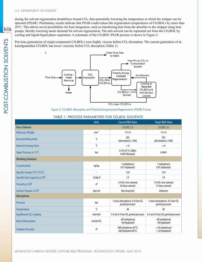
during the solvent regeneration destabilizes bound CO2, thus potentially lowering the temperature at which the stripper can be operated (PSAR). Preliminary results indicate that PSAR could reduce the regeneration temperatures of CO2BOLs by more than 20°C. This allows novel possibilities for heat integration, such as transferring heat from the absorber to the stripper using heat pumps, thereby lowering steam demand for solvent regeneration. The anti-solvent can be separated out from the CO2BOL by cooling and liquid-liquid phase separation. A schematic of the CO2BOL-PSAR process is shown in Figure 2.
Previous generations of single-component CO2BOLs were highly viscous before CO2 absorption. The current generation of al-kanolguanidine CO2BOL has lower viscosity before CO2 absorption (Table 1).
figure 2: CO2BOL Absorption and Polarity-Swing-Assisted Regeneration (PSAR) Process
TABLE 1: PROCESS PARAMETERS FOR CO2BOL SOLVENTSUnits Current R&D Value Target R&D Value
Pure Solvent CO2BOL (3) CO2BOL (3)
Molecular Weight mol-1 171.14 171.14
Normal Boiling Point °C 262(decomposes >200)
262(decomposes >200)
Normal Freezing Point °C < 0 < 0
Vapor Pressure @ 15°C bar 0.179 (37˚C) (DBU) 0.009 (Butanol) 0.0001
Working Solution
Concentration kg/kg 1 (anhydrous)0.91 (hydrated)
1 (anhydrous)0.91 (hydrated)
Specific Gravity (15°C/15°C) - 1.03 1.03
Specific Heat Capacity @ STP kJ/kg-K 1.9 1.9
Viscosity @ STP cP 1.9 (CO2-free solvent)50 (lean solvent)
1.9 (CO2-free solvent)11 (lean solvent)
Surface Tension @ STP dyn/cm Not measured Unknown
Absorption
Pressure bar 1 (near atmospheric, 0.15 bar CO2 partial pressure)
1 (near atmospheric, 0.15 bar CO2 partial pressure)
Temperature °C 40 40
Equilibrium CO2 Loading mol/mol 0.5 (at 0.15 bar CO2 partial pressure) 0.5 (at 0.15 bar CO2 partial pressure)
Heat of Absorption kJ/mol CO2-80 (anhydrous)-90 (hydrated)
-80 (anhydrous)-90 (hydrated)
Solution Viscosity cP 400 (anhydrous 40°C)500 (hydrated 40°C)
< 20 (anhydrous)< 20 (hydrated)
B-236
POST
-CO
MBU
STIO
N S
OLV
ENTS
U.S. DEPARTMENT Of ENERGY
ADVANCED CARBON DIOXIDE CAPTURE R&D PROGRAM: TECHNOLOGY UPDATE, MAY 2013

TABLE 1: PROCESS PARAMETERS FOR CO2BOL SOLVENTSUnits Current R&D Value Target R&D Value
Desorption
Pressure bar 2 2
Temperature °C 120 (thermal only)<100 (PSAR)
<100 (thermal only)75 (PSAR)
Equilibrium CO2 Loading mol/mol 0.25° 0.25
Heat of Desorption kJ/mol CO2-80 (anhydrous)-90 (hydrated)
-80 (anhydrous)-90 (hydrated)
Definitions:
STP – Standard Temperature and Pressure (15°C, 1 atm).
Pure Solvent – Chemical agent(s), working alone or as a component of a working solution, responsible for enhanced CO2 absorp-tion (e.g., the amine monoethanolamine [MEA] in an aqueous solution).
Manufacturing Cost for Solvent – “Current” is market price of chemical, if applicable; “Target” is estimated manufacturing cost for new solvents, or the estimated cost of bulk manufacturing for existing solvents.
Working Solution – The solute-free (i.e., CO2-free) liquid solution used as the working solvent in the absorption/desorption pro-cess (e.g., the liquid mixture of MEA and water).
Absorption – The conditions of interest for absorption are those that prevail at maximum solvent loading, which typically occurs at the bottom of the absorption column. These may be assumed to be 1 atm total flue-gas pressure (corresponding to a CO2 partial pressure of 0.13 bar) and 40°C; however, measured data at other conditions are preferable to estimated data.
Desorption – The conditions of interest for desorption are those that prevail at minimum solvent loading, which typically occurs at the bottom of the desorption column. Operating pressure and temperature for the desorber/stripper are process-dependent (e.g., an MEA-based absorption system has a typical CO2 partial pressure of 1.8 bar and a reboiler temperature of 120°C). Measured data at other conditions are preferable to estimated data.
Pressure – The pressure of CO2 in equilibrium with the solution. If the vapor phase is pure CO2, this is the total pressure; if it is a mixture of gases, this is the partial pressure of CO2. Note that for a typical pulverized-coal power plant, the total pressure of the flue gas is about 1 atm and the concentration of CO2 is about 13.2 percent. Therefore, the partial pressure of CO2 is roughly 0.132 atm or 0.130 bar.
Concentration – Mass fraction of pure solvent in working solution.
Loading – The basis for CO2 loadings is moles of pure solvent.
Estimated Cost – Basis is kg/hr of CO2 in CO2-rich product gas; assuming targets are met.
Other Parameter Descriptions:
Chemical Solvent Mechanism – Chemical reaction for the CO2 capture process is shown in Figure 1.
Solvent Contaminant Resistance – Tests of CO2BOL reactivity with hydrogen chloride (HCl), sulfur oxide (SOx) and nitrogen oxide (NOx) are to be conducted. In general, CO2BOLs form heat-stable salts (HSS) with sulfur dioxide (SO2), NOx, and HCl. The solvent can be recovered from the HSS using caustic wash or with ion exchange resins. Levels of HSS formation are expected to be similar to that of MEA. Minimal adverse impacts due to arsenic and mercury in the flue gas are expected.
Solvent Foaming Tendency – Foaming tendency has not been tested and is unknown at this time.
Flue Gas Pretreatment Requirements – Water management with the alkanolguanidine CO2BOL is different from that of MEA. The presence of water increases solution viscosity and increases the energy required to regenerate the CO2BOL. A refrigeration unit
B-237
POST-C
OM
BUSTIO
N SO
LVENTS
APPENDIX B: CARBON DIOXIDE CAPTURE TECHNOLOGY SHEETS
NATIONAL ENERGY TECHNOLOGY LABORATORY
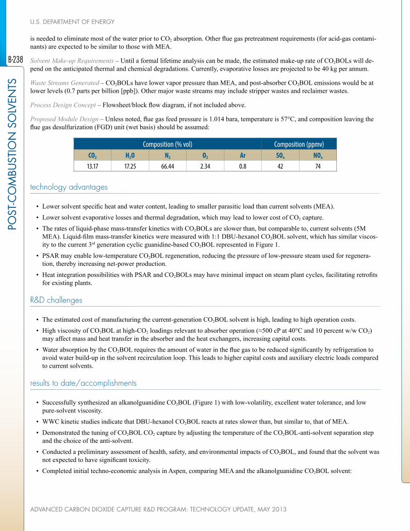
is needed to eliminate most of the water prior to CO2 absorption. Other flue gas pretreatment requirements (for acid-gas contami-nants) are expected to be similar to those with MEA.
Solvent Make-up Requirements – Until a formal lifetime analysis can be made, the estimated make-up rate of CO2BOLs will de-pend on the anticipated thermal and chemical degradations. Currently, evaporative losses are projected to be 40 kg per annum.
Waste Streams Generated – CO2BOLs have lower vapor pressure than MEA, and post-absorber CO2BOL emissions would be at lower levels (0.7 parts per billion [ppb]). Other major waste streams may include stripper wastes and reclaimer wastes.
Process Design Concept – Flowsheet/block flow diagram, if not included above.
Proposed Module Design – Unless noted, flue gas feed pressure is 1.014 bara, temperature is 57°C, and composition leaving the flue gas desulfurization (FGD) unit (wet basis) should be assumed:
Composition (% vol) Composition (ppmv)CO2 H2O N2 O2 Ar SOx NOx
13.17 17.25 66.44 2.34 0.8 42 74
technology advantages
• Lower solvent specific heat and water content, leading to smaller parasitic load than current solvents (MEA).
• Lower solvent evaporative losses and thermal degradation, which may lead to lower cost of CO2 capture.
• The rates of liquid-phase mass-transfer kinetics with CO2BOLs are slower than, but comparable to, current solvents (5M MEA). Liquid-film mass-transfer kinetics were measured with 1:1 DBU-hexanol CO2BOL solvent, which has similar viscos-ity to the current 3rd generation cyclic guanidine-based CO2BOL represented in Figure 1.
• PSAR may enable low-temperature CO2BOL regeneration, reducing the pressure of low-pressure steam used for regenera-tion, thereby increasing net-power production.
• Heat integration possibilities with PSAR and CO2BOLs may have minimal impact on steam plant cycles, facilitating retrofits for existing plants.
R&D challenges
• The estimated cost of manufacturing the current-generation CO2BOL solvent is high, leading to high operation costs.
• High viscosity of CO2BOL at high-CO2 loadings relevant to absorber operation (≈500 cP at 40°C and 10 percent w/w CO2) may affect mass and heat transfer in the absorber and the heat exchangers, increasing capital costs.
• Water absorption by the CO2BOL requires the amount of water in the flue gas to be reduced significantly by refrigeration to avoid water build-up in the solvent recirculation loop. This leads to higher capital costs and auxiliary electric loads compared to current solvents.
results to date/accomplishments
• Successfully synthesized an alkanolguanidine CO2BOL (Figure 1) with low-volatility, excellent water tolerance, and low pure-solvent viscosity.
• WWC kinetic studies indicate that DBU-hexanol CO2BOL reacts at rates slower than, but similar to, that of MEA.
• Demonstrated the tuning of CO2BOL CO2 capture by adjusting the temperature of the CO2BOL-anti-solvent separation step and the choice of the anti-solvent.
• Conducted a preliminary assessment of health, safety, and environmental impacts of CO2BOL, and found that the solvent was not expected to have significant toxicity.
• Completed initial techno-economic analysis in Aspen, comparing MEA and the alkanolguanidine CO2BOL solvent:
B-238
POST
-CO
MBU
STIO
N S
OLV
ENTS
U.S. DEPARTMENT Of ENERGY
ADVANCED CARBON DIOXIDE CAPTURE R&D PROGRAM: TECHNOLOGY UPDATE, MAY 2013

- Parasitic energy consumed by CO2BOL was found to be 84 percent of the energy consumed using MEA as a solvent. - Demonstrated that the levelized cost of electricity (LCOE) using CO2BOL (without PSAR) is on parity with MEA.
next steps
• Anti-solvent/CO2BOL blends would be optimized, and lower-cost synthesis routes would be evaluated by April 2014.
• Continuous bench-scale testing would be performed to assess the effects of higher-solvent viscosity at absorber operating conditions by April 2014.
• Techno-economic assessment of PSAR using process simulations would be finalized by April 2014.
• Several strategies to overcome high-solvent viscosity, including modified CO2BOL chemistry and the use of anti-solvent as diluent, would be tested by April 2014.
available reports/technical papers/presentations
Heldebrant, David, “CO2-Binding Organic Liquids, Enhanced CO2 Capture Process with a Polarity-Swing-Assisted Regenera-tion,” presented at the 2012 CO2 Capture Technology Meeting, July 2012, Pittsburgh, PA. http://www.netl.doe.gov/publications/proceedings/12/co2capture/presentations/2-Tuesday/D%20Heldebrant-Battelle-PSAR.pdf
B-239
POST-C
OM
BUSTIO
N SO
LVENTS
APPENDIX B: CARBON DIOXIDE CAPTURE TECHNOLOGY SHEETS
NATIONAL ENERGY TECHNOLOGY LABORATORY

BENCH-SCALE DEVELOPMENT Of A HOT CARBONATE ABSORPTION PROCESS WITH CRYSTALLIZATION-ENABLED HIGH-PRESSURE STRIPPING fOR POST-COMBUSTION CO2 CAPTURE
primary project goals
The Univirsity of Illinois at Urbana-Champaign (UIUC) is performing a proof-of-concept study that will generate process engineering and scale-up data to optimize the Hot Carbon-ate Absorption Process with Crystallization-Enabled High-Pressure Stripping (Hot-CAP) technology. The study will demonstrate its capability to achieve the U.S. Department of Energy (DOE) goals of at least 90 percent carbon dioxide (CO2) removal from coal-fired power plant flue gas with less than a 35 percent increase in the cost of electricity (COE), helping to advance the process to pilot-scale level within three years.
technical goals
• Perform laboratory- and bench-scale tests to measure thermodynamic and reaction en-gineering data that will be used to evaluate technical feasibility and cost-effectiveness, performance of scale-up, and commercial competitiveness of the Hot-CAP process with Monoethanolamine (MEA)-based processes and other emerging post-combustion CO2 capture technologies.
• A combination of experimental, modeling, process simulation, and technical and eco-nomic analysis studies will be performed.
technical content
For this three-year project, UIUC and Carbon Capture Scientific, LLC will investigate a Hot-CAP to overcome the energy use disadvantage of the MEA-based processes. A prelimi-nary technical-economic evaluation shows that the energy use of the Hot-CAP is about 40 percent less than that of its MEA counterpart, and the process has the potential to meet or exceed DOE’s technical and cost goals of greater than or equal to 90 percent CO2 removal and less than or equal to a 35 percent increase in the COE.
The Hot-CAP is an absorption-based, post-combustion CO2 technology that uses a carbon-ate salt (K2CO3 or Na2CO3) as a solvent. The process integrates a high-temperature (70 to 80°C) CO2 absorption column, a slurry-based high-pressure (up to 40 atm) CO2 stripping column, a crystallization unit to separate bicarbonate and recover the carbonate solvent, and a reclaimer to recover CaSO4 as the byproduct of the sulfur dioxide (SO2) removal.
Project objectives include performing a proof-of-concept study aimed at generating process
technology maturity:
Laboratory-Scale, Simulated flue Gas
project focus:
Hot Carbonate Absorption with Crystallization-Enabled High-Pressure Stripping
participant:
University of Illinois at Urbana-Champaign
project number:
fE0004360
NETL project manager:
Andrew [email protected]
principal investigator:
Yongqi LuUniversity of Illinois at [email protected]
partners:
Carbon Capture Scientific, LLC
performance period:
1/1/11 – 3/31/14
B-240
POST
-CO
MBU
STIO
N S
OLV
ENTS
U.S. DEPARTMENT Of ENERGY
ADVANCED CARBON DIOXIDE CAPTURE R&D PROGRAM: TECHNOLOGY UPDATE, MAY 2013

engineering and scale-up data to help advance the Hot-CAP technology to pilot-scale demonstration level within three years. The project tasks employ lab- and bench-scale test facilities to measure thermodynamic and reaction engineering data that can help evaluate technical feasibility and cost-effectiveness, performance of scale-up, and commercial competitiveness of the Hot-CAP compared to the MEA-based processes and other emerging post-combustion CO2 capture technologies.
To meet project objectives, lab- and bench-scale tests will be performed by UIUC to measure the kinetics and phase equilibrium data associated with the major reactions and unit operations in the Hot-CAP, including CO2 absorption, bicarbonate crystalliza-tion, sulfate recovery, and CO2 stripping. Carbon Capture Scientific, LLC will use the results from the lab- and bench-scale stud-ies to help create a process flow diagram, perform equipment and process simulations, and conduct a techno-economic study for a conceptual 550-MWe high-sulfur coal-fired power plant retrofitted with the Hot-CAP.
figure 1: Hot Carbonate Absorption Process with High-Pressure Stripping Enabled by Crystallization (Hot-CAP): Process flow Diagram
TABLE 1: PROCESS PARAMETERS FOR CARBONATE SALT SOLVENT(based on 40wt% [K2CO3
-equivalent] K2CO3/KHCO3 solution)
Units Current R&D Value Target R&D Value
Pure Solvent
Molecular Weight mol-1 138 g/mol N/A
Normal Boiling Point °C 105-115 (depending on % K2CO3 to KHCO3 conversion, i.e., CO2 loading) N/A
Normal Freezing Point °C <0 (estimated) N/A
Vapor Pressure @ 15°C bar N/A (not volatile) N/A
Manufacturing Cost for Solvent $/kg 0.4-1.0 (dry, pure K2CO3) 0.8
Working Solution
Concentration kg/kg 0.4 0.4
Specific Gravity (15°C/15°C) - 1.42 N/A
Specific Heat Capacity @ STP kJ/kg-K 2.72 N/A
Viscosity @ STP cP 2.72 N/A
Absorption (Rich Solution at Bottom)
Pressure (CO2 partial) bar 0.09 (1.32 psia) <0.1
Temperature °C 70-80 70-80
Equilibrium CO2 Loading mol/mol 0.4-0.45 0.4-0.45
Heat of Absorption kJ/mol CO2 609 609
Solution Viscosity cP 2.75 N/A
B-241
POST-C
OM
BUSTIO
N SO
LVENTS
APPENDIX B: CARBON DIOXIDE CAPTURE TECHNOLOGY SHEETS
NATIONAL ENERGY TECHNOLOGY LABORATORY
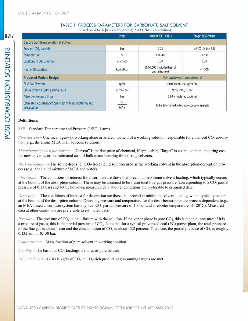
TABLE 1: PROCESS PARAMETERS FOR CARBONATE SALT SOLVENT(based on 40wt% [K2CO3
-equivalent] K2CO3/KHCO3 solution)
Units Current R&D Value Target R&D Value
Desorption (Lean Solution at Bottom)
Pressure (CO2 partial) bar 2-20 >7 (CO2/H2O > 3:1)
Temperature °C 130-200 <200
Equilibrium CO2 Loading mol/mol 0.20 0.20
Heat of Desorption kJ/mol CO2600-1,500 (included heat of
crystallization) <1,500
Proposed Module Design (for equipment developers)
Flue Gas Flowrate kg/hr 500,000 (100,000 kg/hr CO2)
CO2 Recovery, Purity, and Pressure % / % / bar 90%, 99%, 10 bar
Adsorber Pressure Drop bar 0.03 (structured packing)
Estimated Absorber/Stripper Cost of Manufacturing and Installation
$
kg/hr To be determined in techno-economic analysis
Definitions:
STP – Standard Temperature and Pressure (15°C, 1 atm).
Pure Solvent – Chemical agent(s), working alone or as a component of a working solution, responsible for enhanced CO2 absorp-tion (e.g., the amine MEA in an aqueous solution).
Manufacturing Cost for Solvent – “Current” is market price of chemical, if applicable; “Target” is estimated manufacturing cost for new solvents, or the estimated cost of bulk manufacturing for existing solvents.
Working Solution – The solute-free (i.e., CO2-free) liquid solution used as the working solvent in the absorption/desorption pro-cess (e.g., the liquid mixture of MEA and water).
Absorption – The conditions of interest for absorption are those that prevail at maximum solvent loading, which typically occurs at the bottom of the absorption column. These may be assumed to be 1 atm total flue-gas pressure (corresponding to a CO2 partial pressure of 0.13 bar) and 40°C; however, measured data at other conditions are preferable to estimated data.
Desorption – The conditions of interest for desorption are those that prevail at minimum solvent loading, which typically occurs at the bottom of the desorption column. Operating pressure and temperature for the desorber/stripper are process-dependent (e.g., an MEA-based absorption system has a typical CO2 partial pressure of 1.8 bar and a reboiler temperature of 120°C). Measured data at other conditions are preferable to estimated data.
Pressure – The pressure of CO2 in equilibrium with the solution. If the vapor phase is pure CO2, this is the total pressure; if it is a mixture of gases, this is the partial pressure of CO2. Note that for a typical pulverized coal (PC) power plant, the total pressure of the flue gas is about 1 atm and the concentration of CO2 is about 13.2 percent. Therefore, the partial pressure of CO2 is roughly 0.132 atm or 0.130 bar.
Concentration – Mass fraction of pure solvent in working solution.
Loading – The basis for CO2 loadings is moles of pure solvent.
Estimated Cost – Basis is kg/hr of CO2 in CO2-rich product gas; assuming targets are met.
B-242
POST
-CO
MBU
STIO
N S
OLV
ENTS
U.S. DEPARTMENT Of ENERGY
ADVANCED CARBON DIOXIDE CAPTURE R&D PROGRAM: TECHNOLOGY UPDATE, MAY 2013

Other Parameter Descriptions:
Chemical/Physical Solvent Mechanism – The overall reaction for CO2 absorption into potassium carbonate solution at 70-80°C is:
K2CO3+CO2+H2O=2KHCO3
The CO2-rich solution from the absorber is cooled to 30 to 35°C to crystallize KHCO3:
KHCO3 (aq) = KHCO3 (s)
The overall reaction for CO2 stripping using KHCO3 slurry at 140 to 200°C is:
2KHCO3 =K2CO3+CO2+H2O
Solvent Contaminant Resistance – K2CO3 reacts with the flue gas contaminants (e.g., SO2, nitrogen oxide [NOx], and hydrogen chloride [HCl]), to form K2SO4, KNO3, and KCl, resulting in solvent losses if the salts are not reclaimed.
Solvent Foaming Tendency – K2CO3/KHCO3 solution itself does not have a foaming problem. If an organic promoter is used, foaming may occur for the K2CO3/KHCO3 + promoter solution. However, the foaming tendency is expected to be less severe than the conventional amine-based processes because the promoter concentration is generally low.
Flue Gas Pretreatment Requirements – If an organic promoter is used, pretreatment of the flue gas is required to reduce the con-centration of SO2 to below 30 parts per million by volume (ppmv). If an inorganic promoter or a catalyst is used, flue gas pretreat-ment can be eliminated by a K2SO4 reclamation process under development in this project.
Solvent Make-Up Requirements – Stoichiometric loss of K2CO3 due to reactions with acidic gases in the flue gas (SO2, NOx, etc) is estimated 1.46 kg K2CO3/tonne CO2 captured based on the assumed 42 ppmv SO2 and 74 ppmv NOx in the flue gas exiting a wet flue gas desulfurization (FGD) unit.
If an organic promoter is used, the promoter has tendency to degrade. Since the promoter concentration is low and most of the promoter doesn’t enter the Hot-CAP stripping column, nominal losses due to promoter degradation is estimated to be about 10 percent of that in the conventional MEA-based processes.
Waste Streams Generated – Waste streams include sludge of inorganic salts (e.g., sulfate, nitrate, chloride, etc.) as a result of K2CO3/KHCO3 reactions with acid gases in the flue gas and liquid blowdown from the process to avoid accumulation of chlorine, metals, etc.
Process Design Concept:
figure 2: Process Design Concept
B-243
POST-C
OM
BUSTIO
N SO
LVENTS
APPENDIX B: CARBON DIOXIDE CAPTURE TECHNOLOGY SHEETS
NATIONAL ENERGY TECHNOLOGY LABORATORY

technology advantages
• High stripping pressure, which equates to low compression work and low stripping heat (high CO2/H2O ratio).
• Low sensible heat as a result of comparable working capacity to MEA and low Cp (1/2).
• Low heat of absorption – 7-17 kcal/mol CO2 (crystallization heat included) vs. 21 kcal/mol for MEA.
• Increased absorption rate by employing high concentration PC and high absorption temperature.
• FGD may be eliminated.
• No solvent degradation.
• Low-cost solvent.
• Less corrosiveness.
R&D challenges
• Identifying favorable process conditions and promoters/catalysts for achieving fast absorption kinetics in carbonate solution.
• Identifying process conditions and solution properties for achieving a fast crystallization rate and a desirable crystal size for solid separation.
• Identifying process conditions for potassium bicarbonate slurry to achieve stripping pressure ≥ 10 bar.
• Identifying process conditions for >95 percent SO2 removal and continuous reclamation of the sulfate.
• Identifying risk mitigation strategies to prevent fouling on surfaces of heat exchangers and crystallizers due to bicarbonate crystallization.
results to date/accomplishments
• Three inorganic catalysts and five amine and three amine acid salt promoters were evaluated using a batch stirred tank reac-tor.
• A bench-scale, packed-bed column was designed and fabricated to investigate the kinetics, mass transfer, and hydrodynamic performance of CO2 absorption in a packed-bed configuration. Absorption column tests revealed that CO2 removal efficiency by 40wt% K2CO3/KHCO3 solution promoted by either of two selected promoters at 70°C was higher than that of the counter-part 5M MEA solution at 50°C at the CO2 loading levels typical of the two processes.
• Mixed suspension-mixed product removal (MSMPR) crystallization tests revealed that pure KHCO3 crystals could be ob-tained and crystallization time ≤ 40 min was sufficient to obtain large crystal particles (>233 µm) required for efficient solid-liquid separation.
• Vapor Liquid Equilibrium (VLE) measurements for concentrated KHCO3/K2CO3 aqueous systems with high levels of K2CO3 conversion at temperatures of 140 to 200°C revealed the thermodynamic feasibility of high-pressure stripping (achieving both a high total pressure and a low H2O/CO2 pressure ratio).
• A bench-scale, packed-bed stripping column with a temperature rating of 200°C and pressure rating of 500 pounds per square inch absolute (psia) was fabricated and installed at the UIUC laboratory. Crystallization tests with sodium bicarbonate and potassium bicarbonate were completed and results revealed that crystallization of NaHCO3 from the mixture is feasible.
• Parametric tests of reclaiming the potassium sulfate desulfurization byproduct were performed and results provided guidance for developing a process concept for the combined SO2 removal and CO2 capture.
next steps
• Complete high-pressure stripping column test of K2CO3/KHCO3 system.
• Complete a techno-economic analysis for the Hot-CAP integrated with a 550-MWe power plant.
B-244
POST
-CO
MBU
STIO
N S
OLV
ENTS
U.S. DEPARTMENT Of ENERGY
ADVANCED CARBON DIOXIDE CAPTURE R&D PROGRAM: TECHNOLOGY UPDATE, MAY 2013

available reports/technical papers/presentations
Lu, Y., “Bench Scale Development of a Hot Carbonate Absorption Process with Crystallization-Enabled High Pressure Stripping for Post-Combustion CO2 Capture,” presented at the 2011 NETL CO2 Capture Technology Meeting, Pittsburgh, Pennsylvania, Au-gust 2011. http://www.netl.doe.gov/publications/proceedings/11/co2capture/presentations/2-Tuesday/23Aug11-Lu-ISGS-Hot%20Carbonate%20Absorption%20Process.pdf.
Lu, Y., “Bench Scale Development of a Hot Carbonate Absorption Process with Crystallization-Enabled High Pressure Stripping for Post-Combustion CO2 Capture,” presented at the 2012 NETL CO2 Capture Technology Meeting, Pittsburgh, Pennsylvania, July 2012. http://www.netl.doe.gov/publications/proceedings/12/co2capture/presentations/2-Tuesday/Y%20Lu-ISGS-Hot%20CAP.pdf.
Lu, Y.; O’Brien K.; and Chen, S., “Bench Scale Development of a Hot Carbonate Absorption Process with Crystallization-Ena-bled High Pressure Stripping for Post-Combustion CO2 Capture,” presented at the Project Review Meeting, Pittsburgh, PA, Febru-ary 15, 2013. http://www.netl.doe.gov/File%20Library/Research/Coal/ewr/co2/HotCAP-review-meeting-021513.pdf.
B-245
POST-C
OM
BUSTIO
N SO
LVENTS
APPENDIX B: CARBON DIOXIDE CAPTURE TECHNOLOGY SHEETS
NATIONAL ENERGY TECHNOLOGY LABORATORY

BENCH-SCALE SILICONE PROCESS fOR LOW-COST CO2 CAPTURE
primary project goals
GE Global Research is operating a post-combustion carbon dioxide (CO2) capture process using a novel aminosilicone-based solvent system (60wt/40wt GAP-1/TEG) capable of achieving 90 percent CO2 capture efficiency with less than a 35 percent increase in cost of electricity (COE).
technical goals
• Design and construct a bench-scale unit and obtain parametric data.
• Create a process model that more accurately predicts the capture efficiency and costs.
• Develop a material manufacturing plan for aminosilicone solvent.
• Develop a scale-up strategy.
technical content
GE will continue the development and testing of a novel aminosilicone-based solvent using a continuous bench-scale system to capture CO2 from simulated coal-fired flue gas. In a previous U.S. Department of Energy (DOE)-funded project (DE-NT0005310), the novel solvent was developed and tested in a laboratory-scale, continuous CO2-capturesystem.
The aminosilicone-based solvent has a much lower volatility than monoethanolamine (MEA), which simplifies the desorption process and decreases the energy required to affect CO2 desorption. The aminosilicone-based CO2-capture process is predicted to have a 34 percent lower energy penalty than a comparable MEA process. The solvent can be regener-ated at elevated pressures (≈5 atm), resulting in lower compression costs. Bench-scale tests will be used to update the COE calculations and perform a techno-economic feasibility study. Milliken/SiVance, LLC will study means for manufacturing the solvent in bench- and commercial-scale quantities, as well as methods for reducing the solvent cost (see Figure 1).
Previously measured experimental data from the laboratory-scale CO2-capture system have been used to design the continuous bench-scale system. Basic engineering data, such as mass-transfer information, will be obtained at the bench scale to determine process scal-ability and likely process economics. A manufacturing plan for the aminosilicone solvent and price model will be used for optimization of the solvent system. GE Global Research will operate the bench-scale system and gather the engineering and property data required to assess the technical and economic feasibility of the process. GE Energy is responsible for developing a model of the bench-scale process and calculating the COE, performing the technical and economic feasibility studies, and developing the scale-up strategy.
technology maturity:
Bench-Scale, Simulated flue Gas
project focus:
Novel Aminosilicone Solvent
participant:
GE Global Research
project number:
fE0007502
NETL project manager:
David [email protected]
principal investigator:
Benjamin WoodGE Global [email protected]
partners:
Milliken/SiVance LLCGE Energy
performance period:
10/1/11 – 12/31/13
B-246
POST
-CO
MBU
STIO
N S
OLV
ENTS
U.S. DEPARTMENT Of ENERGY
ADVANCED CARBON DIOXIDE CAPTURE R&D PROGRAM: TECHNOLOGY UPDATE, MAY 2013

figure 1: Summary of Program
TABLE 1: PROCESS PARAMETERSUnits Current R&D Value Target R&D Value
Pure Solvent
Molecular Weight mol-1 322.67 (amin)150.17 (TEG)
322.67 (amin)150.17 (TEG)
Normal Boiling Point °C 310 (amin)287 (TEG)
310 (amin)287 (TEG)
Normal Freezing Point °C -85 (amin)-7°C (TEG)
-85 (amin)-7°C (TEG)
Vapor Pressure @ 15°C bar 52 mm Hg @ 141°C (amin)<0.01 mm Hg @ 20°C (TEG)
52 mm Hg @ 141°C (amin)<0.01 mm Hg @ 20°C (TEG)
Manufacturing Cost for Solvent $/kg $160 $30
Working Solution
Concentration kg/kg 60/40 amin/TEG 60/40 amin/TEG
Specific Gravity (15°C/15°C) - 0.913 (amin) 1.124 (TEG)
0.913 (amin) 1.124 (TEG)
Specific Heat Capacity @ STP kJ/kg-K 43 43
Viscosity @ STP cP 4.37 (amin)49 (TEG)
4.37 (amin)49 (TEG)
Absorption
Pressure bar 1 1
Temperature °C 40-60 40-60
Equilibrium CO2 Loading mol/mol 0.51 0.83
Heat of Absorption kJ/mol CO2 106 106
Solution Viscosity cP 500 500
B-247
POST-C
OM
BUSTIO
N SO
LVENTS
APPENDIX B: CARBON DIOXIDE CAPTURE TECHNOLOGY SHEETS
NATIONAL ENERGY TECHNOLOGY LABORATORY

TABLE 1: PROCESS PARAMETERSUnits Current R&D Value Target R&D Value
Desorption
Pressure bar 1 6
Temperature °C 120°C 160°C
Equilibrium CO2 Loading mol/mol 0.05 0.25
Heat of Desorption kJ/mol CO2 -106 -106
Proposed Module Design (for equipment developers)
Flue Gas Flowrate kg/hr
CO2 Recovery, Purity, and Pressure % / % / bar
Adsorber Pressure Drop bar
Estimated Absorber/Stripper Cost of Manufacturing and Installation
$
kg/hr
* Working capacity is the loading difference of CO2-rich solution before and after it is regenerated.
Definitions:
STP – Standard Temperature and Pressure (15°C, 1 atm).
Pure Solvent – Chemical agent(s), working alone or as a component of a working solution, responsible for enhanced CO2 absorp-tion (e.g., the amine MEA in an aqueous solution).
Manufacturing Cost for Solvent – “Current” is market price of chemical, if applicable; “Target” is estimated manufacturing cost for new solvents, or the estimated cost of bulk manufacturing for existing solvents.
Working Solution – The solute-free (i.e., CO2-free) liquid solution used as the working solvent in the absorption/desorption pro-cess (e.g., the liquid mixture of MEA and water).
Absorption – The conditions of interest for absorption are those that prevail at maximum solvent loading, which typically occurs at the bottom of the absorption column. These may be assumed to be 1 atm total flue-gas pressure (corresponding to a CO2 partial pressure of 0.13 bar) and 40°C; however, measured data at other conditions are preferable to estimated data.
Desorption – The conditions of interest for desorption are those that prevail at minimum solvent loading, which typically occurs at the bottom of the desorption column. Operating pressure and temperature for the desorber/stripper are process-dependent (e.g., an MEA-based absorption system has a typical CO2 partial pressure of 1.8 bar and a reboiler temperature of 120°C). Measured data at other conditions are preferable to estimated data.
Pressure – The pressure of CO2 in equilibrium with the solution. If the vapor phase is pure CO2, this is the total pressure; if it is a mixture of gases, this is the partial pressure of CO2. Note that for a typical pulverized coal (PC) power plant, the total pressure of the flue gas is about 1 atm and the concentration of CO2 is about 13.2 percent. Therefore, the partial pressure of CO2 is roughly 0.132 atm or 0.130 bar.
Concentration – Mass fraction of pure solvent in working solution.
Loading – The basis for CO2 loadings is moles of pure solvent.
Estimated Cost – Basis is kg/hr of CO2 in CO2-rich product gas; assuming targets are met.
B-248
POST
-CO
MBU
STIO
N S
OLV
ENTS
U.S. DEPARTMENT Of ENERGY
ADVANCED CARBON DIOXIDE CAPTURE R&D PROGRAM: TECHNOLOGY UPDATE, MAY 2013

Other Parameter Descriptions:
Chemical/Physical Solvent Mechanism – The reaction of the GAP class of aminosilicones with CO2 is shown in Figure 2. The aminosilicone in this study is a mixture of GAP molecules where the average value of the subscript (x) shown in Figure 2 is 1. This solvent is designated GAP-1. GAP-1 is combined with triethylene glycol (TEG) in a 60/40 (by weight) mixture to inhibit the solidification that occurs when the neat solvent (GAP-1) reacts with CO2.
figure 2: Reaction of GAP Class of Aminosilicones with CO2 to form GAP Carbamate
Solvent Contaminant Resistance – As with MEA, aminosilicones will react irreversibly with sulfur dioxide (SO2) to form heat-stable salts (HSS). Solvent make-up will be required to replace aminosilicone lost to reaction with SO2.
Solvent Foaming Tendency – None observed.
Flue Gas Pretreatment Requirements – In a full-scale system, the flue gas pretreatment requirements are identical to those of an MEA-based process, including a selective catalytic reduction reactor, particulate removal, and flue gas desulfurizer (FGD).
Solvent Make-Up Requirements – In addition to the solvent make-up required due to reaction of aminosilicone with SO2, addition-al solvent make-up will be required due to thermal decomposition. However, it has been demonstrated that GAP-1 is significantly more thermally stable than MEA, as discussed below.
Waste Streams Generated – A waste stream of HSS from the reaction of SO2 with aminosilicone will be generated.
Process Design Concept – The process flow diagram for the aminosilicone-based, bench-scale CO2-capture system is shown in Figure 3.
figure 3: The Process flow Diagram for the Bench-Scale System
B-249
POST-C
OM
BUSTIO
N SO
LVENTS
APPENDIX B: CARBON DIOXIDE CAPTURE TECHNOLOGY SHEETS
NATIONAL ENERGY TECHNOLOGY LABORATORY

Proposed Module Design – Unless noted, flue gas feed pressure is 1.014 bara, temperature is 57°C, and composition leaving the flue gas desulfurization (FGD) unit (wet basis) should be assumed:
Composition (% vol) Composition (ppmv)CO2 H2O N2 O2 Ar SOx NOx
13.17 17.25 66.44 2.34 0.8 42 74
technology advantages
• High Thermal Stability – The aminosilicone-based solvent demonstrates high thermal stability, allowing the desorption to oc-cur at temperatures as high as 180°C. The higher desorption temperature results in increased desorption pressures with a high CO2 working capacity.
• Low Volatility – The low volatility of the aminosilicone-based solvent simplifies the CO2 desorption process, resulting in lower capital costs and less energy wasted on unwanted vaporization of the solvent.
• A 34 percent lower energy penalty than a comparable MEA process.
R&D challenges
• It may be necessary to reduce the water content of the flue gas prior to absorption to avoid water build-up in the solvent recir-culation loop, which may impose additional costs.
• The effects of water on solvent CO2 capacity, solvent degradation, and corrosion are unknown.
• Cost-effective scale-up of the process for producing aminosilicone solvent compared to current methods.
• Designing scaled-up unit mass- and heat-transfer operations that can significantly lower the COE with the higher viscosity and slower mass-transfer rates of the CO2-loaded solvent.
results to date/accomplishments
• Thermal stability tests (150 to 180°C for ≈90 days) results showed that the GAP-1/TEG solvent was stable at 150°C.
• Successfully completed the design and assembly of a continuous bench-scale absorption (flue gas flow rate up to 200 stand-ard liters/min [SLPM], 40°C)/desorption unit.
• Preliminary manufacturability analysis identified several improvements that could reduce the GAP-1 cost from the current cost of $150 to $160/kg to $45 to $85/kg.
next steps
• Complete bench-scale testing to determine scale-up effects and performance of aminosilicone-based solvent system.
• Develop model of bench-scale system performance and update COE calculations.
available reports/technical papers/presentations
Wood, B., “Bench-Scale Silicone Process for Low-Cost CO2 Capture,” presented at the 2012 NETL CO2 Capture Technology Meeting, July 2012. http://www.netl.doe.gov/publications/proceedings/12/co2capture/presentations/2-Tuesday/B%20Wood-GE-Silicone%20Process.pdf.
GE Global Research, 2011, Bench-Scale Silicone Process for Low-Cost CO2 Capture, Project kickoff meeting presentation, No-vember 22, 2011. http://www.netl.doe.gov/File%20Library/Research/Coal/ewr/co2/bench-scale-silicone-process-low-cost-kickoff-nov2011.pdf.
Perry, R.J., et.al, “Aminosilicones for CO2 Capture,” ChemSusChem, 2010, August 23,3(8): 919-930.
B-250
POST
-CO
MBU
STIO
N S
OLV
ENTS
U.S. DEPARTMENT Of ENERGY
ADVANCED CARBON DIOXIDE CAPTURE R&D PROGRAM: TECHNOLOGY UPDATE, MAY 2013

NOVEL SOLVENT SYSTEM fOR POST-COMBUSTION CO2 CAPTURE
primary project goals
The overall project goals are to demonstrate ION Engineering’s advanced solvent using a coal-fired, post-combustion pilot to obtain sufficient data to advance to the 0.5- to 1.0-meg-awatt (MW) slipstream level of testing and to demonstrate significant progress towards the achievement of U.S. Department of Energy (DOE) cost and performance targets for 2nd generation solvents.
technical goals
• Process design objectives are to evaluate key parameters for the design of a 1.0-gallon per minute (gpm) carbon dioxide (CO2) capture unit through laboratory work, process modeling, and performance tests.
• Process operation and evaluation objectives are to fabricate, install, and operate a bench-scale unit using simulated flue gas (CO2, nitrogen [N2], and water [H2O]) at ION’s laboratories.
• Test ION’s advanced solvent at the 0.2-MW scale using coal-fired flue gas at the En-ergy and Environmental Research Center’s (EERC) combustion test facility (CTF).
technical content
ION Engineering, in collaboration with its partners, will design, construct, operate, and evaluate a bench-scale CO2 capture system using simulated flue gas at ION’s laboratories. The project will demonstrate ION’s solvent approach for amine-based CO2 capture, using mixtures of amines and organic solvents. ION’s solvent system is related to well-understood aqueous amine solvent-based processes in that it utilizes proven amines as chemical sol-vents for CO2 capture; however, it differs significantly with the use of an organic solvent in place of water. By using an organic solvent in place of water, significant reductions in regeneration energy requirements and significantly higher CO2 loading capacities are antici-pated.
The project will demonstrate ION’s solvent system’s ability to capture CO2 using a 1.0-gpm bench-scale process unit, and will include simulation modeling to finalize process designs, laboratory evaluations, solvent selection, and scale-up from the existing laboratory units to the bench-scale process unit. The evaluation of ION’s solvent system using actual coal-fired flue gas will provide data for the design and operations for slipstream testing, as well as for the performance at commercial scale.
The project is divided into two phases. Phase I was focused on solvent thermophysical characterization, process simulation for coal-fired flue gas, and construction of the labora-tory pilot. Phase II has focused on testing ION’s advanced solvent in the laboratory pilot using several process configurations. Phase II has also included approximately 500 hours of testing using coal and natural gas combined cycle (NGCC) flue gas conditions at EERC’s CTF. Phase II further includes a techno-economic analyses conducted by EERC in order to obtain an estimate for the cost of electricity (COE) impact of ION’s advanced solvent for a new 550-MW coal-fired power generation facility.
technology maturity:
Pilot-scale, Actual flue Gas Slipstream (0.2 MW)
project focus:
Advanced Solvent
participant:
ION Engineering
project number:
fE0005799
NETL project manager:
Isaac [email protected]
principal investigator:
Alfred (Buz) Brown, PhDION Engineering, [email protected]
partners:
Electric Power Research InstituteEERCEltron ResearchUniversity of AlabamaWorleyParsons Group, Inc.
performance period:
10/1/10 – 9/30/13
B-251
POST-C
OM
BUSTIO
N SO
LVENTS
APPENDIX B: CARBON DIOXIDE CAPTURE TECHNOLOGY SHEETS
NATIONAL ENERGY TECHNOLOGY LABORATORY

figure 1: Coal-fired flue Gas Performance Summary for ION’s Advanced Solvent
figure 2: Block flow Diagram for Case 10 ION Advanced Solvent, PC Combustion Plant with CO2 Capture
B-252
POST
-CO
MBU
STIO
N S
OLV
ENTS
U.S. DEPARTMENT Of ENERGY
ADVANCED CARBON DIOXIDE CAPTURE R&D PROGRAM: TECHNOLOGY UPDATE, MAY 2013

TABLE 1: PROCESS PARAMETERS SOLVENTUnits Current R&D Value Target R&D Value
Pure Solvent
Molecular Weight mol-1 75 – 95 same
Normal Boiling Point °C 150 – 210 same
Normal Freezing Point °C -5.0 same
Vapor Pressure @ 15°C bar 1-2x10⁻⁴ same
Manufacturing Cost for Solvent $/kg N/A same
Working Solution
Concentration kg/kg 0.7 – 0.85 same
Specific Gravity (15°C/15°C) - ≈1.0 same
Specific Heat Capacity @ STP kJ/kg-K ≈2.0 same
Viscosity @ STP cP <5 same
Absorption
Pressure bar 0.10 – 0.15 same
Temperature °C 40 – 60 same
Equilibrium CO2 Loading mol/mol 1.1 – 1.7 1.75 – 2.5
Heat of Absorption kJ/mol CO2 1750 – 2000 same
Solution Viscosity cP < 20 same
Desorption
Pressure bar 1.1 same
Temperature °C 110 - 220 same
Equilibrium CO2 Loading mol/mol 0.017 – 0.417 0.01 – 0.2
Heat of Desorption kJ/mol CO2 1,750 – 2,000 same
Definitions:
STP – Standard Temperature and Pressure (15°C, 1 atm).
Pure Solvent – Chemical agent(s), working alone or as a component of a working solution, responsible for enhanced CO2 absorp-tion (e.g., the amine MEA in an aqueous solution).
Manufacturing Cost for Solvent – “Current” is market price of chemical, if applicable; “Target” is estimated manufacturing cost for new solvents, or the estimated cost of bulk manufacturing for existing solvents.
Working Solution – The solute-free (i.e., CO2-free) liquid solution used as the working solvent in the absorption/desorption pro-cess (e.g., the liquid mixture of MEA and water).
Absorption – The conditions of interest for absorption are those that prevail at maximum solvent loading, which typically occurs at the bottom of the absorption column. These may be assumed to be 1 atm total flue-gas pressure (corresponding to a CO2 partial pressure of 0.13 bar) and 40°C; however, measured data at other conditions are preferable to estimated data.
Desorption – The conditions of interest for desorption are those that prevail at minimum solvent loading, which typically occurs at the bottom of the desorption column. Operating pressure and temperature for the desorber/stripper are process-dependent (e.g., an MEA-based absorption system has a typical CO2 partial pressure of 1.8 bar and a reboiler temperature of 120°C). Measured data at other conditions are preferable to estimated data.
Pressure – The pressure of CO2 in equilibrium with the solution. If the vapor phase is pure CO2, this is the total pressure; if it is a mixture of gases, this is the partial pressure of CO2. Note that for a typical pulverized coal (PC) power plant, the total pressure of the flue gas is about 1 atm and the concentration of CO2 is about 13.2 percent. Therefore, the partial pressure of CO2 is roughly
B-253
POST-C
OM
BUSTIO
N SO
LVENTS
APPENDIX B: CARBON DIOXIDE CAPTURE TECHNOLOGY SHEETS
NATIONAL ENERGY TECHNOLOGY LABORATORY

0.132 atm or 0.130 bar.
Concentration – Mass fraction of pure solvent in working solution.
Loading – The basis for CO2 loadings is moles of pure solvent.
Estimated Cost – Basis is kg/hr of CO2 in CO2-rich product gas; assuming targets are met.
technology advantages
Relative to state-of-the-art aqueous amine technology, ION’s advanced solvent offers:
• Greater than 50 percent reduction in regeneration energy requirements, leading to lower operating and capital costs.
• Higher CO2 loading capacities, leading to lower operating and capital costs.
• Reduced corrosion and solvent losses.
• Less make-up water used by the process.
• Ability to use lower-quality steam in regeneration.
R&D challenges
• The current performance levels need to be demonstrated at the 0.5- to 1.0-MW slipstream level for longer test runs.
• Solvent stability, degradation, and corrosion potential needs to be investigated under coal-fired slipstream test conditions.
results to date/accomplishments
• Developed significant analytical and physical characterization capabilities to support further solvent development.
• Designed, constructed, and validated in-house lab pilot (9-gal/hr solvent flow and 180-standard liters per minute [SLPM] gas flow) for testing and characterization of ION advanced solvents.
• ION’s lead advanced solvent tested for more than 500 hours at EERC’s CTF under both coal and NGCC conditions.
• 72-h steady state test results indicate >50 percent reduction in regeneration energy and >35 percent decrease in L/G (improve-ment in CO2 carrying capacity) compared to aqueous monoethanolamine (MEA) (30 wt %).
• Techno-economic evaluation by EERC indicates:
- 37 percent increase in COE for new build @ 550 MW vs. 69 percent increase for MEA Case 10. - $27/ton CO2 capture cost (not avoided) vs. $45/ton for MEA Case 10 (not avoided). - 31.0 percent net plant efficiency vs. 26.2 percent net plant efficiency for MEA Case 10. - Reduced corrosion potential re aqueous MEA. - Significantly less make-up water re aqueous MEA.
next steps
• Complete evaluation of solvent degradation, loss, and corrosive potential at increasing concentrations of flue gas contami-nants.
• Complete technical and economic analyses.
• Complete final report for DOE.
available reports/technical papers/presentations
Pavlish, B.M.; Kay, J.P.; Strege, J.R.; Fiala, N.J.; Stanislowski, J.J.; Snyder, A.C. Subtask 2.5 – Partnership for CO2 Capture – Phases I and II; Final Report (Sept 1, 2010 – April 30, 2013) for U.S. Department of Energy National Energy Technology Laboratory Cooperative Agreement No. DE-FC26-08NT43291; EERC Publication 2013-EERC-04-12; Energy & Environmental Research Center: Grand Forks, ND, April 2013.
B-254
POST
-CO
MBU
STIO
N S
OLV
ENTS
U.S. DEPARTMENT Of ENERGY
ADVANCED CARBON DIOXIDE CAPTURE R&D PROGRAM: TECHNOLOGY UPDATE, MAY 2013

EVALUATION Of CONCENTRATED PIPERAZINE fOR CO2 CAPTURE fROM COAL-fIRED fLUE GAS
primary project goals
URS Group, Inc. (URS) is investigating the use of a high-temperature flash regenerator us-ing concentrated piperazine (PZ) solvent to capture carbon dioxide (CO2) from coal flue gas more economically. Pilot tests and analyses will be conducted at the 0.1-megawatt (MW) scale, and then scaled to the 0.5-MW scale for testing at the U.S. Department of Energy’s (DOE) National Carbon Capture Center (NCCC). Results will be used to evaluate the tech-nical and economic feasibility of a full-scale implementation of this process.
technical goals
Project objectives are to:
• Quantify and demonstrate the robustness of concentrated PZ with coal-fired flue gas in an integrated absorption/stripping system with solvent regeneration at 150°C.
• Optimize equipment design and energy performance of the innovative flash system.
• Identify and resolve other potential operational and design issues, including amine aerosol emissions, process control, corrosion, foaming, and solids precipitation.
technical content
URS, in collaboration with the University of Texas (UT) and Trimeric Corporation, will investigate the use of concentrated PZ as a solvent for absorbing CO2 from coal-fired power plant flue gas. Measured properties of PZ are shown in Table 1. Evaluations of concentrated PZ for CO2 removal have previously been performed through laboratory investigations, process modeling, and synthetic flue gas testing in a 0.1-MW unit. Results indicated greater than 90 percent CO2 capture with significant reduction in the cost of electricity (COE). This project continues the development of the PZ-based CO2 absorption process through a series of field tests to gain operational experience with the solvent in coal-fired flue gas, while employing a novel, high-temperature, two-stage flash (2SF) regeneration design.
The project team is conducting this project in two phases. In the first phase, the PZ absorp-tion process was combined with a novel regeneration scheme – a high-temperature 2SF, shown in Figure 1. A three-week test was conducted in synthetic flue gas at the 0.1-MW scale using PZ in the absorption column at UT’s Separations Research Program (SRP) plant, coupled with the project team’s 0.1-MW 2SF system. The results from the SRP test program and the techno-economic analysis demonstrated the benefits of using PZ as a solvent-of-choice for CO2 capture. The results from the SRP test program demonstrated that 2SF regeneration is a viable alternative regeneration process to simple stripping; however, the techno-economic analysis showed only a marginal economic benefit of the 2SF process.
Based on the project findings thus far, the project team recommended to DOE’s National Energy Technology Laboratory (NETL) that the 2SF regeneration process not be scaled-up for a test campaign at NCCC. Since one of the main objectives of this project is to address operational and design issues of the PZ process, the project team recommended to DOE/
technology maturity:
Pilot-Scale, Simulated flue Gas and Actual flue Gas Slipstream
project focus:
Piperazine Solvent with flash Regeneration
participant:
URS Group
project number:
fE0005654
NETL project manager:
Bruce [email protected]
principal investigator:
Katherine DombrowskiURS Group, [email protected]
partners:
Trimeric CorporationUniversity of Texas (UT) at Austin
performance period:
10/1/10 – 9/30/13
B-255
POST-C
OM
BUSTIO
N SO
LVENTS
APPENDIX B: CARBON DIOXIDE CAPTURE TECHNOLOGY SHEETS
NATIONAL ENERGY TECHNOLOGY LABORATORY

NETL that project resources be allocated towards investigating and solving critical solvent management issues that are common to amine solvents, including PZ. DOE/NETL approved the project team to use the project resources remaining in Phase I to study aerosol formation in the absorber. Aerosols have been implicated in high amine emissions from absorbers at several pilot plants. The project team will conduct tests at UT’s SRP plant to investigate possible mechanisms for aerosol formation; these tests are planned for 2013. After completion of the aerosol tests at the SRP plant, the project team will submit a continuation application to DOE/NETL to proceed to Phase II, in which PZ will be tested at the 0.5-MW scale on coal-fired flue gas at NCCC.
figure 1: Diagram of PZ CO2 Absorption Process with High-Temperature Two-Stage flash
TABLE 1: PROCESS PARAMETERS FOR 8 MOLAL PIPERAZINE SOLVENTUnits Current R&D Value
Pure Solvent
Molecular Weight mol-1 86.14
Normal Boiling Point °C 146
Normal Freezing Point °C 106
Vapor Pressure @ 15°C bar 0.000206
Manufacturing Cost for Solvent $/kg $60/lb eq N
Working Solution
Concentration kg/kg 40.79%
Specific Gravity (15°C/15°C) - 1.029
Specific Heat Capacity @ STP kJ/kg-K 3.197
Viscosity @ STP cP 17.7
Absorption
Pressure bar 0.05
Temperature °C 40
Equilibrium CO2 Loading mol/mol 0.8
Heat of Absorption kJ/mol CO2 70
Solution Viscosity cP 11.5
Desorption
Pressure bar 6
Temperature °C 150
Equilibrium CO2 Loading mol/mol 0.3
Heat of Desorption kJ/mol CO2 70
B-256
POST
-CO
MBU
STIO
N S
OLV
ENTS
U.S. DEPARTMENT Of ENERGY
ADVANCED CARBON DIOXIDE CAPTURE R&D PROGRAM: TECHNOLOGY UPDATE, MAY 2013
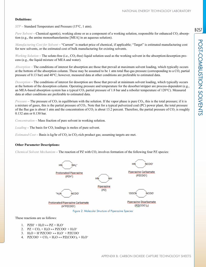
Definitions:
STP – Standard Temperature and Pressure (15°C, 1 atm).
Pure Solvent – Chemical agent(s), working alone or as a component of a working solution, responsible for enhanced CO2 absorp-tion (e.g., the amine monoethanolamine [MEA] in an aqueous solution).
Manufacturing Cost for Solvent – “Current” is market price of chemical, if applicable; “Target” is estimated manufacturing cost for new solvents, or the estimated cost of bulk manufacturing for existing solvents.
Working Solution – The solute-free (i.e., CO2-free) liquid solution used as the working solvent in the absorption/desorption pro-cess (e.g., the liquid mixture of MEA and water).
Absorption – The conditions of interest for absorption are those that prevail at maximum solvent loading, which typically occurs at the bottom of the absorption column. These may be assumed to be 1 atm total flue-gas pressure (corresponding to a CO2 partial pressure of 0.13 bar) and 40°C; however, measured data at other conditions are preferable to estimated data.
Desorption – The conditions of interest for desorption are those that prevail at minimum solvent loading, which typically occurs at the bottom of the desorption column. Operating pressure and temperature for the desorber/stripper are process-dependent (e.g., an MEA-based absorption system has a typical CO2 partial pressure of 1.8 bar and a reboiler temperature of 120°C). Measured data at other conditions are preferable to estimated data.
Pressure – The pressure of CO2 in equilibrium with the solution. If the vapor phase is pure CO2, this is the total pressure; if it is a mixture of gases, this is the partial pressure of CO2. Note that for a typical pulverized coal (PC) power plant, the total pressure of the flue gas is about 1 atm and the concentration of CO2 is about 13.2 percent. Therefore, the partial pressure of CO2 is roughly 0.132 atm or 0.130 bar.
Concentration – Mass fraction of pure solvent in working solution.
Loading – The basis for CO2 loadings is moles of pure solvent.
Estimated Cost – Basis is kg/hr of CO2 in CO2-rich product gas; assuming targets are met.
Other Parameter Descriptions:
Chemical Solvent Mechanism – The reaction of PZ with CO2 involves formation of the following four PZ species:
figure 2: Molecular Structure of Piperazine Species1
These reactions are as follows:
1. PZH+ + H2O ↔ PZ + H3O+
2. PZ + CO2 + H2O ↔ PZCOO- + H3O+
3. H2O + H+PZCOO- ↔ H3O+ + PZCOO-
4. PZCOO- + CO2 + H2O ↔ PZ(COO-)2 + H3O+
B-257
POST-C
OM
BUSTIO
N SO
LVENTS
APPENDIX B: CARBON DIOXIDE CAPTURE TECHNOLOGY SHEETS
NATIONAL ENERGY TECHNOLOGY LABORATORY

TABLE 2: EQUILIBRIUM CONSTANTS FOR ABOVE REACTIONS1
Eq. No. Equilibrium Constantln K = A + B/T + C lnT
A B C
1 -11.91 -4,351 –
2 -29.31 5,615 –
3 -8.21 -5,286 –
4 -30.78 5,615 –
This speciation and solubility model has been used to predict the partial pressure of CO2 and mole fraction of species in solution as a function of PZ loading; the results show a good match between the model and the experimental data.
Solvent Contaminant Resistance – 8-m PZ is thermally stable at 150°C with negligible oxidative (Freeman, 2011) degradation. The total amine loss is estimated to be 0.5 percent per week when stripping at 150°C. At 135°C, the estimated total amine loss of PZ is 0.3 percent as compared to 3.0 percent in the case of an MEA solvent. PZ forms nitrosamines and other nitro products with nitrogen dioxide (NO2). Both pilot-scale flue gas testing and bench-scale testing have confirmed that nitrosamines decompose at temperatures of 150°C and greater. The main degradation products of PZ are formate (0.04 mM/hr) and ammonia (0.09 mM/hr) (Freeman, 2011).
Solvent Foaming Tendency – Pilot plant tests of PZ with two different sources of coal-fired flue gas and with air/CO2 have expe-rienced no problems with foaming. However, bench-scale experiments have shown the possibility for PZ to foam under certain conditions (e.g., after undergoing oxidation degradation). In the bench-scale tests, foaming of PZ was greatly reduced with use of an oxidation inhibitor or with use of 1 part per million (ppm) of silicone antifoam (Chen, 2011).
Flue Gas Pretreatment Requirement – Tests at UT’s SRP plant were performed on synthetic flue gas composed of air and CO2. NCCC tests will be conducted on medium-sulfur bituminous coal flue gas cleaned by flue gas desulfurization (FGD). Commercial applications would likely need sulfur oxides (SOx) to be removed to levels below 10 ppm.
Solvent Make-Up Requirements – Including an estimate for additional amine lost in the reclaiming process, the required make-up rate is estimated to be 0.76 kg of 40 wt% PZ per metric ton of CO2 captured for PZ regenerated at 150°C. The estimated make-up rate for 30 wt% MEA at 120°C is approximately 2.0 kg/MT CO2.
Waste Streams Generated – The major amine solid/liquid waste streams come from reclaimer waste. There could be fugitive liquid amine emissions, which can be controlled by incorporating seamless valves, rupture disks, closed-loop ventilation systems, pumps with dual mechanical seals, minimum welds, and correct gasket material selection. Gas-phase amine emissions from the absorber can be minimized by controlling aerosol formation and aerosol emissions from the absorber. Gas-phase amine emissions from the stripper can be minimized by controlling temperature of the CO2 outlet gas and via operating conditions of the condenser.
Process Design Concept – Flowsheet/block flow diagram shown above.
B-258
POST
-CO
MBU
STIO
N S
OLV
ENTS
U.S. DEPARTMENT Of ENERGY
ADVANCED CARBON DIOXIDE CAPTURE R&D PROGRAM: TECHNOLOGY UPDATE, MAY 2013

Proposed Module Design – Unless noted, flue gas feed pressure is 1.014 bara, temperature is 57°C, and composition leaving the flue gas desulfurization (FGD) unit (wet basis) should be assumed:
Composition (% vol) Composition (ppmv)CO2 H2O N2 O2 Ar SOx NOx
13.17 17.25 66.44 2.34 0.8 42 74
technology advantages
As compared to conventional amine solvents, the advantages of PZ are:
• Faster CO2 absorption rate, higher working capacity, higher thermal stability, and less oxidative degradation – all of which point toward 10 to 20 percent less energy use.
• Lower capital costs due to reduced energy use, greater stripper pressure (reduced compressor size), and faster kinetics.
• Additional savings in COE may be achieved by optimization of absorber packing, flue gas pre-treating, compressors, heat exchangers, and design improvements realized as part of this project
R&D challenges
• Similar to other amines, PZ may absorb on aerosols in flue gas leading to poor amine collection in the water wash after CO2 absorption and thus high amine emissions.
• PZ reacts with dissolved or entrained oxygen (O2) at temperatures exceeding 150°C, potentially leading to greater than ex-pected solvent makeup, but still less than MEA. Techniques to reduce oxidative degradation, including sparging with N2, or flashing at T < 100°C are being investigated.
• Robustness of concentrated PZ in flue gas and thermal reclaiming of degraded solvent needs to be demonstrated, because PZ is more expensive to replace than MEA.
• PZ forms as a solid phase with water (PZ·6H2O) and also with CO2 (H+PZCOO-·H2O). Process robustness to excursions in CO2 loading, temperature, and water balance is being demonstrated by quantifying their effects on solids precipitation and plant operation.
results to date/accomplishments
• UT-SRP tests demonstrated integration of a high-temperature 2SF (13.5 atm, 8 atm) stripping process with low-thermal deg-radation, and quantified mass transfer and energy performance with 8-m PZ.
• Operating conditions for 90 percent CO2 removal (0.31 lean loading, 0.41 rich loading) with high-temperature PZ regenera-tion were identified.
• The CO2 removal rate was improved by 6 to 7 percent with spray intercooling in the absorber during the 0.1-MW test cam-paign at UT SRP.
• Minimal solids precipitation was observed in steady-state operation.
• Process analyses indicated that the high-temperature 2SF process increased the COE by 62.6 percent compared to 81.7 per-cent increase for MEA. The energy consumption was lowered to 230 kWh/T CO2.
• Process analysis showed that purchased equipment costs for capture and compression were reduced for the PZ high-temper-ature 2SF process versus PZ with a simple stripper, but the simple stripper process had slightly better energy performance; these two effects essentially canceled each other out in terms of impact on COE.
B-259
POST-C
OM
BUSTIO
N SO
LVENTS
APPENDIX B: CARBON DIOXIDE CAPTURE TECHNOLOGY SHEETS
NATIONAL ENERGY TECHNOLOGY LABORATORY

next steps
• Further tests (during NCCC 0.5-MW testing) are needed to demonstrate reliable operation on coal-fired flue gas and during longer-term operation in which excursions of CO2 loading, temperature, and water balance are encountered.
• Solvent degradation in coal-fired flue gas and methods to reduce oxidative solvent degradation will be evaluated during NCCC tests.
• PZ aerosol mitigation technologies (DOE scope) will be tested alongside the next generation advanced flash stripper configu-ration (non-DOE scope) at the SRP pilot plant in 2013. The purpose of the DOE-funded tests is to demonstrate mechanisms for aerosol growth and aerosol capture strategies. The purpose of the non-DOE scope is to demonstrate improved energy per-formance of the advanced flash stripper configuration at SRP, so as to provide an advanced regeneration technology for use in DOE-funded Phase II PZ tests at NCCC. Process models results indicate that the equivalent work for the advanced flash stripper configuration is 30.3 kJ/mol CO2 as compared to 31.5 kJ/mol CO2 for the 2SF (Madan, 2013).
available reports/technical papers/presentations
Rochelle, G., “Pilot Plant Testing of Piperazine with High T Regeneration,” presented at the 2012 NETL CO2 Capture Tech-nology Meeting, Pittsburgh, PA, July 2012. Available at: http://www.netl.doe.gov/publications/proceedings/12/co2capture/presentations/2-Tuesday/G%20Rochelle-UT%20Austin-Piperazine.pdf.
Freeman, S.A., 2011, Thermal degradation and oxidation of aqueous piperazine for carbon dioxide capture, Ph.D. Thesis, Univer-sity of Texas at Austin. Available at: http://repositories.lib.utexas.edu/handle/2152/ETD-UT-2011-05-3290.
Sexton, A., “Evaluation of Concentrated Piperazine for CO2 Capture from Coal-Fired Flue Gas,” presented at the 2011 NETL CO2 Capture Technology Meeting, Pittsburgh, PA, August 2011. Available at: http://www.netl.doe.gov/publications/proceedings/11/co-2capture/presentations/2-Tuesday/23Aug11-Sexton-Trimeric-Concentrated%20Piperazine%20for%20CO2%20Capt.pdf.
Dombrowski, K., “Evaluation of Concentrated Piperazine for CO2 Capture from Coal-Fired Flue Gas,” presented at the 2010 NETL CO2 Capture Technology Meeting, Pittsburgh, PA, September 2010. Available at: http://www.netl.doe.gov/publications/pro-ceedings/10/co2capture/presentations/wednesday/Katherine%20Dombrowski%20-%20URS%20Corporation.pdf.
Fine, N. A.; Goldman, M. J.; Nielsen, P. T.; Rochelle, G. T. Managing N-nitrosopiperazine and Dinitrosopiperazine, presented at GHGT-11 Kyoto, Japan. November 18-22, 2012. Energy Procedia, 2013.
Fulk, S. M.; Rochelle, G. T. Modeling Aerosols in Amine-Based CO2 Capture. GHGT-11; Energy Proc. 2013.
Madan, T.; Stripper Configurations and Modeling for CO2 Capture Using Piperazine. M. S. Thesis. The University of Texas at Austin, May 2013.
Nielsen, P. T.; Li, L.; Rochelle, G. T. Piperazine Degradation in Pilot Plants. GHGT-11; Energy Proc. 2013.
B-260
POST
-CO
MBU
STIO
N S
OLV
ENTS
U.S. DEPARTMENT Of ENERGY
ADVANCED CARBON DIOXIDE CAPTURE R&D PROGRAM: TECHNOLOGY UPDATE, MAY 2013

ADVANCED LOW-ENERGY, ENZYME-CATALYZED SOLVENT fOR CO2 CAPTURE
primary project goals
Akermin is developing a bench-scale system to capture up to 90 percent of carbon dioxide (CO2) from a flue gas stream using a solvent with lower parasitic energy using an im-mobilized enzyme, carbonic anhydrase (CA) that catalyzes the hydration reaction of CO2 into bicarbonate in solution. Project objectives include the demonstration of a CA delivery system to improve absorption kinetics and to decrease system costs, and advancing the development by bench-scale tests with coal-derived flue gas at the National Carbon Capture Center (NCCC).
technical goals
• Evaluate potential enzyme sources for stability under anticipated operating conditions and down-select to preferred option.
• Optimize design of proprietary polymer films to achieve efficient enzyme immobiliza-tion and stabilization.
• Develop detailed Aspen model of enzyme-catalyzed carbonate system and extrapolate to a power plant scale of 550 MWe net; outputs include mass and energy balance, elec-tric power requirements, and projected chemical and maintenance costs.
• Build and test a closed-loop, bench-scale pilot plant capable of processing up to 500 standard liters per minute (SLPM) of flue gas, the approximate equivalent of a 5- to 7-kWe power plant, and demonstrate continuous operation for up to six months.
technical content
An enzyme-catalyzed, low-energy solvent system is being developed for post-combustion CO2 capture in this project. The core technology involves the integration of a proprietary immobilized-CA enzyme into a packed column absorber to promote the hydration of CO2 in lower-reaction energy solvents. Chemical solvents of interest include potassium carbonate (K2CO3) salt solution. The principal project objective is to demonstrate 90 percent CO2 cap-ture from coal-derived flue gas in a bench-scale unit with absorption rates competitive with amine-based solvents using a salt solution that has significantly lower regeneration energy and is non-volatile, stable towards oxidation, and environmentally safer. Other key project objectives include evaluating the potential impact of minor contaminants (such as sulfur oxides [SOx] and nitrogen oxides [NOx] common to coal-derived flue gases) using lab- and bench-scale tests and to demonstrate immobilized-enzyme activity in excess of 200 days in a continuous, closed-loop reactor (CLR) unit.
The current work plan is focused on establishing kinetic and lab-scale CLR data to support design and scale-up from lab-scale ≈4 SLPM to the bench-unit scale ≈500 SLPM flue gas. Akermin is working to identify a preferred strain of CA that will have a long lifetime under industrial conditions to optimize a delivery system and scale-up to a bench-scale integrated system.
technology maturity:
Bench-Scale, Actual flue Gas Slipstream
project focus:
Carbonic Anhydrase-Potassium Carbonate Mixture
participant:
Akermin
project number:
fE0004228
NETL project manager:
Andrew [email protected]
principal investigator:
John ReardonAkermin, [email protected]
partners:
Battelle Memorial Institute (Battelle)Pacific Northwest National Laboratory (PNNL)
performance period:
10/1/10 – 6/30/13
B-261
POST-C
OM
BUSTIO
N SO
LVENTS
APPENDIX B: CARBON DIOXIDE CAPTURE TECHNOLOGY SHEETS
NATIONAL ENERGY TECHNOLOGY LABORATORY

Pacific Northwest National Laboratory (PNNL) and Battelle Memorial Institute (Battelle) are collaborating to perform necessary wetted-wall kinetic and mass-transfer studies, process modeling, and relevant cost estimation to determine how such a system would scale and cost-effectively integrate into an existing coal-fired power plant compared to the U.S. Department of Energy’s (DOE) goal of less than a 35 percent increase in cost of electricity (COE) with post-combustion CO2 capture.
figure 1: Akermin’s CO2 Capture Process
The four main areas of development in this project include: identification of preferred enzyme; optimization of biocatalyst delivery system; definition of operating limits (using lab-scale reactor data and process modeling); and performing process design, system engineering, fabrication, and commissioning of a bench-scale unit. The integrated bench-scale system will be capable of processing simulated flue gas or interfacing directly to a commercial flue gas slip-stream. The bench-scale absorber contains commercial packing coated with immobilized enzyme.
TABLE 1: PROCESS PARAMETERS SOLVENTUnits Current R&D Value Target R&D Value
Pure Solvent
Molecular Weight mol-1 138.2 N/A
Normal Boiling Point °C 103.7 N/A
Normal Freezing Point °C -3.7 N/A
Vapor Pressure @ 15°C bar Non-Volatile N/A
Manufacturing Cost for Solvent $/kg solution $0.42 $0.37
Working Solution
Concentration kg K2CO3/ kg soln. 0.20 0.20
Specific Gravity (15°C/15°C) - 1.19 N/A
Specific Heat Capacity @ STP kJ/kg-K 3.54 N/A
Viscosity @ STP cP 1.95 N/A
Absorption
Pressure bar 1.07 1.07
Temperature °C 40 N/A
B-262
POST
-CO
MBU
STIO
N S
OLV
ENTS
U.S. DEPARTMENT Of ENERGY
ADVANCED CARBON DIOXIDE CAPTURE R&D PROGRAM: TECHNOLOGY UPDATE, MAY 2013

TABLE 1: PROCESS PARAMETERS SOLVENTUnits Current R&D Value Target R&D Value
Equilibrium CO2 Loading mol/mol K2CO3 0.7 0.8
Heat of Absorption kJ/mol CO2 28.2 N/A
Solution Viscosity cP 1.32 1.3
Desorption
Pressure bar 1.1 0.5
Temperature °C 106.3 70
Equilibrium CO2 Loading mol CO2/mol K2CO3 0.3 (as regenerated) 0.3
Heat of Desorption kJ/mol CO2 28.2 N/A
Proposed Module Design (for equipment developers)
Flue Gas Flowrate kg/hr 2,850,000 kg/hr (saturated)520,000 kg/hr CO2 captured
CO2 Recovery, Purity, and Pressure % / % / bar 90%, >99%, 1 bar
Adsorber Pressure Drop bar 0.04
Estimated Absorber/Stripper Cost of Manufacturing and Installation
$
kg/hr $1,000 / kg/hr CO2 captured
Definitions:
STP – Standard Temperature and Pressure (15°C, 1 atm).
Pure Solvent – Chemical agent(s), working alone or as a component of a working solution, responsible for enhanced CO2 absorp-tion (e.g., the amine MEA in an aqueous solution). In this particular case, K2CO3 does not react directly with CO2 and is therefore not a solvent per se, rather it is an environmentally benign, non-toxic salt solution that provides carrying capacity by serving as a proton acceptor supporting the reaction between CO2 and H2O (water).
Manufacturing Cost for Solvent – “Current” is market price of chemical, if applicable; “Target” is estimated manufacturing cost for new solvents, or the estimated cost of bulk manufacturing for existing solvents.
Working Solution – The solute-free (i.e., CO2-free) liquid solution used as the working solvent in the absorption/desorption pro-cess (e.g., the liquid mixture of MEA and water).
Absorption – The conditions of interest for absorption are those that prevail at maximum solvent loading, which typically occurs at the bottom of the absorption column. These may be assumed to be 1-atm total flue-gas pressure (corresponding to a CO2 partial pressure of 0.13 bar) and 40°C; however, measured data at other conditions are preferable to estimated data.
Desorption – The conditions of interest for desorption are those that prevail at minimum solvent loading, which typically occurs at the bottom of the desorption column. Operating pressure and temperature for the desorber/stripper are process-dependent (e.g., an MEA-based absorption system has a typical CO2 partial pressure of 1.8 bar and a reboiler temperature of 120°C). Measured data at other conditions are preferable to estimated data.
Pressure – The pressure of CO2 in equilibrium with the solution. If the vapor phase is pure CO2, this is the total pressure; if it is a mixture of gases, this is the partial pressure of CO2. Note that for a typical pulverized coal (PC) power plant, the total pressure of the flue gas is about 1 atm and the concentration of CO2 is about 13.2 percent. Therefore, the partial pressure of CO2 is roughly 0.132 atm or 0.130 bar.
Concentration – Mass fraction of pure solvent in working solution.
Loading – The basis for CO2 loadings is moles of pure solvent.
Estimated Cost – Basis is kg/hr of CO2 in CO2-rich product gas; assuming targets are met.
B-263
POST-C
OM
BUSTIO
N SO
LVENTS
APPENDIX B: CARBON DIOXIDE CAPTURE TECHNOLOGY SHEETS
NATIONAL ENERGY TECHNOLOGY LABORATORY

Other Parameter Descriptions:
Chemical Solvent Mechanism – The reaction of water (H2O) with CO2 in the presence of CA in aqueous K2CO3 salt solution is as follows:
1. H2O + CO2 ↔ HCO3- + H+
2. H+ + CO3= ↔ HCO3
-
3. K2CO3(aq) → 2K+ + CO3=
4. Overall: H2O + CO2 + K2CO3(aq) ↔ 2KHCO3 ΔH° = 640 kJ/kg CO2
The presence of CA increases the rate of conversion of CO2 to bicarbonate, but does not affect the equilibrium yield of the reac-tion. The rate of reaction of H2O with CO2 in the absence of the enzyme is exceedingly slow, but the enzyme hydrates CO2 on the order of micro-seconds (kcat = ≈1/micro-second) and is limited only by diffusion.
Solvent Contaminant Resistance – Studies with K2CO3 and CA in solution indicate that the enzyme is not inhibited by sulfate, sulfite, nitrite, nitrate, or chloride ions in solution at levels expected for coal flue gas. Divalent metal ions (mercury [Hg2+], lead [Pb2+]) inhibit the activity of soluble CA because the active site in the enzyme itself contains a divalent metal ion (mainly zinc). However, the immobilization and the low solubility of their hydroxide and carbonate salts in carbonate solutions may alleviate some of the decrease in CA activity at high pH.
Solvent Foaming Tendency – The presence of soluble enzyme can contribute to foaming, especially in the stripper, whereas the tendency to foam is mitigated by using immobilized enzyme, retaining enzyme in the absorber and part per million (ppm) quanti-ties of anti-foams.
Flue Gas Pretreatment Requirement – Acid gases do not impact the solvent CO2 capacity significantly; however, mercury emis-sions may need to be controlled to avoid loss of CA activity.
Solvent Make-up Requirements – The capture of acid gases such as sulfur dioxide (SO2) and nitrogen dioxide (NO2) will reduce carrying capacity over time. Initial tests indicate the loss of capacity to be on the order of 2 percent per year or less. K2CO3 is non-volatile and has excellent oxidative stability (an inorganic salt solution); therefore, mainly water make-up is required.
Waste Streams Generated – Deactivated packing would need to be replaced to maintain CA activity on an ongoing basis. Any solids salts precipitated in carbonate solutions need to be separated and disposed appropriately.
Process Design Concept – Figure 1 presents the basic process flow sheet.
Proposed Module Design – Unless noted, flue gas feed pressure is 1.014 bara, temperature is 57°C, and composition leaving the flue gas desulfurization (FGD) unit (wet basis) should be assumed:
Composition (% vol) Composition (ppmv)CO2 H2O N2 O2 Ar SOx NOx
13.17 17.25 66.44 2.34 0.8 42 74
technology advantages
• Ability to capture 90 percent CO2 with absorption rates competitive with amine-based solvents using an inorganic salt solu-tion that has significantly lower regeneration energy, as well as being non-volatile, oxidative stable, and environmentally benign.
• K2CO3 is non-volatile and stable compared to amine solvents; the non-volatile and stable features of K2CO3 eliminate the capital costs for the water wash for polishing units to minimize impurities (SOx, NOx) that accelerate degradation of amine solvents and for amine re-claimer systems.
• K2CO3 solutions can be regenerated with low-grade steam due to lower regeneration temperatures; therefore, more power can be generated resulting in lower auxiliary power requirements, lower unit capital costs, and lower CO2 capture costs.
B-264
POST
-CO
MBU
STIO
N S
OLV
ENTS
U.S. DEPARTMENT Of ENERGY
ADVANCED CARBON DIOXIDE CAPTURE R&D PROGRAM: TECHNOLOGY UPDATE, MAY 2013

R&D challenges
• Flexible immobilization technology needed, which can scale-up and is adaptable to varied carbonate chemistries (K2CO3/KHCO3, ammonium carbonate, methyldiethanolamine [MDEA], etc.).
• Improved understanding of costs, optimized column, and energy performance is required from process design and scale-up studies due to the unique nature of the absorber with three-phase heterogeneous catalysis.
• Improved scalable immobilized catalyst production processes to achieve consistent, long-term performance.
results to date/accomplishments
• Demonstrated >87 percent physical protein (CA) retention at absorber conditions with the silica-based sol-gel immobilization technology after 100 hours of testing.
• Demonstrated a 22x improvement in the rate of mass transfer with immobilized enzyme coated on ceramic spheres in a packed column CLR, suggesting good potential to lower absorber heights and reduced capital costs.
• Completed a 200-day endurance test of the immobilized CA enzyme in 20 wt% K2CO3 solution with pH 10, 45°C, and a gas flow rate of 400 ml/min (standard) and a liquid flow rate of 20 ml/min. The initial enhancement in activity was 12x, which declined by 54 percent over the 240-day test period.
• In lab-scale testing with sub-bituminous coal flue gas containing SOx, NOx, and Hg (20 ppm SO2, 20 ppm NO2, and 2 parts per billion by weight [ppbw] Hg), 90 to 95 percent CO2 capture was achieved and sustained for 23 days using a packed-col-umn absorber containing packing with immobilized CA.
• Modeling calculations show a 16x improvement in the rate of CO2 absorption by the presence of immobilized CA, which would significantly lower the height of a CO2 absorber operating on K2CO3 from ≈1,300 feet to 80 feet.
• Techno-economic analyses indicate that the regeneration energy could approach 3,200 kJ/kg CO2; however, a significant reduction in parasitic power was achieved by using low-grade steam that resulted in lower-net capital costs. The incremental COE over a plant without CO2 capture varied from 68 to 63 percent depending on assumptions.
next steps
• A bench-scale test unit (500 SLPM flue gas, 300 kg 20 percent K2CO3/h) was installed, commissioned, and initially tested without the biocatalyst in January 2013. Next steps include testing the bench unit with biocatalyst beginning in May 2013.
• The bench-scale test unit will be operated at NCCC through the end of the project period.
• The capital and operational cost estimates for the full-scale, coal-fired power plant would be revised by June 2013, based on results from bench-scale testing.
available reports/technical papers/presentations
Zaks, A., “Advanced Low Energy Enzyme Catalyzed Solvent for CO2 Capture,” presented at the 2011 NETL Annual CO2 Capture Technology Meeting, August, 2011, Pittsburgh, PA.
Zaks, A., “Advanced Enzyme-Catalyzed CO2 Capture in Low-Energy Solvents,” presented at the 2012 NETL Annual CO2 Cap-ture Technology Meeting, July, 2012, Pittsburgh, PA.
Black, S., et al., “Enzyme-Catalyzed Process for Low-Cost CO2 Separation and Capture,” presented at the 2012 MEGA Confer-ence, August, 2012, Baltimore, MD.
B-265
POST-C
OM
BUSTIO
N SO
LVENTS
APPENDIX B: CARBON DIOXIDE CAPTURE TECHNOLOGY SHEETS
NATIONAL ENERGY TECHNOLOGY LABORATORY

DEVELOPMENT Of CHEMICAL ADDITIVES fOR CO2 CAPTURE COST REDUCTION
primary project goals
Lawrence Berkeley National Laboratory (LBNL) will investigate a novel mixed solvent system that will integrate amine-based and ammonia-based solvents to provide benefits of both systems while avoiding many of their drawbacks.
technical goals
• Develop chemical additives that will reduce the cost of post-combustion capture of carbon dioxide (CO2) in solvent-based systems.
• Determine the optimal process configuration and operating condition for the transfer of CO2 in amine solvent to potassium bicarbonate (KHCO3), and then to an ammonium species, resulting in the production of NH4HCO3.
technical content
The new solvent system uses a novel solvent transfer approach after the capture of CO2 from flue gas. Using this approach, the energy demand and the capital cost of solvent regen-eration are expected to be significantly reduced compared to the monoethanolamine (MEA) system.
An aqueous solution of amine is used as an absorbent to facilitate a favorable CO2 absorp-tion kinetic. The amine is chosen such that the CO2 absorbed can be readily transferred to potassium carbonate (K2CO3) in solutions to produce KHCO3, which precipitates when its concentration exceeds the solubility limit. Subsequently, KHCO3 slurry is transported to a reactor where it reacts with an ammonia catalyst to regenerate K2CO3 for reuse and concen-trated CO2 for sequestration.
The approach contains the benefits of three solvent systems: amine, K2CO3 and ammonia systems. The benefits are: (1) amine’s fast CO2 absorption kinetics; (2) K2CO3 and am-monium species’ low reagent cost, high chemical stability, and small heat capacity; and (3) ammonium bicarbonate’s low decomposition temperature, fast decomposition kinetics, and amenable for high-pressure CO2 production. The employment of slurry significantly reduces the sensible and latent heat consumed by water in solvent regeneration. The low decomposi-tion temperature of ammonium bicarbonate enables waste heat and/or low-quality steam to be used for the production of concentrated CO2 gas.
technology maturity:
Bench-Scale, Simulated flue Gas
project focus:
Chemical Additives for CO2 Capture
participant:
Lawrence Berkeley National Laboratory (LBNL)
project number:
fWP-fD33EE
NETL project manager:
Elaine [email protected]
principal investigator:
Shih-ger [email protected]
partners:
N/A
performance period:
6/1/08 – 5/31/13
B-266
POST
-CO
MBU
STIO
N S
OLV
ENTS
U.S. DEPARTMENT Of ENERGY
ADVANCED CARBON DIOXIDE CAPTURE R&D PROGRAM: TECHNOLOGY UPDATE, MAY 2013
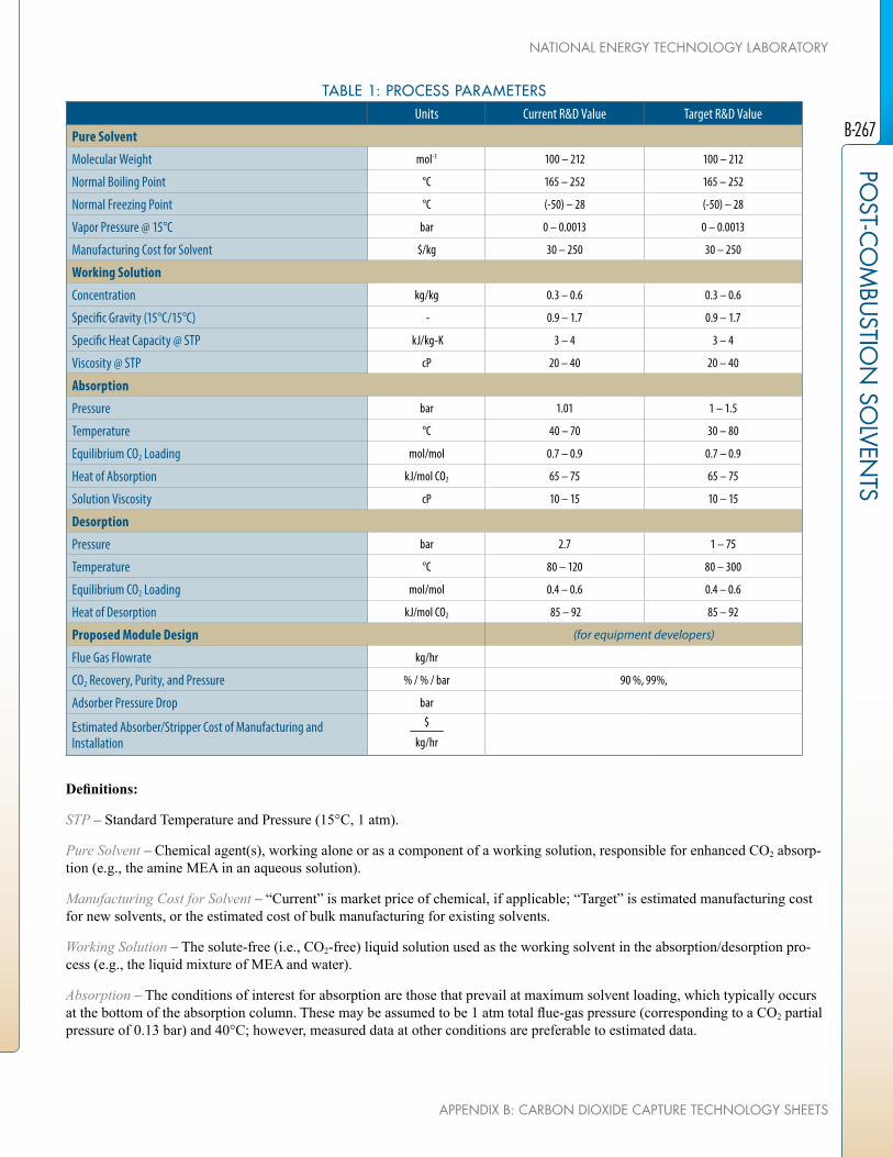
TABLE 1: PROCESS PARAMETERSUnits Current R&D Value Target R&D Value
Pure Solvent
Molecular Weight mol-1 100 – 212 100 – 212
Normal Boiling Point °C 165 – 252 165 – 252
Normal Freezing Point °C (-50) – 28 (-50) – 28
Vapor Pressure @ 15°C bar 0 – 0.0013 0 – 0.0013
Manufacturing Cost for Solvent $/kg 30 – 250 30 – 250
Working Solution
Concentration kg/kg 0.3 – 0.6 0.3 – 0.6
Specific Gravity (15°C/15°C) - 0.9 – 1.7 0.9 – 1.7
Specific Heat Capacity @ STP kJ/kg-K 3 – 4 3 – 4
Viscosity @ STP cP 20 – 40 20 – 40
Absorption
Pressure bar 1.01 1 – 1.5
Temperature °C 40 – 70 30 – 80
Equilibrium CO2 Loading mol/mol 0.7 – 0.9 0.7 – 0.9
Heat of Absorption kJ/mol CO2 65 – 75 65 – 75
Solution Viscosity cP 10 – 15 10 – 15
Desorption
Pressure bar 2.7 1 – 75
Temperature °C 80 – 120 80 – 300
Equilibrium CO2 Loading mol/mol 0.4 – 0.6 0.4 – 0.6
Heat of Desorption kJ/mol CO2 85 – 92 85 – 92
Proposed Module Design (for equipment developers)
Flue Gas Flowrate kg/hr
CO2 Recovery, Purity, and Pressure % / % / bar 90 %, 99%,
Adsorber Pressure Drop bar
Estimated Absorber/Stripper Cost of Manufacturing and Installation
$
kg/hr
Definitions:
STP – Standard Temperature and Pressure (15°C, 1 atm).
Pure Solvent – Chemical agent(s), working alone or as a component of a working solution, responsible for enhanced CO2 absorp-tion (e.g., the amine MEA in an aqueous solution).
Manufacturing Cost for Solvent – “Current” is market price of chemical, if applicable; “Target” is estimated manufacturing cost for new solvents, or the estimated cost of bulk manufacturing for existing solvents.
Working Solution – The solute-free (i.e., CO2-free) liquid solution used as the working solvent in the absorption/desorption pro-cess (e.g., the liquid mixture of MEA and water).
Absorption – The conditions of interest for absorption are those that prevail at maximum solvent loading, which typically occurs at the bottom of the absorption column. These may be assumed to be 1 atm total flue-gas pressure (corresponding to a CO2 partial pressure of 0.13 bar) and 40°C; however, measured data at other conditions are preferable to estimated data.
B-267
POST-C
OM
BUSTIO
N SO
LVENTS
APPENDIX B: CARBON DIOXIDE CAPTURE TECHNOLOGY SHEETS
NATIONAL ENERGY TECHNOLOGY LABORATORY
Desorption – The conditions of interest for desorption are those that prevail at minimum solvent loading, which typically occurs at the bottom of the desorption column. Operating pressure and temperature for the desorber/stripper are process-dependent (e.g., an MEA-based absorption system has a typical CO2 partial pressure of 1.8 bar and a reboiler temperature of 120°C). Measured data at other conditions are preferable to estimated data.
Pressure – The pressure of CO2 in equilibrium with the solution. If the vapor phase is pure CO2, this is the total pressure; if it is a mixture of gases, this is the partial pressure of CO2. Note that for a typical pulverized coal (PC) power plant, the total pressure of the flue gas is about 1 atm and the concentration of CO2 is about 13.2 percent. Therefore, the partial pressure of CO2 is roughly 0.132 atm or 0.130 bar.
Concentration – Mass fraction of pure solvent in working solution.
Loading – The basis for CO2 loadings is moles of pure solvent.
Estimated Cost – Basis is kg/hr of CO2 in CO2-rich product gas; assuming targets are met.
Other Parameter Descriptions:
Chemical/Physical Solvent Mechanism –
Absorber: Amine + CO2 ↔ Amine-CO2
Recirculation tank: Amine-CO2 + K2CO3 + H2O ↔ Amine + 2 KHCO3↓
Regenerator: 2 KHCO3 + (NH4+) → K2CO3 + H2O + CO2↑ + (NH4+)
Solvent Contaminant Resistance – Sulfur dioxide (SO2) has little impact to amine as amine is regenerated by chemical rather than thermal methods. It is expected that the amine employed should be much more resistance to oxygen (O2) and nitrogen oxides (NOx) than MEA. Nevertheless, the reaction kinetics and products of O2 and NOx with amine need to be investigated.
Solvent Foaming Tendency – Solvent foaming was not observed in laboratory experiments.
Flue Gas Pretreatment Requirements – Flue gas from coal-fired power plants equipped with conventional pollution control sys-tems does not require additional pretreatment. Residual SO2 after dissolution can be separated from the liquid stream as K2SO3/K2SO4 precipitates. The formation of heat-stable salts with amine should not be an issue, as amine is regenerated by chemical rather than thermal methods involving steam.
Solvent Make-Up Requirements – Amine is confined in the low-temperature absorber and recirculation tank loop. As a result, the thermal degradation, chemical degradation (due to the reactions with flue gas trace constituents), and emission loss (due to the volatility) are expected to be insignificant compared to the benchmark MEA process. A long-term integration test that lasts a sig-nificant number of hours will be needed to determine the amine’s make-up requirements. KHCO3 and K2CO3 are stable chemicals and do not degrade under high temperature operation in the regenerator.
Waste Streams Generated – Waste streams from the absorber/recirculation tank low-temperature loop may contain trace amount of fly ash, dissolved NOx, and amine degradation products. Waste streams from the stripper are expected to contain K2SO3 and K2SO4, if SO2 polishing is not equipped ahead of the CO2 capture system.
Process Design Concept –
B-268
POST
-CO
MBU
STIO
N S
OLV
ENTS
U.S. DEPARTMENT Of ENERGY
ADVANCED CARBON DIOXIDE CAPTURE R&D PROGRAM: TECHNOLOGY UPDATE, MAY 2013

figure 1: Process Design Concept
Proposed Module Design – Unless noted, flue gas feed pressure is 1.014 bara, temperature is 57°C, and composition leaving the flue gas desulfurization (FGD) unit (wet basis) should be assumed:
Composition (% vol) Composition (ppmv)CO2 H2O N2 O2 Ar SOx NOx
13.17 17.25 66.44 2.34 0.8 42 74
technology advantages
• Possession of high-CO2 absorption kinetics, resulting in an acceptable absorber capital cost.
• Reduction of processing water, resulting in reduced solvent regeneration energy demands.
• Employment of low-heat capacity KHCO3/K2CO3, resulting in reduced sensible heat demands.
• Reduction of reagent loss and equipment corrosion, resulting in reduced operation costs.
• Reduction of emission as KHCO3 can be treated at high temperature without any emissions of heat degradable harmful prod-ucts.
R&D challenges
• Handling of slurry/solid.
• Design of a regenerator for decomposing KHCO3 slurry with pressurized steam.
• Optimization of a transformative solvent system involving chemical regeneration of amine requires a significant effort.
results to date/accomplishments
• Evaluated more than 50 amines and amino acid salts for CO2 absorption amenable for the new solvent regeneration approach.
• Compared relative CO2 absorption efficiencies of various lean amines regenerated by chemical methods.
• Investigated conditions required for phase separation and determined phase diagrams following chemical regeneration of lean amine in the recirculation tank in attempt to understand its chemical and physical behaviors.
• Elucidated the kinetics and mechanisms of CO2 absorption and chemical regeneration involved in the new solvent system.
B-269
POST-C
OM
BUSTIO
N SO
LVENTS
APPENDIX B: CARBON DIOXIDE CAPTURE TECHNOLOGY SHEETS
NATIONAL ENERGY TECHNOLOGY LABORATORY

• Constructed a stripper system equipped with a calorimeter for the determination of K2CO3 regeneration rates and energy de-mands. Preliminary result indicated that K2CO3 regeneration energy demand was 2,079 kJ/kg CO2 at steady state conditions, which is approximately 40 percent less than that of MEA.
• Performed a semi-continuous integration test encompassing CO2 absorption in the absorber, amine regeneration in the recir-culation tank, and K2CO3 regeneration and CO2 production in the stripper.
• Performed mass and water balances, and developed a stream table of the bench-scale new solvent system.
next steps
Project completed May 31, 2013.
available reports/technical papers/presentations
Chang, S-g, “Developing Chemical Additives for Aqueous Ammonia to Reduce CO2 Capture Cost,” presented at the Annual NETL CO2 Capture Technology for Existing Plants Meeting, Pittsburgh, Pennsylvania, March 2009. http://www.netl.doe.gov/pub-lications/proceedings/09/CO2/pdfs/11231%20LBNL%20solvents%20%28Chang%29%20mar09.pdf.
Chang, S-g, “Development of Chemical Additives for CO2 Capture Cost Reduction,” presented at the 2010 NETL CO2 Capture Technology Meeting, Pittsburgh, Pennsylvania, September 2010. http://www.netl.doe.gov/publications/proceedings/10/co2cap-ture/presentations/monday/Ted%20Chang-LBNL.pdf.
Chang, S-g, “Development of Chemical Additives for CO2 Capture Cost Reduction,” presented at the 2011 NETL CO2 Capture Technology Meeting, Pittsburgh, Pennsylvania, August 2011. http://www.netl.doe.gov/publications/proceedings/11/co2capture/presentations/2-Tuesday/23Aug11-Chang-LBNL-Additives%20for%20Reducing%20CO2%20Capture%20Costs.pdf.
Chang, S-g, “Development of Chemical Additives for CO2 Capture Cost Reduction,” presented at the 2012 NETL CO2 Capture Technology Meeting, Pittsburgh, Pennsylvania, August 2012. http://www.netl.doe.gov/publications/proceedings/12/co2capture/presentations/2-Tuesday/T%20Chang-LBNL-Additives.pdf.
B-270
POST
-CO
MBU
STIO
N S
OLV
ENTS
U.S. DEPARTMENT Of ENERGY
ADVANCED CARBON DIOXIDE CAPTURE R&D PROGRAM: TECHNOLOGY UPDATE, MAY 2013

DEVELOPMENT Of AN ENERGY-EffICIENT, ENVIRONMENTALLY fRIENDLY SOLVENT fOR THE CAPTURE Of CO2
primary project goals
This Babcock & Wilcox Power Generation Group, Inc., (B&W) project identifies concen-trated piperazine (PZ)-based solvent formulations that improve overall solvent and system performance.
technical goals
• Improve system operability and reliability.
• Minimize environmental impacts.
• Reduce corrosion potential.
• Maximize solvent durability.
technical content
B&W is characterizing and optimizing the formulation of a novel solvent for the capture of carbon dioxide (CO2) at coal-fired utility plants. The work will be performed on a solvent that has been identified through a five-year solvent development program conducted at B&W. The solvent formulations of interest comprise concentrated solutions of a cyclic diamine, PZ. Recent testing at B&W indicates that blends of concentrated PZ with other compounds have the potential to perform substantially better than PZ itself. The objective of the proposed work is to lower the total cost of solvent-based CO2 capture systems by identifying formulations that will improve overall solvent and system performance.
technology maturity:
Bench-Scale, Simulated and Actual flue Gas
project focus:
Optimized Solvent formulation
participant:
Babcock & Wilcox
project number:
fE0007716
NETL project manager:
Bruce [email protected]
principal investigator:
George farthingBabcock & [email protected]
partners:
University of Cincinnatifirst Energy
performance period:
10/1/11 – 4/30/13
figure 1: B&W 7-Ton/Day Pilot facility
B-271
POST-C
OM
BUSTIO
N SO
LVENTS
APPENDIX B: CARBON DIOXIDE CAPTURE TECHNOLOGY SHEETS
NATIONAL ENERGY TECHNOLOGY LABORATORY

Other Parameter Descriptions:
Chemical/Physical Solvent Mechanism – The CO2-reactive species (there may be other non-reactive species) in the solvent for-mulation may include amines, carbonates, or amino acid salts in combination with concentrated PZ. Amine solvents are grouped according to their molecular structure. Carbonate and amine reactions with CO2 can be summarized as follows:
Carbonates: CO3= + CO2 +H2O ↔ 2 HCO3-
Hindered and tertiary amines: CO2 + R3N+ H2O ↔ HCO3- + R3NH+
Primary and secondary amines: CO2 + 2R2NH ↔ R2NCOO- + R2NH2+
Solvent Contaminant Resistance – Amine solvents chemically degrade in a variety of ways (thermal degradation due to exposure to the high temperatures of the regeneration process, oxidative degradation due the presence of oxygen in the flue gas, carbamate polymerization, etc). Degradation reactions can be accelerated by the presence of degradation or corrosion products and heat-stable salts, and through the catalytic effects of various metals (possibly originating with the coal fly ash). It is a central objective of this project to minimize solvent degradation and the attendant production of potentially hazardous chemical species.
Flue Gas Pretreatment Requirements – Flue gas supplied to the CO2 capture system will need to be cooled to approximately 40°C and be relatively free of contaminants. Concentrations of sulfur dioxide (SO2) and nitrogen dioxide (NO2) will need to be less than about 10 parts per million (ppm) – preferably around 1 ppm.
Solvent Make-Up Requirements – Solvent makeup is required to offset solvent losses due to volatility, degradation, the formation of heat stable salts, etc. PZ-based solvents are expected to minimize such losses due to the lower volatility and better resistance to thermal degradation exhibited by PZ relative to solvents such as monoethanolamine (MEA). Work during the project is specifi-cally aimed at reducing such losses.
Waste Streams Generated – Waste streams generated by the process will be similar to those generated by convention amine pro-cesses, including reclaimer waste solids; spent carbon and particulate filter cake from solvent filtration equipment; and, potential-ly, waste water. It is the objective of this project to minimize the environmental impact of these streams through careful selection of the solvent formulation and operating conditions.
Process Design Concept – The CO2 capture process, illustrated in Figure 2, comprises a relatively conventional absorption/strip-ping process.
figure 2: Schematic of Solvent-Based CO2 Capture Process
B-272
POST
-CO
MBU
STIO
N S
OLV
ENTS
U.S. DEPARTMENT Of ENERGY
ADVANCED CARBON DIOXIDE CAPTURE R&D PROGRAM: TECHNOLOGY UPDATE, MAY 2013

technology advantages
Piperazine, used alone, has demonstrated high rates of absorption and low regeneration energy. Recent testing at B&W indicates that blends of concentrated PZ with other organic compounds may perform substantially better than PZ alone.
R&D challenges
• Selection of a solvent formulation involves compromises which seek to optimally balance competing effects. Using limited and potentially non-representative data generated in laboratory-scale equipment is extremely challenging. B&W will use previous solvent development work to correlate laboratory results with pilot-scale performance.
• Some of the improvement goals include improved system operability and reliability, minimizing environmental impacts, reducing corrosion potential, and maximizing solvent durability.
results to date/accomplishments
• A list of candidate solvent formulations was developed and refined. This work comprised evaluations regarding overall solvent performance criteria, identification of primary active components, and verification of wet chemistry analytical tech-niques for CO2 loading and alkalinity.
• Several modeling approaches were identified. Tools considered include equilibrium models, semi-empirical rate-based mod-els, and rigorous rate-based models. Tools for the prediction of process economics were also evaluated.
• Characterization tests in B&W’s Wetted-Wall Column (WWC) were completed on a baseline concentrated PZ solvent and 12 candidate solvent formulations. The liquid film mass transfer coefficient (kg), as well as equilibrium partial pressure of CO2 (PCO2*), were obtained from each WWC test. Other parameters, such as heat of absorption and CO2 working capacity, were also derived from these experimental data. Preliminary solvent formulation performance was then estimated with in-house, semi-empirical models.
• Solvent volatility and solubility testing was performed on several candidate formulations of concentrated PZ solutions con-taining salts of amino acids, carbonates, and other amines. Also evaluated were organic additives designed to improve the solubility of PZ and its carbamates. In addition, it was found necessary to characterize candidate formulations with respect to their viscosities in order to ensure good mass transfer performance and acceptable operability.
• Installation of the bench-scale Continuous Solvent Degradation System (CSDS) was completed. The CSDS will enable comprehensive investigations of proposed solvent formulation degradation under representative operating conditions. It is intended to simulate key features of industrial CO2 capture processes, including cyclical absorption and regeneration process conditions. The CSDS is designed for continuous, unattended operation for tests lasting 100 to 1,000 hours or more.
next steps
• Identify several candidate formulations of a concentrated PZ-based solvent for detailed characterization and evaluation.
• Complete Budget Period 1 reporting requirements.
• Close out contract. B&W has elected to terminate the cooperative agreement effective April 30, 2013.
available reports/technical papers/presentations
Farthing, G., “Optimized Solvent for Energy-Efficient, Environmentally Friendly Capture of CO2 at Coal-Fired Power Plants,” presented at the 2012 NETL CO2 Capture Technology Meeting, Pittsburgh, Pennsylvania, July 2012. http://www.netl.doe.gov/pub-lications/proceedings/12/co2capture/presentations/2-Tuesday/G%20Farthing-B%26W-Optimized%20Solvent.pdf.
B-273
POST-C
OM
BUSTIO
N SO
LVENTS
APPENDIX B: CARBON DIOXIDE CAPTURE TECHNOLOGY SHEETS
NATIONAL ENERGY TECHNOLOGY LABORATORY

POST-COMBUSTION CO2 CAPTURE fOR EXISTING PC BOILERS BY SELf-CONCENTRATING AMINE ABSORBENT
primary project goals
3H Company set out to experimentally and analytically confirm the feasibility of the proposed Self-Concentrating Absorbent CO2 Capture Process, with the goal of developing a sound engineering design, supported by laboratory data and economic justification, for a flue gas slipstream-testing unit.
technical goals
• Perform laboratory screening experiments to identify different absorbent/solvent combinations that can exhibit the “self-concentrating” carbon dioxide (CO2) absorption effect, and conduct fundamental absorption/regeneration rates and physical and chemi-cal property measurements to allow its process design and techno-economic feasibility to be evaluated.
• Conduct experiments to demonstrate the process under dynamic column testing condi-tions and to develop a process design package for a slipstream testing facility.
technical content
This project examined an innovative and proprietary CO2 capture technology developed by 3H Company. The process is based on amine and/or other chemical absorbents in a non-aqueous solvent that can phase separate into a distinct CO2-rich liquid phase upon reac-tion with CO2. The process was demonstrated using commercially available amines and solvents. The technology has the potential of not only greatly reducing the energy penalty associated with regeneration compared to conventional monoethanolamine (MEA)-based processes, but it can also increase the amine CO2 absorption rate. Preliminary experimental data shows that the proposed Self-Concentrating Amine Absorbent process has the potential of reducing the total regeneration energy by as much as 70 percent.
The technology removes CO2 from power plant flue gas, using an absorbent (e.g., amine or special designed chemical species) and a matched solvent, which rapidly forms two immis-cible liquid phases upon absorbing CO2 (Figure 1). The process has been demonstrated in the laboratory for a number of specific amine/solvent pairs. The solvents employed are non-aqueous. The novelty of the concept rests on the duel hydrophobic/hydrophilic functionality of the CO2 absorbents (e.g., amine), the stability of the “CO2-rich” reaction product, and its solubility behavior within the non-aqueous solvent system employed. When an amine is used as the CO2 absorbent, it is reasonable to assume that the chemistry follows that for an aqueous-based system. However, in the presence of a Self-Concentrating Solvent, the CO2:amine reaction forms a stable product that can be solvated in higher concentration within the solvent system. The chemistry and mechanism of the process requires additional research and development (R&D).
technology maturity:
Laboratory-Scale, Simulated flue Gas
project focus:
CO2 Capture with Self-Concentrating Amine Absorbent
participant:
3H Company
project number:
fE0004274
NETL project manager:
Morgan [email protected]
principal investigator:
Liang Hu3H [email protected]
partners:
Nexant, Inc.LG&E and KU Energy LLCEPRI
performance period:
10/1/10 – 1/31/13
B-274
POST
-CO
MBU
STIO
N S
OLV
ENTS
U.S. DEPARTMENT Of ENERGY
ADVANCED CARBON DIOXIDE CAPTURE R&D PROGRAM: TECHNOLOGY UPDATE, MAY 2013

figure 1: Concept of the Proposed Self-Concentrating Amine Absorbent Process
Conventional 30 wt% MEA-based CO2 capture is considered to be the benchmark for performance. A typical heat of regeneration for a 30 percent MEA CO2 capture process is about 1,934 Btu/lb CO2, as cited in the literature, and only about 1/3 of the regenera-tion energy is used to break the amine:CO2 bonds. Minimizing the overall heat of regeneration by using a unique absorbent/solvent system is the key to the Self-Concentrating Absorbent process. Figure 2 shows a flow scheme for the concept, using amine as the CO2 absorbent. The flow scheme is similar to a conventional MEA process, with the exception that a decanter is incorpo-rated downstream of the absorber to allow the “rich CO2 liquid” to be fully phase separated before sending it onto the stripper. Only the “rich CO2 liquid” is subjected to regeneration, at a significant reduced volume as compared to a conventional MEA process. Overall, a 70 percent reduction in heat of regeneration can be achieved with the Self-Concentrating Absorbent process, taking into consideration that (1) only the “rich CO2/solvent liquid” will be sent onto regeneration with minimum excess solvent, and (2) the solvent has a lower heat capacity and heat of vaporization than water. Because the process uses a non-aqueous system, many of the problems associated with MEA, including degradation due to corrosion, oxygen degradation, and the formation of stable salts, are expected to be mitigated. These types of effects, along with the potential environmental emissions and health problems associated with the use of the non-aqueous process, will need to be investigated in more detail.
figure 2: Simplified flow Scheme of the Proposal Self-Concentrating Amine Absorbent Concept
B-275
POST-C
OM
BUSTIO
N SO
LVENTS
APPENDIX B: CARBON DIOXIDE CAPTURE TECHNOLOGY SHEETS
NATIONAL ENERGY TECHNOLOGY LABORATORY

technology advantages
• Lower regeneration energy requirements.
• Minimal degradation due to corrosion, oxygen degradation, and the formation of stable salts.
R&D challenges
• The chemistry, kinetics, and mass-transfer characteristics governing the diffusion of CO2 into the liquid phase where it reacts with amine within the non-aqueous solvent, etc., are unknown.
• The self-concentrating process involves the phase separation of the “CO2 rich” reaction product from the solvent system, of which its stability, composition, phase behavior, thermodynamic miscibility, and solubility limit are unknown.
• It is necessary to develop some basic theoretical and mechanistic understanding of the process so that R&D will not have to be based purely on an empirical approach.
results to date/accomplishments
• Completed preliminary system analysis and process design study comparing the 3H process to 30 percent MEA.
• Completed bench-scale screening, property measurement, and testing to identify all four promising Self-Concentrating Ab-sorbent/Solvent pairs for more detailed characterization and evaluation.
• Completed down-selection to two promising Self-Concentrating Absorbent/Solvent pairs and commenced detailed characteri-zation and analysis of these two final absorbent/solvent pairs.
next steps
This project ended on January 31, 2013.
available reports/technical papers/presentations
Hu, L., “Post-Combustion CO2 Capture for Existing PC Boilers by Self-Concentrating Absorbent,” presented at the 2012 NETL CO2 Capture Technology Meeting, Pittsburgh, Pennsylvania, July 2012. http://www.netl.doe.gov/publications/proceedings/12/co-2capture/presentations/2-Tuesday/L%20Hu-%203H%20Company-Self-concentrating%20Absorbent.pdf.
B-276
POST
-CO
MBU
STIO
N S
OLV
ENTS
U.S. DEPARTMENT Of ENERGY
ADVANCED CARBON DIOXIDE CAPTURE R&D PROGRAM: TECHNOLOGY UPDATE, MAY 2013

IONIC LIQUIDS: BREAKTHROUGH ABSORPTION TECHNOLOGY fOR POST-COMBUSTION CO2 CAPTURE
primary project goals
The University of Notre Dame set out to develop a new ionic liquid (IL) solvent capture process resulting in a small increase in cost of electricity (COE) compared to currently available capture technologies by overcoming viscosity and capacity issues impacting cost and performance of ILs via “proof-of-concept” exploration and laboratory-/bench-scale testing of a variety of IL formulations.
technical goals
• Design and synthesize one or more IL absorbents tailored for post-combustion carbon dioxide (CO2) capture.
• Perform atomistic-level classical and quantum calculations to engineer IL structures maximizing CO2 carrying capacity with minimal regeneration costs.
• Measure or accurately estimate all physical solvent properties essential for detailed engineering and design calculations:
- Gas solubility, viscosity, heat of absorption, heat capacity, mass transfer coeffi-cients, thermal decomposition, chemical stability, and corrosivity.
• Complete detailed systems and economic analysis.
• Demonstrate CO2 capture technology on a continuous lab-scale unit.
technical content
ILs are salts that are liquid at room temperature. They are known to have high intrinsic physical solubility for CO2. Examples of ILs are illustrated in Figure 1.
technology maturity:
Laboratory-Scale, Simulated flue Gas
project focus:
Ionic Liquids
participant:
University of Notre Dame
project number:
fC26-07NT43091
NETL project manager:
David [email protected]
principal investigator:
Edward J. MaginnUniversity of Notre [email protected]
partners:
Babcock and WilcoxDTETrimeric CorporationKoei Chemical
performance period:
2/28/07 – 9/30/12
B-277
POST-C
OM
BUSTIO
N SO
LVENTS
APPENDIX B: CARBON DIOXIDE CAPTURE TECHNOLOGY SHEETS
NATIONAL ENERGY TECHNOLOGY LABORATORY

figure 1: Examples of Ionic Liquids figure 2: Isotherms confirming 1:1 binding
A close-to-conventional absorber/stripper process is assumed for process modeling and costing. Process simulation has been used to evaluate the sensitivity of a representative 500-MW (gross capacity), coal-fired power plant CO2 capture process for the proper-ties of ILs. The results were used to guide the development of the next generation of ILs. Salient project details include:
• Anion/cation functionalization: Notre Dame has developed both 1:1 and 2:1 (IL:CO2) stoichiometries by adding chemical functionality to the anion and cation, respectively. Molecular modeling calculations were used to identify anion-functional-ized ILs with minimal increase in solvent viscosity after CO2 absorption. Two ILs (NDIL0046 and NDIL0157) were identi-fied. NDIL0046 was used for lab-scale experimental tests, and data on NDIL0157 was used for techno-economic analysis.
• Enthalpy of reaction: Process modeling indicated that the binding strength of NDIL0046 needed to be improved, and a new IL (NDIL0157) with optimal enthalpy of reaction and lower heat capacity was identified. Optimal reaction enthalpy leads to higher CO2 solvent capacities, reduced solvent circulation rate, and lowered sensible heating load.
Results show much lower parasitic energy compared with a monoethanolamine (MEA) system. From techno-economic analysis, it was estimated that the parasitic electricity losses in the reboiler are reduced by 36 percent, compression load increased by 14 percent, and the auxiliary losses in CO2 capture are lowered by 34 percent. The best-case IL (NDIL0157) has almost the same increase in levelized cost of electricity (LCOE) compared with MEA due to higher capital costs for the CO2 capture system.
figure 3: Results from Sensitivity Studies on the Parasitic Power Requirement of Ionic Liquid Solvents
B-278
POST
-CO
MBU
STIO
N S
OLV
ENTS
U.S. DEPARTMENT Of ENERGY
ADVANCED CARBON DIOXIDE CAPTURE R&D PROGRAM: TECHNOLOGY UPDATE, MAY 2013

TABLE 1: PROCESS PARAMETERS FOR IONIC LIQUID SOLVENTSUnits Current R&D Value Target R&D Value
Pure Solvent
Molecular Weight mol-1 575 322
Normal Boiling Point °C N/A - does not boil N/A - does not boil
Normal Freezing Point °C < -10oC < -10oC
Vapor Pressure @ 15°C bar Essentially zero Essentially zero
Manufacturing Cost for Solvent $/kg $20/kg < $15/kg
Working Solution
Concentration kg/kg 0.998 > 0.9
Specific Gravity (15°C/15°C) - 0.907 ≈1.0
Specific Heat Capacity @ STP kJ/kg-K 2.25 <2.3
Viscosity @ STP cP 158 @40 c < 100
Absorption
Pressure bar 1.03 1
Temperature °C 40-52 40-52
Equilibrium CO2 Loading mol/mol 0.167 0.988
Heat of Absorption kJ/mol CO2 43 54
Solution Viscosity cP 129 < 100
Desorption
Pressure bar 1.3 1-3
Temperature °C 120-188 120-204
Equilibrium CO2 Loading mol/mol 0.041 0.51
Heat of Desorption kJ/mol CO2 43 54
Proposed Module Design (for equipment developers)
Flue Gas Flowrate kg/hr N/A
CO2 Recovery, Purity, and Pressure % / % / bar N/A
Adsorber Pressure Drop bar N/A
Estimated Absorber/Stripper Cost of Manufacturing and Installation
$
kg/hr N/A
Definitions:
STP – Standard Temperature and Pressure (15°C, 1 atm).
Pure Solvent – Chemical agent(s), working alone or as a component of a working solution, responsible for enhanced CO2 absorp-tion (e.g., the amine MEA in an aqueous solution).
Manufacturing Cost for Solvent – “Current” is market price of chemical, if applicable; “Target” is estimated manufacturing cost for new solvents, or the estimated cost of bulk manufacturing for existing solvents.
Working Solution – The solute-free (i.e., CO2-free) liquid solution used as the working solvent in the absorption/desorption pro-cess (e.g., the liquid mixture of MEA and water).
Absorption – The conditions of interest for absorption are those that prevail at maximum solvent loading, which typically occurs at the bottom of the absorption column. These may be assumed to be 1 atm total flue-gas pressure (corresponding to a CO2 partial pressure of 0.13 bar) and 40°C; however, measured data at other conditions are preferable to estimated data.
B-279
POST-C
OM
BUSTIO
N SO
LVENTS
APPENDIX B: CARBON DIOXIDE CAPTURE TECHNOLOGY SHEETS
NATIONAL ENERGY TECHNOLOGY LABORATORY

Desorption – The conditions of interest for desorption are those that prevail at minimum solvent loading, which typically occurs at the bottom of the desorption column. Operating pressure and temperature for the desorber/stripper are process-dependent (e.g., an MEA-based absorption system has a typical CO2 partial pressure of 1.8 bar and a reboiler temperature of 120°C). Measured data at other conditions are preferable to estimated data.
Pressure – The pressure of CO2 in equilibrium with the solution. If the vapor phase is pure CO2, this is the total pressure; if it is a mixture of gases, this is the partial pressure of CO2. Note that for a typical pulverized-coal power plant, the total pressure of the flue gas is about 1 atm and the concentration of CO2 is about 13.2 percent. Therefore, the partial pressure of CO2 is roughly 0.132 atm or 0.130 bar.
Concentration – Mass fraction of pure solvent in working solution.
Loading – The basis for CO2 loadings is moles of pure solvent.
Estimated Cost – Basis is kg/hr of CO2 in CO2-rich product gas; assuming targets are met.
Other Parameter Descriptions:
Chemical/Physical Solvent Mechanism – A 1:1 reaction with CO2 and the basic group on the anion of the IL.
Solvent Contaminant Resistance – Resistant to air; have not evaluated resistance to other contaminants.
Solvent Foaming Tendency – Low.
Flue Gas Pretreatment Requirements – Flue gas desulfurization (FGD) plus polishing column to get to 10 parts per million (ppm) sulfur oxide (SOx).
Solvent Make-Up Requirements – 3.15 tons/day for a 550-MW net plant.
Waste Streams Generated – Degraded solvent waste; negligible vapor emissions.
Process Design Concept – Flowsheet/block flow diagram, if not included above.
figure 4: Schematic of Process Design Concept
B-280
POST
-CO
MBU
STIO
N S
OLV
ENTS
U.S. DEPARTMENT Of ENERGY
ADVANCED CARBON DIOXIDE CAPTURE R&D PROGRAM: TECHNOLOGY UPDATE, MAY 2013

Proposed Module Design – Unless noted, flue gas feed pressure is 1.014 bara, temperature is 57°C, and composition leaving the flue gas desulfurization (FGD) unit (wet basis) should be assumed:
Composition (% vol) Composition (ppmv)CO2 H2O N2 O2 Ar SOx NOx
13.17 17.25 66.44 2.34 0.8 42 74
technology advantages
• Low volatility and good thermal stability.
• Wide liquidus range.
• Net-CO2 uptake by solvent can be varied by tuning the enthalpy of CO2 absorption (10 to 80 kJ/mol) through a combination of computational methods and experimental synthesis.
• Anhydrous absorption process.
• The viscosity of the current generation of ILs (NDIL0046) does not change significantly with CO2 absorption.
R&D challenges
• The solvent CO2 capacity (on a weight basis) should be higher than that for the best-case scenario (NDIL0157) to lower-solvent recirculation rates and reduce absorber costs.
• The effects of water on the corrosion behavior and CO2 reactivity of the ILs need to be examined in greater detail, though preliminary results show negligible corrosion for NDIL0046 + carbon steel.
• The chemically functionalized IL solvent mass-transfer characteristics/viscosity need to be improved to lower capital and operating costs.
• Low-cost commercial synthesis routes for Generation III ILs are required to lower operating costs.
results to date/accomplishments
All project phases (I, II, and III) are complete. Key accomplishments to date include:
• Discovered and synthesized a new class of non-aqueous ILs reacting with 1:1 stoichiometry, and with no increase in viscosity following CO2 absorption.
• Developed molecular modeling techniques that enabled the computation of key properties of ILs from first principles, and tuned the binding strength of ILs to optimize process economics.
• Demonstrated that the NDIL0046 IL had significantly lower corrosion rates compared to aqueous MEA, indicating that lower-cost materials could be used for absorber and heat exchangers.
• Techno-economic analysis on the best IL to date (NDIL0157) suggests favorable COE and significantly lower parasitic en-ergy losses compared to aqueous MEA (U.S. Department of Energy [DOE]/National Energy Technology Laboratory [NETL] Baseline Case 12).
• Developed unique experimental techniques, including the ability to monitor the infrared spectrum of the IL as it absorbs CO2, and then use this information to determine reaction rates and mechanisms.
B-281
POST-C
OM
BUSTIO
N SO
LVENTS
APPENDIX B: CARBON DIOXIDE CAPTURE TECHNOLOGY SHEETS
NATIONAL ENERGY TECHNOLOGY LABORATORY

next steps
The project ended on September 30, 2012. Recommendations for further steps include:
• Scale-up of experiments to the next level using synthetic flue gas and slipstream tests.
• The operating performance of ILs (mass-transfer characteristics, viscosity) would be improved.
• Process chemistry improvements needed to make ILs at tonne-scales for lower cost would be investigated.
• IL toxicity and long-term stability would also be examined.
available reports/technical papers/presentations
M. McCready et al., “Ionic Liquids: Breakthrough Absorption Technology for Post-Combustion CO2 Capture,” presented at the 2012 NETL CO2 Capture Technology Meeting, Pittsburgh, Pennsylvania, July, 2012. Available at: http://www.netl.doe.gov/publi-cations/proceedings/12/co2capture/presentations/2-Tuesday/M%20McCready-Notre%20Dame-Ionic%20Liquids.pdf.
W. F. Schneider and E. Mindrup, “First-Principles Evaluation of CO2 Complexation In Functionalized Ionic Liquids,” Symposium on Ionic Liquids: From Knowledge to Application, American Chemical Society National Meeting, Philadelphia, Pennsylvania, August 17-21, 2008.
K. E. Gutowski and E. J. Maginn, “Amine-Functionalized Task Specific Ionic Liquids for CO2 Capture,” Symposium on Ionic Liquids: From Knowledge to Application, American Chemical Society National Meeting, Philadelphia, Pennsylvania, August 17-21, 2008.
Joan F. Brennecke, “CO2 Capture – Challenges and Opportunities,” Energy, Citizens and Economic Transformation for Indiana and America, University of Notre Dame, July 7, 2008.
Joan F. Brennecke, Jessica L. Anderson, Alexandre Chapeaux, Devan E. Kestel, Zulema K. Lopez-Castillo, and Juan C. de la Fuente, “Carbon Dioxide Capture Using Ionic Liquids,” 236th ACS National Meeting, Philadelphia, Pennsylvania, August 17, 2008.
E. M. Mindrup and W. F. Schneider, “Comparison of Functionalized Amine Energetics for CO2 Capture,” poster presented at the AIChE Annual Meeting, Philadelphia, Pennsylvania 2008.
Wei Shi and E. J. Maginn, “Molecular simulation of pure and mixture gases absorption in ionic liquids,” presented at the AIChE Annual Meeting, Philadelphia, Pennsylvania 2008.
Wei Shi and E. J. Maginn, “Molecular simulation and regulation solution theory modeling of pure and mixed gas absorption in the ionic liquid 1-n-butyl-3- methylimidazolium Bis(Trifluoromethylsulfonyl)amide ([hmim][Tf2N]),” Journal of Physical Chemistry B, 112(51), 16710-16720.
Fisher, K.S., et al. Advanced Amine Solvent Formulations and Process Integration for Near-Term CO2 Capture Success. Final Report to DOE/NETL. Grant No. DE-FG02-06ER84625, June 2007.
Christina Myers, Henry Pennline, David Luebke, Jeffery Ilconich, JaNeille Dixon, Edward J. Maginn, and Joan F. Brennecke, “High Temperature Separation of Carbon Dioxide/Hydrogen Mixtures Using Facilitated Supported Liquid Membranes,” Journal of Membrane Science, 2008, 322, 28-31.
Xiaochun Zhang, Feng Huo, Zhiping Liu, Wenchuan Wang, Edward Maginn and Wei Shi, “Absorption of CO2 in the Ionic Liquid 1-n-hexyl-3-methylimidazolium tris(pentafluoroethyl)trifluorophosphate ([hmim][FEP]): A Molecular View by Computer Simula-tions,” Journal of Physical Chemistry B, 2009, 113, 7591-7598.
Keith Gutowski and Edward J. Maginn, “Amine-Functionalized Task-Specific Ionic Liquids: A Mechanistic Explanation for the Dramatic Increase in Viscosity Upon Complexation with CO2 from Molecular Simulation,” Journal of the American Chemical Society, 2008, 130, 14690-14704.
B-282
POST
-CO
MBU
STIO
N S
OLV
ENTS
U.S. DEPARTMENT Of ENERGY
ADVANCED CARBON DIOXIDE CAPTURE R&D PROGRAM: TECHNOLOGY UPDATE, MAY 2013

E. J. Maginn, Developing New Ionic Liquids for CO2 Capture: A Success Story for Thermodynamics and Computational Mo-lecular Design, GE Global Research Symposium on Emissions and Aftertreatment, GE Global Research Center, Niskayuna, New York, Sept. 17, 2009.
Marcos Perez-Blanco and Edward J. Maginn, “Molecular Dynamics Simulations of CO2 at an Ionic Liquid Interface: Adsorption, Ordering and Interfacial Crossing,” Journal of Physical Chemistry B (cover article), 2010, 36, 11827.
W. F. Schneider, “Ionic Liquids for CO2 Capture from First-Principles,” CECAM workshop on Carbon Capture, Lausanne, Swit-zerland, July 26-28, 2010.
W. F. Schneider and E. Mindrup, “AHA! Computational design of aprotic heterocyclic anions for ionic-liquid-based CO2 separa-tions,” Division of Fuel Chemistry, American Chemical Society National Meeting, Boston, Massachusetts, August 22-26, 2010.
Burcu E. Gurkan, Juan C. de la Fuente, Elaine M. Mindrup, Lindsay E. Ficke, Brett F. Goodrich, Erica A. Price, William F. Sch-neider, and Joan F. Brennecke, “Equimolar CO2 absorption by anion-functionalized ionic liquids,” J. Am. Chem. Soc., 132, 2010, 2116-2117.
Burcu E. Gurkan, Juan de la Fuente, Elaine M. Mindrup, Lindsay E. Ficke, Brett F. Goodrich, Erica A. Price, William F. Sch-neider, Edward J. Maginn and Joan F. Brennecke, “Chemically Complexing Ionic Liquids for Post-Combustion CO2 Capture,” Clearwater Clean Coal Conference, Clearwater, FL, June 6-10, 2010.
Edward J. Maginn, “Molecular engineering of new ionic liquid sorbents for CO2 capture” at the 9th Annual Carbon Capture and Sequestration Meeting, Pittsburgh, Pennsylvania, May 2010.
Edward J. Maginn, Joan F. Brennecke, William F. Schneider, and Mark J. McCready, “Ionic Liquids: Breakthrough Absorption Technology for Post-combustion CO2 Capture,” presented at the NETL CO2 Capture Technology Meeting, Pittsburgh, Pennsylva-nia, September, 2010.
B-283
POST-C
OM
BUSTIO
N SO
LVENTS
APPENDIX B: CARBON DIOXIDE CAPTURE TECHNOLOGY SHEETS
NATIONAL ENERGY TECHNOLOGY LABORATORY

DEVELOPMENT AND EVALUATION Of A NOVEL INTEGRATED VACUUM CARBONATE ABSORPTION PROCESS
primary project goals
The Illinois State Geological Survey (ISGS) set out to prove the novel Integrated Vacuum Carbonate Absorption Process (IVCAP) concept and further improve the energy efficiency of the process for post-combustion carbon dioxide (CO2) capture.
technical goals
• Test the proof-of-concept of the IVCAP.
• Identify an effective catalyst for accelerating CO2 absorption.
• Identify an effective additive for reducing the stripping heat.
• Evaluate a modified IVCAP as a multi-pollutant control process for combined sulfur dioxide (SO2) and CO2 capture.
technical content
The proposed IVCAP employs a potassium carbonate (K2CO3) aqueous solution for CO2 absorption. While the absorption takes place at atmospheric pressure, the stripper is oper-ated under a vacuum condition. As seen in Figure 1 and Table 1, the low heat of reaction between CO2 and K2CO3 favors a stripping process operated at a low temperature and the low-quality steam (close to the exhaust end of low-pressure turbine in the power plant) can be used as a heat source for the stripping process as a result.
figure 1: Steam Properties During Expansion in the Intermediate- and Low-Pressure Turbines
technology maturity:
Laboratory-Scale, Simulated flue Gas
project focus:
Novel Integrated Vacuum Carbonate Process
participant:
Illinois State Geological Survey
project number:
NT0005498
NETL project manager:
Andrew [email protected]
principal investigator:
Yongqi LuIllinois State Geological [email protected]
partners:
Calgon Carbon CorporationIllinois Clean Coal InstituteUniversity of Illinois
performance period:
10/1/08 – 4/30/12
B-284
POST
-CO
MBU
STIO
N S
OLV
ENTS
U.S. DEPARTMENT Of ENERGY
ADVANCED CARBON DIOXIDE CAPTURE R&D PROGRAM: TECHNOLOGY UPDATE, MAY 2013

figure 2: Vacuum Stripping in the IVCAP Allows for Use of Low-Quality Steam from the Power Plant
TABLE 1: A COMPARISON OF HEATS OF ABSORPTION FOR CO2 SOLVENTS
Solvent Main Reaction Heat of AbsorptionPrimary/Secondary Amines 2RR’NH + CO2 = RR’NCOO- + RR’NH2+ MEA: 1,900 kJ/kg
Tertiary Amine RR’R’’N + CO2 + H2O = HCO3- + RR’R’’NH+ MDEA: 1,200 kJ/kg
Carbonate CO32- + CO2 +H2O = 2 HCO3- 600 kJ/kg
The intrinsic rate of CO2 absorption into the K2CO3 solution is much slower than that in a monoethanolamine (MEA) solution; therefore, enzyme catalysts were developed to promote the absorption rate. Unlike the mixing of another solvent into a primary solvent, a catalyst accelerates the absorption rate without increasing the heat of absorption of the solvent.
B-285
POST-C
OM
BUSTIO
N SO
LVENTS
APPENDIX B: CARBON DIOXIDE CAPTURE TECHNOLOGY SHEETS
NATIONAL ENERGY TECHNOLOGY LABORATORY

The enzyme catalysts will need to be immobilized in order to:• Reduce enzyme leakage in a flow system.• Improve chemical stability of enzymes.• Improve thermal stability of enzymes.
Three supportive matrices (i.e., carbon-, controlled pore glass [CPG]-, and silica-based materials) were evaluated for enzyme im-mobilization.
Since more than 60 to 70 percent of the process heat in the IVCAP is the stripping heat, an additive able to suppress water va-porization of the CO2-loaded solution can reduce the stripping heat in the stripper. Successful screening and development of an additive can further reduce the heat use in the IVCAP.
The IVCAP has the flexibility to integrate SO2 removal in the CO2 capture process. In the amine-based and amine-promoted ab-sorption processes, the flue gas must be treated to reduce the concentration of SO2 and other acid gases to below 20 parts per mil-lion (ppm) to prevent/minimize the formation of heat-stable salts that are difficult to reclaim. In the IVCAP, SO2 can be removed by the reaction with the solvent to form a sulfate salt that can be further processed to reclaim the solvent.
TABLE 2: PROCESS PARAMETERS FOR IVCAP PROCESSUnits Current R&D Value Target R&D Value
Pure Solvent
Molecular Weight mol-1 138 N/A
Normal Boiling Point °C 103 N/A
Normal Freezing Point °C ≤0 N/A
Vapor Pressure @ 15°C bar Not volatile N/A
Manufacturing Cost for Solvent $/kg 0.4-1.0 ≤0.8
Working Solution
Concentration kg/kg 0.2 0.2
Specific Gravity (15°C/15°C) - 1.24 N/A
Specific Heat Capacity @ STP kJ/kg-K 3.34 N/A
Viscosity @ STP cP 1.9 N/A
Absorption (Rich Solution at Bottom)
Pressure bar 0.06-0.08 (0.8-1.2 psia) <0.1
Temperature °C 40-60 40-60
Equilibrium CO2 Loading mol/mol 0.5 0.5
Heat of Absorption kJ/mol CO2 600 N/A
Solution Viscosity cP 0.95 (at 50°C) N/A
Desorption (Lean Solution at Bottom)
Pressure (CO2 equilibrium pressure) bar 0.007-0.02 (0.1-0.3 psia) ≥0.01
Temperature °C 50-70 50-70
Equilibrium CO2 Loading mol/mol 0.12-0.20 ≤0.2
Heat of Desorption kJ/mol CO2 600 N/A
Proposed Module Design (for equipment developers)
Flue Gas Flowrate kg/hr 500,000 (100,000 kg/hr CO2)
CO2 Recovery, Purity, and Pressure % / % / bar 90%, 99%, 0.14–0.54 (prior to vacuum pump)
Adsorber Pressure Drop bar 0.04 (structured packing)
Estimated Absorber/Stripper Cost of Manufacturing and Installation
$
kg/hr N/A
B-286
POST
-CO
MBU
STIO
N S
OLV
ENTS
U.S. DEPARTMENT Of ENERGY
ADVANCED CARBON DIOXIDE CAPTURE R&D PROGRAM: TECHNOLOGY UPDATE, MAY 2013

Definitions:
STP – Standard Temperature and Pressure (15°C, 1 atm).
Pure Solvent – Chemical agent(s), working alone or as a component of a working solution, responsible for enhanced CO2 absorp-tion (e.g., the amine MEA in an aqueous solution).
Manufacturing Cost for Solvent – “Current” is market price of chemical, if applicable; “Target” is estimated manufacturing cost for new solvents, or the estimated cost of bulk manufacturing for existing solvents.
Working Solution – The solute-free (i.e., CO2-free) liquid solution used as the working solvent in the absorption/desorption pro-cess (e.g., the liquid mixture of MEA and water).
Absorption – The conditions of interest for absorption are those that prevail at maximum solvent loading, which typically occurs at the bottom of the absorption column. These may be assumed to be 1 atm total flue-gas pressure (corresponding to a CO2 partial pressure of 0.13 bar) and 40°C; however, measured data at other conditions are preferable to estimated data.
Desorption – The conditions of interest for desorption are those that prevail at minimum solvent loading, which typically occurs at the bottom of the desorption column. Operating pressure and temperature for the desorber/stripper are process-dependent (e.g., an MEA-based absorption system has a typical CO2 partial pressure of 1.8 bar and a reboiler temperature of 120°C). Measured data at other conditions are preferable to estimated data.
Pressure – The pressure of CO2 in equilibrium with the solution. If the vapor phase is pure CO2, this is the total pressure; if it is a mixture of gases, this is the partial pressure of CO2. Note that for a typical pulverized coal (PC) power plant, the total pressure of the flue gas is about 1 atm and the concentration of CO2 is about 13.2 percent. Therefore, the partial pressure of CO2 is roughly 0.132 atm or 0.130 bar.
Concentration – Mass fraction of pure solvent in working solution.
Loading – The basis for CO2 loadings is moles of pure solvent.
Estimated Cost – Basis is kg/hr of CO2 in CO2-rich product gas; assuming targets are met.
Other Parameter Descriptions:
Chemical/Physical Solvent Mechanism – The main reactions involving in the IVCAP include:
CO2 absorption: CO2+H2O+K2CO3 = 2KHCO3
Solvent regeneration: 2KHCO3=K2CO3+H2O+CO2
Solvent Contaminant Resistance – Since the potassium carbonate solution is used as a solvent, no solvent degradation and little corrosion problems are expected. The K2CO3/KHCO3 solution reacts with the flue gas contaminants (e.g., SO2, nitrogen oxides [NOx], hydrogen chloride [HCl], etc.). No SO2 scrubbing pretreatment is needed prior to the IVCAP, since SO2 removal can be combined with CO2 capture and the potassium sulfate desulfurization product can be potentially reclaimed in the IVCAP.
Solvent Foaming Tendency – The K2CO3/KHCO3 solution itself does not have a foaming problem. The addition of a carbonic an-hydrase (CA) enzyme biocatalyst in the K2CO3/KHCO3 solution will not incur a foaming tendency due to its low dosage (<3 g/l) and low contents of impurities.
Flue Gas Pretreatment Requirements – Sulfur dioxide removal can be combined with CO2 capture in the IVCAP. The carbonate solution absorbs SO2 to form a sulfate salt, which is reclaimable using a reclamation approach developed in this project. There-fore, a separate flue gas desulfurization (FGD) unit currently required in the power plant can be potentially downsized or even eliminated in the IVCAP. No other flue gas pretreatments (such as for particulate matter [PM], NOx) are required either.
Solvent Make-Up Requirements – A thermophilic CA enzyme tested in the project demonstrated to be stable at 40°C. At 50°C, the enzyme had a half-life of approximately two months. After immobilization, the thermal stability of the enzyme has been signifi-cantly improved. The enzyme also demonstrated excellent chemical stability against the most abundant flue gas impurities. It is estimated that two to three replacements of the enzyme is required annually if the absorption operates at 50°C and 30 percent replacements is required at 40°C.
B-287
POST-C
OM
BUSTIO
N SO
LVENTS
APPENDIX B: CARBON DIOXIDE CAPTURE TECHNOLOGY SHEETS
NATIONAL ENERGY TECHNOLOGY LABORATORY

Waste Streams Generated – Waste streams mainly include the process blowdown streams, such as the carbonate/bicarbonate aque-ous solution from the absorber/stripper and water condensate saturated with CO2.
Proposed Module Design – Unless noted, flue gas feed pressure is 1.014 bara, temperature is 57°C, and composition leaving the flue gas desulfurization (FGD) unit (wet basis) should be assumed:
Composition (% vol) Composition (ppmv)CO2 H2O N2 O2 Ar SOx NOx
13.17 17.25 66.44 2.34 0.8 42 74
technology advantages
• Uses lower-quality steam than amine-based processes (e.g., MEA), consequently increasing net power output.
• Lower heat of absorption.
• Less energy required for CO2 stripping.
• Modified IVCAP may be able to remove SO2 without an FGD unit.
• Approximately 25 percent lower electricity loss.
R&D challenges
• Slow kinetics of CO2 absorption into the K2CO3 solution; thus, a high-activity catalyst is required.
• Potentially large capital and operating cost of the vacuum pump and vacuum stripper.
• Suppressing water vaporization in the stripper.
• Chemical and thermal stability of the absorption enzymes.
results to date/accomplishments
• Reactivity tests of two CA enzymes (ACA1 and ACA2) from a leading enzyme manufacturer and eight inorganic and organic catalysts commercially available were evaluated in a laboratory-stirred tank reactor (STR). The CA enzymes were identified to be the most-effective catalyst for promoting CO2 absorption into K2CO3/KHCO3 solution.
• Rates of CO2 absorption into a 20 wt% K2CO3/KHCO3 solution were increased by approximately three to nine times at tem-peratures between 25 and 50°C with the addition of 300 mg/l CA enzyme. Further increase in absorption rate was observed at higher CA concentrations (>300 mg/l CA). Absorption rates into CO2-rich K2CO3/KHCO3 solutions were comparable to those into CO2-lean K2CO3/KHCO3 solutions at the same CA dosage. Modeling predictions suggested that in a packed-bed column configuration, the IVCAP absorber at 2 g/l CA dosage was 23 to 40 percent larger than the equivalent equipment for the MEA process employing 5M MEA as a solvent.
• The CA enzymes demonstrated excellent chemical stability to resist flue gas impurities. Presence of flue gas impurities at their typical concentrations resulted in <11 percent loss of initial CA activity.
• The ACA1 enzyme had satisfactory stability at 25°C, but not at temperatures higher than 40°C. The ACA2 enzyme (a ther-mophilic CA) demonstrated excellent thermal stability at 40°C, losing only about 15 percent of its initial activity after six months. At 50°C, the ACA2 enzyme had a half-life of about two months.
• Covalent bonding methods were successfully developed to immobilize the CA enzymes onto different carbon-, CPG-, and silica-based support materials. All of the immobilized CA enzymes exhibited significantly improved thermal stability.
• Process simulation studies showed that the IVCAP integrated with a 528 MWe (gross) coal-fired, subcritical power plant at a baseline condition lowered parasitic power losses by 24 percent compared to the conventional MEA process.
B-288
POST
-CO
MBU
STIO
N S
OLV
ENTS
U.S. DEPARTMENT Of ENERGY
ADVANCED CARBON DIOXIDE CAPTURE R&D PROGRAM: TECHNOLOGY UPDATE, MAY 2013

• Techno-economic studies showed that the capital cost of the baseline IVCAP was about 33 percent higher than that for the MEA process due to the requirements for a vacuum pump and a larger stripper under a vacuum condition, but its operation and maintenance (O&M) cost was about 40 percent lower due to its lower solvent cost and reduced parasitic power losses. The levelized cost of electricity (LCOE, about $46/MWh) of the baseline IVCAP was a 71 percent increase over the refer-ence power plant without CO2 capture, about 17 percent less than that of the MEA process.
next steps
This project ended on April 30, 2012.
available reports/technical papers/presentations
Zhang, S., et. al, “Catalytic Behavior of Carbonic Anhydrase Enzyme Immobilized onto Nonporous Silica Nanoparticles for En-hancing CO2 Absorption into a Carbonate Solution,” Int. J. Greenhouse Gas Control 2013, 13: 17-25.
Lu, Y., et. al, “Development and Evaluation of a Novel Integrated Vacuum Carbonate Absorption Process,” Final Project Closeout Review, Pittsburgh, Pennsylvania, July 13, 2012. http://www.netl.doe.gov/File%20Library/Research/Coal/ewr/co2/IVCAP-Clo-seout-Mtg-0713.pdf.
Lu, Y., et al, “An Integrated Vacuum Carbonate Absorption Process Enabled with an Enzyme Biocatalyst for CO2 Absorption,” proceedings of the Clearwater Clean Coal Conference, Tampa, Florida, June 2012. http://www.netl.doe.gov/File%20Library/Re-search/Coal/ewr/co2/Clearwater-IVCAP-YLu.pdf.
Zhang S., et. al, “Activity and Stability of Immobilized Carbonic Anhydrase for Promoting CO2 Absorption into A Carbonate Solution for Post-Combustion CO2 Capture,” Bioresources Technology 2011, 102(22): 10194-10201.
Lu, Y., et. al, “Development of a Carbonate Absorption-Based Process for Post-Combustion CO2 Capture: The Role of Biocatalyst to Promote CO2 Absorption Rate,” Energy Procedia 2011, 4: 1286-1293.
Lu, Y., et. al, “Development and Evaluation of a Novel Integrated Vacuum Carbonate Absorption Process,” presented at the 2011 NETL CO2 Capture Technology Meeting, Pittsburgh, Pennsylvania, August 2011.
Lu, Y., et.al, “Development and Evaluation of a Novel Integrated Vacuum Carbonate Absorption Process,” presented at the 2010 NETL CO2 Capture Technology Meeting, Pittsburgh, Pennsylvania, September 2010.
Lu, Y., “Development and Evaluation of a Novel Integrated Vacuum Carbonate Absorption Process,” presented at the Annual NETL CO2 Capture Technology for Existing Plants R&D Meeting, Pittsburgh, Pennsylvania, March 2009.
B-289
POST-C
OM
BUSTIO
N SO
LVENTS
APPENDIX B: CARBON DIOXIDE CAPTURE TECHNOLOGY SHEETS
NATIONAL ENERGY TECHNOLOGY LABORATORY

SLIPSTREAM DEVELOPMENT AND TESTING Of SIEMENS POSTCAP CAPTURE AND SEPARATION TECHNOLOGY
primary project goals
Siemens Energy set out to design, install, and operate a pilot plant to treat a 2.5-megawatt (MW) flue gas slipstream from an operating coal-fired power plant to demonstrate the aqueous amino acid salt (AAS) solvent-based, post-combustion carbon dioxide (CO2) gas capture technology.
technical goals
• Demonstrate the ability of Siemens Energy’s POSTCAP technology to achieve 90 percent CO2 removal while approaching a 35 percent increase in the cost of electricity (COE).
• Demonstrate the scalability and feasibility of developing the technology to a full-scale, commercial, post-combustion CO2 capture (550 MW) application for coal-fired power plants and to full-scale commercial application for industrial sources of CO2 emissions.
technical content
Siemens Energy worked to design, install, and operate an advanced CO2 capture, solvent-based pilot plant. The Siemens POSTCAP CO2 capture process utilizes an aqueous AAS solution as the solvent that offers cost and performance advantages when compared to state-of-the-art, amine-based solvents. The POSTCAP pilot plant was to be installed at Tampa Electric Company’s (TECO) Big Bend Station and treat a flue gas slipstream equivalent to approximately 2.5 megawatt electric (MWe). Although the CO2 source for this slipstream pilot-scale testing is from a coal-fired power plant flue gas, it would have provided an appropriate design and performance baseline for direct scale-up to many industrial applica-tions.
The project encompassed the complete design, engineering, procurement, installation, operation, data analysis, and decommissioning of the CO2 capture system and was to be completed in four phases. In Phase I, the engineering design and permitting for the project were completed. POSTCAP system mass and energy balances and pilot plant process flow diagrams were to be generated, and the host site was to be analyzed for integration of the pilot plant. Phase II was to encompass the equipment procurement, fabrication, delivery, and installation of the components at the host site with required tie-ins to plant interfaces. In Phase III, the pilot plant was to be commissioned and started up, the pilot program test campaigns were to be conducted, and the resulting data were to be analyzed. Phase IV was to cover the pilot plant decommissioning and disassembly.
technology maturity:
Pilot-Scale, Actual flue Gas Slipstream
project focus:
POSTCAP Capture and Separation
participant:
Siemens Energy
project number:
fE0003714
NETL project manager:
David [email protected]
principal investigator:
John WinklerSiemens Energy, [email protected]
partners:
Siemens AG
performance period:
10/1/10 – 2/29/12
B-290
POST
-CO
MBU
STIO
N S
OLV
ENTS
U.S. DEPARTMENT Of ENERGY
ADVANCED CARBON DIOXIDE CAPTURE R&D PROGRAM: TECHNOLOGY UPDATE, MAY 2013

figure 1: Siemens Lab Plant for CO2 Capture Tests at frankfurt Hoechst Industrial Park
figure 2: Basic POSTCAP Pilot Layout
technology advantages
• Lower energy consumption.
• Negligible solvent emission and degradation.
• High absorption capacity.
• Low environmental impact.
B-291
POST-C
OM
BUSTIO
N SO
LVENTS
APPENDIX B: CARBON DIOXIDE CAPTURE TECHNOLOGY SHEETS
NATIONAL ENERGY TECHNOLOGY LABORATORY

R&D challenges
• Developing solvent suppliers on a large, commercial scale.
• Minimize energy consumption.
• Available footprint for large-scale carbon capture retrofits.
• Combined cycle challenges to be overcome:
- Low CO2 concentration in flue gas. - High oxygen content in flue gas. - Operation with frequent load changes. - Fewer integration options for low-temperature heat from the capture plant.
results to date/accomplishments
Completed a preliminary design for a 2.5-MW POSTCAP pilot plant that was to be installed at the TECO Big Bend Power Sta-tion.
next steps
This project ended on February 29, 2012.
available reports/technical papers/presentations
Winkler, J.L., “Slipstream Development & Testing of Post Combustion CO2 Capture and Separation Technology for Existing Coal-Fired Plants,” presented at 2011 NETL CO2 Capture Technology Meeting, Pittsburgh, Pennsylvania, August 2011. http://www.netl.doe.gov/publications/proceedings/11/co2capture/presentations/2-Tuesday/23Aug11-Winkler-Siemens-Technology%20Slipstream%20Testing.pdf.
B-292
POST
-CO
MBU
STIO
N S
OLV
ENTS
U.S. DEPARTMENT Of ENERGY
ADVANCED CARBON DIOXIDE CAPTURE R&D PROGRAM: TECHNOLOGY UPDATE, MAY 2013

REVERSIBLE IONIC LIQUIDS AS DOUBLE-ACTION SOLVENTS fOR EffICIENT CO2 CAPTURE
primary project goals
The primary project goal was to develop a novel class of solvents for the recovery of carbon dioxide (CO2) from post-combustion flue gases that would achieve a substantial increase in CO2 working capacity with a reduction in cost.
technical goals
• Synthesis of silyl amine-based ionic liquids (ILs) with minimal viscosity.
• Measure heat of absorption and desorption.
• Measure rates of CO2 absorption and desorption.
• Identify solvents that will consume the minimal amount of energy.
• Use simulation tools, such as ASPEN, to design an economic absorption/desorption process.
technical content
Reversible ionic liquids (RevILs) are neutral molecules that react with CO2 to form an IL, which then dissolves additional CO2 by a physisorption mechanism. Subsequently, modest elevations in temperature reverse the reaction and yield pure CO2 for disposal; because of this dual mode, capacity can be large.
In a two-component RevIL, CO2 at 1 atmosphere acts as a “switch,” as shown in Figure 1.
figure 1: CO2 Will Switch a Non-Polar Liquid to an Ionic Liquid
Two-component RevILs have the disadvantage of being too complex and requiring alcohol. Light alcohol would evaporate with the CO2, while a heavy alcohol would have too much heat capacity. A single-component RevIL would eliminate the need for alcohol.
Figure 2 shows an example based on silylated amine. The chemistry must work well in the presence of water, considering that water is a component of flue gas. The RevILs will be tested for their chemical stability with 0 and 10 % water present. Stability will also be tested
technology maturity:
Laboratory-Scale, Simulated flue Gas
project focus:
Reversible Ionic Liquids
participant:
Georgia Tech Research Corporation
project number:
NT0005287
NETL project manager:
David [email protected]
principal investigator:
Charles A. EckertGeorgia Tech Research Corporation [email protected]
partners:
N/A
performance period:
10/1/08 – 9/30/11
B-293
POST-C
OM
BUSTIO
N SO
LVENTS
APPENDIX B: CARBON DIOXIDE CAPTURE TECHNOLOGY SHEETS
NATIONAL ENERGY TECHNOLOGY LABORATORY

at 4, 25, and 50°C. High viscosity could also be an issue; however, viscosity in RevILs is highly nonlinear (as shown in Figure 3) and can be reduced with impurities, such as water or dissolved gases.
figure 2: An Example of a Single-Component RevIL
figure 3: Ionic Liquids are More Viscous Than Their Respective Molecular Liquids
TABLE 1: PROCESS PARAMETERS FOR REVIL SOLVENTSUnits Current R&D Value Target R&D Value
Pure Solvent
Molecular Weight mol-1 170-220 150
Normal Boiling Point °C 150 or greater 200
Normal Freezing Point °C < -77
Vapor Pressure @ 15°C bar 0.5-1x10⁻³
Manufacturing Cost for Solvent $/kg TBD
Working Solution
Concentration kg/kg 0.95
Specific Gravity (15°C/15°C) - ≈0.82
Specific Heat Capacity @ STP kJ/kg-K 2.2 <4.2
Viscosity @ STP cP >1,000 <80
Absorption
Pressure bar 1.2 1.2
Temperature °C 25-40 >50
Equilibrium CO2 Loading mol/mol Avg. 0.63
Heat of Absorption kJ/mol CO2 80-90
Solution Viscosity cP Variable(often <1,000) <1,000
Desorption
Pressure bar 2 2
Temperature °C 115 75
Equilibrium CO2 Loading mol/mol < 0.01
Heat of Desorption kJ/mol CO2 ≈120
B-294
POST
-CO
MBU
STIO
N S
OLV
ENTS
U.S. DEPARTMENT Of ENERGY
ADVANCED CARBON DIOXIDE CAPTURE R&D PROGRAM: TECHNOLOGY UPDATE, MAY 2013

TABLE 1: PROCESS PARAMETERS FOR REVIL SOLVENTSUnits Current R&D Value Target R&D Value
Proposed Module Design (for equipment developers)
Flue Gas Flowrate kg/hr
CO2 Recovery, Purity, and Pressure % / % / bar
Adsorber Pressure Drop bar
Estimated Absorber/Stripper Cost of Manufacturing and Installation
$
kg/hr
Definitions:
STP – Standard Temperature and Pressure (15°C, 1 atm).
Pure Solvent – Chemical agent(s), working alone or as a component of a working solution, responsible for enhanced CO2 absorp-tion (e.g., the amine monoethanolamine [MEA] in an aqueous solution).
Manufacturing Cost for Solvent – “Current” is market price of chemical, if applicable; “Target” is estimated manufacturing cost for new solvents, or the estimated cost of bulk manufacturing for existing solvents.
Working Solution – The solute-free (i.e., CO2-free) liquid solution used as the working solvent in the absorption/desorption pro-cess (e.g., the liquid mixture of MEA and water).
Absorption – The conditions of interest for absorption are those that prevail at maximum solvent loading, which typically occurs at the bottom of the absorption column. These may be assumed to be 1 atm total flue-gas pressure (corresponding to a CO2 partial pressure of 0.13 bar) and 40°C; however, measured data at other conditions are preferable to estimated data.
Desorption – The conditions of interest for desorption are those that prevail at minimum solvent loading, which typically occurs at the bottom of the desorption column. Operating pressure and temperature for the desorber/stripper are process-dependent (e.g., an MEA-based absorption system has a typical CO2 partial pressure of 1.8 bar and a reboiler temperature of 120°C). Measured data at other conditions are preferable to estimated data.
Pressure – The pressure of CO2 in equilibrium with the solution. If the vapor phase is pure CO2, this is the total pressure; if it is a mixture of gases, this is the partial pressure of CO2. Note that for a typical pulverized coal (PC) power plant, the total pressure of the flue gas is about 1 atm and the concentration of CO2 is about 13.2 percent. Therefore, the partial pressure of CO2 is roughly 0.132 atm or 0.130 bar.
Concentration – Mass fraction of pure solvent in working solution.
Loading – The basis for CO2 loadings is moles of pure solvent.
Estimated Cost – Basis is kg/hr of CO2 in CO2-rich product gas; assuming targets are met.
Other Parameter Descriptions:
Chemical/Physical Solvent Mechanism – Chemical reaction for the CO2 capture process is shown in Figure 2.
Solvent Contaminant Resistance – Since amine groups are involved in the reaction, sulfur oxides (SOx) and nitrogen oxides (NOx), as well as other acid gases, have to be removed. However, solvents have been shown to be stable in wet and oxygen-rich environments for a period of two months.
Solvent Foaming Tendency – No foaming observed.
Flue Gas Pretreatment Requirements – Flue gas pretreatment should be similar to the amine-based absorption processes since the RevIL is resistant to moisture.
Solvent Make-Up Requirements – Only required for process leakage in large plant.
B-295
POST-C
OM
BUSTIO
N SO
LVENTS
APPENDIX B: CARBON DIOXIDE CAPTURE TECHNOLOGY SHEETS
NATIONAL ENERGY TECHNOLOGY LABORATORY

Waste Streams Generated – None anticipated.
Proposed Module Design – Unless noted, flue gas feed pressure is 1.014 bara, temperature is 57°C, and composition leaving the flue gas desulfurization (FGD) unit (wet basis) should be assumed:
Composition (% vol) Composition (ppmv)CO2 H2O N2 O2 Ar SOx NOx
13.17 17.25 66.44 2.34 0.8 42 74
technology advantages
• Use both physical absorption (dissolution in RevILs) and chemical absorption (reaction with RevILs); amines utilize only chemical absorption.
• Structure can be modified to optimize properties.
• Silylation will decrease viscosity.
• Function in the presence of water.
• Greater capacity than current solvents.
• Smaller energy penalty than current solvents.
R&D challenges
• New compounds must be designed, synthesized, and characterized.
• Optimum equilibria and heats must be achieved.
• Rapid reaction rates must be achieved.
• Favorable transport rates must be achieved.
• Results from new process must meet U.S. Department of Energy goals.
results to date/accomplishments
• Have demonstrated greater capacity than current solvents.
• Successful synthesis and chemical characterization of 10 precursors for novel RevILs:
- (3-aminopropyl) trimethoxysilane. - (3-aminopropyl) triethoxysilane. - (3-aminopropyl) triethylsilane. - (3-aminopropyl) tripropylsilane. - (3-aminopropyl) trihexylsilane. - (3-aminopropyl) diisopropyl silane. - (3-aminopropyl) cyclohexyldimethyl silane. - (3-aminopropyl) phenyldimethyl silane. - (E)-3-(triethylsilyl) prop-2-en-1-amine. - 4-(triethylsilyl) butan-2-amine.
• Completed examination of the chemical and physical absorption of CO2 in the six silyl-amine-based RevILs at operating pressures of up to 1,000 pounds per square inch (psi) and temperatures of 35, 50, 75, and 100°C.
• Established recyclability of silyl-amine-based reversible ILs.
B-296
POST
-CO
MBU
STIO
N S
OLV
ENTS
U.S. DEPARTMENT Of ENERGY
ADVANCED CARBON DIOXIDE CAPTURE R&D PROGRAM: TECHNOLOGY UPDATE, MAY 2013

next steps
This project ended on September 30, 2011.
available reports/technical papers/presentations
Rohan, A. L., et.al, “The Synthesis and the Chemical and Physical Properties of Non-Aqueous Silylamine Solvents for Carbon Dioxide Capture,” Chemsuschem 2012, 5 (11), 2181-2187.
Eckert, C. A., and Liotta, C. L., “Reversible Ionic Liquids as Double-Action Solvents for Efficient CO2 Capture,” Final Report, December 2011. http://www.osti.gov/bridge/servlets/purl/1048880/1048880.pdf.
Eckert, C. A., and Liotta, C. L., “Reversible Ionic Liquids as Double-Action Solvents for Efficient CO2 Capture,” presented at 2010 NETL CO2 Capture Technology Meeting, Pittsburgh, Pennsylvania, September 2010. http://www.netl.doe.gov/publications/proceedings/10/co2capture/presentations/monday/Charles%20Eckert-NT0005287.pdf.
Blasucci, V., et.al, “Single Component, Reversible Ionic Liquids for Energy Applications,” Fuel, 89, 1315–1319, 2010.
Blasucci, V., et.al, “Reversible Ionic Liquids Designed for Facile Separations,” Fluid Phase Equilibria, 294, 1-6, 2010.
Hart, R., et.al, “Benign Coupling of Reactions and Separations with Reversible Ionic Liquids,” Tetrahedron, 66, 1082-1090, 2010.
Eckert, C. A., and Liotta, C. L., “Reversible Ionic Liquids as Double-Action Solvents for Efficient CO2 Capture,” presented at the Annual NETL CO2 Capture Technology for Existing Plants R&D Meeting, Pittsburgh, Pennsylvania, March 2009. http://www.netl.doe.gov/publications/proceedings/09/CO2/pdfs/5287%20Georgia%20Tech%20reversible%20IL%20solvent%20%28Eck-ert%29%20mar09.pdf.
Blasucci, V., et.al, “One Component, Switchable, Neutral to Ionic Liquid Solvents Derived from Siloxylated Amines,” Chem Comm, 116-119, 2009.
B-297
POST-C
OM
BUSTIO
N SO
LVENTS
APPENDIX B: CARBON DIOXIDE CAPTURE TECHNOLOGY SHEETS
NATIONAL ENERGY TECHNOLOGY LABORATORY

CO2 CAPTURE fROM fLUE GAS BY PHASE TRANSITIONAL ABSORPTION
primary project goals
Hampton University set out to conduct the kinetic study for its novel technology, phase transitional absorption, which has the potential to reduce operation costs by at least half (possibly by 80%) and significantly cut capital investment (compared with current mo-noethanolamine [MEA]-carbon dioxide [CO2] absorption technologies).
technical goals
To understand the mechanisms of phase transitional absorption by measuring absorption kinetics, regeneration rate, and loading capacity, as well as to further compare with other methods, such as the state-of-art MEA absorption.
technical content
The phase transitional absorption process is radically different from the conventional absorption processes. It uses an activated agent, which, when mixed with a special solvent, forms a special phase transitional absorbent for CO2 capture. The absorbent, after absorbing CO2 from flue gas in an absorber, flows into a settler where it is separated into two phases: a CO2-rich phase and a CO2-lean phase. The CO2-rich solvent is then sent to a regenerator for regeneration. After regeneration, the solvent is cooled and mixed with the CO2-lean phase and sent to an absorber to complete the cycle.
A schematic diagram of the process is shown in Figure 1. It may be noted that the process is similar to a conventional MEA process, except that a settler is added for separating the two phases.
figure 1: Concept flow Diagram of Phase Transitional Absorption
In the conventional absorption process, such as an MEA process, the entire solvent is sent to the regenerator for regeneration, which necessitates a large circulation pump and a large amount of regeneration energy. In contrast, in the phase transitional absorption process, the
technology maturity:
Laboratory-Scale, Using Simulated flue Gas
project focus:
Phase Transitional Absorption
participant:
Hampton University
project number:
fG26-05NT42488
NETL project manager:
Isaac [email protected]
principal investigator:
Liang HuHampton [email protected]
partners:
None
performance period:
6/15/05 – 6/30/09
B-298
POST
-CO
MBU
STIO
N S
OLV
ENTS
U.S. DEPARTMENT Of ENERGY
ADVANCED CARBON DIOXIDE CAPTURE R&D PROGRAM: TECHNOLOGY UPDATE, MAY 2013

absorbent separates into two phases, and only the CO2-rich phase needs to be regenerated. The CO2-rich phase is only approxi-mately 20 percent of the total absorbent. Thus, the pumping and heating requirements are significantly less compared to the MEA process.
Another important feature of the phase transitional absorption is that the absorption rate of CO2 will be enhanced by selecting the proper solvent, as shown in Figure 2.
figure 2: Absorption Rate Comparison (Phase Transitional Absorption vs. MEA Technology)
T = 25°C; PCO2 = 1 atm; N=60 rpm; VL = 900 ml.Phase Transitional Absorption: activated agent: AM 20 percent by volume; solvent: B 80 percent.MEA Technology: 20 percent (by volume) MEA aqueous solution.
Experimental results also showed that the temperature did not have strong impact on the absorption rate for the several absorbents studied. The small effect on the absorption rate by temperature could be attributed to the much smaller reaction heat.
The highest absorption rate is found when the activated agent was in the range of 30 to 40 percent by volume. The range may vary if the different activated agents and solvents are used. The range of activated agents with the highest absorption rate is highly related to the physical and chemical properties of the absorbent (i.e., activated agents and solvents), as well as the combination.
It was determined from these results that the mechanism of the absorption is a fast chemical reaction controlled by the liquid-side mass transfer. Therefore, an absorber with large gas-liquid interface and sufficient liquid turbulence is recommended in order to have a higher absorption rate, such as a packed column.
TABLE 1: PARAMETERS FOR PHASE TRANSITIONAL ABSORPTION PROCESSESUnits Current R&D Value Target R&D Value
Pure Solvent
Molecular Weight mol-1 varies
Normal Boiling Point °C varies
Normal Freezing Point °C N/A
Vapor Pressure @ 15°C bar N/A
Manufacturing Cost for Solvent $/kg N/A
B-299
POST-C
OM
BUSTIO
N SO
LVENTS
APPENDIX B: CARBON DIOXIDE CAPTURE TECHNOLOGY SHEETS
NATIONAL ENERGY TECHNOLOGY LABORATORY

TABLE 1: PARAMETERS FOR PHASE TRANSITIONAL ABSORPTION PROCESSESUnits Current R&D Value Target R&D Value
Working Solution
Concentration kg/kg 20/80 by volume
Specific Gravity (15°C/15°C) - N/A
Specific Heat Capacity @ STP kJ/kg-K N/A
Viscosity @ STP cP N/A
Absorption
Pressure bar 1
Temperature °C 25-50
Equilibrium CO2 Loading mol/mol 0.4 – 0.5
Heat of Absorption kJ/mol CO2 N/A
Solution Viscosity cP N/A
Desorption
Pressure bar 1
Temperature °C 90-120
Equilibrium CO2 Loading mol/mol ≈ 0
Heat of Desorption kJ/mol CO2 N/A
Proposed Module Design (for equipment developers)
Flue Gas Flowrate kg/hr N/A
CO2 Recovery, Purity, and Pressure % / % / bar N/A
Adsorber Pressure Drop bar N/A
Estimated Absorber/Stripper Cost of Manufacturing and Installation
$
kg/hr N/A
Definitions:STP – Standard Temperature and Pressure (15°C, 1 atm).
Pure Solvent – Chemical agent(s), working alone or as a component of a working solution, responsible for enhanced CO2 absorp-tion (e.g., the amine MEA in an aqueous solution).
Manufacturing Cost for Solvent – “Current” is market price of chemical, if applicable; “Target” is estimated manufacturing cost for new solvents, or the estimated cost of bulk manufacturing for existing solvents.
Working Solution – The solute-free (i.e., CO2-free) liquid solution used as the working solvent in the absorption/desorption pro-cess (e.g., the liquid mixture of MEA and water).
Absorption – The conditions of interest for absorption are those that prevail at maximum solvent loading, which typically occurs at the bottom of the absorption column. These may be assumed to be 1 atm total flue-gas pressure (corresponding to a CO2 partial pressure of 0.13 bar) and 40°C; however, measured data at other conditions are preferable to estimated data.
Desorption – The conditions of interest for desorption are those that prevail at minimum solvent loading, which typically occurs at the bottom of the desorption column. Operating pressure and temperature for the desorber/stripper are process-dependent (e.g., an MEA-based absorption system has a typical CO2 partial pressure of 1.8 bar and a reboiler temperature of 120°C). Measured data at other conditions are preferable to estimated data.
Pressure – The pressure of CO2 in equilibrium with the solution. If the vapor phase is pure CO2, this is the total pressure; if it is a mixture of gases, this is the partial pressure of CO2. Note that for a typical PC power plant, the total pressure of the flue gas is about 1 atm and the concentration of CO2 is about 13.2 percent. Therefore, the partial pressure of CO2 is roughly 0.132 atm or 0.130 bar.
B-300
POST
-CO
MBU
STIO
N S
OLV
ENTS
U.S. DEPARTMENT Of ENERGY
ADVANCED CARBON DIOXIDE CAPTURE R&D PROGRAM: TECHNOLOGY UPDATE, MAY 2013

Concentration – Mass fraction of pure solvent in working solution.
Loading – The basis for CO2 loadings is moles of pure solvent.
Estimated Cost – Basis is kg/hr of CO2 in CO2-rich product gas; assuming targets are met.
Other Parameter Descriptions:
Chemical/Physical Solvent Mechanism – The mechanism of the absorption is a fast chemical reaction controlled by the liquid-side mass transfer.
technology advantages
• Greatly reducing regeneration energy compared with the MEA process.
• Higher absorption rate, resulting in lower capital investment for absorption equipment.
• Higher CO2 working capacity, which will reduce sensible heat and solvent volume in circulation.
• Low corrosion rate to carbon steel compared to the MEA process.
• Potentially less solvent loss.
• Non-toxic, environmentally safe.
R&D challenges
• Process exists only at the laboratory scale and needs to be scaled-up.
• Moisture in flue gas may have impact on the process.
results to date/accomplishments
• Measured the absorption rate at 15, 25, 35, 45, and 55 °C.
• Measured the effect of absorbent concentration in solution (from 10 to 50 percent by volume) on absorption rate and loading capacity.
• Measured the effect of solution agitation speed (30, 60, and 90 rpm) on absorption rate.
• Measured the absorption rate at 1 atm of CO2 partial pressure.
• Conducted the regeneration tests; measured the regeneration rate at different temperature.
• Conducted the corrosion tests for carbon steel coupon.
• Conduct the initial process evaluation based on the lab results and made the comparison with MEA absorption.
next steps
This project ended on June 30, 2009.
available reports/technical papers/presentations
Hu, L., “CO2 Capture from Flue Gas by Phase Transitional Absorption.” Final Report June 2009. http://www.netl.doe.gov/File%20Library/Research/Coal/ewr/co2/phase-transitional-absorption-final-report-june2009.pdf.
B-301
POST-C
OM
BUSTIO
N SO
LVENTS
APPENDIX B: CARBON DIOXIDE CAPTURE TECHNOLOGY SHEETS
NATIONAL ENERGY TECHNOLOGY LABORATORY