solvent capture for recovery and re-use …infohouse.p2ric.org/ref/23/22085.pdf · solvent capture...
TRANSCRIPT
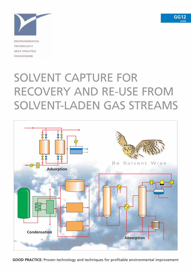
B e S o l v e n t W i s e
GOOD PRACTICE: Proven technology and techniques for profitable environmental improvement
GG12GUIDE
SOLVENT CAPTURE FOR RECOVERY AND RE-USE FROMSOLVENT-LADEN GAS STREAMS
Adsorption
Absorption
Condensation
© Crown copyright. First printed January 1996. This material may be freely reproduced except for sale or advertising purposes.
SOLVENT CAPTURE FORRECOVERY AND RE-USE FROMSOLVENT-LADEN GAS STREAMS
This Good Practice Guide was produced by the
Environmental Technology Best Practice Programme
Prepared with assistance from ENTEC UK Ltd
With particular acknowledgement for contributions from:
Air Products plc
AMEG (UK) Ltd
BOC Gases
QVF Process Systems Ltd
Sutcliffe Croftshaw Ltd
The Environmental Technology Best Practice Programme is a joint Department of Trade and Industryand Department of the Environment initiative managed by AEA Technology through ETSU and theNational Environmental Technology Centre.
The Environmental Technology Best Practice Programme promotes the use of better environmentalpractices that reduce business costs for UK industry and commerce.
The Programme concentrates on two ‘permanent themes’ to achieve its aims:
WASTE MINIMISATIONManagement methods for systematically reducing emissions to land, water and air.
COST-EFFECTIVE CLEANER TECHNOLOGYTechnological solutions for reducing waste at source.
While these themes are applicable to every industrial sector, the Programme supplements them byfocusing on ‘areas of special attention’ which can either be an industrial sector or a particularpollutant.
The Programme provides all areas of industry and commerce with information and advice onenvironmental technologies and techniques. This is achieved through the elements described on theopposite page.
For more information about the Programme please phone the Environmental Helpline on 0800 585794
Proven technology andtechniques for profitable environmental improvement.
Good Practice Guides are handbooks
that provide detailed guidance on
proven technologies and techniques
that save money and reduce waste
and pollution.
Good Practice Case Studies are prime
examples of proven, cost-effective
technologies and techniques that
have already improved environmental
performance. Independent experts
evaluate projects that have been
implemented in industrial companies,
and the details are published in
Programme literature. In return for
co-operating with this process, host
companies are eligible for access
payments of up to £10 000.
New technology andtechniques for profitableenvironmental improvement.
The aim of New Practice is to help UK
industry and commerce to adopt new
technologies and techniques that
save money and reduce waste and
pollution.
New Practice Case Studies are the
first commercial applications of
innovative measures that improve
environmental performance. As with
Good Practice, independent experts
evaluate the projects and the details
are published in Programme
literature. In return for co-operating
with this process, host companies are
eligible for access payments of up to
£50 000.
Tomorrow’s technology andtechniques for profitable environmental improvement.
This is the Programme’s Research
and Development element.
It supports work progressing novel
environmental technologies and
techniques. The results of Future
Practice projects are published to
encourage companies to take up
successful developments.
GOODPRACTICE
NEWPRACTICE
FUTUREPRACTICE
BEST PRACTICE IN ACTIONenvironmental improvements that save money
ENVIRONMENTAL PERFORMANCE GUIDESthe benchmark for profitable environmental improvement
ENVIRONMENTAL HELPLINE 0800 585794the gateway to the Environmental Technology Best Practice Programme
The Programme’s Environmental Helpline has access to a wide range of environmental information. It offers
free advice to companies on technical matters, environmental legislation, conferences and promotional
seminars. For smaller companies, a free counselling visit may be offered at the discretion of the Helpline
Manager.
Environmental Performance Guides contain data on current environmental performance for a particular
industry sector, technology or operation and are compiled on the basis of replies to confidential questionnaires.
The Guides enable individual companies to compare their performance with that of others undertaking similar
operations and to identify potential areas for improvement.
For more information about the Programme please phone the Environmental Helpline on 0800 585794
S U M M A R Y
This Good Practice Guide provides detailed information about proven technologies and techniquesfor the capture, recovery, and subsequent re-use of organic solvents from solvent-laden gas streams.It is intended to help companies consider fully if solvent capture and re-use could be cost effectivefor them and, if so, to select the most appropriate technology for the recovery of solvent from theirprocess emissions.
Different categories of the three main solvent recovery techniques - adsorption, condensation andabsorption (scrubbing) - are considered. For each technology, the Guide discusses:
■ general principles;
■ applicability;
■ advantages and disadvantages;
■ equipment operation and installation;
■ utility requirements;
■ factors affecting capital and operating costs.
In addition, the Guide considers new and emerging technologies such as membrane processes.
The Guide stresses that the best choice is strongly dependent on the nature of the air stream, theproperties of the solvent concerned, and the specific application. The Guide presents informationon measures to improve the cost-effectiveness of solvent capture and re-use. For example, re-usingthe captured solvent, preferably directly, makes recovery much more attractive economically, andlowering the maximum volumetric airflow through a system reduces both the capital and operatingcosts of recovery equipment. An indication of the range of flow rates and solvent concentrations foreach technology is given in the Guide.
Adsorption is an extensively used recovery technique. A range of adsorbents is available, withgranular activated carbon (GAC) the most common choice. Desorption/recovery is carried out eitherby using steam or a hot inert gas, or under vacuum.
Recent developments mean that condensation using a range of coolants and refrigerants is a viablestand-alone option for solvent recovery. It is considered highly suitable for organic solvents withreasonably high boiling points and which are present in appreciable concentrations. Cryogeniccondensation using liquid nitrogen is an option for solvents with low boiling points. It is particularlyeconomic for those companies that use liquid nitrogen on site.
Absorption or scrubbing is particularly suitable for solvents that are readily soluble in water or forhigh boiling point organic compounds. Organic scrubbing liquids are usually regenerated by steamstripping; aqueous ones by distillation.
The last section in the Guide is intended to help highlight the issues that can determine whether ornot solvent capture and re-use will be a viable option at your site.
C O N T E N T S
Section Page
1 Introduction 1
1.1 Target processes 1
1.2 Making solvent capture more cost-effective 2
2 Technology selection 4
2.1 Factors affecting technology selection 4
2.2 Technology capabilities 5
3 Adsorption and associated techniques 6
3.1 General principles 6
3.2 Adsorption 7
3.3 Desorption/recovery 10
3.4 Continuous adsorption-desorption processes 13
3.5 Adsorption capture systems 14
3.6 Operation and installation 15
3.7 Cost factors 17
3.8 Summary 18
4 Condensation and associated techniques 19
4.1 General principles 19
4.2 Technical considerations 19
4.3 Coolant/refrigerant condensation 20
4.4 Cryogenic condensation 22
4.5 Closed-cycle inert gas condensation 24
4.6 Operation and installation 25
4.7 Cost factors 27
4.8 Summary 27
5 Absorption (scrubbing) and associated techniques 28
5.1 General principles 28
5.2 Absorption (scrubbing) 29
5.3 Desorption 31
5.4 Re-use of solvent 31
5.5 Operation and installation 32
5.6 Cost factors 33
5.7 Summary 34
6 Recent developments 35
6.1 Membrane processes 35
6.2 Plasticiser/solvent recovery system 35
6.3 Adsorbent regeneration 36
6.4 Condensation systems 36
6.5 Absorption systems 36
7 What Next? 37
Appendices
Appendix 1 Equipment suppliers and solvent recovery companies in the UK 39
Appendix 2 Bibliography 41
1
I N T R O D U C T I O N1
section
1
This Good Practice Guide is intended to both promote awareness of and provide detailedinformation about proven technologies for the capture, recovery, and subsequent re-use of solventsfrom solvent-laden gas streams. The following aspects are discussed for each of the three mainsolvent recovery techniques - adsorption, condensation and absorption (scrubbing):
■ general principles;
■ applicability;
■ advantages and disadvantages;
■ equipment operation and installation;
■ utility requirements;
■ factors affecting capital and operating costs.
Volatile organic compound (VOC) emissions from industry are subject to statutory control. A firststep to compliance should be a review of your solvent consumption to minimise use (see GoodPractice Guide GG13, Cost-effective Solvent Management). If abatement equipment is required forcompliance, solvent capture and re-use should be considered. Given the information in this Guide,it is hoped that the option of recovering solvent from solvent-laden gas streams will be fullyconsidered as an economic means of VOC emissions to the atmosphere.
For advice and information on current legislation governing VOC emissions, readers are advised tocontact the Environmental Helpline on 0800 585794.
1.1 TARGET PROCESSES
This Guide is intended to be of use to any company considering solvent capture and re-use fromsolvent-laden gas streams. It has particular relevance to the following manufacturing processes andindustrial installations:
■ printing processes;
■ surface cleaning operations;
■ coating processes;
■ manufacture of coatings, varnishes, inks and adhesives;
■ tank vents.
This Guide will be relevant for those considering new abatement equipment on existing plant, thoseupgrading abatement equipment, and those considering new process plant.
2
section
1
1.2 MAKING SOLVENT CAPTURE MORE COST-EFFECTIVE
The following considerations can significantly improve the cost-effectiveness of solvent recovery.
1.2.1 Re-use of the solvent
Key points to consider on the options for solvent re-use include:
■ the number of solvents in the air stream;
■ the miscibility of the solvents in water and with each other;
■ the purity of solvent needed for re-use in the process;
■ the possibility of re-using the solvent mixture without any further separation.
Single solvent systems are the easiest to recover for re-use. For example, a plant where thecondenser is positioned immediately above the reactor vessel allows the condensed solvent mixtureto return directly to the reactor.
With solvent blends of a constant composition, it is possible to recover the blend in the sameproportions. This can then be re-used without further separation.
In general, capture from single solvent streams is most attractive economically. However, recoveryand re-use from mixtures of up to three solvents may be viable, particularly if one is present at highconcentrations and expensive to purchase new. Where mixtures need to be separated into theirindividual components, larger users are more likely to find the necessary separation equipment cost-effective.
There are many factors to be taken into account in assessing the economics of solvent capture andre-use. It is important that the full value of the recovered solvent, the cost of any treatment processand the cost of buying fresh solvent, are all taken into account when considering the economics ofsolvent recovery. In addition, if the captured solvent is sent to a solvent recovery company, and notfor disposal, a credit on your total solvent consumption will be applied, and this could enable you tofall below the authorisation limit.
Ask yourself if you could improve the cost-effectiveness of solvent recovery in your company.
■ How are various solvents used in the manufacturing process? Could the number of differentsolvents used be reduced by substituting a common solvent capable of achieving the sametasks? Fewer solvent types will make capture and re-use more viable.
■ Could the recovered solvent mixture be re-used in the process itself or for other duties? Usingrecovered solvent as a cleaning solvent or for thinning paint, ink, etc, will offset the cost ofnew materials. Such duties may not consume all the recovered solvent; this, too, should betaken into account.
■ Could your company use a secondary solvent recovery and recycling company? (Details ofsuch companies are available from the Environmental Helpline on 0800 585794). Thesecompanies offer a range of services which may give a significant value to the captured solvent,so reducing your operating costs. These services include:
– the recovery of solvents to an agreed specification for return and re-use;
– supplying solvent blends for use by other organisations;
– purification of a single recovered solvent to the required specification.
■ Could the recovered solvent mixture be used by another company? Waste exchangeorganisations try to connect companies with specific wastes with other companies that maybe able to use these wastes. (Details are available from the Environmental Helpline on0800 585794). Again, this has the benefit of reducing net costs by giving a value to therecovered solvent.
3
section
1
1.2.2 Airflow rates
The size and cost of a solvent recovery system is usually dictated by the volumetric airflow. Thesuitability and efficiency of a recovery technology is highly dependent on the concentration ofsolvents in the air stream.
Lowering the maximum volumetric airflow reduces capital expenditure on equipment andassociated operating costs such as fan power, utility requirements, etc. The resulting increase insolvent concentration also improves the efficiency of the recovery system. The safety and processconstraints of the production system must, however, always be taken into account when increasingsolvent concentrations.
The maximum airflow can be reduced by:
■ Air recirculation.
■ Improved design and optimisation of extraction and ventilation systems so that solventvapour is removed in a smaller volume of air. Operator safety must not, however, becompromised.
■ Fan control (when airflow and solvent emission rates are variable).
■ Avoiding excess dilution by not mixing the air stream with other non-solvent processemissions.
■ Using inert gases; this allows a reduction of airflow because VOC concentrations can behigher without flammability problems.
■ Ensuring that the fan is not excessively oversized.
Significant savings are achievable with these measures. For new applications, such measures canimprove the overall economics of the capture and re-use option and, for existing recovery plants,can provide a short payback on capital expenditure.
4
section
2
T E C H N O L O G Y S E L E C T I O N2
Selecting the most appropriate technique for the recovery of solvent from a solvent-laden air streamdepends on a number of factors. This Section is intended to be a quick reference guide to thecriteria used to select a particular solvent recovery system. The following sections give details abouteach technique.
2.1 FACTORS AFFECTING TECHNOLOGY SELECTION
The following are factors that affect the selection of a solvent recovery technology.
2.1.1 Air stream
The specific factors relating to the nature of the air stream include:
■ The volumetric airflow rate (minimum, maximum and average figures) and time dependency.This largely dictates the capital cost of the recovery equipment.
■ The minimum, maximum and average concentration of the solvent(s) in the air stream.
■ Whether the air stream contains a single solvent or a mixture of solvents.
■ The presence of impurities, such as particulate matter, which may foul recovery equipment.
■ The temperature and humidity of the air stream.
2.1.2 Solvent properties
The following solvent properties are important:
■ boiling and freezing points;
■ solubility in water and other liquids;
■ whether the solvents form constant-boiling mixtures with water;
■ adsorption capability;
■ hazards, eg flash point, ignition temperature, upper and lower explosive limits, etc.
2.1.3 Industrial application
The particular industrial application also has a major influence on the selection of recoveryequipment. Factors include:
■ value of recovered material;
■ recovery targets;
■ separation/purification steps needed to produce solvent suitable for re-use;
■ availability of on-site services, eg electricity, steam, cooling water, nitrogen, and effluenttreatment facilities;
■ whether the industrial process is already contained or whether space considerations/processconfiguration would permit the installation of a closed circuit system;
■ whether the recovery plant is part of a new process installation or a retrofit;
■ the location and space available for siting the recovery plant.

5
section
2
2.2 TECHNOLOGY CAPABILITIES
The technical factors listed in Section 2.1 are important in selecting the appropriate techniques fora particular solvent recovery application. Table 1 shows the approximate range of flow rates andsolvent concentrations that each technology can handle. These are indicative figures only.
Technology Flow rates (m3/hr) Solvent concentrations (mg/m3)
Adsorption/desorption 100 - 500 000 500 - 10 000
Adsorption capture systems 10 - 1 000 10 - 10 000
Coolant/refrigerant condensation 100 - 50 000 5 000 - 100 000
Cryogenic condensation 10 - 5 000 5 000 - 50 000
Absorption (scrubbing) 100 - 20 000 500 - 10 000
Table 1 Technology capabilities in terms of flow-rate and solvent concentration
6
section
3
A D S O R P T I O N A N D A S S O C I AT E DT E C H N I Q U E S
3
Solvent recovery by adsorption is a proven technology, which has been used since the 1930s, and isstill extensively used. It is suitable for use in applications where:
■ solvents are readily adsorbed onto activated carbon or other adsorbents;
■ contaminant and humidity levels in the air stream are low.
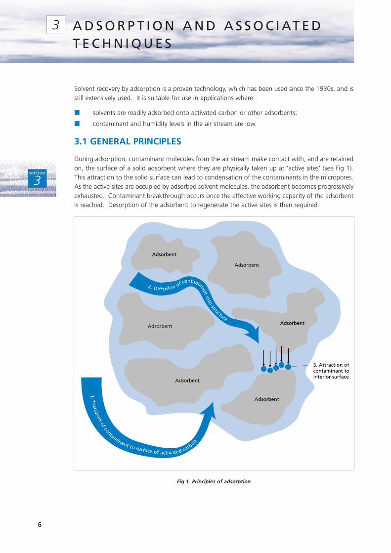
3.1 GENERAL PRINCIPLES
During adsorption, contaminant molecules from the air stream make contact with, and are retainedon, the surface of a solid adsorbent where they are physically taken up at ‘active sites’ (see Fig 1).This attraction to the solid surface can lead to condensation of the contaminants in the micropores.As the active sites are occupied by adsorbed solvent molecules, the adsorbent becomes progressivelyexhausted. Contaminant breakthrough occurs once the effective working capacity of the adsorbentis reached. Desorption of the adsorbent to regenerate the active sites is then required.
Fig 1 Principles of adsorption
2. Diffusion of contaminantinto
structure
1. Transportof contaminant to surface of activated carb
on
3. Attraction ofcontaminant tointerior surface
Adsorbent
Adsorbent
Adsorbent
Adsorbent
Adsorbent
Adsorbent
7
section
3
Adsorption generally releases heat; desorption requires heat to purge the adsorbent of solvent.
Adsorption and desorption capacities depend on several factors, including:
■ the choice and quantity of adsorbent;
■ the concentration and nature of the solvent-laden gas stream;
■ the process temperature, pressure and gas flow rate.
Adsorption capacity generally increases with:
■ increasing molecular weight/boiling point of the adsorbed compound;
■ reducing polarity;
■ increasing cyclic (rather than straight chain) structure of organic solvent.
As the adsorption capacity increases, the size and cost of a unit needed to achieve a given level ofadsorption decreases.
3.2 ADSORPTION
3.2.1 Adsorbents
Typical adsorbents are highly porous, granular solids with large surface-to-volume ratios. They aresized to provide low resistance to gas flow. Examples include:
■ granular activated carbon (GAC);
■ molecular sieve zeolites;
■ macroporous polymer particles;
■ silica gel;
■ sodium-aluminium silicates.
GAC is the most commonly used adsorbent.
Zeolites can be manufactured with precise pore sizes, allowing selective adsorption of somecompounds. As zeolites adsorb little water, they can be used at higher humidities than GAC.Zeolites are non-combustible, making them suitable for use with compounds that might representa fire risk with GAC, eg cyclohexanone. However, zeolites cost considerably more than GAC; theiruse, to date, has been mainly where GAC is unsuitable.
Polymer adsorbents are particularly suited to continuous adsorption-desorption processes (seeSection 3.4).
Adsorbents can hold up to 30% weight-for-weight (w/w) of solvent. Optimum systems are usuallydesigned to achieve between 5 - 10% w/w cyclic efficiency, ie the amount of solvent adsorbedduring the complete adsorption/desorption cycle.
3.2.2 Solvent compatibility
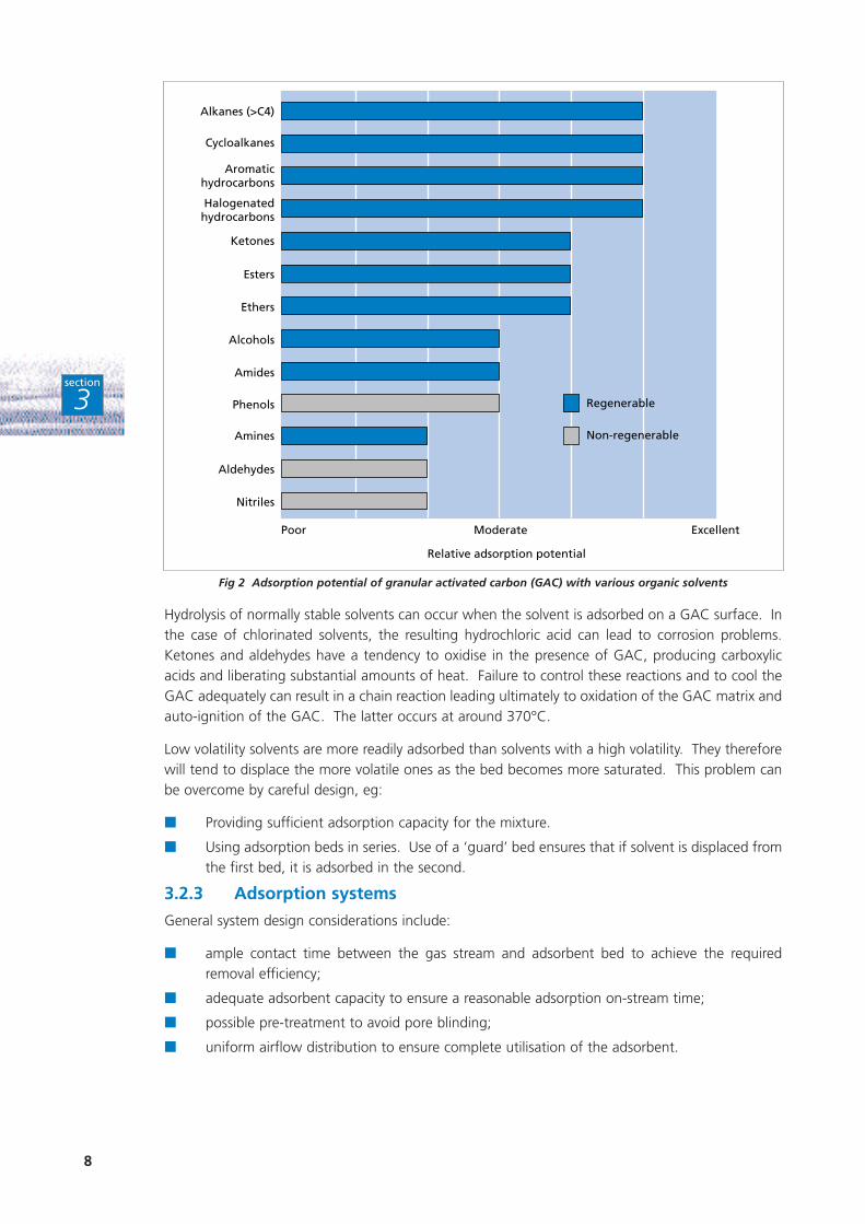
While a wide range of solvents can be removed by adsorption (see Fig 2), not all are recoverable bydesorption. Desorption of high boiling point solvents (higher than 200°C) requires more energy.Phenols and nitriles are particularly difficult to desorb. Cyclohexanone is prone to polymerise whenadsorbed, significantly reducing adsorbent life and creating a potential flammability hazard.
8
section
3
Fig 2 Adsorption potential of granular activated carbon (GAC) with various organic solvents
Hydrolysis of normally stable solvents can occur when the solvent is adsorbed on a GAC surface. Inthe case of chlorinated solvents, the resulting hydrochloric acid can lead to corrosion problems.Ketones and aldehydes have a tendency to oxidise in the presence of GAC, producing carboxylicacids and liberating substantial amounts of heat. Failure to control these reactions and to cool theGAC adequately can result in a chain reaction leading ultimately to oxidation of the GAC matrix andauto-ignition of the GAC. The latter occurs at around 370°C.
Low volatility solvents are more readily adsorbed than solvents with a high volatility. They thereforewill tend to displace the more volatile ones as the bed becomes more saturated. This problem canbe overcome by careful design, eg:
■ Providing sufficient adsorption capacity for the mixture.
■ Using adsorption beds in series. Use of a ‘guard’ bed ensures that if solvent is displaced fromthe first bed, it is adsorbed in the second.
3.2.3 Adsorption systems
General system design considerations include:
■ ample contact time between the gas stream and adsorbent bed to achieve the requiredremoval efficiency;
■ adequate adsorbent capacity to ensure a reasonable adsorption on-stream time;
■ possible pre-treatment to avoid pore blinding;
■ uniform airflow distribution to ensure complete utilisation of the adsorbent.
Poor Moderate Excellent
Alkanes (>C4)
Cycloalkanes
Aromatichydrocarbons
Halogenatedhydrocarbons
Ketones
Esters
Ethers
Alcohols
Amides
Phenols
Amines
Aldehydes
Nitriles
Regenerable
Non-regenerable
Relative adsorption potential
9
section
3
Other important parameters are:
■ The temperature of the air stream (cooler air streams are more efficient).
■ The moisture content of the air stream. The performance of adsorbents (particularly GAC) issensitive to the moisture content of the air. Once the relative humidity of the stream exceeds60%, the adsorption capacity is significantly reduced owing to the microporous structure ofthe adsorbent filling with water.
Potentially necessary pre-treatments include:
■ pre-cooling the air to improve adsorption efficiency;
■ using filters or mist eliminators to remove solids or liquids (droplets or aerosols) which cancause plugging of the adsorbent;
■ using a sacrificial layer of adsorbent to remove components with boiling points greaterthan 150 - 200°C that would be collected but not removed (due to the excess energyrequirement) during bed regeneration.
3.2.4 Fixed bed process
This process variant involves the alternate batch-wise adsorption and desorption of the solvent in afixed bed of adsorbent. More than one adsorber is required for continuous operation. Twin bedsare typical, with one bed adsorbing the solvent while the other is being regenerated. Third or fourthbeds may be required if:
■ the time required for the adsorption phase differs from that for the desorption phase;
■ stand-by capacity is required.
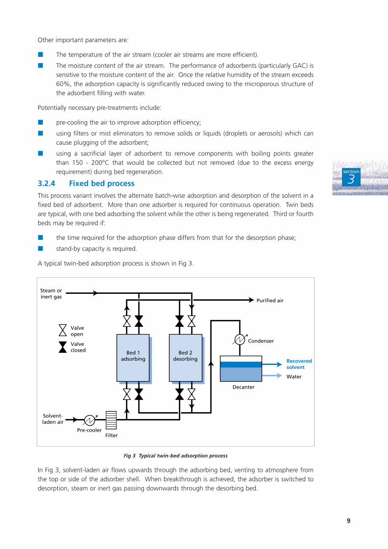
A typical twin-bed adsorption process is shown in Fig 3.
Fig 3 Typical twin-bed adsorption process
In Fig 3, solvent-laden air flows upwards through the adsorbing bed, venting to atmosphere fromthe top or side of the adsorber shell. When breakthrough is achieved, the adsorber is switched todesorption, steam or inert gas passing downwards through the desorbing bed.
Bed 1adsorbing
Bed 2desorbing
Condenser
Recoveredsolvent
Water
Decanter
Solvent-laden air
Steam orinert gas
Purified air
FilterPre-cooler
Valveopen
Valveclosed
10
section
3
Adsorption cycles are controlled by one of the following:
■ a gas analyser using a set solvent breakthrough concentration to switch adsorbers;
■ a calculated fixed time cycle.
3.2.5 Activated carbon mat filter
An alternative to GAC is the activated carbon mat filter. The filter comprises a circular filter elementconsisting of a non-woven web of fine activated carbon filaments. Solvent vapour is adsorbedwithin the very fine micropores of the carbon. The different physical nature of the carbon allows ahigher specific surface area to packed volume ratio to be achieved, ie there are more active sites perunit volume. Higher solvent loadings can thus be achieved per unit mass of carbon cloth comparedto GAC. This allows for a more economical use of steam and a reduction in the total volume ofeffluent produced by the plant.
Such systems can be used to recover a wide range of solvents, including polar compounds andketones. Hot spot formation is avoided due to the short cycle times. However, activated carbon matfilters are typically 100 times more expensive than GAC.
3.3 DESORPTION/RECOVERY
Desorption - the reverse of adsorption - can be carried out by:
■ steam desorption;
■ inert gas desorption;
■ vacuum desorption.
These three methods, which are shown in simplified flow charts in Fig 4, are described in more detailbelow.
For safety reasons, hot air desorption is not, in general, a preferred technique for solvent recovery.However, it can be used when solvent concentrations are low (hundreds of parts per million (ppm)),for example in adsorption/desorption processes which are used to concentrate emission streamsprior to further treatment. More recent developments include continuous adsorption-desorptionprocesses (see Section 3.4).
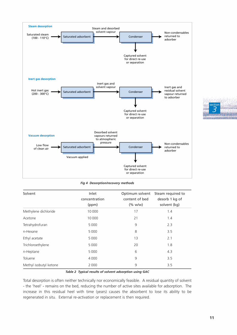
3.3.1 Steam desorption
This relatively cheap and often simple method (see Fig 4) is the most widely used regenerationtechnique. It uses saturated steam at temperatures of 100 - 110°C to heat the adsorbent by steamcondensation. Initially, all the steam is used to heat both adsorbent and adsorber to the steamsaturation temperature at the existing vessel pressure. Desorption of the adsorbed solvents does notstart until the adsorbent bed has warmed up.
During the desorption process, some steam condenses on the adsorbent to deliver the energyneeded for solvent desorption. Most of the steam, however, flows through the adsorbent removingthe desorbed solvent. Further reduction of the residual solvent load is obtained by the flushing effectof the steam and the declining solvent partial pressure.
Typical results, for an exit concentration of 20 ppm, of a solvent adsorption/desorption system usingGAC are shown in Table 2. Exit concentrations can be as low as 5 ppm.
11
section
3
Solvent Inlet Optimum solvent Steam required to
concentration content of bed desorb 1 kg of
(ppm) (% w/w) solvent (kg)
Methylene dichloride 10 000 17 1.4
Acetone 10 000 21 1.4
Tetrahydrofuran 5 000 9 2.3
n-Hexane 5 000 8 3.5
Ethyl acetate 5 000 13 2.1
Trichloroethylene 5 000 20 1.8
n-Heptane 5 000 6 4.3
Toluene 4 000 9 3.5
Methyl isobutyl ketone 2 000 9 3.5
Table 2 Typical results of solvent adsorption using GAC
Total desorption is often neither technically nor economically feasible. A residual quantity of solvent- the ‘heel’ - remains on the bed, reducing the number of active sites available for adsorption. Theincrease in this residual heel with time (years) causes the absorbent to lose its ability to beregenerated in situ. External re-activation or replacement is then required.
Saturated adsorbent Condenser
Captured solventfor direct re-use
or separation
Saturated adsorbent Condenser
Captured solventfor direct re-use
or separation
Saturated adsorbent Condenser
Captured solventfor direct re-use
or separation
Non-condensablesreturned toadsorber
Non-condensablesreturned toadsorber
Inert gas andresidual solventvapour returnedto adsorber
Steam and desorbedsolvent vapour
Inert gas andsolvent vapour
Desorbed solventvapours returnedto atmospheric
pressure
Saturated steam(100 - 110°C)
Hot inert gas(200 - 300°C)
Low flowof clean air
Vacuum applied
Steam desorption
Inert gas desorption
Vacuum desorption
Fig 4 Desorption/recovery methods
12
section
3
The desorbed vapours, which are condensed in conventional water-cooled or air-cooled heatexchangers, are collected for re-use or further purification. Uncondensed vapours from the desorberare recycled into the incoming air stream. Following steam desorption, the bed should be dried withair and allowed to cool before adsorption recommences.
Steam is the preferred regenerating agent for solvents that are immiscible with water; the solventphase and the steam condensate can be readily separated in a decanter. Both the concentration ofwater in the solvent phase and the concentration of solvent in the aqueous phase depend on thedegree of immiscibility and the temperature. Provided a small amount of water in the solvent phasedoes not affect the manufacturing process, the solvent may be re-used direct from the decanter. Theaqueous phase can be treated as necessary.
Distillation is normally used to separate water-soluble solvents - eg alcohols or esters - and multi-solvent mixtures that cannot be separated by decantation. The large heat input needed fordistillation may result in high operating costs. Distillation can be performed:
■ on-site;
■ off-site by a solvent recovery company (contact the Environmental Helpline on 0800 585794for more information).
Water-soluble solvents that form constant-boiling mixtures are not readily separated. They requiredistillation, followed by further purification, to obtain re-usable solvents.
3.3.2 Inert gas desorption
Nitrogen is the inert gas typically used for this method (see Fig 4), which is particularly suitable foruse with water-soluble solvents.
Oxygen levels in the desorption loop are first reduced by purging with dry nitrogen. Hot inert gasat 200 - 300°C is then circulated. The hot inert gas preferentially desorbs the moisture capturedfrom the air by the adsorbent. This water is subsequently removed by drying the gas with amolecular sieve. Once the water is desorbed, hot, dry inert gas desorbs the solvent. The desorbedsolvent is condensed from the carrier gas, ready for direct re-use.
Heat removed during condensation can be transferred back to the gas heater by a heat pump, whilethe hot gas can be recycled through the adsorber. Once the bed is fully desorbed, gas heatingshould cease and the circulating gas allowed to cool the bed. The heat removed from the bed canbe used to regenerate the molecular sieves.
If a low moisture content is acceptable in the recovered solvent, then it is not necessary to dry thecarrier gas using molecular sieves. The solvent can then be recycled direct from the condenser.Further separation is required if:
■ any hydrolysis of the solvent occurs;
■ the water content is significant;
■ a mixture of solvents is recovered.
This separation is usually achieved by distillation.
The main advantage of inert gas desorption is that the recovered solvent has a low water contentand may be fit for direct re-use.
3.3.3 Vacuum desorption
In this method (see Fig 4), the reduced pressure causes the adsorbed solvent to vaporise from theadsorbent pores. One example is known as the ‘pressure swing adsorber’.
13
section
3
In systems using vacuum desorption, the adsorbent beds are designed to retain the heat releasedduring the adsorption step for use in a subsequent regeneration step. During regeneration, avacuum is created around the bed. This causes the adsorbed solvent to re-vaporise and desorb fromthe adsorbent. The desorption process is bolstered by the heat of adsorption retained in the bed.The solvents desorbed from the bed are removed by back-purging with a small portion of the cleanvent stream.
The concentrated desorbed solvent vapours are returned to atmospheric pressure and condensed;non-condensables are returned to the on-line adsorber.
Vacuum regeneration works best when recovering high volatility solvents from high-capacityadsorbents. However, the technique usually has higher equipment costs than other methods.
3.4 CONTINUOUS ADSORPTION-DESORPTION PROCESSES
Continuous systems eliminate the need for duplicate equipment as the adsorption and desorptionstages are carried out in the same unit.
The solvent-laden air stream, which is introduced at the base of the adsorption section, flowsupwards through perforated trays arranged one above another. The solvent is adsorbed and thetreated air discharged to atmosphere.
Regenerated adsorbent is fed continuously by a conveyor to the top adsorber tray, from where itflows downwards from tray to tray. The saturated adsorbent on the lowest tray passes into theregeneration section via a nitrogen gas lock separating the two sections. The adsorbent then travelsdownwards through the desorber tubes. The adsorbent is indirectly heated to desorptiontemperature and desorbed with an inert gas, eg nitrogen. The regenerated adsorbent is cooled andreturned pneumatically to the top adsorber tray, while the hot inert gas stream is cooled in anexternal condenser to remove solvent. By adjusting the rate at which the regenerated adsorbent isreturned to the adsorber, its retention time in the adsorber can be controlled.
The recovered solvent, which is virtually water-free, can be directly re-used. Steam can be usedinstead of an inert gas when water-insoluble solvents are being recovered. The condensedsteam/solvent separation is performed in a decanter.
The main problems with continuous systems are due to their greater complexity compared totraditional systems. Continuous adsorption-desorption systems require a large quantity ofadsorbent, with allowance made for any attrition and breakdown of the adsorbent.
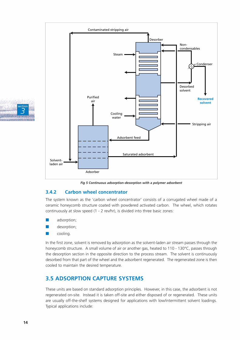
3.4.1 Polymer adsorbent systems
One variation is to use a polymer adsorbent instead of activated carbon (see Fig 5). In this systemheated air is used in the desorption process. The polymer adsorbent, which is intended for airstreams with low solvent concentrations, has the following advantages:
■ durability;
■ unaffected by high humidity;
■ does not catalyse the degradation of unstable solvents;
■ regenerated under very mild conditions;
■ high purity solvents recovered.
Polymer adsorbents are, however, ten times more expensive than GAC. They are suitable for usewith most common solvents, except for very polar compounds and those with low boiling points,eg methanol and methyl chloride.
14
section
3
Fig 5 Continuous adsorption-desorption with a polymer adsorbent
3.4.2 Carbon wheel concentrator
The system known as the ‘carbon wheel concentrator’ consists of a corrugated wheel made of aceramic honeycomb structure coated with powdered activated carbon. The wheel, which rotatescontinuously at slow speed (1 - 2 rev/hr), is divided into three basic zones:
■ adsorption;
■ desorption;
■ cooling.
In the first zone, solvent is removed by adsorption as the solvent-laden air stream passes through thehoneycomb structure. A small volume of air or another gas, heated to 110 - 130°C, passes throughthe desorption section in the opposite direction to the process stream. The solvent is continuouslydesorbed from that part of the wheel and the adsorbent regenerated. The regenerated zone is thencooled to maintain the desired temperature.
3.5 ADSORPTION CAPTURE SYSTEMS
These units are based on standard adsorption principles. However, in this case, the adsorbent is notregenerated on-site. Instead it is taken off-site and either disposed of or regenerated. These unitsare usually off-the-shelf systems designed for applications with low/intermittent solvent loadings.Typical applications include:
Contaminated stripping air
Steam
Coolingwater
Desorber
Non-condensables
Desorbedsolvent
Condenser
Recoveredsolvent
Stripping air
Adsorbent feed
Saturated adsorbent
Adsorber
Solvent-laden air
Purifiedair
15
section
3
■ storage tank venting;
■ treatment of outlet air from stripping towers (depending on humidity levels).
Such adsorption systems typically consist of GAC in a deep, but compact, canister. Efficient contactbetween the gas and GAC is achieved by using a perforated distribution plate. This, together withan extended contact time, results in high efficiency adsorption but with a low pressure drop.
Both installation and operation are straightforward owing to the system’s simple design. Operationmerely involves routine monitoring of outlet concentrations. Once breakthrough occurs, continuityof operation is maintained by replacing either the whole unit or just the GAC. These operations arenormally carried out by the supplier.
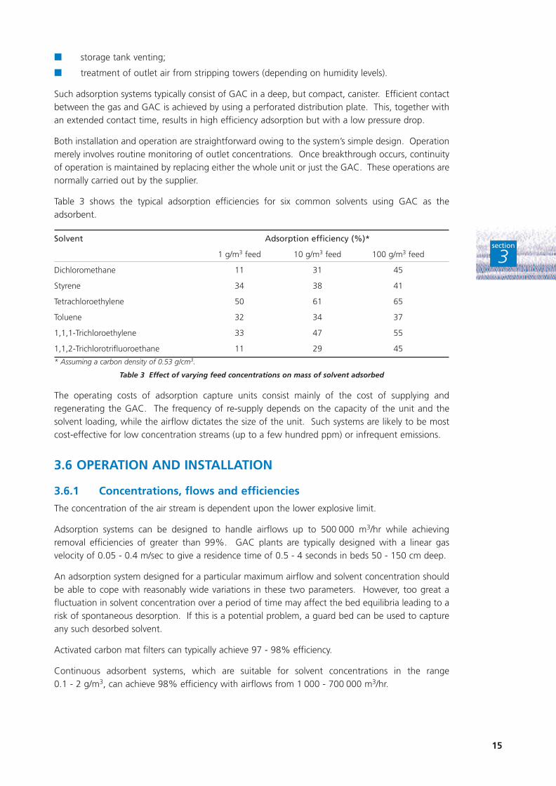
Table 3 shows the typical adsorption efficiencies for six common solvents using GAC as theadsorbent.
Solvent Adsorption efficiency (%)*
1 g/m3 feed 10 g/m3 feed 100 g/m3 feed
Dichloromethane 11 31 45
Styrene 34 38 41
Tetrachloroethylene 50 61 65
Toluene 32 34 37
1,1,1-Trichloroethylene 33 47 55
1,1,2-Trichlorotrifluoroethane 11 29 45
* Assuming a carbon density of 0.53 g/cm3.
Table 3 Effect of varying feed concentrations on mass of solvent adsorbed
The operating costs of adsorption capture units consist mainly of the cost of supplying andregenerating the GAC. The frequency of re-supply depends on the capacity of the unit and thesolvent loading, while the airflow dictates the size of the unit. Such systems are likely to be mostcost-effective for low concentration streams (up to a few hundred ppm) or infrequent emissions.
3.6 OPERATION AND INSTALLATION
3.6.1 Concentrations, flows and efficiencies
The concentration of the air stream is dependent upon the lower explosive limit.
Adsorption systems can be designed to handle airflows up to 500 000 m3/hr while achievingremoval efficiencies of greater than 99%. GAC plants are typically designed with a linear gasvelocity of 0.05 - 0.4 m/sec to give a residence time of 0.5 - 4 seconds in beds 50 - 150 cm deep.
An adsorption system designed for a particular maximum airflow and solvent concentration shouldbe able to cope with reasonably wide variations in these two parameters. However, too great afluctuation in solvent concentration over a period of time may affect the bed equilibria leading to arisk of spontaneous desorption. If this is a potential problem, a guard bed can be used to captureany such desorbed solvent.
Activated carbon mat filters can typically achieve 97 - 98% efficiency.
Continuous adsorbent systems, which are suitable for solvent concentrations in the range 0.1 - 2 g/m3, can achieve 98% efficiency with airflows from 1 000 - 700 000 m3/hr.
16
section
3
3.6.2 Utilities and consumables
The main utilities required for adsorption systems are:
■ steam or hot oil to heat the desorbing inert gas, depending on the desorption method;
■ cooling water for condensing desorbed solvent;
■ electricity to power fans, pumps, etc.
As a general rule, steam regeneration for GAC requires a steam to solvent ratio between 1.5:1 and6:1 (w/w). If desorption is carried out using an inert gas, eg nitrogen, operating experience suggeststhat 35 m3 of nitrogen is needed to desorb one tonne of solvent.
Steam requirements for an activated carbon mat filter can be expected to be at least twice that ofGAC or polymer adsorption systems, ie a steam to solvent ratio of between 6:1 and 12:1 (w/w).
It is not possible to predict the life of the adsorbent. This depends on the level of adsorptioninhibitors in the system, eg:
■ particulates;
■ moisture (humidity);
■ high molecular weight solvents.
Although the adsorbent can be re-activated by thermal treatment and re-used, re-activated GAC isnot generally as efficient as new GAC.
3.6.3 Control and operation
Adsorption systems are typically controlled by a programmable logic controller, with new systemsbased on breakthrough sequencing of the beds. When the emission level from an operating bedreaches a pre-set level (ie at adsorbent breakthrough), the beds are switched over and regenerationstarts. This is energy efficient as desorption is always performed on a saturated bed.
Beds are also switched by a back-up timer to avoid oversaturation. Given a constant airflow andsolvent concentration, an automatic timer system is more cost-effective. Such systems are normallydesigned with approximately equal adsorption and desorption times.
Subject to consideration of flammable hazards, control systems can be designed to allow a solventconcentration of up to 40% of the lower explosive limit. This minimises both fan power and steamconsumption (at higher inlet solvent concentrations, the capacity of the adsorbent is higher).
If flow rates and solvent loadings are variable, power requirements can be optimised by fittingcontrol dampers or variable speed drives for the fan. For example, in a printing process drying cyclewhere 40 - 50% of the solvent is emitted in the first hour, the controls are set to maintain a constantsolvent concentration with a variable airflow. The flow rate is therefore reduced as the solventconcentration decreases.
Where GAC is used to adsorb ketones, careful start-up and shut-down procedures must be followedto minimise the risk of bed fires. If insufficient desorption and cooling has been carried out at shut-down, ketone oxidation can result in pockets of heat (‘hot spots’) within the bed. A chain reactionfollowed by a bed fire may result.
With standard control systems that include automatic alarms and shut-down capabilities, staffrequirements are minimal, merely consisting of periodic checks of gauges, etc, once or twice a day.Larger systems may need staff attention for about an hour a day.
17
section
3
3.6.4 Maintenance
Maintenance is minimal as there are few moving parts. It is typically concerned with pumps, fans,etc, plus occasional adsorbent sampling to check its remaining life.
3.6.5 Ease of retrofitting
Provided sufficient space is available, retrofitting an adsorption system to an existing manufacturingprocess is generally straightforward. The space requirement of a continuous adsorption/desorptionunit is approximately 25% that of a two-bed adsorber system.
3.7 COST FACTORS
The following factors influence the cost of an adsorption recovery system.
3.7.1 Capital cost
Emission flow rate. This influences the overall size of the system.
Solvent type. This dictates the choice of adsorbent. For example, GAC is considerably cheaper thanactivated carbon mat filters or polymeric adsorbents.
Solvent adsorption efficiency and solvent concentration. Both influence the quantity of adsorbentrequired.
Solvent mixtures. Multi-component solvent streams are likely to require more complex separationtechniques.
Solvent solubility. The more soluble the solvent is in water, or other components present in the airstream, the more complex the separation technique likely to be required.
3.7.2 Operating costs
Emission flow rate. This dictates utility requirements.
Solvent loading. This influences both the use of utilities in the adsorption/desorption cycle,eg steam, and the rate of adsorbent degradation.
Presence of impurities. Particulates and high boiling point solvents will reduce the life of theadsorbent.
Ease of solvent desorption. High boiling point solvents require higher temperatures for desorption,but condense more readily.
Solvent mixtures. More energy-intensive separation techniques are likely to be required.
Solvent solubility. The more soluble the solvent is in water, or other components present in thestream, the more energy-intensive the separation technique likely to be required.
18
section
3
3.8 SUMMARY
■ Adsorption-based techniques are extensively used for solvent recovery.
■ GAC is the most common adsorbent. Others include zeolites and polymer particles.
■ Adsorption capacity increases with increasing molecular weight and boiling point ofsolvent, but decreases with increasing polarity. Activated carbon adsorption is impairedwhen the gas stream has a humidity above 60%.
■ Desorption can be carried out by using steam, a hot inert gas (eg nitrogen) or undervacuum (reduced pressure). Steam desorption of water-soluble solvents may necessitatemore complex separation techniques for solvent recovery.
■ Adsorption/desorption systems can be:
– fixed beds operated in alternate modes;
– systems where the adsorbent is continuously conveyed between the adsorber anddesorber.
■ Contaminants such as particulates and high boiling point solvents significantly reduceadsorbent life.
■ Adsorption capture systems can represent a highly practical means of eliminatingemissions from intermittent sources.
■ Changing from air to inert gas allows the airflow rate to be decreased and solventconcentrations increased without compromising safety. Changing the airflow in this waywill reduce operating costs, thus making solvent capture and re-use more cost-effective.
19
C O N D E N S AT I O N A N DA S S O C I AT E D T E C H N I Q U E S
4
section
4
Condensation systems have traditionally been considered useful preliminary recovery units to reducea high solvent loading prior to further recovery, eg using an activated carbon adsorption bed. Whilethis remains a feasible arrangement, developments in both heat exchanger systems and use of lowtemperature fluids mean that condensation systems are now a viable stand-alone option for solventrecovery.
While conventional condensation techniques are most suitable for solvents with a reasonably highvapour pressure, cryogenic condensation is able to cope with all solvents irrespective of their vapourpressures.
4.1 GENERAL PRINCIPLES
Solvent vapours only remain in the gas phase up to a maximum concentration determined by thesolvent vapour pressure at the temperature concerned. The maximum amount of solvent that canbe held in a unit volume of air at equilibrium under stationary conditions is referred to as thesaturation concentration. This concentration can be calculated from the solvent’s vapour pressureand molecular weight. The temperature at which this saturation concentration is reached is knownas the dew point. If the temperature falls below the dew point, some of the solvent must revertto the liquid phase until the saturation concentration (ie equilibrium) in the gas phase is reached atthe lower temperature. If the vapour phase consists of a solvent mixture, allowance must be madefor the actual phase equilibria of the individual components. No simple relationship exists for thesaturation concentration of the system under such conditions.
This physical relationship forms the basis for solvent recovery by condensation.
In practice, there are technical and economic limits to the application of condensation to solventrecovery. If the concentration of the solvent vapour is very low, the temperature may need to belowered significantly before condensation commences. This may require temperatures that aredifficult to attain. Problems with freezing may occur, particularly when solvent blends arecondensed, due to the differential freezing points within a solvent mixture. Frozen solvent on theheat transfer surface impedes heat transfer and may block the tubes, thus decreasing thecondensation rate. Furthermore, water vapour below its freezing point forms an amorphous depositon the surfaces of heat exchangers, impeding heat transfer.
Minimising the non-condensable gas content of the air stream increases the practicality andeconomic attractiveness of condensation. Vapour streams which are some way away from their dewpoints generally cost more to condense than those fairly close to their dew points.
4.2 TECHNICAL CONSIDERATIONS
Although condensation systems can recover almost any solvent, the feasibility of condensation as arecovery technique depends on the condensing temperature required. Generally, the lower theboiling point of the solvent, the more difficult it is to recover. Cryogenic condensation is an optionif condensing temperatures lower than -30°C are required.
Solvent mixture recovery by condensation is simple, being limited only by the condensationtemperature. However, the condensate is also a mixture, and separation into individual solvents maysubsequently be required. While it may be possible to separate mixtures by recovering condensate
20
section
4
at progressively lower temperatures (the least volatile condenses first and the most volatile last),some cross-contamination will occur. Unless the solvents are immiscible and can be separated bydecantation, further separation stages, eg distillation may be required. ‘Dry’ solvent can be obtainedby removing water using pre-coolers and molecular sieves.
Condensers are frequently used to recover emissions for direct return to their source, eg from ventsin solvent storage tanks or from process vents on reactors or columns. No further purification isrequired and the treated air stream is discharged to atmosphere. If water is present and has to beremoved, or if a solvent mixture is recovered that cannot be directly re-used, then further separationof the condensate, eg by distillation, would be required to obtain useful solvent.
Coolant/refrigerant condensation is a proven technology with thousands of applications worldwide.Cryogenic systems are less widespread, with fewer than 100 end-of-pipe systems worldwide.Although there are about 100 closed-cycle inert gas condensers installed worldwide, there are atpresent only a few installations in the UK.
4.3 COOLANT/REFRIGERANT CONDENSATION
4.3.1 Conventional shell-and-tube heat exchangers
Condensation can be carried out by either direct or indirect cooling. With direct condensation,however, solvent contact with the cooling liquid necessitates an additional separation stage. Indirectcondensation is therefore preferred.
In indirect condensation, the air stream typically passes around the internally-cooled tubes of a shell-and-tube heat exchanger. The solvent vapours condense as a film on the cold, shell side of thetubes. The heat exchanger is positioned either vertically or slightly sloping, thus allowing thecondensate to drain into a collection tank or be directly re-used.
Recovery systems range from simple, single condensers to more complex, multi-condenser systemsdesigned to maximise energy and solvent recovery.
Low volatility solvents can be effectively recovered using water-cooled or air-cooled systems.However, lower temperatures are generally required to recover significant quantities of solvent.Chilled water or refrigerants such as glycol and liquid methanol may be required to achieve suchtemperatures. For more volatile solvents, two-stage condensation using water-cooling in the firststage and refrigeration in the second stage may be necessary.
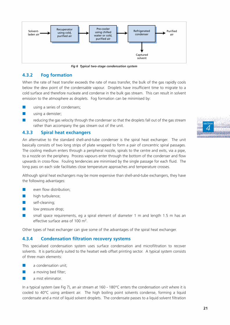
In a two-stage system (see Fig 6), the solvent-laden air stream first enters a recuperator which usesthe cold purified air stream leaving the main condenser as the chilling agent. The air stream is thencooled further in a pre-cooler, eg using chilled water or the cold purified stream, before entering themain refrigerated condenser.
The successive cooling procedure:
■ minimises the refrigerant requirement;
■ condenses most of the high freezing point components, eg water, before freezing occurs;
■ minimises fog formation (see Section 4.3.2).
The size and arrangement of the various condensers should be chosen to optimise thermal efficiencyand minimise equipment cost.
An alternative involves partial condensation at a slightly higher temperature followed by removal ofthe remaining solvent from the air stream by another technique, eg by adsorption.
21
section
4
Fig 6 Typical two-stage condensation system
4.3.2 Fog formation
When the rate of heat transfer exceeds the rate of mass transfer, the bulk of the gas rapidly coolsbelow the dew point of the condensable vapour. Droplets have insufficient time to migrate to acold surface and therefore nucleate and condense in the bulk gas stream. This can result in solventemission to the atmosphere as droplets. Fog formation can be minimised by:
■ using a series of condensers;
■ using a demister;
■ reducing the gas velocity through the condenser so that the droplets fall out of the gas streamrather than accompany the gas stream out of the unit.
4.3.3 Spiral heat exchangers
An alternative to the standard shell-and-tube condenser is the spiral heat exchanger. The unitbasically consists of two long strips of plate wrapped to form a pair of concentric spiral passages.The cooling medium enters through a peripheral nozzle, spirals to the centre and exits, via a pipe,to a nozzle on the periphery. Process vapours enter through the bottom of the condenser and flowupwards in cross-flow. Fouling tendencies are minimised by the single passage for each fluid. Thelong pass on each side facilitates close temperature approaches and temperature crosses.
Although spiral heat exchangers may be more expensive than shell-and-tube exchangers, they havethe following advantages:
■ even flow distribution;
■ high turbulence;
■ self-cleaning;
■ low pressure drop;
■ small space requirements, eg a spiral element of diameter 1 m and length 1.5 m has aneffective surface area of 100 m2.
Other types of heat exchanger can give some of the advantages of the spiral heat exchanger.
4.3.4 Condensation filtration recovery systems
This specialised condensation system uses surface condensation and microfiltration to recoversolvents. It is particularly suited to the heatset web offset printing sector. A typical system consistsof three main elements:
■ a condensation unit;
■ a moving bed filter;
■ a mist eliminator.
In a typical system (see Fig 7), an air stream at 160 - 180°C enters the condensation unit where it iscooled to 40°C using ambient air. The high boiling point solvents condense, forming a liquidcondensate and a mist of liquid solvent droplets. The condensate passes to a liquid solvent filtration
Recuperatorusing cold,purified air
Pre-coolerusing chilled
water or cold,purified air
Refrigeratedcondenser
Capturedsolvent
Solvent-laden air
Purifiedair

22
section
4
unit - where any solid contaminants are removed - and into a solvent/water separator.Approximately 60% of the liquid component is removed in the condensation stage. The recoveredsolvent is passed to the main solvent storage tank for re-use.
The air stream containing the mist of solvent droplets then enters the moving bed filtration unitwhere any solids and solvent droplets are removed. The solvent droplets are recovered via the liquidsolvent filtration unit and the solvent/water separator. A differential static pressure controllerautomatically advances the moving bed filter on a new section of filter, thus maintaining optimumefficiency.
Finally, the air stream passes into the mist eliminator where any remaining aerosol droplets arecollected for recovery in the liquid solvent treatment system. The treated air is discharged to theatmosphere.
Combined condensation and filtration systems are ideally suited for the recovery of high boilingpoint solvents.
Fig 7 Typical condensation filtration recovery system
4.4 CRYOGENIC CONDENSATION
Condensation at extremely low temperatures can be carried out using cryogenic nitrogen. Nitrogenhas the following properties that make it ideal for use as a low temperature refrigerant:
■ low boiling point (-196°C);
■ non-toxic;
■ non-corrosive;
■ non-flammable.
Many industrial processes use nitrogen as an inert blanketing gas to minimise unwanted reactions,prevent fires and reduce product degradation by exposure to air or moisture. The nitrogen gas isproduced by vaporising delivered liquid nitrogen in a heat exchanger. The use of nitrogen to providean inert atmosphere usually means that cooling capacity is ‘freely’ available and no further liquidnitrogen is required for cryogenic condensation.
Cryogenic condensation can take two forms. In the first, the ‘cold’ released when liquid nitrogen isvaporised is used as a coolant, with the solvent vapour condensing on the cold surface of thecondenser. In this case, the maximum solvent concentration of the air stream is set at 25% of lowerexplosive limit. Alternatively, the cryogenic condensation plant is run under an inert atmosphere.This allows the air stream to contain higher concentrations of solvent. The latter system has thefollowing advantages:
■ lower capital and operating costs;
■ reduced plant size.
Air-cooledcondenser
Moving bedfiltration unit
Misteliminator
Capturedsolvent for
filtration andseparation
Capturedsolvent for
filtration andseparation
Capturedsolvent for
filtration andseparation
Solvent-laden air
Purifiedair
Solventdroplets and
air stream
23
section
4
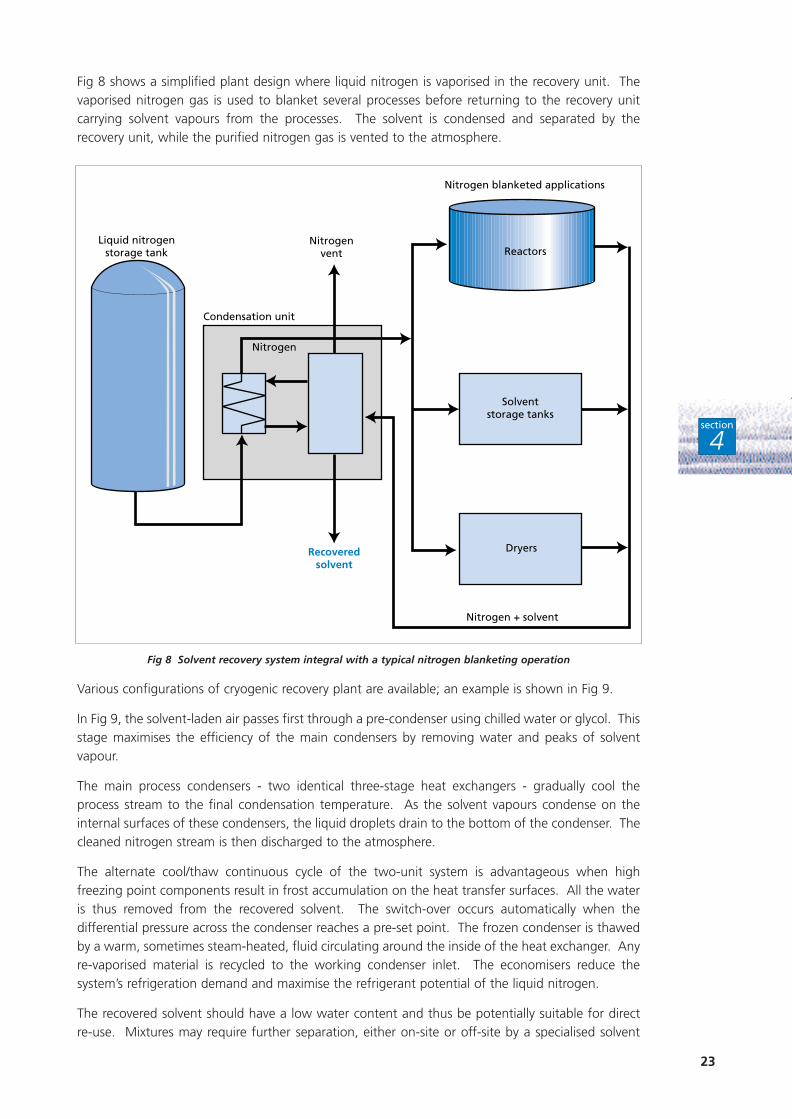
Fig 8 shows a simplified plant design where liquid nitrogen is vaporised in the recovery unit. Thevaporised nitrogen gas is used to blanket several processes before returning to the recovery unitcarrying solvent vapours from the processes. The solvent is condensed and separated by therecovery unit, while the purified nitrogen gas is vented to the atmosphere.
Fig 8 Solvent recovery system integral with a typical nitrogen blanketing operation
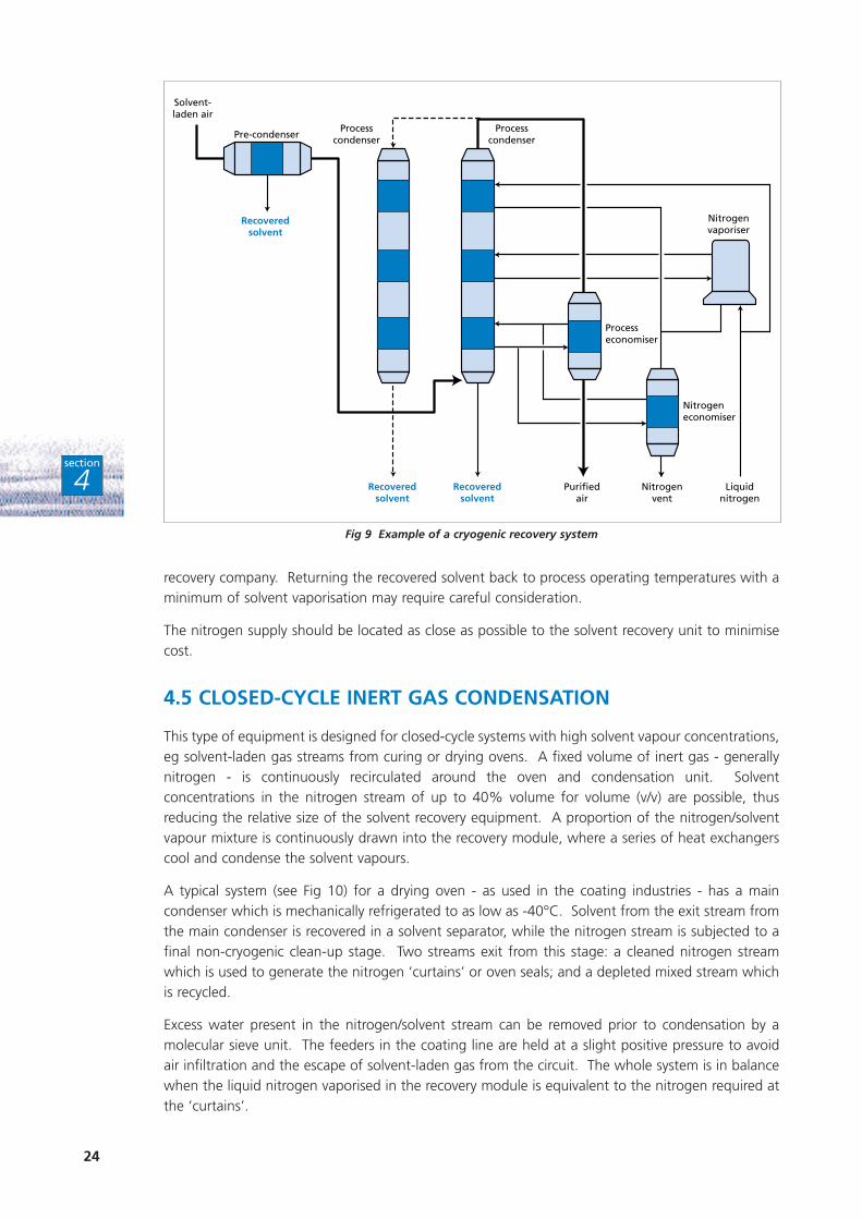
Various configurations of cryogenic recovery plant are available; an example is shown in Fig 9.
In Fig 9, the solvent-laden air passes first through a pre-condenser using chilled water or glycol. Thisstage maximises the efficiency of the main condensers by removing water and peaks of solventvapour.
The main process condensers - two identical three-stage heat exchangers - gradually cool theprocess stream to the final condensation temperature. As the solvent vapours condense on theinternal surfaces of these condensers, the liquid droplets drain to the bottom of the condenser. Thecleaned nitrogen stream is then discharged to the atmosphere.
The alternate cool/thaw continuous cycle of the two-unit system is advantageous when highfreezing point components result in frost accumulation on the heat transfer surfaces. All the wateris thus removed from the recovered solvent. The switch-over occurs automatically when thedifferential pressure across the condenser reaches a pre-set point. The frozen condenser is thawedby a warm, sometimes steam-heated, fluid circulating around the inside of the heat exchanger. Anyre-vaporised material is recycled to the working condenser inlet. The economisers reduce thesystem’s refrigeration demand and maximise the refrigerant potential of the liquid nitrogen.
The recovered solvent should have a low water content and thus be potentially suitable for directre-use. Mixtures may require further separation, either on-site or off-site by a specialised solvent
Liquid nitrogenstorage tank Reactors
Solventstorage tanks
Dryers
Nitrogen blanketed applications
Nitrogenvent
Condensation unit
Nitrogen + solvent
Nitrogen
Recoveredsolvent
24
section
4
recovery company. Returning the recovered solvent back to process operating temperatures with aminimum of solvent vaporisation may require careful consideration.
The nitrogen supply should be located as close as possible to the solvent recovery unit to minimisecost.
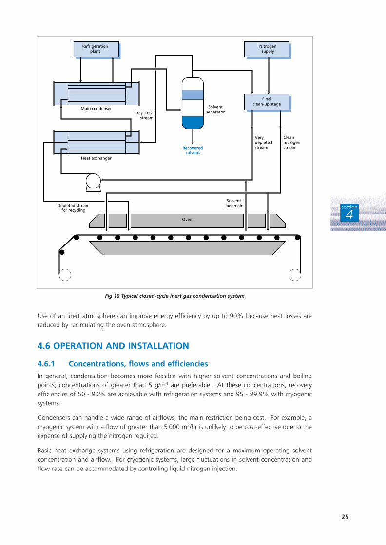
4.5 CLOSED-CYCLE INERT GAS CONDENSATION
This type of equipment is designed for closed-cycle systems with high solvent vapour concentrations,eg solvent-laden gas streams from curing or drying ovens. A fixed volume of inert gas - generallynitrogen - is continuously recirculated around the oven and condensation unit. Solventconcentrations in the nitrogen stream of up to 40% volume for volume (v/v) are possible, thusreducing the relative size of the solvent recovery equipment. A proportion of the nitrogen/solventvapour mixture is continuously drawn into the recovery module, where a series of heat exchangerscool and condense the solvent vapours.
A typical system (see Fig 10) for a drying oven - as used in the coating industries - has a maincondenser which is mechanically refrigerated to as low as -40°C. Solvent from the exit stream fromthe main condenser is recovered in a solvent separator, while the nitrogen stream is subjected to afinal non-cryogenic clean-up stage. Two streams exit from this stage: a cleaned nitrogen streamwhich is used to generate the nitrogen ‘curtains’ or oven seals; and a depleted mixed stream whichis recycled.
Excess water present in the nitrogen/solvent stream can be removed prior to condensation by amolecular sieve unit. The feeders in the coating line are held at a slight positive pressure to avoidair infiltration and the escape of solvent-laden gas from the circuit. The whole system is in balancewhen the liquid nitrogen vaporised in the recovery module is equivalent to the nitrogen required atthe ‘curtains’.
Solvent-laden air
Processcondenser
Processcondenser
Processeconomiser
Nitrogeneconomiser
Nitrogenvaporiser
Purifiedair
Nitrogenvent
Liquidnitrogen
Pre-condenser
Recoveredsolvent
Recoveredsolvent
Recoveredsolvent
Fig 9 Example of a cryogenic recovery system
25
section
4
Use of an inert atmosphere can improve energy efficiency by up to 90% because heat losses arereduced by recirculating the oven atmosphere.
4.6 OPERATION AND INSTALLATION
4.6.1 Concentrations, flows and efficiencies
In general, condensation becomes more feasible with higher solvent concentrations and boilingpoints; concentrations of greater than 5 g/m3 are preferable. At these concentrations, recoveryefficiencies of 50 - 90% are achievable with refrigeration systems and 95 - 99.9% with cryogenicsystems.
Condensers can handle a wide range of airflows, the main restriction being cost. For example, acryogenic system with a flow of greater than 5 000 m3/hr is unlikely to be cost-effective due to theexpense of supplying the nitrogen required.
Basic heat exchange systems using refrigeration are designed for a maximum operating solventconcentration and airflow. For cryogenic systems, large fluctuations in solvent concentration andflow rate can be accommodated by controlling liquid nitrogen injection.
Refrigerationplant
Oven
Nitrogensupply
Finalclean-up stage
Solventseparator
Main condenser
Heat exchanger
Depletedstream
Depleted streamfor recycling
Solvent-laden air
Cleannitrogenstream
VerydepletedstreamRecovered
solvent
Fig 10 Typical closed-cycle inert gas condensation system
26
section
4
4.6.2 Utilities
The utilities required depend on the particular system.
Basic heat exchanger condensers require:
■ a cooling liquid;
■ electricity for fans, pumps and/or refrigeration plant.
Blanketing cryogenic systems require:
■ liquid nitrogen;
■ process coolant (if used);
■ cooling water (if used);
■ electricity for fans and refrigeration plant;
■ steam to heat the fluid used to thaw frozen condensers (if required).
Inert gas cycle systems require:
■ a nitrogen supply for
– the inert atmosphere;
– any emergency purges;
– refrigeration (if used).
■ electricity for fans and refrigerant plant.
An estimated 10 kg/hr of nitrogen cooling in the condensers is needed for each kilowatt of coolingrequired, but this depends on plant design, solvent type, etc. A typical inert gas cycle plant may use1 - 2 tonnes/day.
4.6.3 Control and operation
Basic heat exchange condensers do not generally need dedicated control systems.
Cryogenic systems use standard programmable logic controllers to control nitrogen requirements forcooling. Additionally, on inert gas cycle systems, oxygen analysis is carried out to ensure that an inertatmosphere of less than 5% oxygen is maintained - for safety reasons - in the oven vent stream. Ifthe oxygen content is too high, nitrogen is injected to restore the inert atmosphere. Automaticoperation of the plant should be possible, provided alarms are set as required and routine checks arecarried out by operators during each shift.
4.6.4 Maintenance
Maintenance requirements are generally limited to equipment with moving parts. If mechanicalrefrigeration is used, however, the high pressure compressors may demand significant maintenance.The maintenance of on-site liquid nitrogen tanks is usually the responsibility of the gas supplier.
4.6.5 Ease of retrofitting
Traditional condensation equipment can be readily retrofitted, with the heat exchangers beingpositioned nearby or on top of the relevant piece of equipment.
Cryogenic systems, which are usually only cost-effective on sites that already use nitrogen, may beskid-mounted. Such systems, which may replace any existing nitrogen vaporisers, should be installednear a liquid nitrogen source to minimise the length of cryogenic pipeline. Cryogenic condensationsystems can either be retrofitted to existing plant or integrated into new plant.
In the case of drying ovens, inert gas cycle units are difficult to retrofit onto existing productionplants; they are more suited to new plant.
27
section
4
4.7 COST FACTORS
The following factors influence the cost of a condensation recovery system.
4.7.1 Capital cost
Emission flow rate. This influences the overall size of the system.
Temperature reduction required. The greater the reduction in temperature to achieve the requiredlevel of solvent recovery, the more expensive the equipment. This is especially true for condensationtemperatures well below 0°C because of the greater heat exchange surface required and the needfor specialist equipment for low temperature operation.
Solvent mixtures. Multi-component solvent streams are likely to require more complex separationtechniques.
Solvent solubility. The more soluble the solvent is in water, or other components present in thestream, the more complex the separation technique likely to be required.
4.7.2 Operating costs
Emission flow rate. This dictates utility requirements.
Cooling load. The greater the required cooling load, the more expensive the supply of coolingagent. This is especially true for condensation temperatures well below 0°C, as cryogenic systemscan incur much higher costs unless nitrogen is already used on-site.
Solvent mixtures. More energy-intensive separation techniques are likely to be required.
Solvent solubility. The more soluble the solvent is in water, or other components present in thestream, the more energy-intensive the separation technique likely to be required.
4.8 SUMMARY
■ Coolant/refrigerant condensation is a proven technology. Although widely used, it hastraditionally been used for preliminary recovery prior to, for example, adsorption.Cryogenic systems are less widely used.
■ Condensation techniques use various coolants and refrigerants, as well as cryogenicnitrogen.
■ Concentrated emissions of high vapour pressure solvents are most suitable for recoveryby conventional condensation, while all solvents - irrespective of their vapour pressure -can be recovered using cryogenic condensation.
■ The economic feasibility of condensation depends on the temperature reductionrequired for effective recovery. Condensation temperatures well below 0°C can involvehigher capital and operating costs unless nitrogen is already used on-site.
■ Differential freezing points are likely to occur in the air stream due to the presence ofwater vapour and/or other components. Depending on the condensation temperature,this may lead to frozen material on the heat transfer surface and a subsequent reductionin condensation rate.
■ Cryogenic systems are more likely to be economic where nitrogen is already used on-site.
■ Changing from air to inert gas allows the airflow rate to be decreased and solventconcentrations increased without compromising safety. Changing the airflow in this waywill reduce operating costs, thus making solvent capture and re-use more cost-effective.
28
section
5
A B S O R P T I O N ( S C R U B B I N G ) A N DA S S O C I AT E D T E C H N I Q U E S
5
Absorption is a proven technology, with equipment suppliers having widespread experience of thistype of equipment design and operation. Many such plants for solvent capture and re-use havebeen installed abroad. Most units in the UK have so far only been designed with disposal of theabsorbed solvent in mind.
Absorption is a feasible recovery technique for solvents that are readily soluble in water or a highboiling point organic compound.
5.1 GENERAL PRINCIPLES
Absorption (scrubbing) involves mass transfer in a gas-liquid contacting device between a solventvapour and a scrubbing liquid in which it is readily soluble.
Physical scrubbing, where the solvent does not react with the scrubbing liquid, is preferred forsolvent recovery. Chemical scrubbing, where the solvent reacts with the scrubbing liquid, is usedprimarily for removal of the solvent without recovery. It is not considered here.
As a general rule:
■ the height of the scrubber increases with required absorption efficiency;
■ the cross-sectional area increases with increasing volumetric flow through the scrubber.
The driving force for absorption is the difference between the partial pressure of the solvent in thegas mixture and its vapour pressure in the liquid film in contact with the gas. Absorption does notoccur unless this driving force is positive.
Close contact between the gas and the absorbing liquid is essential for effective absorption. Thiscan be achieved by breaking up the liquid into small droplets or thin films, thus providing a greaterliquid surface area for mass transfer.
For an individual solvent, the required scrubbing liquid circulation rate is determined largely by theairflow rate rather than its concentration in the air stream. The situation is similar in the desorptioncolumn, where the amount of steam required for stripping an individual solvent is controlled by thecirculation rate rather than the solvent concentration. The scrubbing liquid circulation rate thereforetends to be governed by less easily absorbed components and the steam rate by those less easilydesorbed.
As the solvent concentration in a gas stream increases, then so does its partial pressure. Thescrubbing liquid is thus able to absorb more solvent while maintaining performance. At constantairflow, absorption systems therefore have a low sensitivity to variations in solvent concentration.
Higher gas solubilities also provide a greater driving force for more efficient absorption. Since lowertemperatures correspond to lower vapour pressures and higher gas solubilities, absorption isenhanced at reduced temperatures.
Given a suitable choice of scrubbing liquid and plant design, absorption systems are capable of highsolvent capture efficiencies over a wide range of solvents.
29
section
5
5.2 ABSORPTION (SCRUBBING)
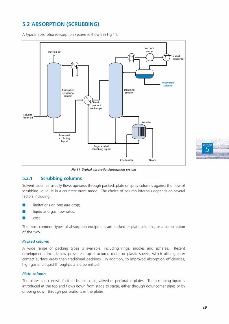
A typical absorption/desorption system is shown in Fig 11.
Fig 11 Typical absorption/desorption system
5.2.1 Scrubbing columns
Solvent-laden air usually flows upwards through packed, plate or spray columns against the flow ofscrubbing liquid, ie in a countercurrent mode. The choice of column internals depends on severalfactors including:
■ limitations on pressure drop;
■ liquid and gas flow rates;
■ cost.
The most common types of absorption equipment are packed or plate columns, or a combinationof the two.
Packed column
A wide range of packing types is available, including rings, saddles and spheres. Recentdevelopments include low pressure drop structured metal or plastic sheets, which offer greatercontact surface areas than traditional packings. In addition, to improved absorption efficiencies,high gas and liquid throughputs are permitted.
Plate column
The plates can consist of either bubble caps, valved or perforated plates. The scrubbing liquid isintroduced at the top and flows down from stage to stage, either through downcomer pipes or bydripping down through perforations in the plates.
Purified air
Feed-product
exchanger
Strippingcolumn
Absorption(scrubbing)
column
Solvent-laden air
Saturatedscrubbing
liquid
Condensate Steam
Reboiler
Recoveredsolvent
Vacuumpump
Guardcondenser
Regeneratedscrubbing liquid
30
section
5
A particular design of spray column uses an impingement baffle plate to achieve gas-liquid contact.The gas stream flows up through perforations in the trays, while the scrubbing liquid is sprayed atthe underside of the trays (through the perforations) and allowed to flow back down the column.Gas-liquid contact and mass transfer are assisted by impingement plates located above eachperforation. The gas flow impinges on these plates, creating additional turbulence and break-up ofliquid films. As solvent vapours partition between the gas and liquid phases, the cooling effectenhances the transfer of vapour to the scrubbing liquid.
This column design results in a low pressure-drop, minimising power requirements for the fan.
5.2.2 Column fouling
Packed columns (unless fluidised) and, to a lesser extent, plate columns, are susceptible to foulingor plugging. This is due to:
■ particulate matter in the inlet air stream;
■ degradation or reaction products in the scrubber liquid stream.
These potential problems can be overcome by installing either a pre-filter to remove incomingparticulate matter, or on-line filters to clean the recirculating liquid. A suitable stabilising agent issometimes required for those organic liquids that have a tendency to degrade, eg ethers.
5.2.3 Scrubbing liquids
Water is the most commonly used scrubbing liquid. However, for water-based absorption, thesolvent vapour must have adequate solubility in water at the operating temperature. For solventvapours with limited water solubility, excessive quantities of water would be required and a lowvolatility organic liquid in which the solvent vapour has good solubility should be used instead.
Scrubbing liquids should satisfy the following criteria for economic, reliable and safe absorption.
Absorption/Desorption properties
Rapid absorption is preferred. Selective absorption may be required for some applications.Desorption temperatures and pressures depend on the type of solvent being scrubbed.
Vapour pressure
Vaporisation of an organic scrubbing liquid leads to additional VOC emissions, which maythemselves require abatement. Liquids with low vapour pressures should therefore be selected. Thiscriterion effectively rules out most potential scrubbing liquids with boiling points of less than 190°Cfor absorption processes operating at ambient temperatures.
Stability
Scrubbing liquids should be long-lasting in the recovery system. They need good thermal andchemical stability to avoid degradation during both absorption and desorption stages. Typicaldesorption temperatures range from 120 - 140°C.
Viscosity
The scrubbing column should be operated at as low a temperature as possible. However, manypotential scrubbing liquids become viscous at low temperatures and do not spread well in packedcolumns. Ideally, the viscosity of the scrubbing liquid should not be significantly greater than thatof water.
Safety/environmental data
Scrubbing liquids with high flash points and ignition temperatures are preferred. The liquid shouldalso have a low toxicity and low odour.
31
section
5
Constant-boiling mixtures
The scrubbing liquid should ideally not form a constant boiling mixture with the solvent beingabsorbed as this creates problems during subsequent processing of the recovered solvent.
Suitable scrubbing liquids include:
■ water;
■ dimethylaniline;
■ amines;
■ higher glycol ethers such as polyethylene glycol and dibutyl ether.
5.3 DESORPTION
Desorption or regeneration of organic scrubbing liquids is usually carried out by steam stripping.This is carried out in a stripping column - usually a packed bed - designed to transfer the solventfrom the liquid mixture back to the gaseous phase. The solvent is then condensed and collected. Itcan either be re-used directly in the process or separated into its component parts, eg by distillation.Steam stripping can be an effective technique for desorption, although water-soluble solvents mayrequire complex separation techniques (eg distillation) for recovery.
In a typical absorption/desorption system (see Fig 11), the saturated scrubbing liquid from thebottom of the absorber is fed via a pre-heater into the desorption column. Here the solvent isstripped out under reduced pressure. The desorption column has steam injected directly into it froma re-boiler. The solvent is condensed in the condenser and collected. A guard condenser is fittedto maximise solvent recovery. Desorbers generally have large liquid flows with comparatively smallvapour flows leading to tall columns with small diameters.
Inert gases, which pass through both condensers, are returned to the absorption column for ventingto atmosphere. The regenerated scrubbing liquid leaves the bottom of the desorber and is recycledback to the absorber via the pre-heater and a final cooler (the absorber operates more efficiently atlower temperatures).
The stripping process is operated at reduced pressure to reduce the temperature required to stripthe solvent from the liquor. This also minimises degradation of the organic scrubbing liquid, thusreducing the amount - and hence the cost - of liquid make-up required.
Degradation can cause particulate material to form within the scrubbing liquid. It may be necessaryfor on-line filters to be fitted to the absorber feed line, or for the liquid distributor to be carefullydesigned, so that any particles can be trapped. Fouling or blockage of the column internals are thuseliminated. The extent of degradation can be assessed by monitoring emissions from the absorber.
Water purged from scrubbing systems should be treated prior to discharge.
5.4 RE-USE OF SOLVENT
For an aqueous scrubbing unregenerated liquid, the most suitable solvent recovery method is likelyto be distillation. However, the scrubbing liquid may be used directly in the manufacturing process,for example, in a polymer coagulation process where solutions of polyurethane indimethylformamide (DMF) are extruded and coagulated in water. DMF vapour, which has a veryhigh affinity for water, is scrubbed out of the extracted air using water in a two-stage (packed andsieve tray) column and the DMF-containing scrubbing liquid is returned directly to the process. Thescrubbing efficiency is greater than 95%.
32
section
5
It may be possible to use a desorber to produce a solvent ready for direct re-use, particularly withsingle solvent streams. If two immiscible solvents are recovered, it may be possible to re-use themafter separation in a phase separator.
If several solvents are captured by the scrubbing liquid or if the water content of the recoveredsolvent is too high, distillation may be required to obtain solvent in an acceptable form for re-use.Distillation can either be carried out on-site by the company concerned or off-site by a specialistsolvent recovery company.
5.5 OPERATION AND INSTALLATION
5.5.1 Flows and efficiencies
The ability to vary three independent parameters to optimise plant performance gives absorptionsystems their versatility. Absorption efficiency can be improved by:
■ designing the absorber for the maximum flow rate;
■ increasing the scrubbing liquid circulation rate;
■ reducing the gas stream temperature.
Desorption of high boiling solvents can be improved by adding more steam, although minimalquantities should be used to ensure that the recovered solvent contains the minimum amount ofwater.
5.5.2 Utilities
The utilities required include:
■ power to drive the fans and pumps;
■ cooling water or chilled water for the condensers;
■ steam at about 120°C for the steam stripper;
■ a vacuum system.
Given good heat exchange between the stripper input and output, the heat requirement forabsorption is likely to be around 30 - 40 kg of steam per 1 000 m3/hr of air. This requirementdepends on:
■ the type and latent heat of the solvent; compounds that are less easily absorbed and requiremore scrubbing liquid also require less steam per unit of scrubbing liquid for desorption;
■ the solvent concentration in the air stream;
■ the amount of reflux required.
In addition to utilities, make-up of the recirculating liquid is required. This depends on:
■ the rate of degradation;
■ any evaporative losses.
5.5.3 Control and operation
A programmable logic controller control system is typically used to control the operation of the plantautomatically. A program is available which can predict the optimum operating parameters -ie circulation and steam requirement - for a given composition of the air stream. This is particularlyuseful where changes in the airflow and/or the solvent concentration are likely to be significant.
Action by plant operators is minimal - perhaps a brief check on the instruments during each shift -provided that automatic shut-down is fitted and alarms set up on the control system, eg for lowliquid flow or loss of vacuum, etc.
33
section
5
5.5.4 Maintenance
Maintenance requirements are likely to be low. They are mainly limited to routine checks on thedesorber vacuum system and equipment with moving parts.
5.5.5 Ease of retrofitting
Provided sufficient space is available, absorption systems can be relatively easily retrofitted to existingplant. Retrofits of existing absorption systems with improved structured packings and/or liquids canalso be carried out to improve the operation of recovery equipment.
5.6 COST FACTORS
The following factors influence the cost of an absorption recovery system.
5.6.1 Capital cost
Emission flow rate. This influences the overall size of the system.
Recovery efficiency required. This influences the height of the scrubbing column.
Solvent type. This dictates the choice of scrubbing liquid.
Solvent mixtures. Multi-component solvent streams are likely to require more complex separationtechniques.
Solvent solubility. The more soluble the solvent is in water, or other components present in thestream, the more complex the separation technique likely to be required.
5.6.2 Operating costs
Emission flow rate. This dictates utility requirements.
Solvent absorption efficiency. This influences the scrubbing liquid recirculation rate, and hence,pumping requirements.
Solvent loading. This dictates the rate of desorption and subsequent utility requirements, eg steam.
Scrubbing liquid degradation. Changes to the scrubbing liquid characteristics and solids build-up(due to high desorption temperature, chemical reactions, impurities in feed, etc) can lead to a highpurge rate of spent liquid. This results in high treatment/disposal costs.
Ease of solvent desorption. High boiling point solvents require higher temperatures for desorption,but condense more readily.
Solvent mixtures. More energy-intensive separation techniques are likely to be required.
Solvent solubility. The more soluble the solvent is in water, or other components present in thestream, the more energy-intensive the separation technique likely to be required.
34
section
5
5.7 SUMMARY
■ Although absorption (scrubbing) has been primarily used in the UK for emissionsabatement, it is a feasible solvent recovery option.
■ For scrubbing to be feasible, the solvent must be readily soluble in either water or a highboiling point organic compound.
■ Absorption can take place in either packed, plate or spray columns.
■ Organic scrubbing liquids are usually regenerated by steam stripping.
■ Aqueous scrubbing liquids can be regenerated by distillation. But it may also be feasibleto use them directly in the process.
■ If the solvent is water-soluble, regeneration with steam may necessitate more complexseparation techniques for solvent recovery.
■ Degradation of the scrubbing liquid is a significant operational factor and may lead tohigh treatment/disposal costs for purged liquid. Degradation is caused by:
– high desorption temperatures;
– chemical reactions;
– impurities in the feed.
■ Provision must be made for the disposal of aqueous and other waste streams purgedfrom the process.
■ Absorption plants themselves require comparatively little floor space. Room is howeverrequired for any effluent treatment plant.
■ Changing from air to inert gas allows the airflow rate to be decreased and solventconcentrations increased without compromising safety. Changing the airflow in this waywill reduce operating costs, thus making solvent capture and re-use more cost-effective.
35
R E C E N T D E V E L O P M E N T S6
section
6
Equipment suppliers are always looking for ways to improve the performance of their existingtechnology and to take account of recent developments. This Section outlines recent developmentsin solvent recovery techniques.
6.1 MEMBRANE PROCESSES
The use of very thin semi-permeable membranes has been developed in the USA over the last fiveto ten years. There are as yet no such installations for solvent capture in the UK. The solvent-ladenair stream is passed over one side of the membrane and a vacuum applied on the other side. Drivenby its partial pressure, the solvent diffuses through the membrane. This results in a moreconcentrated solvent stream on the vacuum side and condensation of most of the solvent-richstream.
Efficient separation requires the membrane to be more permeable to the solvent vapour than to airand/or any other inert gas molecules in the air stream. Efficiency depends on the:
■ selectivity of the membrane;
■ pressure in the air space;
■ pressure in the solvent-rich stream;
■ extent to which solvent vapour has to be stripped from the air stream.
If the concentration of solvent vapour in the air stream is low, a high vacuum is required on thesolvent-rich side of the membrane.
Few commercial applications have resulted from the extensive pilot plant studies carried out. Thisis mainly due to two significant technical problems. Firstly, the transmission fluxes attainablethrough most polymeric films of reasonable thickness are quite low. This means that extremely largemembrane areas are needed to achieve a realistic capacity. Secondly, the selectivity ratios of mostpolymeric materials for solvents of commercial interest is modest. Many of the separations ofinterest are, therefore, not feasible with commercially available polymeric materials.
Due to the system’s high cost, membrane processes are only applicable to low flow rates and solventconcentrations in the range of 1 - 10% v/v.
6.2 PLASTICISER/SOLVENT RECOVERY SYSTEM
Existing technology for the removal of plasticiser and solvent fumes from exhaust gases is beingdeveloped to enable recovery of both plasticiser and solvent.
In the initial stage, the exhaust gas is cooled to below 15°C to maximise the amount of solvent inthe liquid phase. This is followed by an adsorptive recovery stage, which comprises speciallydesigned levels of irrigation and contact medium. A final demisting stage completes the process.Additional recovery and/or treatment stages can be added to ensure that final emission levels areachieved.
Although the process can recover plasticisers efficiently, there are still problems in recovering thesolvent. Some solvent is absorbed by the plasticiser, while plasticiser/solvent separation has proveddifficult. However, the plasticiser/solvent mixture could be re-used, depending on the nature of themanufacturing process, eg in vinyl coating processes, such as wall or floor coverings.
36
section
6
6.3 ADSORBENT REGENERATION
The use of a Brayton-cycle heat pump in an adsorption system reduces the energy cost for adsorbentregeneration by up to 25% compared with conventional systems. The integrated unit employs avacuum pump turbo-compressor to regenerate a saturated adsorption bed. Hot inert gas from thecompressor end of the unit desorbs solvent, which then passes into a chiller. The low temperatureof the chiller is generated at the vacuum end of the unit. With cooling, the solvent condenses andcan be recovered, while the inert carrier gas is ready to be compressed and heated again.
Another development designed to save energy costs during adsorbent regeneration involves theexchange of hot desorbate with water that is later flash-evaporated into low pressure steam. Thissteam passes through a thermo-compressor, raising both its pressure and temperature, and yieldingnew steam for adsorbent regeneration. The system should not only reduce energy costs by up to50%, but should also conserve water for steam generation.
6.4 CONDENSATION SYSTEMS
Most developments in this area involve improvements to heat exchanger equipment. The aim is tomaximise the use of the cooling load, and thus increase energy efficiency, by improving theequipment’s heat exchange parameters. There are ongoing developments in compact heatexchanger technology which offer high performance and low cost heat transfer. See EnergyEfficiency Best Practice programme Good Practice Guide 89, available from the Energy EfficiencyEnquiries Bureau (01235 436747), for further information.
6.5 ABSORPTION SYSTEMS
The main development area is the improvement of column packings. Improved packings have threebenefits:
■ reduced pressure drop through the column (thus reducing fan power requirements);
■ increased separation efficiency which increases the amount of solvent recovered from the airstream and/or reduces the reflux ratio required, minimising column operating costs;
■ increased column capacity which either decreases the column diameter or increases thecapacity of existing columns.
37
W H AT N E X T ?7
section
7
This Guide describes the capabilities of the three main technologies available for on-site solventcapture and re-use. It also indicates ways of improving the economics of each option by examiningfactors such as process airflows and solvent concentrations.
If you are thinking of cost-effectively reducing your company’s VOC emissions you may benefit fromanswering the following questions.
■ Have I investigated all possible ways of minimising solvent use?
■ Could I re-use solvent directly in a process?
■ Could I re-use solvent for some other operation, eg cleaning?
■ Have I investigated waste exchange companies?
■ Have I consulted solvent recovery companies?
■ Can I make solvent recovery more economic by reducing airflows?
■ Can I make solvent recovery more economic by increasing solvent concentrations subject tosafety requirements?
■ Should I change to single solvent operation to make recovery more attractive?
■ Could newer solvent recovery techniques offer improved economics?
If, after reading this Good Practice Guide, you would like help with specific queries regarding solventcapture and re-use, or any environmental problem, please contact the Environmental Helpline on0800 585794. The Helpline can provide you with:
■ general information on solvent minimisation;
■ Environmental Technology Best Practice Programme literature on solvent management, goodhousekeeping measures and, in the future, industrial case studies on solvent minimisation;
■ details of waste exchange and solvent recovery companies.

38
39
appx
A1
A number of directories contain listings of solvent recovery equipment suppliers. These include:
■ ‘Process Engineering Index’ published by Technical Indexes Ltd;
■ ‘Polmark’ Directory (the European Pollution Control and Waste Management Directory)published by Ecotec Research & Consulting Ltd;
■ Kompass published by the CBI;
■ Environment Business Directory published by Information for Industry Ltd;
■ Environment Industry Year book published by The Environment Press Ltd.
The Environmental Helpline (0800 585794) holds details on the above directories.
A list of UK equipment suppliers is given below. The list is not exhaustive and has been compiledfrom information currently available to the Environmental Technology Best Practice Programme. Thelisting of a supplier does not constitute an endorsement by the Programme of either its product orits competence, and neither does the omission of a supplier discriminate against its competence.
ADSORPTION/RECOVERY SUPPLIERS
CONDENSATION/RECOVERY SUPPLIERS
EQUIPMENT SUPPLIERS AND SOLVENTRECOVERY COMPANIES IN THE UK
Appendix 1
AMEG (UK) LtdTel: 01625 614675
Born Environmental LtdTel: 01273 727374
Carbon Link LtdTel: 01942 824240
Chematur LtdTel: 01753 620056
Norit UK LtdTel: 0141 6418841
Rigidon (UK) LtdTel: 01454 294006
Solviron LtdTel: 01787 375004
Sutcliffe Croftshaw LtdTel: 01942 275400
Chemviron Carbon LtdTel: 0161 6285000
CJB Developments LtdTel: 01705 664911
Haden Drysys Env LtdTel: 0121 7654040
Lurgi (UK) LtdTel: 01483 730044
Neu Engineering LtdTel: 0161 4564041
Air Products plcTel: 01270 506000
BOC GasesTel: 01483 244315
Alfa Laval Thermal LtdTel: 0181 5680168
ETE LtdTel: 01928 579283

40
appx
A1
ABSORPTION (SCRUBBING)/RECOVERY SUPPLIERS
The Environmental Helpline (0800 585794) will be able to provide you with informationabout specialist solvent recovery companies and waste exchange organisations.
Begg Cousland and Co LtdTel: 0141 5565288
Born Environmental LtdTel: 01273 727374
Eta Process Plant LtdTel: 01889 576501
Spooner Industries LtdTel: 01943 609505
Sulzer Chemtech DivisionTel: 01252 544311
Lurgi (UK) LtdTel: 01483 730044
Nairb Air LtdTel: 0116 2608187
QVF Process Systems LtdTel: 01785 817211
41
appx
A2
Further information on solvent recovery techniques and technologies can be obtained from thefollowing publications. This is not an exhaustive list.
GENERAL INFORMATION ON SOLVENT RECOVERY TECHNIQUES
Eckert, J S and Schweitzer, P P (eds). Handbook of Separation Techniques for Chemical Engineers. McGraw-Hill. 1979.
Theodore, L and Buonicore, A J (eds). Air Pollution Control Equipment. Prentice-Hall. 1982.
Spivery, J. Recovery of Volatile Organic Compounds from Small Industrial Sources. Environmental Progress. Vol 7, No 1, pp 31 - 41. 1988.
Li, R and Karell, M. Technical, Economic, and Regulatory Evaluation of Tray Dryer Solvent EmissionControl Alternatives. Environmental Progress. Vol 9, No 2, pp 73 - 78. May 1990.
King, M. Technologies for Controlling the Emission of VOCs to the Atmosphere. Trans IChemE Vol 68, Part B, pp 207 - 213. Aug 1990.
McInnes, R., Jelinek, S and Putsche, V. Cutting Toxic Organics. Chemical Engineering, pp 108 - 113. Sept 1990.
Thompson, A. The Removal of VOCs from Gaseous Effluent. Environmental Protection Bulletin. No 10. Jan 1991.
Basta, N and Gilges, K. The Recycling Loop Closes for Solvents. Chemical Engineering, pp 43 - 53. Jun 1991.
Lohman, D. Practical Steps for Reducing VOC Emissions. Industrial Waste Management (nowIndustrial Environmental Management), Vol 3, No 7, pp 10 - 12. Dec 1992.
Smallwood, I. Solvent Recovery Handbook. Hodder and Stoughton. 1993.
Kumar, K S, Pennington, R L and Zmuda, J T. Toxic Air Pollutants. Chemical Engineering, pp 12 - 17. Jun 1993.
Ruddy, E N and Carroll, L A. Select the Best VOC Control Strategy. Chemical Engineering Progress, pp 28 - 35. Jul 1993.
McMullon, J. Weighing up the options for VOC Recovery. Industrial Waste Management (nowIndustrial Environmental Management), Vol 4, No 3, pp 12 - 14. Aug. 1993.
Higgins, T and Thom, J. Solvents - Know Your Options. Chemical Engineering, pp 92 - 100. Mar 1994.
Her Majesty’s Inspectorate of Pollution (HMIP). Pollution Abatement Technology for the Reductionof Solvent Vapour Emissions. Technical Guidance Note (Abatement) A2. HMSO. Mar 1994.
BIBLIOGRAPHYAppendix 2
42
appx
A2
ABSORPTION TECHNIQUES
Stockley, N J. VOC Abatement by Absorption. Environmental Protection Bulletin, No 28, pp 11 - 17. Jan. 1994.
ADSORPTION TECHNIQUES
Sakaguchi, Y. Development of Solvent Recovery Technology using Activated Carbon. Chemical Economy and Engineering Review, Vol 8, No 12, pp 36 - 43. 1976.
Graham, J R and Ramaratnam, M. Recover VOCs using Activated Carbon. Chemical Engineering, pp 6 - 12. Feb 1993.
CONDENSATION TECHNIQUES
Forrester, J S and LeBlanc, J G. A Cool Way to Reduce Emissions. Chemical Engineering, pp 145 - 150. May 1988.
Heil, M D and Jefcoat, I A. Case Study: Assembling Systems to Optimise VOC Recovery. Pollution Prevention Review. Spring 1992.
Rasmuson, A C. Capture Organic Vapours with Liquid Nitrogen. Environmental Engineering World, pp 26 - 29. Jan - Feb 1995.