performance evaluatio n of viscoelas tic dam pers in...
TRANSCRIPT

Internation
© Islamic A
Published o
PERNEAR
R1,2 De
Reca spneaaccocomeffeeartAlseartbehobsConvibrdammotto dnumdiff
1 Research 2 Research 3 Associate CorresponE-mail: sab
nal Journal of A
Azad Universit
online Decemb
RFORMANR-FAULT
Rasoul Sabe
epartment of3 Depa
cords from nepecial propertr-fault earthqompanied wi
mponent perpeect of fault rthquakes causo, due to impthquake energ
havior and plaerved. This nsidering todarations of str
mpers. In thestion or in othedetermine levember of strucferent dampin
Scholar Scholar
e Professor
ndence to: Rasbetahd.r@gmai
Advanced Struc
ty, South Tehr
ber 2011 at (htt
NCE EVAT EARTHQ
et-ahd1, Kols
f Civil Engin
artment of Ci
ar-fault earthqty that show quakes have ith permanenendicular to thrupture. The se the respon
posing of mucgy is absorbstic hinges in
absorption ay’s using eneructures, whese dampers wer words, on el of external
ctural models ng ratios due t
soul Sabet-ahd,il.com
ctural Engineer
an Branch
tp://journals.az
ALUATIOQUAKES
AN
sum Jafarzad
neering, Isla
ivil Engineer
Received
Revised 2
Accepted 2
quakes at clostheir behaviostrong pulse
nt deformatiohe moving suproperties o
nse spectrum ch energy to stbed at first m
height of struof energy
ergy dissipatioere these enwhose energyloading frequl excitation an
have been mo the added v
, Islamic Azad
ring, Vol. 3, N
zad.ac.ir/IJASE
165
ON OF VISUSING N
NALYSIS
deh2 and Mo
mic Azad Un
ring, Univer
d 12 August 2
21 November
29 November
se the distanceor makes theme velocity (p
on of earth. urface of faultf the pulse to show non
tructure durinmaking hingeucture and thecauses large
on systems is nergy dissipaty dissipation muency and to and they act inmodeled in 2viscoelastic da
University, So
No. 2, Pages 165
E)
SCOELASNONLINE
ohammad Al
niversity, Sof
rsity of Tabri
2011
2011
r 2011
e where the wm different frpulsatile wavVelocity pu
t which is the such as velo
n-ordinary beng short perioes instead ofe extension of e relative incurrent due t
tion systems mechanism deactivate these n every earthq2D form in "amper, non-lin
ofian Branch, S
5-177, Decemb
STIC DAMEAR TIME
li Lotfollahi-
ofian Branch
iz, Tabriz, Ir
wave propagatrom other recve) with a ulse occurs i
resultant of docity record ehavior in a pd by these pu
f extension of non-linear benter-story dito reducing th
are passive epends on the dampers therquake. For th"Open Sees" near dynamic
Sofian, Shabea
ber 2011
MPERS INE HISTOR
-Yaghin3
h, Sofian, Ira
ran
tion source is ords. Mostly great period in horizontal directionality in near-fault pulse period. ulses, most of of non-linear ehavior is not isplacements. he earthquake
viscoelastic e velocity of re is no need is purpose, a software for
c analysis has
atar, Iran,
N RY
an

Rasoul Sabet-ahd et al.
/ IJASE: Vol. 3, No. 2, December 2011 166
been done under acceleration of horizontal earthquake and the amount of reduction of displacement response and base shear have been studied. Keywords: passive control, viscoelastic damper, near-fault earthquake, nonlinear dynamic analysis, OpenSees
1. Introduction
Considering the research conducted about land records which are obtained from strong ground
motion in the proximity of fault and also considering the effect of such records on different
structures, greater attention has been given to studies on these records and their effects on
structures during the past two decades. Due to shear waves properties and the cumulative effects
of these waves in front of the path of failure, significant differences can be found between the
characteristics of near-fault earthquakes and those of far-fault earthquakes, among which the
following can be cited in records of near-fault earthquakes the presence of pulse-like motion with
a long period at the beginning of records, larger component perpendicular to the fault than
component parallel to it, accumulation and transfer of energy in short durations, impact-like force
applied to structures existing in the leading failure path, high maximum velocity to maximum
acceleration ratio, and the presence of maximum acceleration and speed and higher displacement
(John, 1995). Northridge (1994) and Kobe (1995): earthquakes caused entire damage or serious
injuries to many modern structures, most of which were attributed to the effects of near-fault
earthquakes, after much research was done. John. F. Hall offered a lengthy report entitled
"Parametric study of steel moment frames’ response to near-fault earthquakes" in December
1995, with an investment of the U.S. Federal Emergency Management Agency (FEMA) (John,
1995). Although the results of this study showed that inelastic stress typically occurs in beams,
the yield may significantly occur in columns too. In addition, the results of relative displacement
values under the intended records for both 6- and 20-story frames suggest that there are higher
displacement-demands of the intended records as near-fault records compared to the limits of
current seismic regulations. At the end, they concluded that the effects of the earthquakes of this
sort (near-fault records) are more than those presented in the regulations. Therefore, to consider
the effects of near-fault records in the seismic regulations, force level in design of regulations for
near-fault earthquakes must be increased (John, 1995). Effects of earthquakes in the proximity of
the fault (especially in the leading direction of failure path) cause severe damages to structures
(especially high-period structures) due to pulse-like motions with a long period. It has also been
empirically observed in Duzce, Chi-Chi, Kobe, Kocaeli and Northridge earthquakes, which led to
regard it as one of the determining factors of urban development so that Rauch & Smolka in their
article (1996) introduced proximity to fault and placement of buildings in failure path of the fault
as two important factors involved in selecting and developing future cities as well as in designing
large cities, after they studied the earthquakes of two large and modern cities of the world (i.e.
Northridge, California (1994) and Kobe, Japan) and the damages caused (Rauch & Smolka,

Performance Evaluation of Viscoelastic Dampers in Near-Fault Earthquakes Using . . .
IJASE: Vol. 3, No. 2, December 2011 / 167
1996). To perform nonlinear dynamic analysis and energy absorbability, Andre & Filiatrault in
1998 analyzed the moment steel frames to examine the actual behavior of the moment steel
frames using a conventional six-story structure. The analysis was conducted on a regular six-
story structure with a moment steel frame which is designed based on the current codes of
regulations. The above structure with two different damping systems affected by the ground
motion, which are representative of near-fault conditions, have been placed under the records
obtained in Los Angeles area with a probability of 10 percent in 50 years; and the behavior of
both systems for energy absorption and energy amortization has been examined by the system
(Andre & Filiatrault, 1998). Studies on the response of structure to the near-fault earthquakes
show that the time-history analysis is better than the response spectrum analysis, because the
specifications of the frequency domain of earthquakes (during the response spectrum) expresses
the process in which there is a relatively uniform distribution of energy during the motion. Thus,
when the energy is concentrated in a few pulses of motion, the phenomenon of resonance is
thought to be provided by the response spectrum should not have enough time for formation
(Somerville & Paul, 2001). Also the damages incurred in the structures as the result of Kobe
(1995, (Mw= 6.7) Northridge (1994) and Izmit (1999) earthquakes have shown that there are
significant differences between the response of structures to the near-and far-fault earthquakes
(Akkar & Gulkan, 2003).
2. Viscoelastic Damper
This damper is designed on the basis of energy dissipation due to shear deformation in solids.
The damper, as Figure 1 shows, consists of the plates between which the polymer materials have
been filled and kinetic energy is wasted with the shear deformation of the polymer layers, so that
viscoelastic material has a polymer molecule structure; and in other words, their molecules are
linked together as chain. As the result of the molecular network above, viscoelastic material
shows a resistance against the deformation – the resistance that is one characteristic of the
material. In fact, stiffness of structural systems will be increased by using this material in the
structure. On the other hand, while deformation is applied to this material, some of the molecular
bonds are broken down and the heat is produced, depending on temperature and the loading
frequency. So, some energy is spent to break the bonds, and is wasted. Damping of these
materials is due to the breakdown of intermolecular bond. After loading over time, the material
recovers their initial strength, which the amount of this recovery depends on the temperature of
the material, stimulant frequency and strain amplitude. In short, one will face an increase in
stiffness and damping in the structural system by using the material above in the structure.
Installation of the dampers should not be limited only to braces, but they can be used with special
arrangements throughout the structure in which shear deformations occur. The experimental
results suggest that the effects of higher modes are reduced and can be ignored using the

Rasoul Sabet-ahd et al.
/ IJASE: Vol. 3, No. 2, December 2011 168
viscoelastic damper in the building. On this basis, there is a good coordination between with the
results of analyses (which were performed according to the first mode) and the experimental
results – the subject which, as one of the strengths of this damper, makes the calculations simple
and easy. Meanwhile, the Kelvin model is used as conventional one to model the dynamic
behavior of the viscoelastic damper, which contains a spring and a linear damper arranged in
parallel. As it is shown in Figure 2, hysteresis graph of this damper is an ellipse, and behaves like
the devices whose properties of damping depend on the speed. To activate them, no level of
external stimulation is needed, and they act as the result of each earthquake, and dissipate the
energy. That is a property that represents the distinction between elastic dampers and friction
dampers, which cannot be activated for the forces less than slip force. In addition, unlike the
viscoelastic dampers, velocity-dependent damping is a linear function of speed, in which the
damping power is 1 for dampers of this kind (Trevor & Kelly, 2001).
Figure 1. Viscoelastic damper
(Trevor & Kelly, 2001) Figure 2. Force-displacement relationship of the
viscoelastic damper (Trevor & Kelly, 2001)
The amount of force in these devices is determined as follows:
uC.KF effD (1)
In viscoelastic dampers, shear-storage modulus and shear-loss modulus are function of the main
vibration frequency of structure, and are used to determine the effective stiffness and damping
(Ramirez et al, 2003).
d
de h
AGK
and
d
de h
AGC
(2)
P
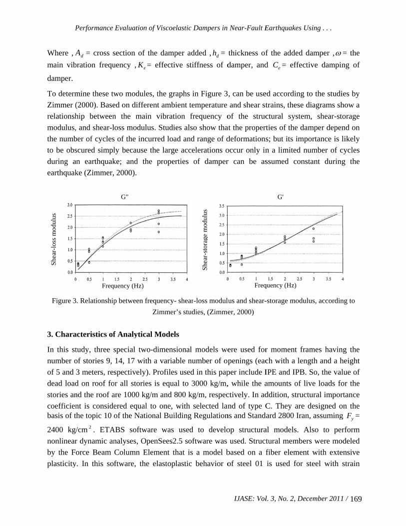
Where , A
main vib
damper.
To determ
Zimmer (
relationsh
modulus,
the numb
to be obs
during a
earthquak
Figure 3
3. Chara
In this st
number o
of 5 and
dead load
stories an
coefficienbasis of t
2400 kg/
nonlinear
by the Fo
plasticity
She
ar-l
oss
mod
ulus
Performance
dA = cross s
bration frequ
mine these tw
(2000). Base
hip between
, and shear-l
ber of cycles
scured simpl
an earthquak
ke (Zimmer,
. Relationship
acteristics of
tudy, three s
of stories 9,
3 meters, re
d on roof fo
nd the roof a
nt is considethe topic 10
/cm 2 . ETA
r dynamic an
orce Beam
y. In this so
Freq
Evaluation of
section of th
uency , eK =
wo modules
ed on differe
n the main
loss modulus
s of the incu
ly because t
ke; and the
2000).
p between fre
f Analytical
special two-
14, 17 with
spectively).
or all stories
are 1000 kg/
ered equal tof the Natio
ABS softwar
nalyses, Ope
Column Ele
ftware, the
quency (Hz)
G"
of Viscoelastic
he damper a
effective st
s, the graphs
ent ambient t
vibration
s. Studies al
urred load an
the large acc
e properties
equency- shea
Zimmer’s stu
l Models
-dimensiona
a variable n
Profiles use
is equal to
m and 800 k
to one, withnal Building
re was used
enSees2.5 so
ement that i
elastoplastic
c Dampers in
added , dh =
tiffness of d
in Figure 3
temperature
frequency o
so show tha
nd range of d
celerations o
of damper
ar-loss modul
udies, (Zimme
l models we
number of op
ed in this pap
3000 kg/m,
kg/m, respec
h selected lang Regulation
d to develo
oftware was
s a model b
c behavior o
She
ar-s
tora
ge m
odul
us
Near-Fault E
IJASE: Vol
thickness of
damper, and
, can be use
and shear st
of the struc
at the propert
deformations
occur only in
r can be as
lus and shear-
er, 2000)
ere used for
penings (eac
per include I
, while the a
ctively. In ad
nd of type Cns and Stand
op structura
used. Struct
based on a f
of steel 01
Freq
Earthquakes
l. 3, No. 2, De
f the added
d eC = effec
ed according
trains, these
ctural syste
rties of the d
s; but its im
n a limited n
ssumed con
-storage modu
r moment fr
ch with a len
IPE and IPB
amounts of
ddition, struc
C. They aredard 2800 Ira
al models. A
tural membe
fiber elemen
is used for
quency (Hz)
G'
Using . . .
ecember 2011
damper , ctive dampin
g to the studi
diagrams sh
em, shear-st
damper depen
mportance is l
number of c
nstant during
ulus, accordin
rames havin
ngth and a h
B. So, the val
live loads fo
ctural impor
e designed oan, assuming
Also to per
ers were mo
nt with exte
steel with
1 / 169
= the
ng of
ies by
how a
torage
nd on
likely
cycles
g the
ng to
ng the
height
lue of
or the
rtance
on the g yF =
rform
odeled
ensive
strain

/ IJAS170
hardening
analyze t
without th
SE: Vol. 3, No
g of 3 perc
the system.
he added vis
o. 2, Decembe
cent; and Ne
For exampl
scoelastic da
Figure 4. Sa
Figure 5. Sa
Rasoul
er 2011
ewmark me
e, the sectio
amper are sh
ample frame w
ample frame w
Sabet-ahd et
thod with ons selected
own in Figu
without added
with a added
t al.
5.0 and
for a 9-stor
ures 4 and 5.
d viscoelastic
viscoelastic d
d 25.0 w
ry structural
damper
damper
was also us
l model with
sed to
h and

Performance Evaluation of Viscoelastic Dampers in Near-Fault Earthquakes Using . . .
IJASE: Vol. 3, No. 2, December 2011 / 171
4. Scaling Using ASCE 7-05
According to ASCE7-05 for analyzing two-dimensional frame, horizontal acceleration of the
ground shall be selected from a real event recorded. When selecting the acceleration,
consideration should be given to their magnitude, the distance of the fault and source
mechanisms. If the appropriate number of recorded history of ground motion is not available,
simulation of the motion should be used. Ground motions must be so scaled that average
acceleration response spectra of selected records with damping ratio of 5% in the interval of
0.2T-1.5T (T is the main period of structure) is not less than the standard design spectrum of
region [9]. Also according to ASCE7-05 for earthquakes with a probability of 2% in 50 years
(MCE), and all active faults known in region, average acceleration response spectra of selected
records must be examined for 1.5 times of the area’s standard design spectrum. To draw standard
design spectrum, it is proposed that values of Ss and S1 be 1.5 and 0.6, respectively; where Ss
and S1, are acceleration response spectrum in the short period and the acceleration response
spectrum in one-second period in a damping ratio of 5%, respectively (American Society of Civil
Engineers, 2005).
4.1. Accelerographs Used
For nonlinear dynamic analysis by using time-history method to evaluate seismic characteristics
of frames, eight accelerations different recorded in type C soils (according to USGC
classification) can be seen in Table 1.
Table 1. Characteristics of earthquake records used in this study
Since the main period in 9-story structures is equal to 1.5 sec, the interval will be between 0.3 to
2.25 seconds. As it is shown in Diagram (6), scale factor of 1.40 is obtained, which is
multiplied in all accelerographs, and is used to analyze the time history. A scale factor of 1.50
can be obtained for 14- and 17-story buildings as well.
PGA(g) Magnitude Station Earthquake NO
0.662 1.7sM Petrolia CapeMendocino(1989) 1
0.653 6.7sM Taiwan Chi-Chi (1999) 2
0.535 3.7sM Duzce Duzce, Turkey (1999) 3
0.454 9.6sM El Centro Array #8 Imperial Valley (1979) 4
0.349 8.7sM Yarimca Kocaeli Turkey (1999) 5
0.322 1.7sM Gilroy Array #2 Loma Prieta (1989) 6
0.59 7.6sMNewhall - Fire Sta Northridge (1980) 7
0.852 4.7sM Tabas Tabas (1978) 8

Rasoul Sabet-ahd et al.
/ IJASE: Vol. 3, No. 2, December 2011 172
Figure 6. Comparison between chart of scaled response spectrum and chart of 1.5 times the standard
design spectrum
5. Determining Damping Ratio Due To the Added Viscoelastic Damper
Given the governing elastic conditions, uniform distribution of damping in the height of the
frame, and given that effective damping, vibration modes, and the way that one can arrange
dampers are specified, damping ratio of added damper in mth mode can be determined from the
following equation for multi-story structural frames (NEHRP, 2001):
n
iim
i
ri
n
iii
mVm
g
W
fCT
1
2
2
1
2
.4
(3)
Where, mT = mth period of the building with the added viscoelastic damper, iW = weight of any
story of the structure, iC = damping factor of the damper, m = mth mode of vibration, if = the
coefficient of damper placement. Considering that the damper was diagonally installed in the frame (as shown in Fig. 5), i.e. cosif , then
miimri )1(- . Vm =damping ratio due to the
added damper in mth mode. Considering Equation (3), ratio of damping resulting from the
desired added damper is obtained by selecting an appropriate shear cross section and shear
thickness for the viscoelastic elements. In other words, the equivalent cross section of brace
element relating to the added damper can be determined using a repeatable process to select the
right size and the main vibration frequency resulting from it. The result is shown in Table 2 for
various models.
0
0.5
1
1.5
2
2.5
0 0.2 0.4 0.6 0.8 1 1.2 1.4 1.6 1.8 2 2.2 2.4 2.6 2.8 3 3.2 3.4 3.6 3.8 4
Period
Sp
ectr
al A
ccele
ratio
n
Average accelerationresponse spectra *Scalefactor
1.5 times of the area’sstandard designspectrum

Performance Evaluation of Viscoelastic Dampers in Near-Fault Earthquakes Using . . .
IJASE: Vol. 3, No. 2, December 2011 / 173
Table 2. Effective stiffness and effective damping of the added dampers
Type of structural
model
ratio of the added damper
( V )
Effective damping Ce (kN.sec/cm)
Period of the main
mode
Equivalent cross section of brace element )( 2cm
Effective stiffness Ke (KN/cm)
Frequency (Hz)
9 floors
5% 15% 25%
16.1 55.96 107.3
1.432 1.3
1.143
1.74 5.89 13.4
62.84 212
482.62
0.7 0.77 0.87
14 floors
5% 15% 25%
29.98 107.77 205.82
1.767 1.556 1.393
3.19 12.08 22.34
114.82 435.19 804.6
0.57 0.64 0.72
17 floors
5% 15% 25%
44.16 164.76 331.68
2 1.76 1.5
3.8 17
37.49
163.96 612
1350.12
0.49 0.57 0.66
As it was expected, the results indicate that the effective stiffness in the combined frames will be
increased with the damping resulting from the addition of elastic damper; and the effective
damping applied has also an upward trend, by increasing the main frequency of frames; and the
damping ratio resulting from the added dampers show an increase.
6. Seismic Response of Frames vs. Damping Ratio
In this study, structural analysis is carried out for three different damping percentages (5, 15, and
25) due to the added damper. A comparison of amounts of displacement and base shear of a 9-
story structure in uncontrolled and controlled modes by inserting viscoelastic damper and 25%
damping due to Tabas earthquake is shown in Figures 7 and 8. The results indicate that
viscoelastic damper can significantly reduce the seismic responses of structures against
earthquakes.
Figure 7. Displacement response of 9-story structure in both uncontrolled and controlled modes with a
viscoelastic damper (added damping of 25%) under Tabas earthquake
-50
-40
-30
-20
-10
0
10
20
30
40
50
60
0 5 10 15 20 25 30 35 40
Time(sec)
Dis
pla
cem
ent(cm
)
Uncontorolled
Controlled (25% damping)

Rasoul Sabet-ahd et al.
/ IJASE: Vol. 3, No. 2, December 2011 174
Figure 8. Base shear response of a 9-story structure in both uncontrolled and controlled modes with a
viscoelastic damper (added damping of 25%) under Tabas earthquake
Also according to ASCE7-05, if the scaled accelerations in time-history analysis are more than
seven in number, the final reflection of structure will be equal to the average values of earthquake
response records. So in the following Figures, the maximum base shear of the stories has been
compared with the maximum roof displacement under eight scaled accelerations in uncontrolled
and controlled modes by added viscoelastic damper and different cases of damping from the
intended structures.
Results of maximum base shear of stories for the intended structures are shown in Figure 9,
indicating that the maximum base shear for all three structures with a damping ratio of 0.25 due
to the added damper can be reduced on average up to 25%; while according to ASCE7-05,
minimum seismic base shear used for designing seismic-resistant systems should not be less thanVV 75.0min . For this purpose, the maximum amount of roof displacement will also be
examined for the damping ratio of up to 0.25 due to the added damper.
Figure 9. Results of maximum base shear of structures
Results of the maximum roof displacement for the intended structures, which are shown in Figure
10, indicate that increasing the damping ratio leads to a constant downward trend for the
maximum story displacement of the roof, and that in case of a damping ratio of 0.25% due to the
-1500
-1000
-500
0
500
1000
1500
0 5 10 15 20 25 30 35 40
Time(sec)
Base S
hear Forc
e(K
N)
Uncontorolled
Controlled (25% damping)
17 Base Shear Force
500
1000
1500
2000
2500
3000
0 5 10 15 20 25Damping Parameter
Bas
e S
hea
r F
orc
e (K
N )
9 Base Shear Force
400
500
600
700
800
900
1000
1100
1200
0 5 10 15 20 25
Damping Parameter
Bas
e S
hea
r F
orc
e (K
N )
14 Base Shear Force
600
800
1000
1200
1400
1600
1800
2000
0 5 10 15 20 25Damping Parameter
Bas
e S
hea
r F
orc
e (K
N )

Performance Evaluation of Viscoelastic Dampers in Near-Fault Earthquakes Using . . .
IJASE: Vol. 3, No. 2, December 2011 / 175
added damper, the maximum roof displacement will be reduced on average up to 56% for all
three structures.
Figure 10. Results of the maximum story displacement of roof
In Figures 11 and 12, structural hysteresis curve in a 9-story structure in uncontrolled and
controlled modes by inserting viscoelastic damper are compared with 25% damping due to Tabas
earthquake. These results show a very high amount of imposed energy, ductility-demands and
displacement-demands of near-fault records. So, to deal with the imposed energy, a structure of
high ductility is required. However, added viscoelastic damper and increasing the damping
resulted from it lead to reducing the condition for entering within the limits of nonlinear behavior
in structural members, and provide dissipation of a part of the energy caused by dampers.
Figure 11. hysteresis curve of a 9-story structure
in uncontrolled mode under Tabas earthquake
Figure 12. hysteresis curve of a 9-story structure
controlled mode with a viscoelastic damper (added
damping of 25%) under Tabas earthquake
7. Conclusions
This research has studied the effect of passive viscoelastic dampers on reducing seismic vibration
of structures. For this purpose, after two-dimensional models of three of 9-, 14- and 17-story
structures were prepared by OpenSees software; the structures with different cases of damping
9 Story
-1500
-1000
-500
0
500
1000
1500
-60 -40 -20 0 20 40 60 80
Displacement (cm)
Ba
se
sh
ea
r (K
N)
Frame
9 Story
-6000
-4000
-2000
0
2000
4000
6000
-25 -20 -15 -10 -5 0 5 10 15 20
Displacement (cm)
Bas
e S
hea
r (K
N)
Frame
Damper
9 Story Displacement
0
5
10
15
20
25
30
35
40
45
0 5 10 15 20 25
Damping Parameter
Dis
pla
cem
ent
(cm
)
14 Story Displacement
0
10
20
30
40
50
60
0 5 10 15 20 25Damping Parameter
Dis
pla
cem
ent
(cm
)
17 Story Displacement
0
10
20
30
40
50
60
70
0 5 10 15 20 25
Damping Parameter
Dis
pla
cem
ent
(cm
)

Rasoul Sabet-ahd et al.
/ IJASE: Vol. 3, No. 2, December 2011 176
due to the added damper were tested by horizontal accelerations of earthquake, to evaluate the
performance of viscoelastic damper. The following were observed from the studies on the
structures:
1- Maximum base shear for all three structures with a damping ratio of 0.25 due to the added
damper is reduced on average up to 25%. Also, according to ASCE-7, minimum seismic base shear used for designing seismic-resistant systems should not be less than V.Vmin 750 .
2- Increasing the damping ratio leads to a constant downward trend for maximum story
displacement of the roof, and in case of a damping ratio of 0.25 due to the added damper, average
of the maximum roof displacement will be reduced on average up to 56% for all three structures.
3- The imposed energy, ductility-demands and displacement-demands of near-fault records are
very high. So, to deal with the imposed energy, a structure of high ductility is required. Added
viscoelastic damper and increasing the damping resulted from it lead to reducing the conditions
for entering within the limits of nonlinear behavior in structural members, and provide dissipation
of a part of the energy caused by dampers.
4- The results indicate the very strong effect of passive viscoelastic dampers in reducing seismic
response of structures. So, these dampers can be used to make the new structures light, or retrofit
existing structures.
References
ASCE7-05, American Society of Civil Engineers (2005), "Minimum Design Loads for Buildings
and other Structures".
BSSC, NEHRP (2001). "Recommended Provisions for Seismic Regulations for New Buildings
and Other Structures, Part2: Commentary”, FEMA- 356, Building Seismic Safety Council,
Washington DC., NY., USA.
Filiatrault, Ander; Tremblay, Robert, (1998), "Seismic Retrofit of Steel Moment Resisting
Frames with Passive Friction Energy Dissipating Systems", NEHREP Conference and Workshop
on Research on the Northridge, California Earthquake January 17, (1994), California
Universities for Research in Earthquake Engineering (CUREe), Richmond, California, pp III-
554---III-561.
Hall, J.F. (1995), "Parameter sudy of the response of moment resisting steel frame building to
near source ground motion", Report NO, EERI 95-08, CA., USA.
Ramirez, O.M., Constantinou, M.C., Whittaker, A.S., Kircher, C.A., Johnson, M.W. and
Chrysostomou, C.Z. (2003), "Validation of the 2000 NEHRP provisions equivalent lateral force

Performance Evaluation of Viscoelastic Dampers in Near-Fault Earthquakes Using . . .
IJASE: Vol. 3, No. 2, December 2011 / 177
and modal analysis procedures for buildings with damping systems", Earthquake Spectra, Vol.
19, No. 4, Pages 981-999.
Smolka, A., Rauch, E. (1996), "The earthquake of northridge 1994 and Kobe 1995-Lessons for
risk assessment and loss prevention with special reference to earthquake insurance", 11th World
Conference on Earthquake Engineering, Pergamon, Elsevier Science Ltd, Oxford, UK., Paper
No. 1847.
Somerville, P. (2001), "Characterizing Near-Fault Ground Motion for the Design and Evaluation
of Bridges", Principal Seismologist, URS Crop. Pasadena CA., USA.
Akkar, S. and Gulkan, P. (2003), "A near-fault design spectrum and its drift limits", 4th
International Conference of Earthquake Engineering and Seismology, p.BS-17.
Kelly, T. (2001), "IN- Structure Damping and Energy Dissipation", S.E. Holmes Consulting
Group, Revision 0, New Zealand.
Zimmer, M. (2000), "Characterization of viscoelastic materials for use in seismic energy
dissipation systems", M.Sc. Thesis, Department of Civil, Structural and Environmental
Engineering, University at Buffalo, State University of New York, Buffalo, NY., USA.