performance enhancements of mbms and voip services in
TRANSCRIPT

��
! 0 �1 �"0 *1 � * � � �� 3 � � 3 � � 3� � � � � � � � � �2��53 ��;
5����4��30�29��������!0�1�"0*1
����������� �����������������������������
������������������� �
������
JYVÄSKYLÄ LICENTIATE THESES IN COMPUTING 13
Kari Aho
Performance Enhancements ofMBMS and VoIP Services
in WCDMA/HSPA Networks
UNIVERSITY OF JYVÄSKYLÄ
JYVÄSKYLÄ 2009

Performance Enhancements ofMBMS and VoIP Services
in WCDMA/HSPA Networks

JYVÄSKYLÄ LICENTIATE THESES IN COMPUTING 13
Kari Aho
Performance Enhancements ofMBMS and VoIP Services
in WCDMA/HSPA Networks
UNIVERSITY OF JYVÄSKYLÄ
JYVÄSKYLÄ 2009
EditorTimo MännikköDepartment of Mathematical Information Technology, University of Jyväskylä
ISBN 978-951-39-3716-4 (PDF)
ISBN 978-951-39-3687-7 (nid.)
ISSN 1795-9713
Copyright © 2009, by University of Jyväskylä
Jyväskylä University Printing House, Jyväskylä 2009
ABSTRACT
Aho, KariPerformance enhancements of MBMS and VoIP services in WCDMA/HSPA net-worksJyväskylä: University of Jyväskylä, 2009, 96 p.(+included articles)(Jyväskylä Licentiate Theses in ComputingISSN 1795-9713; 13)ISBN 978-951-39-3687-7
Finnish summary
The purpose of this thesis is to address the performance of Multimedia Broadcast
Multicast Service (MBMS) and Voice over IP (VoIP) services in Wideband Code Divi-
sion Multiple Access (WCDMA)/High Speed Packet Access (HSPA) networks. MBMSand VoIP services have already gained vast popularity in the fixed networks andthus it is very likely that they will also be key concepts in wireless cellular net-works in the near future. However, from practical perspective, wireless networksets very strict environment for this kind of services. Thus, it is crucial to be ableto evaluate the need of radio resources, possible enhancements and vast num-ber of practical network parameters so that cellular network and these servicesoperate in optimal manner in different situations. This kind of information canbe then used by cellular operators in addition to network and product vendorsin dimensioning and fine-tuning cellular networks. Special attention in this the-sis will be paid on the mobility aspect of both of those services. Studies includethe performance evaluation of MBMS with macro diversity combining with andwithout receive diversity. From the perspective of macro diversity soft and selec-tive combining are evaluated. In addition, concept called Rx-switching is evalu-ated in order to provide some battery saving opportunities for MBMS terminalsemploying multiple receive antennas. On the area of VoIP this thesis addressesthe performance both in uplink and downlink in terms of user velocity, handoverparameters and delays. This kind of performance evaluation is critical as VoIP isvery sensitive to any additional delays and/or packet losses that handover per-formance could potentially cause. This thesis evaluates the performance withhelp of fully dynamic system simulator where user mobility, fading, propagationand radio resource management functionalities are explicitly taken into account.
Keywords: Mobility, Handover, Handover delay, Receive diversity, Transmit di-versity, Macro diversity, Soft combining, Selective combining
978-951-39-3716-4 (PDF), 978-951-39-3687-7 (nid.)13

Author Kari AhoDepartment of Mathematical Information TechnologyUniversity of JyväskyläFinland
Supervisor Professor Tapani RistaniemiDepartment of Mathematical Information TechnologyUniversity of JyväskyläFinland
Examiners Professor Jari IinattiTelecommunication LaboratoryUniversity of OuluFinland
Doctor Seppo HämäläinenNokia Siemens NetworksFinland
ACKNOWLEDGEMENTS
This study is done in co-operation with the University of Jyväskylä, MagisterSolutions Ltd., Nokia Research Center and Nokia Siemens Networks. I wantto express my gratitude to all of my co-workers and colleagues who have pro-vided help, encouragement and support to make this thesis possible, Jussi Äi-jänen, Timo Nihtilä, Tero Henttonen, Jorma Kaikkonen and Karri Ranta-Aho toname just a few. I would also like to give special thanks to my supervising Pro-fessor Tapani Ristaniemi and to my instructor Ph.D. Janne Kurjenniemi for theircontinuous guidance throughout this process.
In addition, I would like to raise up and thank non-profitable foundationswho have provided funding to complete this thesis. That kind of funding isimperative to make academic research possible and to keep finnish know-howamong the top of world. Foundations who have supported the competition ofthis thesis are listed below:
• Nokia säätiö
• Suomen akatemia
• Tekniikan edistämissäätiö
• TeliaSonera Finland Oyj:n tutkimus- ja koulutussäätiö
• Ulla Tuomisen säätiö
Finally, yet importantly, I would like to express my gratitude to my family and allof my friends for their sincere support along the way. I believe that you all knowwho you are and once again thank you from the bottom of my heart.
ACRONYMS
1G First Generation
1Rx One receive antenna
2G Second Generation
2Rx Two receive antennas
3G Third Generation
3GPP Third Generation Partnership Project
AMR-WB Adaptive Multi-Rate - Wideband
AS Active Set
AVI Actual Value Interface
BCH Broadcast Channel
BER Bit Error Rate
BLER Block Error Rate
BM-SC Broadcast-Multicast Service Centre
BS Base Station
BSC Base Station Controller
C/I Carrier to Interference Ratio
CAPEX Capital Expenditure
CBS Cell Broadcast Service
CDMA Code Division Multiple Access
CPICH Common Pilot Channel
CSCF Call Session Control Function
CN Core Network
Codec Coder Decoder
CPCH Uplink Common Packet Channel
CS Circuit Switched
CS Combining Set
CRC Cyclic Redundancy Check
DCCH Dedicated Control Channel
DCH Dedicated Channel
DSCH Dedicated Shared Channel
DSSS Direct Sequence Spread Spectrum
DTCH Dedicated Traffic Channel
DTX Discontinuous Transmission
DL Downlink
Es/No Energy per Symbol to Noise Ratio
Ec/Ior Energy per Chip to Interference Ratio
E-AGCH E-DCH absolute grant channel
E-DCH Enhanced Dedicated Channel
E-DPCCH Enhanced Dedicated Physical Control Channel
E-DPDCH Enhanced Dedicated Physical Data Channel
E-HICH E-DCH HARQ indicator channel
E-RGCH E-DCH relative grant channel
FACH Forward Access Channel
FER Frame Error Rate
FO First Order
GERAN GSM/EDGE radio access network
GGSN Gateway GPRS Support Node
GPRS General Packet Radio Service
GSTN General Switched Telephony Network
GSM Global System for Mobile Communications
HARQ Hybrid Automatic Repeat Request
HLR Home Location Register
HO Handover
HoL Head-of-Line
HS-DSCH High Speed Downlink Shared Channel
HS-SCCH High Speed Common Control Channel
HSDPA High Speed Downlink Packet Access
HSPA High Speed Packet Access
HSS Home Subscriber Server
HSUPA High Speed Uplink Packet Access
I-CSCF Interrogating Call Session Control Function
IETF Internet Engineering Task Force
ILPC Innerloop Power Control
IMS IP Multimedia Subsystem
IP Internet Protocol
IP-MS IP Multicast Service
IR Initialization and Refresh
ITU [International Telecommunication Union
L1 Layer 1
LA Link Adaptation
LTE Long Term Evolution
MAC Medium Access Control
MBMS Multimedia Broadcast Multicast Service
MCCH MBMS Control Channel
MEGACO Media Gateway Control Protocol
MGCF Media Gateway Control Function
MGW Media Gateway
MIMO Multiple Inputs Multiple Outputs
MRC Maximum Ratio Combining
MSCH MBMS Scheduling Channel
MTCH MBMS Traffic Channel
Node B Base Station
NMT Nordic Mobile Telephone
NST Non-Scheduled Transmissions
OLPC Outerloop Power Control
OPEX Operating Expense
P-CSCF Proxy Call Session Control Function
p-t-m point-to-multipoint
p-t-p point-to-point
PC Power control
PCH Paging Channel
PedA Pedestrian A (channel profile)
PDCP Packet Data Convergence Protocol
PDU Protocol Data Unit
PF Proportional Fair
PG Processing Gain
PHY Physical Layer
PS Packet Switched
PSTN Public Switched Telephone Network
QoS Quality of Service
RACH Random Access Channel
Rel’5 Release 5
Rel’6 Release 6
Rel’99 Release 99
RFC Request for Comments
RLC Radio Link Control
RNC Radio Network Controller
RoT Rise over Thermal (RoT)
RR Round Robin
RRM Radio Resource Management
RTCP Real-time Transport Control Protocol
RTP Real-time Transport Protocol
RTT Round-trip time
Rx Receive
S-CCPCH Secondary Common Control Physical Channel
S-CSCF Serving Call Session Control Function
SCS Scheduling Candidate Set
SDP Session Description Protocol
SGSN Serving GPRS Support Node
SID Silence Indicator Frame
SIP Session Initiation Protocol
SINR Signal to Interference and Noise Ratio
SMS Short Message Service
SO Second Order
SRB Signaling Radio Bearer
SSRC Synchronization Source
STTD Space Time Transmit Diversity
TTI Transmission Time Interval
Tx Transmit
UAC User Agent Client
UAS User Agent Server
UE User Equipment
UL Uplink
UTMS Universal Mobile Telecommunications System
UTRAN UMTS Terrestrial Radio Access Network
VehA Vehicular A (channel profile)
VoIP Voice over IP
WCDMA Wideband Code Division Multiple Access
WLAN Wireless Local Area Network
LIST OF FIGURES
FIGURE 1 UMTS Architecture . . . . . . . . . . . . . . . . . . . . . 26FIGURE 2 CDMA Principle . . . . . . . . . . . . . . . . . . . . . . 26FIGURE 3 Example of signal spreading and despreading, [26] . . . . . . 28FIGURE 4 Example of radio signal propagation . . . . . . . . . . . . 28FIGURE 5 Example of constructive (left hand side) and destructive (right
hand side) addition . . . . . . . . . . . . . . . . . . . . . 30FIGURE 6 Example of fast fading process . . . . . . . . . . . . . . . 30FIGURE 7 Principle of Maximum Ratio Combining within the Rake re-
ceiver [26] . . . . . . . . . . . . . . . . . . . . . . . . . 31FIGURE 8 Selective Combining . . . . . . . . . . . . . . . . . . . . 32FIGURE 9 Soft Combining . . . . . . . . . . . . . . . . . . . . . . 33FIGURE 10 Power Control in WCDMA . . . . . . . . . . . . . . . . . 35FIGURE 11 Soft and softer handover procedure . . . . . . . . . . . . . 36FIGURE 12 Offset with HSDPA channels . . . . . . . . . . . . . . . . 38FIGURE 13 HSUPA channels . . . . . . . . . . . . . . . . . . . . . . 39FIGURE 14 Rel’99 retransmissions versus fast retransmissions in HSPA . . 40FIGURE 15 HSPA retransmissions on protocol level . . . . . . . . . . . 40FIGURE 16 HSDPA hard handover . . . . . . . . . . . . . . . . . . . 43FIGURE 17 HSUPA soft handover . . . . . . . . . . . . . . . . . . . 44FIGURE 18 Different ways to deliver data with MBMS . . . . . . . . . . 46FIGURE 19 Basic structure of MBMS multicast service provision [8] . . . 47FIGURE 20 Basic structure of MBMS broadcast service provision [8] . . . 47FIGURE 21 Timeline example of MBMS multicast service provision, [8] . . 49FIGURE 22 MBMS architecture; reference model, [8] . . . . . . . . . . . 50FIGURE 23 Protocol stack for MBMS traffic channel, [10] . . . . . . . . . 51FIGURE 24 Protocol stack for MBMS control channel, [10] . . . . . . . . 52FIGURE 25 Simplified UTRAN MAC architecture with logical MBMS chan-
nels, [10] . . . . . . . . . . . . . . . . . . . . . . . . . . 52FIGURE 26 E-Model rating as a function of Mouth-to-ear delay [ms], [41] . 57FIGURE 27 SIP Architecture . . . . . . . . . . . . . . . . . . . . . . 59FIGURE 28 RTP Frame Structure . . . . . . . . . . . . . . . . . . . . 60FIGURE 29 ROCH state transitions . . . . . . . . . . . . . . . . . . . 62FIGURE 30 Example of IMS system, [27] . . . . . . . . . . . . . . . . 63FIGURE 31 IMS Architecture overview, [22] . . . . . . . . . . . . . . . 63FIGURE 32 Common IMS core overview, [22] . . . . . . . . . . . . . . 64FIGURE 33 Example of VoIP traffic model . . . . . . . . . . . . . . . . 68FIGURE 34 Data flow for HSDPA . . . . . . . . . . . . . . . . . . . . 69FIGURE 35 Data flow for HSUPA . . . . . . . . . . . . . . . . . . . . 70FIGURE 36 Simulation scenario with 21 cells and wrap-around . . . . . . 71FIGURE 37 Simulation scenario with 18 cells and no wrap-around . . . . 71FIGURE 38 VoIP over HSDPA 95 % outage level comparison with differ-
ent velocities . . . . . . . . . . . . . . . . . . . . . . . . 75

FIGURE 39 VoIP over HSDPA 95 % outage level comparison with differ-ent delays . . . . . . . . . . . . . . . . . . . . . . . . . 75
LIST OF TABLES
TABLE 1 Functionality of codes in WCDMA . . . . . . . . . . . 27TABLE 2 Simulation parameters for MBMS reliability analysis . . . 81TABLE 3 Satisfied users with different seed values, BLER < 10 % . . 82TABLE 4 Satisfied users with different seed values, BLER < 1 % . . 83TABLE 5 Required Ec/Ior for 95 % coverage with different seeds . . 84TABLE 6 Statistical confidence for satisfied users, BLER < 10 % . . 84TABLE 7 Statistical confidence for satisfied users, BLER < 1 % . . . 85TABLE 8 Statistical confidence for 95 % coverage level . . . . . . 85TABLE 9 Main simulation parameters for statistical analysis of VoIP
simulations . . . . . . . . . . . . . . . . . . . . . . 85TABLE 10 VoIP over HSDPA outage level with different seeds . . . 86TABLE 11 VoIP over HSDPA 95 % outage level with different seeds . 87TABLE 12 VoIP over HSDPA 95 % outage level with different simu-
lation lengths . . . . . . . . . . . . . . . . . . . . . 87TABLE 13 Statistical confidence for VoIP over HSDPA outage level . 88TABLE 14 Statistical confidence for 95 % VoIP over HSDPA outage
level . . . . . . . . . . . . . . . . . . . . . . . . . . 88TABLE 15 Main simulation parameters for MBMS studies . . . . . 90TABLE 16 Common simulation parameters for VoIP over HSPA sim-
ulations . . . . . . . . . . . . . . . . . . . . . . . . 90TABLE 17 Main simulation parameters for VoIP over HSUPA studies 91TABLE 18 Main simulation parameters for VoIP over HSDPA studies 91
CONTENTS
ABSTRACTACKNOWLEDGEMENTSACRONYMSLIST OF FIGURESLIST OF TABLESCONTENTSLIST OF INCLUDED ARTICLES
1 INTRODUCTION ............................................................................ 191.1 Research problem ..................................................................... 201.2 Related studies ......................................................................... 22
1.2.1 Multimedia Broadcast Multicast Service .......................... 221.2.2 Voice over IP ................................................................. 23
2 WIDEBAND CODE DIVISION MULTIPLE ACCESS .......................... 252.1 Radio Access Network Architecture ........................................... 252.2 Introduction to WCDMA .......................................................... 262.3 Spreading and Despreading ...................................................... 272.4 Multipath Radio Channels......................................................... 27
2.4.1 Attenuation................................................................... 282.5 Receiver................................................................................... 302.6 Macro Diversity........................................................................ 31
2.6.1 Selective Combining ...................................................... 312.6.2 Soft Combining ............................................................. 31
2.7 Receive Diversity...................................................................... 332.8 Power Control .......................................................................... 342.9 Handovers in WCDMA............................................................. 34
2.9.1 Handover categories ...................................................... 352.9.2 Handover types............................................................. 352.9.3 Soft and Softer Handover Procedure................................ 35
2.10 Channels in WCDMA ............................................................... 362.11 High Speed Packet Access ......................................................... 37
2.11.1 High Speed Channels..................................................... 382.11.2 Fast Retransmissions...................................................... 392.11.3 Code multiplexing in HSDPA ......................................... 402.11.4 Scheduling for HSDPA ................................................... 412.11.5 Scheduling for HSUPA ................................................... 422.11.6 Mobility management in HSPA ....................................... 42
3 MULTIMEDIA BROADCAST MULTICAST SERVICE ......................... 453.1 Introduction............................................................................. 453.2 Services ................................................................................... 463.3 Quality of Service ..................................................................... 48
3.4 Architecture ............................................................................. 493.5 Protocols.................................................................................. 513.6 Channels ................................................................................. 513.7 Mobility................................................................................... 53
4 VOICE OVER IP .............................................................................. 554.1 Introduction............................................................................. 554.2 Quality of Service ..................................................................... 564.3 Protocols.................................................................................. 58
4.3.1 Session Initiation Protocol .............................................. 584.3.2 Real-time Transport Protocol .......................................... 594.3.3 Header Compression ..................................................... 61
4.4 IP Multimedia Subsystem.......................................................... 62
5 ACHIEVED RESULTS ...................................................................... 655.1 Research Tool ........................................................................... 65
5.1.1 MBMS Modeling ........................................................... 665.1.2 VoIP Modeling .............................................................. 67
5.2 Simulation Scenario .................................................................. 695.3 Simulation Result Analysis ........................................................ 72
5.3.1 Macro diversity combining impact to the MBMS perfor-mance........................................................................... 72
5.3.2 Impact of Receive Diversity to MBMS performance .......... 725.3.3 MBMS with Transmit Diversity ....................................... 735.3.4 Battery saving opportunities with MBMS 2Rx terminals .... 735.3.5 VoIP over HSUPA performance....................................... 735.3.6 VoIP over HSDPA performance....................................... 74
6 CONCLUSIONS .............................................................................. 76
YHTEENVETO (FINNISH SUMMARY) .................................................... 78
APPENDIX 1 RELIABILITY ANALYSIS ................................................. 801.1 MBMS simulations ................................................................... 801.2 VoIP simulations ...................................................................... 81
APPENDIX 2 SIMULATION PARAMETERS ........................................... 89
REFERENCES ......................................................................................... 92
INCLUDED ARTICLES
LIST OF INCLUDED ARTICLES
PI K. Aho, J. Kurjenniemi, V. Haikola and T. Ristaniemi. System Level Per-formance of Multimedia Broadcast Multicast Services (MBMS) with MacroDiversity. Proceedings of IEEE Wireless Communications and Networking Con-
ference (WCNC), Hong Kong, China, 2007.
PII K. Aho, J. Kurjenniemi, V. Haikola and T. Ristaniemi. Performance en-hancement of Multimedia Broadcast Multicast Services (MBMS) with Re-ceive Diversity. Proceedings of the sixth International Conference on Networking
(ICN), Martinique, France, 2007.
PIII K. Aho, J. Kurjenniemi, V. Haikola, C. Callender and T. Ristaniemi. Mul-timedia Broadcast Multicast Service performance and its enhancementsin WCDMA networks. Wireless Personal Communications, ISSN 0929-6212,2007.
PIV K. Aho, J. Äijänen and T. Ristaniemi. Impact of mobility to the VoIP overHSUPA system level performance. Proceedings of the 67th IEEE Vehicular
Technology Conference (VTC), Singapore, 2008.
PV P. Lunden, J. Äijänen, K. Aho and T. Ristaniemi. Performance of VoIP overHSDPA in mobility scenarios. Proceedings of the 67th IEEE Vehicular Technol-
ogy Conference (VTC), Singapore, 2008.
The author of this thesis was the main author of articles [PI] and [PII] forwhich he took the main responsibility of the simulation work and participatedin the implementation work to add performance indicator statistics to the re-search tool. In article [PIII] the author conducted majority of the simulations,contributed to the result analysis and was the main author of the article. Theauthor of this thesis was responsible of the implementation and modeling work,carrying simulations and writing process in article [PIV]. Finally, in article [PV]
the author participated in simulation scenario planning, analysis and writing ofthe article.

1 INTRODUCTION
Wireless telecommunications industry has undergone many even revolutionarysteps within timespan of just a few decades. From the perspective of commercialwireless cellular technologies, to which this thesis is related to, the beginning ofthis evolution dates back to early 1980’s. During that time so called First Gener-
ation (1G) networks also known as Nordic Mobile Telephone (NMT) networks of-fering voice services were taken into use. First generation networks, based onanalogue technology, were replaced by digital Global System for Mobile Communi-
cations (GSM) networks roughly a decade later. On top of providing voice servicesGSM i.e. Second Generation (2G) systems introduced a new low-cost alternative tocommunicate, Short Message Service (SMS). Along with SMS technology and ca-pability to provide other small bit rate data services GSM has reached huge levelof success by reaching close to 2.7 billion subscribers world wide by the end of2007 [58].
However, growing interest towards more innovative services such as richcalls, mobile-TV and music streaming in the wireless domain acted among thepushing forces to improve the packet data capabilities beyond GSM and its packetdata evolutions. This need was met for the first time in 2001 when the first com-mercial Third Generation (3G) networks utilizing Wideband Code Division Multiple
Access (WCDMA) [26] technique were taken into use. With the highest commer-cially implemented data rate of 384 kbps [26] the deployment of large variety ofnew services requiring higher data rates was now possible. The scope of serviceswas broadened even further when High Speed Packet Access (HSPA) evolutions[27] to 3G networks were introduced. HSPA i.e. 3.5G networks can provide theo-retical peak data rates up to 14.4 Mbps. These higher bit rates companied by thenew range of services have already attracted over 440 million subscribers worldwide by the end of fourth quarter 2008 [58].
Some of those new services consist of sending identical data to vast amountrecipients, for instance mobile-TV can be considered as one of those services.Sending identical information from single source to vast amount of recipients canconsume a lot of radio resources and thus can easily limit the number of userswhich can be served. One innovative solution to improve the performance in
20
previously presented situation is Multimedia Broadcast Multicast Service (MBMS)
[7]. In order to meet the requirements set by various factors such as networkoperators, service providers and subscribers MBMS transmissions aim to deliverservices with as high data rate that is possible by using minimum amount of radioresources.
Even though the increase in the number of subscribers is nowadays fueledby various data services, voice and especially Circuit Switched (CS) voice still re-mains as the main source of revenue for the cellular operators. From operatorperspective having both CS network elements for voice and Packet Switched (PS)
network elements for data services is rather expensive and thus the point of in-terest has moved toward All-IP networks. In other words in the future also voicewould be carried via PS elements. All-IP network would lead inevitability tocost savings as the CS related part of the core network would not be neededanymore thus eliminating/reducing Capital Expenditure (CAPEX) and Operating
Expense (OPEX) related to it. Additionally, by having services like Voice over In-
ternet Protocol (VoIP) i.e. voice carried over PS elements it would enable muchmore simpler implementation of rich call services as the voice and data would bethen carried via same network elements.
MBMS and VoIP are undeniably the key concepts in wireless cellular net-works in the future and thus their performance and possible performance en-hancements require close analysis before actual network implementations. Thisthesis aims to answer to the question of MBMS and VoIP performance in 3G/3.5Gnetworks. In the next section, the research problem of this thesis will elabo-rated further. Studies related to research problem are presented and discussed in1.2. Following sections after related studies deal with basics of WCDMA, HSPA,MBMS, VoIP and finally achieved results accompanied with the presentation ofthe research tool.
1.1 Research problem
When considering user’s mobility in the network, it is crucial to optimize theRadio Resource Management (RRM) functions in the network to prevent major per-formance losses. From the RRM functions, the impact of Handovers (HO) are es-pecially emphasized in this thesis. Moreover, this thesis focuses on evaluatinghow the handover delays, Active Set (AS) sizes and other handover related pa-rameters take effect on the overall system performance in terms of MBMS andVoIP concepts.
Originally, MBMS was designed to use only Downlink (DL) (from the Base
Station (BS) User Equipment (UE)) transmissions to the without any Uplink (UL)
(from UE to BS transmissions) in order to save radio resources. Later there hasbeen discussion to use MBMS principles with HSPA evolutions with some ULcontrol information. However, in order to evaluate the concept from the per-spective of the first 3G devices that do not support HSPA evolutions, this thesis
21
focuses on MBMS over WCDMA. Performance is analyzed with and without dif-ferent performance enhancements considered for MBMS. Thus, apart from opti-mizing the performance in the respect of handover parameters, this study inves-tigates whether MBMS performance can potentially be enhanced with e.g. macrodiversity combining, Receive (Rx) and Transmit (Tx) diversity.
Macro diversity combining means, roughly speaking, that transmissionscoming from different cells/sectors are combined. Macro diversity is the mostlikely option for performance enhancement as the current trends indicate thatMBMS is going to be available through large parts of the network.
Receive diversity, on the another hand, is one of the most efficient diversitytechniques, since in addition to the diversity gain the received combined signalpower is theoretically doubled with two receive antennas when compared to sin-gle antenna reception [45]. However, the size, cost and power resources of UEsomewhat limit the applicability of Rx-diversity and thus transmit diversity i.e.deploying additional Tx-antennas to the base station can be considered as a moreattractive solution.
Taking previously mentioned aspects into account this thesis aims to an-swer to the following questions with the respect of MBMS performance and per-formance enhancements:
• How much MBMS can benefit from macro diversity combining?
• How do the handover parameters effect to the macro diversity combiningschemes?
• What kind of performance enhancement can be achieved with receive andtransmit diversity?
• When network is dimensioned to terminals with one receive antenna (1RX)
and we have terminals with two receive antennas (2Rx), how good power sav-ings opportunities in the UE can we accomplish by switching off additionalreceiver branches when radio conditions allow?
From the perspective of VoIP, the Release 99 (Rel’99) by Third Generation Partnership
Project (3GPP) introduced WCDMA which made it possible for the first time torun VoIP over cellular networks with reasonable quality but however with lowerspectral efficiency than CS voice. The situation changed when HSPA evolutionsto the 3G networks were introduced in Release 5 (Rel’5) and Release 6 (Rel’6) [27].Both high speed evolutions, namely High Speed Uplink Packet Access (HSUPA) andHigh Speed Downlink Packet Access (HSDPA), were conceived in order to achievehigher capacity and coverage for high transmission rates by the means of tech-niques such as Hybrid Automatic Repeat Request (HARQ) and shortened Transmis-
sion Time Interval (TTI) [27]. However, as the previous studies regarding the HSPAevolutions have proved, also delay critical small bit rate services such as VoIPcan benefit from those new features. This thesis aims to deepen the knowledgeof VoIP performance over HSDPA and HSUPA in different mobility related sce-narios. This kind of study is essential as voice services are very sensitive to anyadditional delays and/or packet losses that user mobility can cause.
22
VoIP over HSPA studies in this thesis aim to answer to the following ques-tions:
• What kind of impact user velocity has on the VoIP performance?
• How much VoIP performance is degraded due to delays in the handoverprocedure?
• How well can VoIP users be satisfied when active set size is limited?
• How reliable serving HSDPA cell change is?
• Do Silence Indicator Frames (SID) i.e. comfort noise during silence intervalshave significant impact to the overall performance?
To answer these questions regarding MBMS and VoIP concepts, fully dynamicsystem simulations are carried over. There are at least two factors advocating theusage of system simulations: on the one hand, the complexity of the dynamicnetwork behavior makes it virtually impossible to calculate accurate analyticalresults, and on the other hand, physical network trials would be time consumingand expensive. Thus, fully dynamic system level simulations where user mobil-ity, RRM functionalities and their inter-actions are taken explicitly into accountare essential to the performance evaluations.
1.2 Related studies
3GPP is currently standardizing the MBMS framework and thus studies relatedto the MBMS performance and its enhancements are very crucial. Also as men-tioned before, cellular networks are adopting VoIP and moving toward all-IP net-works which is proved by the fact that e.g. Long Term Evolution (LTE) systems,which are to follow 3G/3.5G networks, support only PS voice [2]. Thus, studiesregarding MBMS and VoIP support the standardization work and in addition aidnetwork vendors and operators to set many practical parameters so that the net-work performance would be optimal in different situations. This section aims topoint out some of the most important studies related to this thesis and elaboratehow this thesis deepens that knowledge.
1.2.1 Multimedia Broadcast Multicast Service
Extensive capacity analysis for MBMS in 3G networks was carried out in [23],where the existence of multiple radio links was considered and evaluated un-der the assumption of soft combining principle. The study showed that withoutcombining roughly 13 % of the Node B power was required for good-enoughcoverage but with soft combining the same number was only 6 %.
23
MBMS was additionally studied in [19], where multi-resolution broadcastsystems such as Multiple Inputs Multiple Outputs (MIMO) were studied in the re-spect of MBMS. Authors showed, for instance, that MIMO with two transmittingand two receiving antennas can double the spectral efficiency in comparison withsingle resolutions systems with corresponding Block Error Rate (BLER) target.
In [43] the trade-offs between resources used for physical layer and resourcesused for application layer with MBMS were considered. The results indicatedthat the balancing of the overheads is necessary in contrast to just focusing on thephysical layer aspects.
MBMS counting mechanisms are addressed for instance in [14] and laterextended to cover also macro diversity concepts in [51]. Counting mechanismsare used to determine the trade-off point when the transmission mode should bechanged from point-to-point (dedicated resources) to point-to-multipoint (sharedresources) mode. Those studies revealed that dedicated and shared channelscould efficiently be used to deliver the MBMS services, selection of which de-pending on the number of users that desire the service and their requirements.
In addition, studies like [17] address MBMS performance analysis on suchissues as longer Transmission Time Interval (TTI), Space Time Transmit Diversity
(STTD) and power and channel allocation with MBMS whereas in the same time[17] indicates that more work on the mobility aspect should be done.
Majority of the existing research is aimed, for instance, to reduce the re-quired Node B’s transmission power for MBMS as it is very limited resource.This thesis deepens the MBMS performance analysis in many respects and thusgives power saving opportunities for Node B as well as for the UE. First of all, dif-ferent combining principles at the UE side are considered and carefully analyzedwith respect to the key parameters which have to be set in practice. Those includee.g. threshold values for adding, dropping and replacing a certain radio link fromthe set of combined radio links as well as timers related to those thresholds. Inaddition, the effects of typical non-idealities like the network non-synchronismand decision delays are considered. Finally, both single and dual receive antennaconfigurations are considered as well as adaptive branch activation/deactivationin the dual antenna case for the sake of UE battery power savings.
1.2.2 Voice over IP
One of the most critical parts of the downlink traffic, when VoIP or real-timetraffic is considered, is how the scheduling works. Tight Quality of Service (QoS)
requirements combined with small packets size with VoIP necessitate to fine tunescheduling from traditional Round Robin (RR) and Proportional Fair (PF) sched-ulers. Scheduling related issues with VoIP are studied closely in e.g. [56] and[44]. In [56] scheduling algorithm for VoIP traffic is presented which is extendedin [44] with dynamic transmission (code and power) resource allocation method.According to results presented in [44] with both of those scheduling related en-hancements VoIP performance can be improved in terms of capacity even 115 %when compared to traditional RR scheduler.

24
Apart from scheduling related issues, impact of mobility and thus servingHigh Speed Downlink Shared Channel (HS-DSCH) change procedure is very crucialregarding services, such as VoIP, which are highly sensitive to excess delay andpacket losses. Mobility aspect in terms of VoIP over HSDPA are addressed e.g.in [55]. According to that study, even though cell change would have a longexecution time, low speed users will not suffer or suffer very slightly from thelost of packets due to handovers. High speed users were, on the other hand,noticed to have interruptions up to 1 second without proper parameter tuningand thus impact the overall VoIP performance.
As coverage is typically limited by the uplink, studies regarding VoIP overHSUPA are also important to evaluate the overall performance of VoIP. The ca-pacity of how many VoIP users can be served per cell in HSUPA networks de-pends on number of parameters. These parameters include such settings as TTIlength, number of retransmissions and relative channel power allocation.
VoIP over HSUPA system level performance with Rel’6 features is evaluatedin [16]. According to the simulation results presented by that paper, VoIP overHSUPA can offer an attractive solution compared to normal CS voice. However,like with HSDPA, careful parameter optimization is needed as for instance bysetting parameter related to combining i.e. active set update procedure can effectthe performance nearly 10 % according to that paper.
HSUPA introduces two new code-multiplexed physical uplink channels:Enhanced Dedicated Physical Data Channel (E-DPDCH) for user data and Enhanced
Dedicated Physical Control Channel (E-DPCCH) for control data. Introduction ofthese channels increases the peak to average power ratio and thus power am-plifier back-off must be increased to fulfill the requirements of adjacent channelleakage ratio. Increasing the back-off results in reduced efficiency and maximumtransmission power. These power issues have impact on the VoIP capacity andtherefore it is crucial to study their impact. This kind of study is presented in[49]. Central finding of that paper is that if more power is allocated to the datachannel, VoIP coverage can be enhanced but total power of UE is very limitedand if less power is reserved for control channel it, for instance, easily leads toincreased TPC error rate.
This thesis aims to deepen the knowledge of VoIP over HSPA performanceby conducting detailed studies where e.g. mobility of users and interactions ofthe radio resource management functionalities are explicitly taken into account.By doing this we are able to point out some aspects that need to be paid spe-cial attention without having costly and time consuming physical network tri-als. This thesis will increase the knowledge on the impact of (hard) HSDPA and(soft) HSUPA handovers, how sensitive VoIP service is to handover/active setupdate delay, velocity and thus find out the conditions where VoIP users are ableto smoothly switch from cell to cell while maintaining good quality of service.

2 WIDEBAND CODE DIVISION MULTIPLE ACCESS
WCDMA is the most commonly adopted radio interface in third generation Uni-
versal Mobile Telecommunications System (UMTS) networks. UMTS and WCDMAare widely described in [26] and in 3GPP specifications [1]. Uplink and downlinkpacket evolutions, HSUPA and HSDPA respectively, to WCDMA are introducedin detail in [26], [27] and [20]. The purpose of this section is to present brieflykey issues related to WCDMA, HSDPA and HSUPA in order to give the readeradequate knowledge to read and review the studies included in this thesis.
2.1 Radio Access Network Architecture
New logical radio access network was needed mainly due to new radio accesstechnology but nevertheless it contains comparable elements to second genera-tion GMS/General Packet Radio Service (GPRS) networks. The UMTS Terrestrial
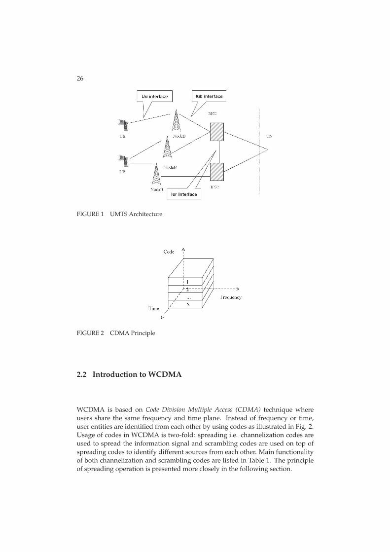
Radio Access Network (UTRAN) architecture, illustrated in Fig. 1, consists of suchlogical elements as Radio Network Controller (RNC) and Node B [26].
UTRAN can contain multiple RNCs which are responsible of controlling theradio resources and Node Bs in its domain. RNCs are connected to each other viaIur interface. When compared to second generation systems RNC correspondsroughly to the GSM Base Station Controller (BSC). Node B, owned by RNC, corre-sponds roughly to the Base Station (BS) in GSM systems. Node B or BS is respon-sible of handling the data flow between Uu i.e. between UE and Node B and Iubi.e. between Node B and RNC interfaces. In this thesis Node B and base stationterminology will both be used to mean solely UMTS network element and notGSM network element unless it is separately specified.
Finally, UTRAN is connected to Core Network (CN) via Iu interface. CN,based on GSM/GPRS systems, is responsible of routing connections between ex-ternal networks and UMTS.
26
FIGURE 1 UMTS Architecture
FIGURE 2 CDMA Principle
2.2 Introduction to WCDMA
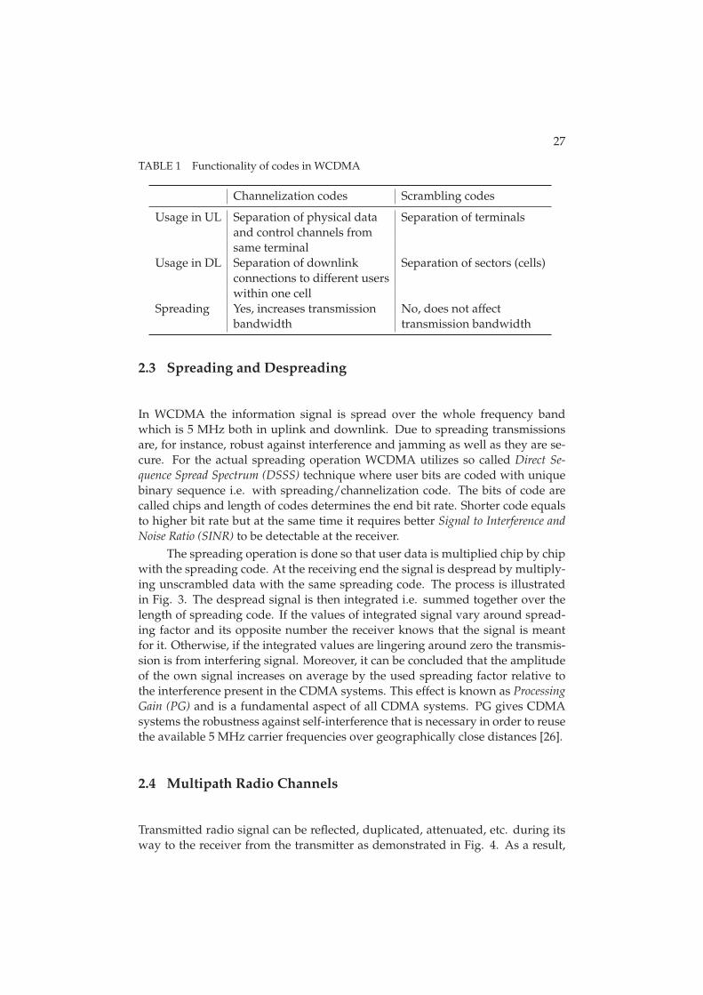
WCDMA is based on Code Division Multiple Access (CDMA) technique whereusers share the same frequency and time plane. Instead of frequency or time,user entities are identified from each other by using codes as illustrated in Fig. 2.Usage of codes in WCDMA is two-fold: spreading i.e. channelization codes areused to spread the information signal and scrambling codes are used on top ofspreading codes to identify different sources from each other. Main functionalityof both channelization and scrambling codes are listed in Table 1. The principleof spreading operation is presented more closely in the following section.
27
TABLE 1 Functionality of codes in WCDMA
Channelization codes Scrambling codes
Usage in UL Separation of physical data Separation of terminalsand control channels fromsame terminal
Usage in DL Separation of downlink Separation of sectors (cells)connections to different userswithin one cell
Spreading Yes, increases transmission No, does not affectbandwidth transmission bandwidth
2.3 Spreading and Despreading
In WCDMA the information signal is spread over the whole frequency bandwhich is 5 MHz both in uplink and downlink. Due to spreading transmissionsare, for instance, robust against interference and jamming as well as they are se-cure. For the actual spreading operation WCDMA utilizes so called Direct Se-
quence Spread Spectrum (DSSS) technique where user bits are coded with uniquebinary sequence i.e. with spreading/channelization code. The bits of code arecalled chips and length of codes determines the end bit rate. Shorter code equalsto higher bit rate but at the same time it requires better Signal to Interference and
Noise Ratio (SINR) to be detectable at the receiver.
The spreading operation is done so that user data is multiplied chip by chipwith the spreading code. At the receiving end the signal is despread by multiply-ing unscrambled data with the same spreading code. The process is illustratedin Fig. 3. The despread signal is then integrated i.e. summed together over thelength of spreading code. If the values of integrated signal vary around spread-ing factor and its opposite number the receiver knows that the signal is meantfor it. Otherwise, if the integrated values are lingering around zero the transmis-sion is from interfering signal. Moreover, it can be concluded that the amplitudeof the own signal increases on average by the used spreading factor relative tothe interference present in the CDMA systems. This effect is known as Processing
Gain (PG) and is a fundamental aspect of all CDMA systems. PG gives CDMAsystems the robustness against self-interference that is necessary in order to reusethe available 5 MHz carrier frequencies over geographically close distances [26].
2.4 Multipath Radio Channels
Transmitted radio signal can be reflected, duplicated, attenuated, etc. during itsway to the receiver from the transmitter as demonstrated in Fig. 4. As a result,

28
FIGURE 3 Example of signal spreading and despreading, [26]
FIGURE 4 Example of radio signal propagation
the receiver actually receives multiple copies of the original signal which differfrom each other by e.g. amplitudes and phases. These copies are referred asso called multipath components of the original signal. By using the informationof these different multipath components the receiver can enhance the quality ofreceived signal and mitigate e.g. the effect of fast fading. Taking advantage frommultipath components is referred as diversity gain. Other forms of diversity andhow they can be taken into account are shortly covered in section 2.6 and coveredwith more details in [28]. However, first forms of signal attenuation i.e. distanceattenuation, slow fading and fast fading are discussed shortly in the followingsection. More detailed study regarding the subject can be seen in [15].
2.4.1 Attenuation
Attenuation can be categorized into three components: distance attenuation, shad-owing i.e. slow fading and fast fading. These components are gone through inthe following subsections.
29
Distance attenuation
Distance attenuation i.e. pathloss means the loss of a signal’s energy as it trav-els over the air from the transmitter to the receiver. The Okumura-Hata pathlossmodel is one of the most widely used for the calculations of coverage. Okumura-Hata model is based on the empirical measurements made by Y. Okumura inTokyo [46], which were then fitted into mathematical model by M. Hata [24]. Ini-tially Okumura-Hata model was applicable only for lower bandwidths but laterit was extended with COST 231 model [21], which made it applicable for band-widths covering also the area of 1500 ≤ f (MHz) ≤ 2000. This combined modelis called COST-Hata model and even though originally those applicable frequen-cies were restricted to below 2000 MHz, it is widely applied for UMTS frequenciesexceeding that. For macro cellular simulation purposes 3GPP has adopted modi-fied Okumura-Hata model which is described in detail in [13]. When consideringa carrier frequency of 2000 MHz and a base station antenna height of 15 meters,the modified model can be described as:
PL(d) = 128.1 + 37.6 × log10(d), (1)
where d is the distance expressed as kilometers. PL(d) shall in no circumstancesbe less than free space loss.
Slow fading
Obstacles such as hills and buildings can come between the UE and Node B andcreate so called shadowing to the received signal. Shadowing is caused by largermovements of a mobile within the propagation environment and usually it ischanging relatively slowly, hence it is often referred as slow fading. The amountof slow fading and more generally signal attenuation depends greatly on the en-vironment, for instance in the country side there can be much better propagationenvironment than in manhattan type of scenario where large number of build-ings are obstructing the signal. This type of fading is generally modeled througha process with a log normal distribution and a correlation distance when simula-tion tools are considered [13] [50].
Fast fading
As mentioned before, when signal is, for example, reflected from a surface of abuilding it can create a multipath component of the transmitted signal. Whenthese multipath signals/components arrive at different times to the receiver theycan cause either a constructive or destructive addition to the arriving plane wavesas shown in Fig. 5. This kind of phenomenon is referred as small scale or fastfading [50].
Multipath components can cause constructive addition to the arriving planewaves if their amplitudes and phases match and destructive addition if theirphases do not match. Result of destructive addition is often signal with a very

30
FIGURE 5 Example of constructive (left hand side) and destructive (right hand side)addition
FIGURE 6 Example of fast fading process
small or zero energy. The rapidity of amplitude variation of received signal is in-fluenced by the speed of the receiver/transmitter and therefore variations mightbe very intensive as an example of fast fading in Fig. 6.
2.5 Receiver
In WCDMA systems the most commonly used receiver is so called Rake receiver.Rake receiver is specially designed to compensate the effects of fading ([47], [48],[52], [53], [26]). Compensating is done by using several ’sub-receivers’ whichare called fingers. Each of those fingers can receive individual multipath compo-nents. Every multipath component arriving at the receiver more than one chiptime (0.26 μs) apart can be distinguished by the Rake receiver. Each component isthen decoded independently and after that combined in order to make the mostuse of the different multipath components and thus reduce the effect of fading.
Combining method used in the Rake receiver is so called Maximum Ratio
Combining (MRC). The Principle of MRC is that the fingers of Rake receiver re-ceive their individual multipath components which are then modified with chan-nel estimate as illustrated in Fig. 7. Channel estimate is acquired from known

31
FIGURE 7 Principle of Maximum Ratio Combining within the Rake receiver [26]
pilot measurements individually for each finger. Finally, those components arecombined by simply summing them together.
2.6 Macro Diversity
Multipath components can be utilized also in such a way that the receiver col-lects, instead of only one source, signals from different cells/sectors and com-bines them in a predefined manner. Sectors from which the signals are used forcombining, are chosen according to UE’s measurements and the group of sec-tors used for combining in a certain moment of time is called a Combining Set
(CS). This kind of method is referred as macro diversity combining. Macro di-versity can be considered as the most likely option for performance enhancementfor services like MBMS as the current trends indicate that MBMS is going to beavailable through large parts of the network. In the following two different meth-ods, introduced in 3GPP Release 6 [10], for macro diversity combining are brieflypresented.
2.6.1 Selective Combining
Receiver with selective combining, Fig. 8, receives and simultaneously decodespackets from different sectors which are in its CS. After the reception and decod-ing the received packet is handled at the Radio Link Control (RLC) layer whereCyclic Redundancy Check (CRC) is performed. Based on the CRC, the first packetwhich is received correctly is chosen. If any of the sources cannot provide error-free packet then the packet is lost.
2.6.2 Soft Combining
The other scheme used to mitigate the erroneous transmissions, illustrated inFig. 9, is called as soft combining. Unlike selective combining, soft combiningis performed on the physical layer. Receiver that uses soft combining collects all

32
FIGURE 8 Selective Combining

33
FIGURE 9 Soft Combining
the packets from different sectors, which are included in the CS. The packets arealigned in time and finally soft values are combined. After the combining is done,the receiver decodes the (combined) packet and checks whether the packet wasreceived correctly or not.
2.7 Receive Diversity
Receive diversity [29] means that the receiver has two or more receive antennasthat are used to collect the multipath components. Even though there is a limitednumber of usable multipath components due to components starting to resembleeach other, multiple receive antennas can receive larger number of usable com-ponents than receiver with one receive antenna. However, an adequate antennaspacing is required. If adequate antenna spacing between multiple antennas isachieved then the received multipath components are sufficiently independentfrom one to another and hence the quality of the received signal can be enhancedwith receive diversity.
In this thesis receive diversity is considered as one of the options to enhanceMBMS performance since in addition to the diversity gain the received combinedsignal power is theoretically doubled with two receive antennas when comparedto single antenna reception. Apart from this study, impact of receive diversity isstudied extensively e.g. in [45]. In addition to ’traditional’ receive diversity also aconcept closely related to the receive diversity called Rx-switching i.e. turning theanother receive antenna off in good channel situations for power saving purposes
34
is studied.
2.8 Power Control
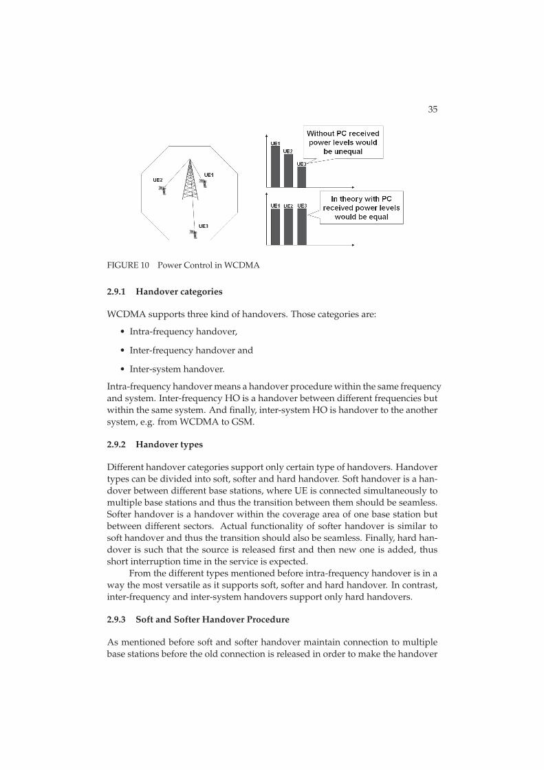
Power control (PC) is one of the key features included in WCDMA [26]. The pur-pose of PC is to ensure that each user receives and transmits just enough energyto prevent blocking of distant users (near-far-effect) and exceeding reasonableinterference levels.
Fig. 10 illustrates how users further away from the base station might beblocked out without power control. In that example, without PC, ’UE3’ might beblocked out due to trying to send with as high power as possible to guaranteehigher signal interference ratio. However, ’UE1’ and ’UE2’ have relatively morepower available as they are closer to the BS and more likely in a better radiochannel condition. However, in this example they would naturally increase theirpower as the interference level is increased because of ’UE3’. Eventually thiscompetitive situation would lead to situation where power limited ’UE3’ wouldbe highly interfered by ’UE1’ and ’UE2’ and thus might be blocked out. Thereforepower control is an essential part of WCDMA.
The actual power control can be divided into open loop power control,which is also referred as slow power control and to closed loop power control,which is referred as fast power control. Open loop power control is used to com-pensate e.g. free-space loss in the beginning of the call when the power levels arenot yet controllable with pilot symbols. When connection has been establishedclosed loop power control steps in. Closed loop power control is used to elim-inate the effect of fast fading and it is applied 1500 times per second, hence thename fast power control.
Moreover, closed loop power control can also be divided into two parts: In-
nerloop Power Control (ILPC) and Outerloop Power Control (OLPC). In ILPC the sig-nal levels are measured and compared to the target value. If the value is higher(resp. lower) than the target then the power is lowered (resp. increased) with acertain step. OLPC, on the other hand, adjusts the target value for ILPC. OLPCcan be used to control e.g. the quality of service but generally the update resolu-tion is lower than 1500 Hz which is used for ILPC.
2.9 Handovers in WCDMA
Generally speaking, handover is an action related to ongoing call which switchesone radio channel to another in order to guarantee the defined quality of bearerservice and continuity of an established call. The purpose of this section is topresent what kind of handover categories and types there are in addition tosoft(er) handover procedure which is essential part of the WCDMA [26].
35
FIGURE 10 Power Control in WCDMA
2.9.1 Handover categories
WCDMA supports three kind of handovers. Those categories are:
• Intra-frequency handover,
• Inter-frequency handover and
• Inter-system handover.
Intra-frequency handover means a handover procedure within the same frequencyand system. Inter-frequency HO is a handover between different frequencies butwithin the same system. And finally, inter-system HO is handover to the anothersystem, e.g. from WCDMA to GSM.
2.9.2 Handover types
Different handover categories support only certain type of handovers. Handovertypes can be divided into soft, softer and hard handover. Soft handover is a han-dover between different base stations, where UE is connected simultaneously tomultiple base stations and thus the transition between them should be seamless.Softer handover is a handover within the coverage area of one base station butbetween different sectors. Actual functionality of softer handover is similar tosoft handover and thus the transition should also be seamless. Finally, hard han-dover is such that the source is released first and then new one is added, thusshort interruption time in the service is expected.
From the different types mentioned before intra-frequency handover is in away the most versatile as it supports soft, softer and hard handover. In contrast,inter-frequency and inter-system handovers support only hard handovers.
2.9.3 Soft and Softer Handover Procedure
As mentioned before soft and softer handover maintain connection to multiplebase stations before the old connection is released in order to make the handover

36
FIGURE 11 Soft and softer handover procedure
as seamless as possible. This procedure is characterized by number of parametersand the purpose of this section is to cover them and their purpose briefly.
Example of soft(er) handover procedure is illustrated in Fig. 11. If we startto follow the x-axis of that figure which represents time in this example, at first UEis connected to only ’BS1’ i.e. UE’s active (or combining) set contains only ’BS1’.A bit later signal from ’BS2’ reaches the ’Threshold_1’ which is more commonlyknown as ’Add window’. ’Add window’ represents a value of how much worse anew signal can be compared to the best one in the current active set in order to beadded into the set. Adding link to combining set can be done only if maximumnumber of links is not full yet (defined with parameter). Moreover, a new linkis added to the active set only if the difference between the best and the new isstill at least as good after the ’Triggering time_1’ (’add timer’) is expired. Timer isstarted when the signal first reaches the desired level.
The opposite for adding is dropping the link from the active set. Link isto be dropped if the ’drop window’ parameter illustrated as ’Threshold_2’ in thefigure is met. Similarly to adding also signal which is to be dropped needs tofulfill the drop condition after the corresponding drop timer is expired.
Finally, parameter called as ’replace window’ represents a value for howmuch better a new signal has to be compared to the poorest one in the currentactive set in order to replace its place. Replace event takes place only if active setis full as otherwise ’add’ event would be applied.
2.10 Channels in WCDMA
In WCDMA there exists two types of transport channels: Dedicated Channels (DCHs)
and common channels. The main difference between them is that the resourcesare shared between users when common channels are used whereas a DCH re-source is reserved for a single user only that is continuous and independent fromthe DCHs of other UEs. The main transport channels used for packet data trans-missions in WCDMA are called as DCH and Forward Access Channel (FACH) [26].
37
In WCDMA systems there exists only one dedicated channel which is knownas DCH. DCH is used to carry user data and all higher layer control informa-tion, such as handover commands. DCH is characterized by features such as fastpower control and soft handover. Fast data rate change on a frame-by-frame basisis supported in the uplink. However, in the downlink data rate variation is takencare of either with a rate-matching operation or with Discontinuous Transmission
(DTX) instead of varying spreading factor frame-by-frame basis. If downlink ratematching is used then data bits are either repeated to increase the rate or punc-tured to decrease the rate. With DTX the transmission is off during a certain partof the slot.
FACH is a shared downlink transport channel that can be used to carrypacket data in addition to mandatory control information. FACH is used, forinstance, to indicate that random access message has been received by BTS. Dueto the reason that FACH carries vital control information, FACH has to have sucha low bit rate that it can be received by all the UEs in the cell area. However, therecan be more than one FACH in a cell which makes it possible to have higher bitrates for the other FACHs. The FACH does not support fast power control or softhandover.
In addition to FACH there are five different common channels in WCDMA:the Broadcast Channel (BCH), Paging Channel (PCH), Random Access Channel (RACH),Uplink Common Packet Channel (CPCH) and Dedicated Shared Channel (DSCH). Fromthe common channels most notable in terms of data transmissions is FACH asDSCH was optional feature that was seldom implemented by the operators andlater replaced in practice with HSDPA. Thus, 3GPP decided to take DSCH awayfrom Release 5 specifications onwards. Also, CPCH has been taken out of thespecifications from Rel’5 onwards as it was not implemented in any of the prac-tical networks [26].
2.11 High Speed Packet Access
High Speed Packet Access (HSPA) consists of improved packet data capabilities inboth uplink and downlink for WCDMA networks. Downlink evolution is calledas High Speed Downlink Packet Access (HSDPA) and it was introduced in Release5. Release 6 introduced uplink counterpart of the evolution called as High Speed
Uplink Packet Access (HSUPA).HSPA was originally conceived to achieve higher capacities and coverage
for non-real time traffic with high transmission rate requirements. These require-ments were met by the means of innovative techniques such as fast Layer 1 (L1)
retransmissions referred as Hybrid Automatic Repeat Request (HARQ), Node B con-trolled scheduling and shortened Transmission Time Interval (TTI). However, asthe previous capacity and mobility studies regarding the HSPA evolution haveproved (see e.g. [56], [44], [55] and [16]), also delay critical small bit rate services,such as VoIP, can benefit from those new features.
38
FIGURE 12 Offset with HSDPA channels
The following sections deal with those new features and properties of HSPAwhich are the most essential in terms of VoIP. The reason why some of the key fea-tures of HSPA are neglected in the following sections is that VoIP does not requirehigh peak data rates that are achieved in HSPA e.g. through Link Adaptation (LA)
and higher order modulation and coding. More details of HSPA can be acquiredfrom e.g. [27] and [20].
2.11.1 High Speed Channels
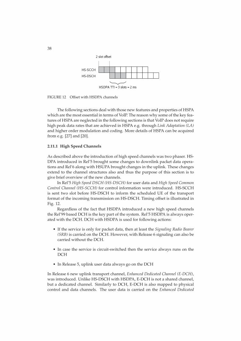
As described above the introduction of high speed channels was two phaser. HS-DPA introduced in Rel’5 brought some changes to downlink packet data opera-tions and Rel’6 along with HSUPA brought changes in the uplink. These changesextend to the channel structures also and thus the purpose of this section is togive brief overview of the new channels.
In Rel’5 High Speed DSCH (HS-DSCH) for user data and High Speed Common
Control Channel (HS-SCCH) for control information were introduced. HS-SCCHis sent two slot before HS-DSCH to inform the scheduled UE of the transportformat of the incoming transmission on HS-DSCH. Timing offset is illustrated inFig. 12.
Regardless of the fact that HSDPA introduced a new high speed channelsthe Rel’99 based DCH is the key part of the system. Rel’5 HSDPA is always oper-ated with the DCH. DCH with HSDPA is used for following actions:
• If the service is only for packet data, then at least the Signaling Radio Bearer
(SRB) is carried on the DCH. However, with Release 6 signaling can also becarried without the DCH.
• In case the service is circuit-switched then the service always runs on theDCH
• In Release 5, uplink user data always go on the DCH
In Release 6 new uplink transport channel, Enhanced Dedicated Channel (E-DCH),was introduced. Unlike HS-DSCH with HSDPA, E-DCH is not a shared channel,but a dedicated channel. Similarly to DCH, E-DCH is also mapped to physicalcontrol and data channels. The user data is carried on the Enhanced Dedicated

39
FIGURE 13 HSUPA channels
Physical Data Channel (E-DPDCH) while new control information is on the En-
hanced Dedicated Physical Control Channel (E-DPCCH).Much like HSDPA, HSUPA is not a standalone feature but requires Rel’99
DCH. From the Rel’99 DCH, the dedicated physical control channel is unchangedand the need for the DPDCH depends on possible uplink services mapped to theDCH. DPCCH is used e.g. for fast power control.
In addition to transport channel new channels for scheduling control werealso introduced with HSUPA: E-DCH absolute grant channel (E-AGCH), E-DCH
relative grant channel (E-RGCH) and E-DCH HARQ indicator channel (E-HICH). E-AGCH is used to inform about absolute scheduling value i.e. an absolute powerlevel that the UE should adopt. E-AGCH can in principle allow transition be-tween minimum and maximum data rates as well as any smaller data rate changein between the two extremes [26]. Absolute grant channel is sent only from serv-ing cell. E-RGCH is a relative scheduling channel which transmits step up/downcommands. Non-serving cell can transmit only hold/down commands in orderto reduce and keep the interference levels on reasonable levels. New channel forretransmission control, E-HICH, carries the information in the downlink direc-tion on whether a particular base station has received the uplink packet correctlyor not. HSUPA channels are illustrated in Fig. 13.
2.11.2 Fast Retransmissions
HSPA introduced changes to the basic WCDMA architecture in terms of transfer-ring functionality from RNC to the Node B. Fast retransmissions are one of thenew improvements placed in the Node B level whereas in Rel’99 retransmissionswere possible to employ only from RNC, see Fig. 14. Fast retransmissions arepossible to be initiated/requested from Node B as the scheduling responsibilityis one of the key functionalities that has been moved to Node B. Scheduling willbe addressed more detailed later in this thesis.
The benefit from fast retransmissions comes from layer 1 signaling, depicted

40
FIGURE 14 Rel’99 retransmissions versus fast retransmissions in HSPA
FIGURE 15 HSPA retransmissions on protocol level
in Fig. 15, which indicates the need of retransmission much faster leading tomuch lower round trip time than with Rel’99 retransmission procedure. Layer 1retransmissions (HARQ) are operated in practice so that at the receiving end thedecoder does not get rid of the received symbols if the transmission (i.e. CRCcheck) fails but combines them with retransmissions. There are two ways thatretransmissions can operate: with identical retransmissions which are commonlyreferred as soft/chase combining or with non-identical retransmissions which isknown also as incremental redundancy combining [27].
2.11.3 Code multiplexing in HSDPA
As referred earlier, HSDPA was designed primarily to provide higher data ratedelivery to end-users. When introducing relatively low bit rate services, suchas VoIP over HSDPA, downlink capacity could be wasted by serving only one
41
(VoIP) user at a time. For situations like that HSDPA introduces so called code-multiplexing to allow more than one user being scheduled in a single TTI [27].According to Rel-6 specifications, each simultaneously scheduled HSDPA userrequires HS-SCCH channel. Thus, total amount of required power for HS-SCCHincreases when users are code multiplexed and moreover it also limits the num-ber of code-multiplexed users.
2.11.4 Scheduling for HSDPA
In terms of delay critical services, such as VoIP, scheduling, i.e. when users areallowed to transmit or to be transmitted to, is definitely one of the most importantaspects in terms of keeping the delay in reasonable limits. Thus, this and thefollowing section cover briefly how scheduling is handled in the downlink anduplink directions. This section will deal with downlink scheduling and firstlycouple of the most common scheduling schemes are presented and after that theyare followed with potential VoIP enhancements.
Round Robin (RR) is one of the most simplest scheduling algorithms and itis often used as a benchmarking reference for more advanced scheduling algo-rithms. With RR users are served in sequential order i.e. all users are handledwithout priority. Positive sides with RR are that it is very easy to implement andeach user gets served equally. On the another hand, channel conditions are nottaken into account and thus valuable radio resources might be wasted and thusnetwork throughput might suffer.
When compared to RR Max C/I in the other extreme of the scheduling alter-natives if channel conditions and the scheduling fairness between users are takenas indicators. Whereas RR schedules users in sequential order Max C/I sched-ules users purely according their channel conditions. The user that has the bestchannel conditions in given time gets scheduled. This maximizes the throughputfrom the network perspective but the user fairness can suffer significantly.
Proportional Fair (PF) is a compromise-based scheduling algorithm basedupon maintaining a balance between two competing interests: maximizing net-work throughput by serving users in good channel conditions but at the sametime allowing all users at least a minimal level of service. In practice this is doneby assigning each users a scheduling priority that is inversely proportional toits anticipated resource consumption. High resource consumption leads to lowpriority and vice versa. However, priority is shifted with the factor which takesinto account the occasions the user has been scheduled previously. In general thepriority metric for users is calculated in a following manner:
p = d/r. (2)
In Eq. 2 the instantaneous data rate, d, is obtained by consulting the link adapta-tion algorithm and average throughput of the user, r, is defined as follows:
r =
{(1 − a)× rold + a × d, if the user is served(1 − a)× rold, otherwise.
(3)

42
Here a is so called forgetting factor. Hence, a−1 equals to the equivalent averagingperiod in a number of TTIs for the exponential smoothing filter [26].
Normal proportional fair scheduler has some disadvantages when delaycritical traffic is considered as it does not take delay of the queued packets intoaccount as such. Improved scheduling and resource allocation algorithm for VoIPhas been studied closely in [56] and [44]. Those papers present enhancement topure PF algorithm by introducing so called Scheduling Candidate Set (SCS) fromwhich the actual scheduling algorithm, for instance PF, selects users from. SCS isupdated in each TTI so that it includes users who have certain number of VoIPpackets buffered in the Node B, whose Head-of-Line (HoL) packet delay is largeenough or who have pending retransmissions in their HARQ manager.
2.11.5 Scheduling for HSUPA
Scheduling for uplink is necessary to keep the interference levels reasonable 1 andthus improving the probability to get transmissions through. Similarly to HS-DPA, also HSUPA scheduling has been moved from RNC to Node B allowing tomake scheduling decisions with minimum latency. Regarding HSUPA two differ-ent scheduling schemes are defined: scheduled transmissions and Non-Scheduled
Transmissions (NST) [27].Scheduled transmissions are, as the name implies, controlled by Node B.
Node B and UEs will signal at each time instant of how much resources UEswould need and then Node B assigns maximum transmit rate for each user sothat the interference level experienced at the BS will not exceed certain reasonablelevel. However, the downside of scheduled transmissions with this approach isthat when, for instance, VoIP is considered satisfactory minimum bit rate mightnot be achieved and in addition each request requires time and resource consum-ing signaling.
NSTs are controlled by RNC which defines a minimum data rate at whichthe UE can transmit without any previous request. This reduces signaling over-head and consequently processing delays. To meet the tight delay requirementsset for VoIP application, RNC controlled NTS of E-DCH is the most suitablechoice for VoIP traffic as it enables the UE to transmit the VoIP packets as soon asthey arrive to the physical layer.
2.11.6 Mobility management in HSPA
Handovers are one of the most crucial parts of the successful user experience asthey can cause, for instance, additional delays or even disruption times to thetransmissions. In terms of HSPA the handover procedure is somewhat alteredwhen compared to Rel’99 WCDMA [27]. With HSDPA, the user can be connectedto one serving HSDPA Node B at the time leading to hard handover when the
1 measured generally through Rise over Thermal (RoT) i.e. noise rise which indicates the ratiobetween the total power received from all of the UEs at the base station and the thermalnoise [54]
43
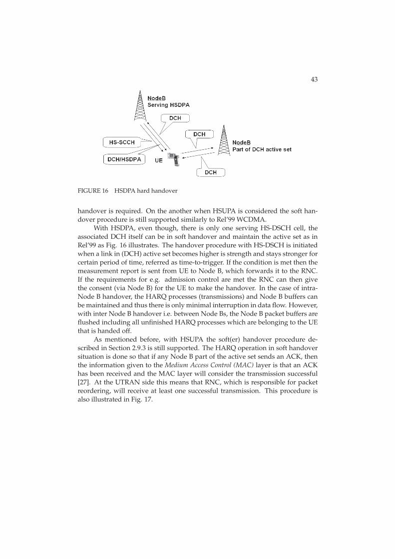
FIGURE 16 HSDPA hard handover
handover is required. On the another when HSUPA is considered the soft han-dover procedure is still supported similarly to Rel’99 WCDMA.
With HSDPA, even though, there is only one serving HS-DSCH cell, theassociated DCH itself can be in soft handover and maintain the active set as inRel’99 as Fig. 16 illustrates. The handover procedure with HS-DSCH is initiatedwhen a link in (DCH) active set becomes higher is strength and stays stronger forcertain period of time, referred as time-to-trigger. If the condition is met then themeasurement report is sent from UE to Node B, which forwards it to the RNC.If the requirements for e.g. admission control are met the RNC can then givethe consent (via Node B) for the UE to make the handover. In the case of intra-Node B handover, the HARQ processes (transmissions) and Node B buffers canbe maintained and thus there is only minimal interruption in data flow. However,with inter Node B handover i.e. between Node Bs, the Node B packet buffers areflushed including all unfinished HARQ processes which are belonging to the UEthat is handed off.
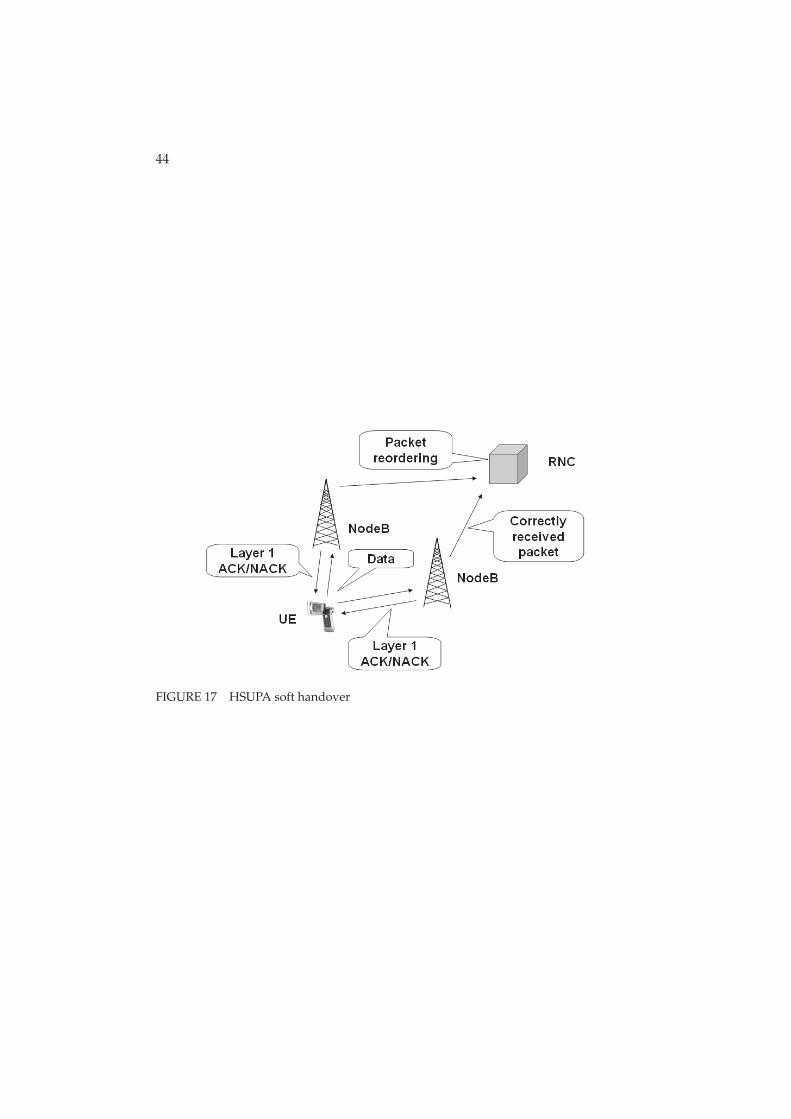
As mentioned before, with HSUPA the soft(er) handover procedure de-scribed in Section 2.9.3 is still supported. The HARQ operation in soft handoversituation is done so that if any Node B part of the active set sends an ACK, thenthe information given to the Medium Access Control (MAC) layer is that an ACKhas been received and the MAC layer will consider the transmission successful[27]. At the UTRAN side this means that RNC, which is responsible for packetreordering, will receive at least one successful transmission. This procedure isalso illustrated in Fig. 17.
44
FIGURE 17 HSUPA soft handover
3 MULTIMEDIA BROADCAST MULTICAST SERVICE
Multimedia Broadcast Multicast Service allows different forms of multimediacontent to be delivered efficiently by using either broadcast or multicast mode.The term broadcast refers to the ability to deliver content to all users who haveenabled a specific broadcast service and find themselves in a broadcast area. Mul-ticast, on the other hand, refers to services that are delivered solely to users whohave joined a particular multicast group. Multicast group can be, for example, anumber of users that are interested in a certain kind of content, such as sports.In contrast to the existing solutions for one-to-many data delivery in mobile net-works MBMS makes more efficient use of network resources and capacity. In thefollowing sections MBMS is presented from the technical specifications point ofview in order to provide the reader with basic understanding of MBMS.
3.1 Introduction
Up until recent times broadcast and multicast transmissions in 3G networks havebeen dealt with by using either the Cell Broadcast Service (CBS) which is definedin [3] and [4] or the IP Multicast Service (IP-MS) which is described in [5] and[6]. However, those methods contain some problems. With CBS it is not possibleto send anything other than message-based services with low bit rates. Situa-tion with IP-MS is not that much better as there is no capability to use sharedradio or core network resources for traffic intended for multiple recipients. With-out shared resources, the overall use of radio resources easily exceeds the wan-ted/reasonable level. In order to compensate these defects there has been re-search on the area of delivering information to a large number of users. Thisresearch has brought up a new group transmission method called: MultimediaBroadcast Multicast Services (MBMS), [7].
The aim of MBMS transmissions is to send identical information from sin-gle source to vast amount of recipients with high data rates by using minimumamount of radio resources. MBMS efficiency is based on the possibility to use ei-
46
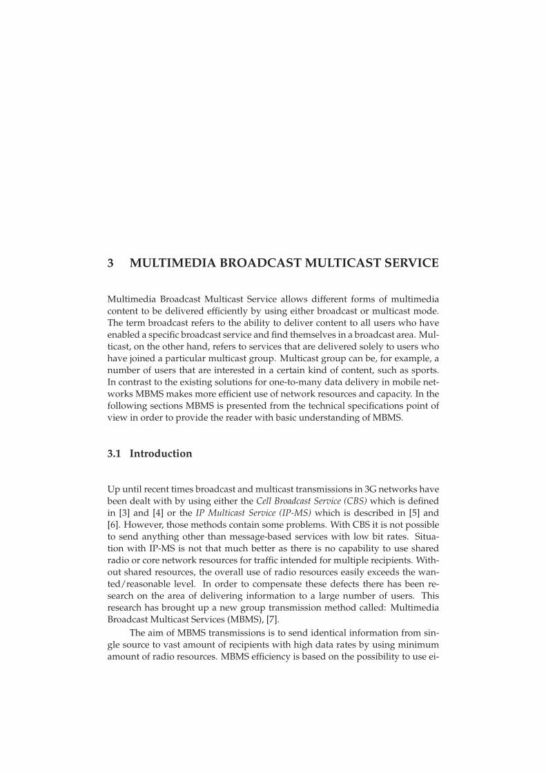
FIGURE 18 Different ways to deliver data with MBMS
ther shared or dedicated resources i.e. point-to-multipoint (p-t-m) or point-to-point
(p-t-p) transmission modes for the content delivery as shown in Fig. 18. Point-to-point transmissions are used to transfer both MBMS specific control/user planeinformation as well as dedicated control/user plane information between net-work and single UE. Point-to-multipoint transmissions are used to transfer MBMSspecific control/user plane information between the network and several UEs. Ingeneral p-t-p connections are appropriate to be used when only a few users in acell want to use MBMS services and p-to-m connections are suitable when a largenumber of users want to view the identical content. From the network point ofview there exists so called counting procedures which allow network to figureout whether services should be configured as p-t-p or p-t-m in a particular area.Thus, UE might have to deal with dynamic changes between dedicated and com-mon resources when crossing the cell edge.
As MBMS can use bandwidth more efficiently and is also capable of deliv-ering multimedia content with different modes (multicast/broadcast), also thescope of the possible services is much larger than with CBS or IP-MS. Serviceslike mobile-TV and delivering real-time sport results can be considered examplesof such services.
3.2 Services
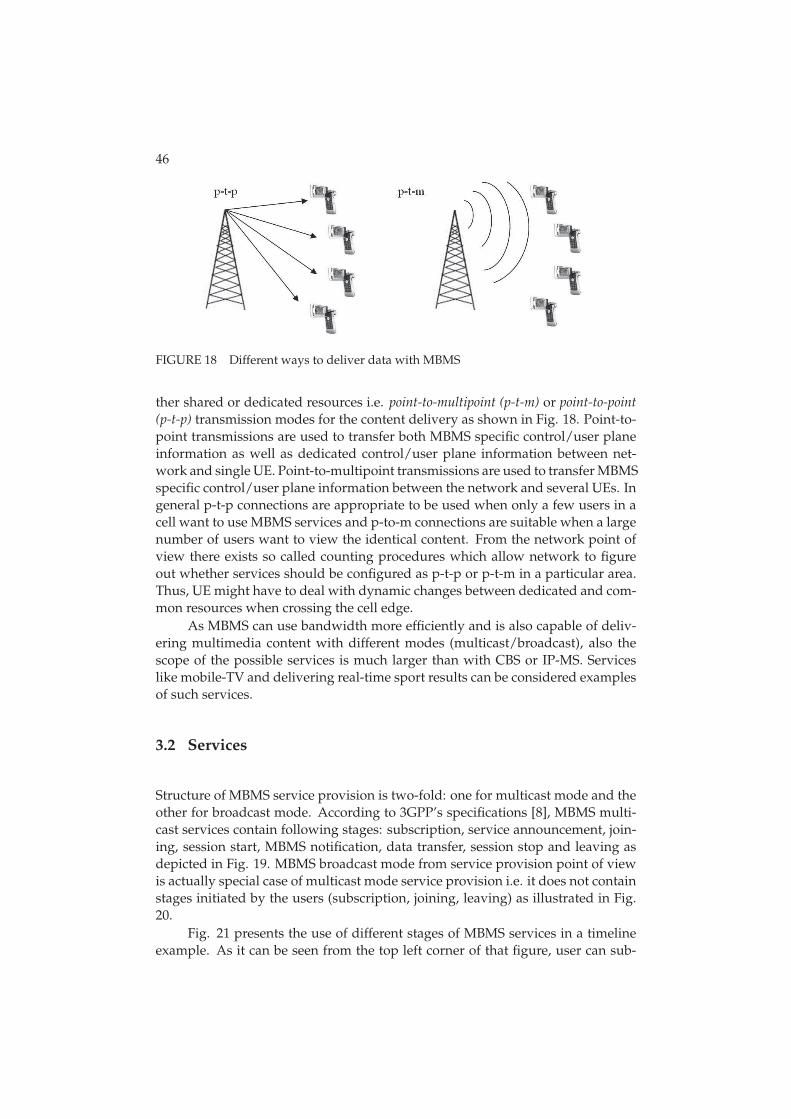
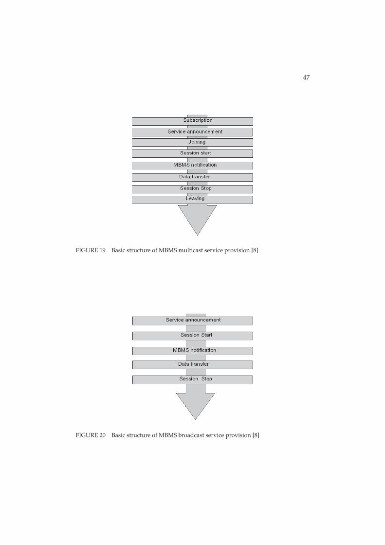
Structure of MBMS service provision is two-fold: one for multicast mode and theother for broadcast mode. According to 3GPP’s specifications [8], MBMS multi-cast services contain following stages: subscription, service announcement, join-ing, session start, MBMS notification, data transfer, session stop and leaving asdepicted in Fig. 19. MBMS broadcast mode from service provision point of viewis actually special case of multicast mode service provision i.e. it does not containstages initiated by the users (subscription, joining, leaving) as illustrated in Fig.20.
Fig. 21 presents the use of different stages of MBMS services in a timelineexample. As it can be seen from the top left corner of that figure, user can sub-
47
FIGURE 19 Basic structure of MBMS multicast service provision [8]
FIGURE 20 Basic structure of MBMS broadcast service provision [8]
48
scribe service at any time. By subscribing a certain service(s) user establishes therelationship to the service provider by making agreement of receiving service(s)offered by the operator/service provider. After the subscription has been made,according to [8], service provider starts the service announcement which is usedto distribute information about the service to the users. Information about theservice contains the parameters required for service activation (e.g. IP multicastaddress(es)) and possibly other service related parameters such as service starttime. Morever, as Fig. 21 shows, after service announcement has been made bythe service provider, users can join to the service group at any point they likewhich means that the MBMS service stages can overlap.
After subscribing, service announcement and joining phases session start isthe point when RNC receives a request from the CN to start the session. Sessionstart is independent of the actions made by users and therefore users can joinin to the multicast group even during of a MBMS session. After session startrequest has been received MBMS notification procedure is required to be usedto inform member of multicast group about forthcoming (and potentially aboutongoing) MBMS multicast data transfer. This procedure must be transmitted sothat every UE in MBMS service area can receive it as it contains vital informationsuch as MBMS radio bearer setup information. Notification procedure shouldalso allow terminals to minimize their power consumption, meaning that UEswith an activated MBMS service should not listen to it constantly, but on regularintervals.
After the data has been transferred and the RNC receives information fromthe CN that there will be no more data to send for some period of time session,stop phase is carried out. During session stop phase radio access bearers arereleased.
Even though session has been stopped users are not obligated to leave thegroup because another session might start after a small period of time. However,if service provider makes a service stop announcement then users must leave theMBMS multicast group. More detailed information about MBMS services can befound in [8] and [10].
3.3 Quality of Service
The purpose of this section is to discuss a few of the quality of service relatedaspects when MBMS is considered. Some of the discussed matters are set by3GPP as requirements for MBMS, [9].
As mentioned earlier in this thesis, MBMS data transfer is specified to beunidirectional traffic and to be more precise downlink only. This is specified in[9] along with the fact that QoS attributes shall be the same for MBMS multi-cast and broadcast modes. One of the most important QoS aspects is caused bythe lack of uplink traffic as it discloses such things as feedback and individual re-transmissions. Thus, the reception of MBMS content is not guaranteed. However,

49
FIGURE 21 Timeline example of MBMS multicast service provision, [8]
reliability of MBMS transmissions is improved e.g. by using periodic repetitionsof MBMS content from the service provider so that the number of satisfied userscan be maintained at a reasonable level. Repetitions are not precluded by the lackof uplink traffic because the service provider can transmit them without feedbackfrom the UE. Periodical repetitions are done on RLC level with identical RLC se-quence numbers and Protocol Data Unit (PDU) content. As data loss is requiredto be minimal also during cell change, there has been made effort to achieve thise.g. by using soft and selective combining. Moreover, also antenna diversity tech-niques can be considered as an option to improve the reliability. Thus, this thesisaims to investigate the applicability of those improvements.
3.4 Architecture
In MBMS architecture existing packet switched domain entities such as Gateway
GPRS Support Node (GGSN), Serving GPRS Support Node (SGSN), UTRAN and UEare included/enhanced to be able to provide the MBMS bearer services. 3GPP’sreference model for MBMS architecture is described in [8] and illustrated in Fig.22. MBMS related entities and their functionalities are discussed briefly in thefollowing.
Starting from the left side of the Fig. 22, the first entity involved in MBMSoperation is UE which is operated by the end user. User will use UE to activateand deactivate MBMS services and no other explicit user requests are required.
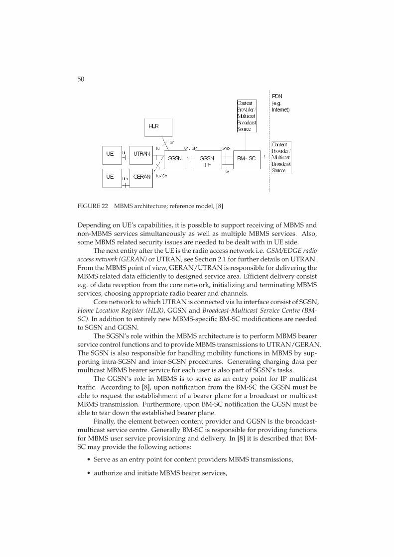
50
FIGURE 22 MBMS architecture; reference model, [8]
Depending on UE’s capabilities, it is possible to support receiving of MBMS andnon-MBMS services simultaneously as well as multiple MBMS services. Also,some MBMS related security issues are needed to be dealt with in UE side.
The next entity after the UE is the radio access network i.e. GSM/EDGE radio
access network (GERAN) or UTRAN, see Section 2.1 for further details on UTRAN.From the MBMS point of view, GERAN/UTRAN is responsible for delivering theMBMS related data efficiently to designed service area. Efficient delivery consiste.g. of data reception from the core network, initializing and terminating MBMSservices, choosing appropriate radio bearer and channels.
Core network to which UTRAN is connected via lu interface consist of SGSN,Home Location Register (HLR), GGSN and Broadcast-Multicast Service Centre (BM-
SC). In addition to entirely new MBMS-specific BM-SC modifications are neededto SGSN and GGSN.
The SGSN’s role within the MBMS architecture is to perform MBMS bearerservice control functions and to provide MBMS transmissions to UTRAN/GERAN.The SGSN is also responsible for handling mobility functions in MBMS by sup-porting intra-SGSN and inter-SGSN procedures. Generating charging data permulticast MBMS bearer service for each user is also part of SGSN’s tasks.
The GGSN’s role in MBMS is to serve as an entry point for IP multicasttraffic. According to [8], upon notification from the BM-SC the GGSN must beable to request the establishment of a bearer plane for a broadcast or multicastMBMS transmission. Furthermore, upon BM-SC notification the GGSN must beable to tear down the established bearer plane.
Finally, the element between content provider and GGSN is the broadcast-multicast service centre. Generally BM-SC is responsible for providing functionsfor MBMS user service provisioning and delivery. In [8] it is described that BM-SC may provide the following actions:
• Serve as an entry point for content providers MBMS transmissions,
• authorize and initiate MBMS bearer services,
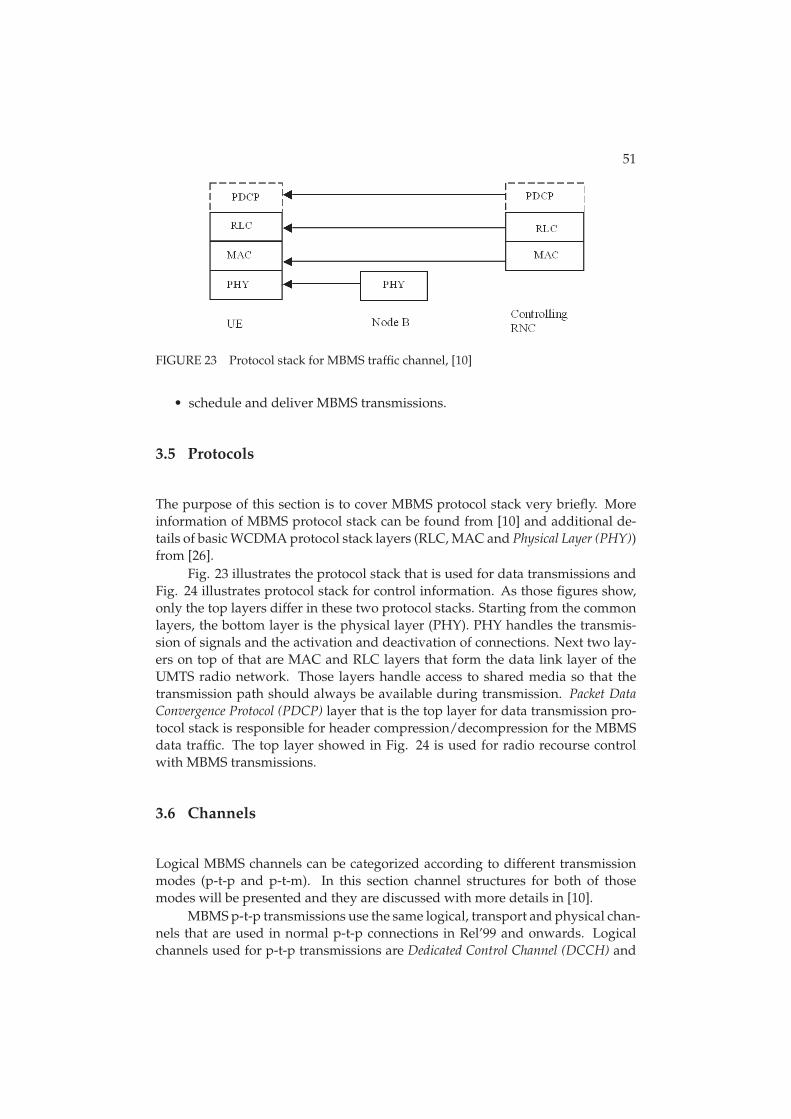
51
FIGURE 23 Protocol stack for MBMS traffic channel, [10]
• schedule and deliver MBMS transmissions.
3.5 Protocols
The purpose of this section is to cover MBMS protocol stack very briefly. Moreinformation of MBMS protocol stack can be found from [10] and additional de-tails of basic WCDMA protocol stack layers (RLC, MAC and Physical Layer (PHY))from [26].
Fig. 23 illustrates the protocol stack that is used for data transmissions andFig. 24 illustrates protocol stack for control information. As those figures show,only the top layers differ in these two protocol stacks. Starting from the commonlayers, the bottom layer is the physical layer (PHY). PHY handles the transmis-sion of signals and the activation and deactivation of connections. Next two lay-ers on top of that are MAC and RLC layers that form the data link layer of theUMTS radio network. Those layers handle access to shared media so that thetransmission path should always be available during transmission. Packet Data
Convergence Protocol (PDCP) layer that is the top layer for data transmission pro-tocol stack is responsible for header compression/decompression for the MBMSdata traffic. The top layer showed in Fig. 24 is used for radio recourse controlwith MBMS transmissions.
3.6 Channels
Logical MBMS channels can be categorized according to different transmissionmodes (p-t-p and p-t-m). In this section channel structures for both of thosemodes will be presented and they are discussed with more details in [10].
MBMS p-t-p transmissions use the same logical, transport and physical chan-nels that are used in normal p-t-p connections in Rel’99 and onwards. Logicalchannels used for p-t-p transmissions are Dedicated Control Channel (DCCH) and
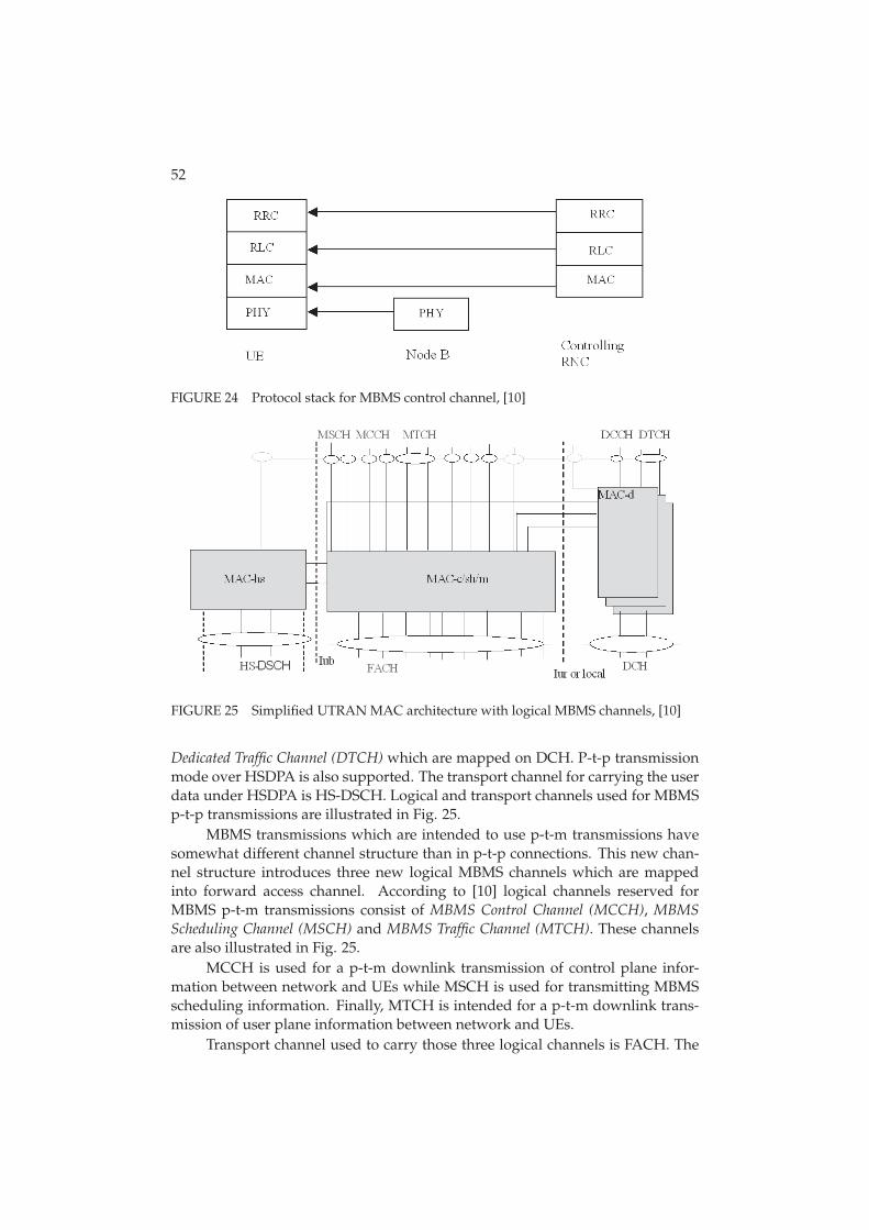
52
FIGURE 24 Protocol stack for MBMS control channel, [10]
FIGURE 25 Simplified UTRAN MAC architecture with logical MBMS channels, [10]
Dedicated Traffic Channel (DTCH) which are mapped on DCH. P-t-p transmissionmode over HSDPA is also supported. The transport channel for carrying the userdata under HSDPA is HS-DSCH. Logical and transport channels used for MBMSp-t-p transmissions are illustrated in Fig. 25.
MBMS transmissions which are intended to use p-t-m transmissions havesomewhat different channel structure than in p-t-p connections. This new chan-nel structure introduces three new logical MBMS channels which are mappedinto forward access channel. According to [10] logical channels reserved forMBMS p-t-m transmissions consist of MBMS Control Channel (MCCH), MBMS
Scheduling Channel (MSCH) and MBMS Traffic Channel (MTCH). These channelsare also illustrated in Fig. 25.
MCCH is used for a p-t-m downlink transmission of control plane infor-mation between network and UEs while MSCH is used for transmitting MBMSscheduling information. Finally, MTCH is intended for a p-t-m downlink trans-mission of user plane information between network and UEs.
Transport channel used to carry those three logical channels is FACH. The
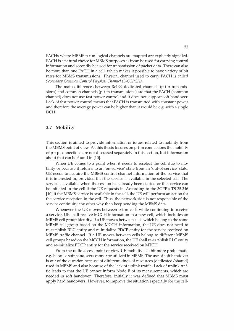
53
FACHs where MBMS p-t-m logical channels are mapped are explicitly signaled.FACH is a natural choice for MBMS purposes as it can be used for carrying controlinformation and secondly be used for transmission of packet data. There can alsobe more than one FACH in a cell, which makes it possible to have variety of bitrates for MBMS transmissions. Physical channel used to carry FACH is calledSecondary Common Control Physical Channel (S-CCPCH).
The main differences between Rel’99 dedicated channels (p-t-p transmis-sions) and common channels (p-t-m transmissions) are that the FACH (commonchannel) does not use fast power control and it does not support soft handover.Lack of fast power control means that FACH is transmitted with constant powerand therefore the average power can be higher than it would be e.g. with a singleDCH.
3.7 Mobility
This section is aimed to provide information of issues related to mobility fromthe MBMS point of view. As this thesis focuses on p-t-m connections the mobilityof p-t-p connections are not discussed separately in this section, but informationabout that can be found in [10].
When UE comes to a point when it needs to reselect the cell due to mo-bility or because it returns to an ’on-service’ state from an ’out-of-service’ state,UE needs to acquire the MBMS control channel information of the service thatit is interested in, provided that the service is available in the selected cell. Theservice is available when the session has already been started or the service canbe initiated in the cell if the UE requests it. According to the 3GPP’s TS 25.346[10] if the MBMS service is available in the cell, the UE will perform an action forthe service reception in the cell. Thus, the network side is not responsible of theservice continuity any other way than keep sending the MBMS data.
Whenever the UE moves between p-t-m cells while continuing to receivea service, UE shall receive MCCH information in a new cell, which includes anMBMS cell group identity. If a UE moves between cells which belong to the sameMBMS cell group based on the MCCH information, the UE does not need tore-establish RLC entity and re-initialize PDCP entity for the service received onMBMS traffic channel. If a UE moves between cells belong to different MBMScell groups based on the MCCH information, the UE shall re-establish RLC entityand re-initialize PDCP entity for the service received on MTCH.
From the radio access point of view UE mobility is a bit more problematice.g. because soft handovers cannot be utilized in MBMS. The use of soft handoveris out of the question because of different kinds of resources (dedicated/shared)used in MBMS and also because of the lack of uplink traffic. Lack of uplink traf-fic leads to that the UE cannot inform Node B of its measurements, which areneeded in soft handover. Therefore, initially it was defined that MBMS mustapply hard handovers. However, to improve the situation especially for the cell-

54
edge users macro diversity combining has been considered as viable option interms of MBMS, see Section 2.6.
4 VOICE OVER IP
Voice over Internet Protocol is commonly referred as technology that includesonly the transportation of speech over packet switched networks. However, inreality VoIP covers not only speech but many value added services combinationof which could be referred as rich calls. Speech or voice is indeed the main servicebut VoIP employs the possibility for video feed, presence information, instantmessaging and others. Even though VoIP brings a large variety of benefits, VoIPalso introduces some challenges to tackle with. VoIP is not tolerable for packetloss, high delays nor jitter (i.e delay variance). These challenges can be especiallyproblematic in the perspective of wireless cellular networks. The purpose of thissection is to shortly introduce VoIP, especially in terms of wireless cellular net-works.
4.1 Introduction
Voice over IP or VoIP protocols were used to carry voice signals over the earlyinternet for the first time in 1973. Those trials were for non-commercial use andthe first commercial software for end-users was made available much later in themid 1990’s. Company called Vocaltec released software called ’Internet Phone’ in1995 which did not still allow gateway to analog networks but communicationbetween other ’Internet Phone’ users was possible. Other competing companiesthat were working on similar products introduced their solutions subsequently.These included Nuera, Net2phone, Cisco, Clarent, Vienna Systems, etc. At thelate 90’s after the possibility to make also digital to analogue calls VoIP was get-ting more and more popular as people where able to make e.g. international callswith fraction of the cost of traditional calls.
VoIP-trend from the fixed networks is nowadays starting to emerge also inthe wireless cellular networks as the evolution of packet data technologies hasmade it possible to carry the voice efficiently over packet switched domain in-stead of traditional circuit switched solutions. In addition to mere technology,
56
flat rate pricing of wireless data connections has a role in pushing more and moreusers using voice over IP due to lowered costs. VoIP does not benefit only theend users as VoIP has introduced the possibility to move into All-IP networks in-stead of using separate CS network elements for voice and PS elements for data.This would lead to cost savings for the operators as the CS related part of the corenetwork would not be needed anymore. These cost savings along with the pos-sibility to implement rich call services ([25]) with less complexity have increasedinterest toward VoIP. The growing interest toward VoIP has made VoIP very likelyfeature in the cellular networks which is proven by the fact that upcoming LTEnetworks support only packet based voice.
4.2 Quality of Service
Generally requirement for successful penetration of VoIP is that the voice qualityshould be comparable to what is available using the Public Switched Telephone Net-
work (PSTN) i.e. (roughly) traditional circuit switched voice. There are numerousfactors affecting VoIP quality of service some of which are addressed shortly inthis section.
Coder Decoder (Codec) is a procedure to digitalize voice signal using as fewbits as possible still maintaining a reasonable level of speech quality. Codecshould thus work so that it gives good compression in order to save transmis-sion resources, provide good enough voice quality so that speech is still under-standable and recognizable and finally this procedure should introduce as lowadditional delay as possible so that mouth-to-ear delay does not get excessivelylong. Standardization bodies like International Telecommunication Union (ITU) and3GPP recommends the use of certain codecs, e.g. for all wide area networkingapplications ITU recommendation is G.729 codec and for cellular networks 3GPPrecommend Adaptive Multi-Rate - Wideband (AMR-WB) codec [12].
Echo cancellation is also critical to be compensated in systems where thedelay is a factor, VoIP over cellular networks is such a system. Echo is causedby reflections of the signal which can result in hearing ones own voice repeated.In other words, an echo is the audible leak-through of your own voice into yourown receive (return) path. If one-way delay exceeds 25-150 ms the echo becomesaudible and thus thus cancellation is required [18].
One of the most critical factor effecting VoIP quality is the delay. Delaycan be divided into total transmission delay and to delay jitter. Total transmis-sion delay is the sum of the compression, decompression, processing, buffer-ing/queueing, transmission delay and the network delays. According to ITUe-model [41], the maximum acceptable mouth-to-ear delay for voice is on the or-der of 250 ms as the the reference values in Fig. 26 show. In the respect of HSPAnetworks assuming the delay for core network is approximately 100 ms, the tol-erable delay for air interface should be strictly lower than 150 ms. Hence, as-suming that both users are UTRAN users, tolerable delay for RLC/MAC buffer-
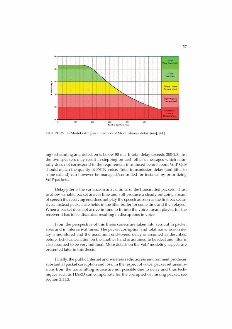
57
FIGURE 26 E-Model rating as a function of Mouth-to-ear delay [ms], [41]
ing/scheduling and detection is below 80 ms. If total delay exceeds 200-250 ms,the two speakers may result in stepping on each other’s messages which natu-rally does not correspond to the requirement introduced before about VoIP QoSshould match the quality of PSTN voice. Total transmission delay (and jitter tosome extend) can however be managed/controlled for instance by prioritizingVoIP packets.
Delay jitter is the variance in arrival times of the transmitted packets. Thus,to allow variable packet arrival time and still produce a steady outgoing streamof speech the receiving end does not play the speech as soon as the first packet ar-rives. Instead packets are helds in the jitter buffer for some time and then played.When a packet does not arrive in time to fit into the voice stream played for thereceiver it has to be discarded resulting in disruptions in voice.
From the perspective of this thesis codecs are taken into account in packetsizes and in interarrival times. The packet corruption and total transmission de-lay is monitored and the maximum end-to-end delay is assumed as describedbefore. Echo cancellation on the another hand is assumed to be ideal and jitter isalso assumed to be very minimal. More details on the VoIP modeling aspects arepresented later in this thesis.
Finally, the public Internet and wireless radio access environment producessubstantial packet corruption and loss. In the respect of voice, packet retransmis-sions from the transmitting source are not possible due to delay and thus tech-niques such as HARQ can compensate for the corrupted or missing packet, seeSection 2.11.2.
58
4.3 Protocols
Forming, maintaining and releasing VoIP calls requires both signaling and trans-port protocols. Signaling protocols are used for e.g. forming and releasing con-nections, resolving endpoint addresses and capabilities, selecting the media forthe session and conveying session state information. The most notable signal-ing protocol generally associated with VoIP is Session Initiation Protocol (SIP) [33],which has been standardized by Internet Engineering Task Force (IETF). Transportprotocols on the another hand are needed for the actual media transport. Gener-ally, IETF’s Real Time Transport Protocol (RTP) [35] is utilized as a transport proto-col. The purpose of the following subsections is to present SIP and RTP protocolsbriefly in addition to an overview of (robust) header compression which is im-perative for services such as VoIP.
4.3.1 Session Initiation Protocol
Session initiation protocol is a peer-to-peer application-layer protocol that canestablish, control, and terminate multimedia sessions with one or more partici-pants. According to Request For Comments (RFC) 3261, [33], SIP supports follow-ing five facets of establishing and terminating multimedia communications:
• User location i.e. determination of the end system to be used for communi-cation.
• User availability i.e. determination of the willingness of the called party toengage in communications.
• User capabilities i.e. determination of the media and media parameters tobe used.
• Session setup i.e. ’ringing’, establishment of session parameters at bothcalled and calling party.
• Session management including transfer and termination of sessions, modi-fying session parameters, and invoking services.
SIP is independent of the underlaying transport protocol and thus e.g. Transmis-
sion Control Protocol (TCP) or User Datagram Protocol (UDP) can be used. In addi-tion to transport protocol, SIP works in conjunction with other protocols such asSession Description Protocol (SDP) and Media Gateway Control Protocol (MEGACO)
which is used for controlling gateways to the public switched telephone network.SDP, [34], which is carried by the SIP describes the session details such as:
1. Session name and purpose,
2. Time(s) when session is active,
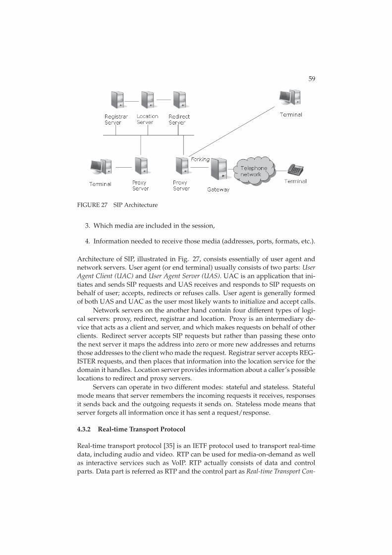
59
FIGURE 27 SIP Architecture
3. Which media are included in the session,
4. Information needed to receive those media (addresses, ports, formats, etc.).
Architecture of SIP, illustrated in Fig. 27, consists essentially of user agent andnetwork servers. User agent (or end terminal) usually consists of two parts: User
Agent Client (UAC) and User Agent Server (UAS). UAC is an application that ini-tiates and sends SIP requests and UAS receives and responds to SIP requests onbehalf of user; accepts, redirects or refuses calls. User agent is generally formedof both UAS and UAC as the user most likely wants to initialize and accept calls.
Network servers on the another hand contain four different types of logi-cal servers: proxy, redirect, registrar and location. Proxy is an intermediary de-vice that acts as a client and server, and which makes requests on behalf of otherclients. Redirect server accepts SIP requests but rather than passing these ontothe next server it maps the address into zero or more new addresses and returnsthose addresses to the client who made the request. Registrar server accepts REG-ISTER requests, and then places that information into the location service for thedomain it handles. Location server provides information about a caller’s possiblelocations to redirect and proxy servers.
Servers can operate in two different modes: stateful and stateless. Statefulmode means that server remembers the incoming requests it receives, responsesit sends back and the outgoing requests it sends on. Stateless mode means thatserver forgets all information once it has sent a request/response.
4.3.2 Real-time Transport Protocol
Real-time transport protocol [35] is an IETF protocol used to transport real-timedata, including audio and video. RTP can be used for media-on-demand as wellas interactive services such as VoIP. RTP actually consists of data and controlparts. Data part is referred as RTP and the control part as Real-time Transport Con-
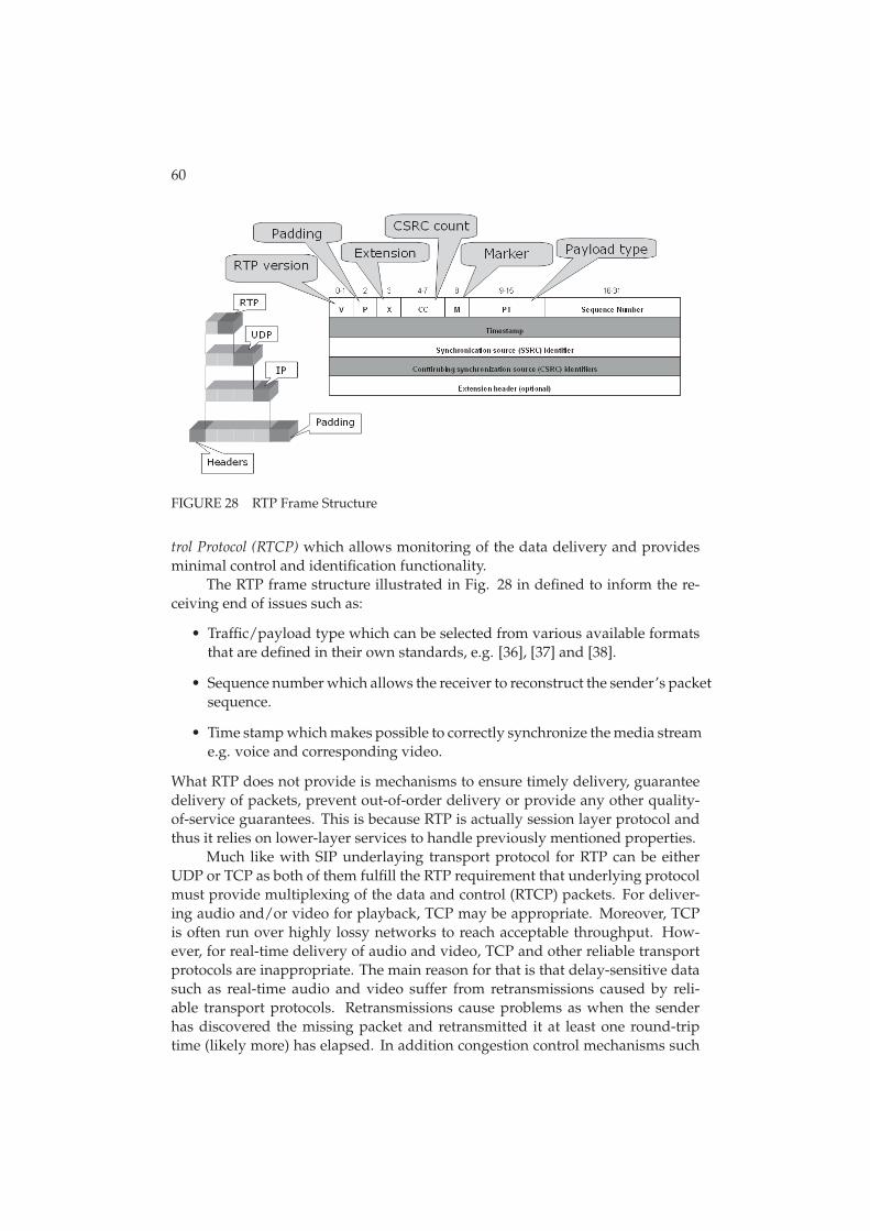
60
FIGURE 28 RTP Frame Structure
trol Protocol (RTCP) which allows monitoring of the data delivery and providesminimal control and identification functionality.
The RTP frame structure illustrated in Fig. 28 in defined to inform the re-ceiving end of issues such as:
• Traffic/payload type which can be selected from various available formatsthat are defined in their own standards, e.g. [36], [37] and [38].
• Sequence number which allows the receiver to reconstruct the sender’s packetsequence.
• Time stamp which makes possible to correctly synchronize the media streame.g. voice and corresponding video.
What RTP does not provide is mechanisms to ensure timely delivery, guaranteedelivery of packets, prevent out-of-order delivery or provide any other quality-of-service guarantees. This is because RTP is actually session layer protocol andthus it relies on lower-layer services to handle previously mentioned properties.
Much like with SIP underlaying transport protocol for RTP can be eitherUDP or TCP as both of them fulfill the RTP requirement that underlying protocolmust provide multiplexing of the data and control (RTCP) packets. For deliver-ing audio and/or video for playback, TCP may be appropriate. Moreover, TCPis often run over highly lossy networks to reach acceptable throughput. How-ever, for real-time delivery of audio and video, TCP and other reliable transportprotocols are inappropriate. The main reason for that is that delay-sensitive datasuch as real-time audio and video suffer from retransmissions caused by reli-able transport protocols. Retransmissions cause problems as when the senderhas discovered the missing packet and retransmitted it at least one round-triptime (likely more) has elapsed. In addition congestion control mechanisms such
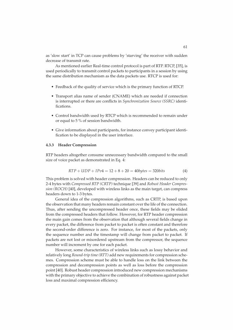
61
as ’slow start’ in TCP can cause problems by ’starving’ the receiver with suddendecrease of transmit rate.
As mentioned earlier Real-time control protocol is part of RTP. RTCP, [35], isused periodically to transmit control packets to participants in a session by usingthe same distribution mechanism as the data packets use. RTCP is used for:
• Feedback of the quality of service which is the primary function of RTCP.
• Transport alias name of sender (CNAME) which are needed if connectionis interrupted or there are conflicts in Synchronization Source (SSRC) identi-fications.
• Control bandwidth used by RTCP which is recommended to remain underor equal to 5 % of session bandwidth.
• Give information about participants, for instance convey participant identi-fication to be displayed in the user interface.
4.3.3 Header Compression
RTP headers altogether consume unnecessary bandwidth compared to the smallsize of voice packet as demonstrated in Eq. 4:
RTP + UDP + IPv4 = 12 + 8 + 20 = 40bytes = 320bits (4)
This problem is solved with header compression. Headers can be reduced to only2-4 bytes with Compressed RTP (CRTP) technique [39] and Robust Header Compres-
sion (ROCH) [40], developed with wireless links as the main target, can compressheaders down to 1-3 bytes.
General idea of the compression algorithms, such as CRTP, is based uponthe observation that many headers remain constant over the life of the connection.Thus, after sending the uncompressed header once, these fields may be elidedfrom the compressed headers that follow. However, for RTP header compressionthe main gain comes from the observation that although several fields change inevery packet, the difference from packet to packet is often constant and thereforethe second-order difference is zero. For instance, for most of the packets, onlythe sequence number and the timestamp will change from packet to packet. Ifpackets are not lost or misordered upstream from the compressor, the sequencenumber will increment by one for each packet.
However, some characteristics of wireless links such as lossy behavior andrelatively long Round-trip time (RTT) add new requirements for compression sche-mes. Compression scheme must be able to handle loss on the link between thecompression and decompression points as well as loss before the compressionpoint [40]. Robust header compression introduced new compression mechanismswith the primary objective to achieve the combination of robustness against packetloss and maximal compression efficiency.

62
FIGURE 29 ROCH state transitions
Roughly speaking, the performance of ROCH is based on three differentstates: Initialization and Refresh (IR), First Order (FO) and Second Order (SO). Tran-sitions to and from these different states is illustrated in Fig. 29.
According to [40], the purpose of the IR state is to initialize the static partsof the context at the decompressor or to recover after failure. Initialization orrecovery is done by sending the complete header information. The compressorstays in the IR state until it is fairly confident that the decompressor has receivedthe static information correctly. The purpose of the FO state is to efficiently com-municate irregularities in the packet stream. In FO state, the compressor rarelysends information about all dynamic fields, and the information sent is usuallycompressed at least partially. Compressor stays in the FO state until it is confi-dent that the decompressor has acquired all the parameters of the new pattern.Some or all packets sent in the FO state carry context updating information. It isvery important to detect corruption of such packets to avoid erroneous updatesand context inconsistencies. Finally, when SO state is used the compression isoptimal. The compressor leaves SO state and goes back to the FO state when theheader no longer conforms to the uniform pattern and cannot be independentlycompressed on the basis of previous context information.
4.4 IP Multimedia Subsystem
IP Multimedia Subsystem is an architectural framework to provide a secure andreliable means for wireless and wireline terminals and applications to reach, ne-gotiate and communicate with each other. IMS was introduced for the first timein 3GGP’s Rel’5. In the first IMS release UMTS was recognized as the only accessmethodology but later it was updated to become access independent solution[11]. Therefore, with the help of IMS one can easily deploy services to make e.g.VoIP call from cellular phone to laptop with Wireless Lan (WLAN) connection, asillustrated in Fig. 30. As IMS is highly recommended part of the architecturewhere VoIP is employed, the purpose of this section is to briefly describe coreelements and functionalities of IMS in the respect of VoIP. Further details of IMScan be acquired e.g. from [11] and [22].
Roughly speaking, IMS is a horizontal control layer that isolates the accessnetwork from the service layer and specifies interfaces that services can utilizeeasily, as depicted in Fig. 31. IMS tries to utilize the IETF’s ’Internet standards’ asfar as possible for the cases where an IETF protocol has been selected. SIP is anexample of IETF protocol that is supported by IMS.
As Fig. 31 illustrates the core of IMS comprises of two main nodes: the

63
FIGURE 30 Example of IMS system, [27]
FIGURE 31 IMS Architecture overview, [22]
Call Session Control Function (CSCF) and the Home Subscriber Server (HSS). In or-der to be able to provide connections to analogue telephone networks IMS can beconnected to General Switched Telephony Network (GSTN) or PSTN through inter-working functions by Media Gateway Control Function (MGCF) and Media Gateway
(MGW).The main function of the CSCF is to manage the SIP sessions and coordinate
with other network elements for session control, application/service control andresource allocation. CSCF has also the responsibility for interacting with the HSSwhich is responsible for identification handling, access authorization, authenti-cation, mobility management in addition to support for session establishment,service provisioning and service authorization. As shown in Fig. 32 CSCF canplay three different roles: Serving-, Interrogating and Proxy- Call Session Control
Function (S-, I- and P-CSCF) to handle previously presented tasks.S-CSCF is the central node of the signaling plane. It provides the mechanism
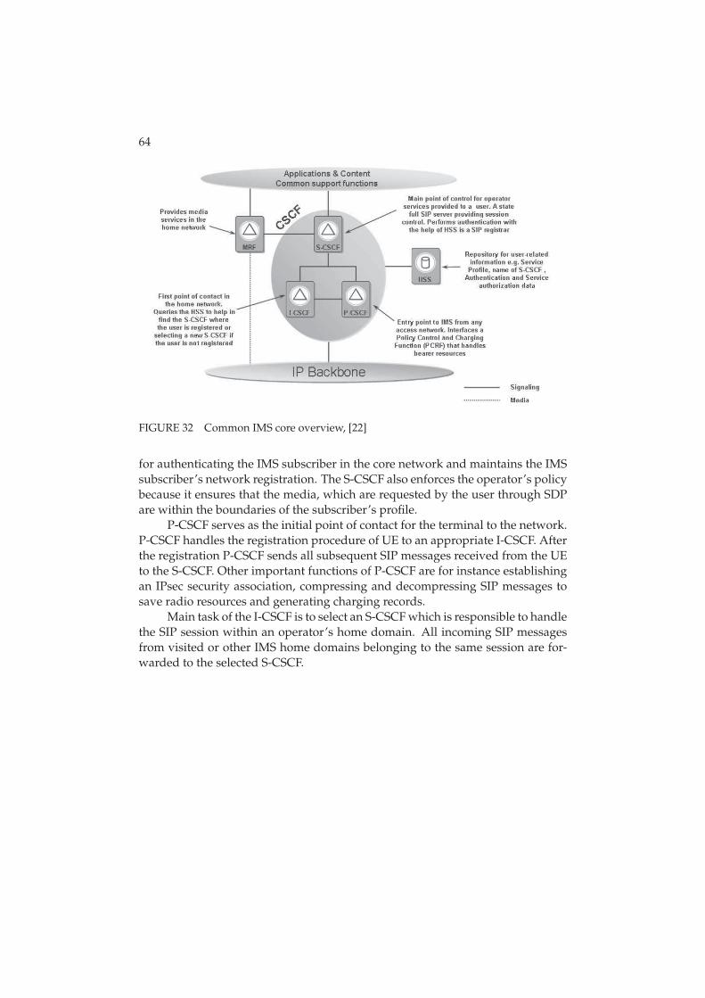
64
FIGURE 32 Common IMS core overview, [22]
for authenticating the IMS subscriber in the core network and maintains the IMSsubscriber’s network registration. The S-CSCF also enforces the operator’s policybecause it ensures that the media, which are requested by the user through SDPare within the boundaries of the subscriber’s profile.
P-CSCF serves as the initial point of contact for the terminal to the network.P-CSCF handles the registration procedure of UE to an appropriate I-CSCF. Afterthe registration P-CSCF sends all subsequent SIP messages received from the UEto the S-CSCF. Other important functions of P-CSCF are for instance establishingan IPsec security association, compressing and decompressing SIP messages tosave radio resources and generating charging records.
Main task of the I-CSCF is to select an S-CSCF which is responsible to handlethe SIP session within an operator’s home domain. All incoming SIP messagesfrom visited or other IMS home domains belonging to the same session are for-warded to the selected S-CSCF.
5 ACHIEVED RESULTS
The purpose of this chapter is to first provide understanding of the used researchtool and research scenario. After providing basic understanding of those issuesthis chapter presents analysis on the basis of achieved results.
5.1 Research Tool
The research tool used to perform studies regarding this thesis is a comprehen-sive dynamic WCDMA/HSPA radio network simulator. Simulator is designedfor studying RRM algorithms in order to obtain capacity and coverage estimates,to support standardization work and network planning by optimizing and tun-ing the radio network parameters. Simulation tool enables detailed simulationof users in multiple cells with realistic call generation, propagation, fading andmobility models (adopted from [13]).
There are at least two factors advocating the usage of dynamic system simu-lations: on the one hand, the complexity of the dynamic network behavior makesit virtually impossible to calculate accurate analytical results, and on the otherhand, physical network trials would be time consuming and expensive. Thus,fully dynamic system level simulations where user mobility, RRM functionalitiesand their inter-actions are taken explicitly into account are essential to the perfor-mance evaluations. Moreover as the used simulator is highly configurable withparameters for network traffic, mobile terminals, network configuration, RRM al-gorithms and physical layer in addition to vast expandability possibilities it trulyis an indispensable tool for studying radio network performance and possibleenhancements.
Implementation of the used simulator itself is a compromise between build-ing an accurate model of a WCDMA/HSPA network and keeping manageablecomputing efforts. In order to keep computing efforts on reasonable levels andto reduce the complexity of the simulator, simulator has been divided into linkand system level simulators. In link level simulator connection between one UE
66
and base station is modeled in very detailed level. Then produced link level dataof receiver Frame Error Rate (FER) (or Bit Error Rate (BER)) performance is usedthrough a so called Actual Value Interface (AVI) in the system level simulator aspresented in [32].
Simulation flow includes three fundamental phases:
1. Setup
2. Simulation
3. Destruct
During first phase all of the objects including the simulation scenario, RNCs,Node Bs and UEs are generated according to user defined parameters. In thesecond phase the actual simulation procedure is completed which starts witha warm up period. Warm up period generates the initial load for the networkwhich should reach the level of realistic network. The gathering of statistics startsafter the warm up period. Simulation runs in slot resolution i.e. in every 0, 667ms all relevant actions and statistic gathering are performed. Relevant actionsin every simulation slot contain e.g. interference calculation between all activeconnections, measurements for handover and power control and so on. All ele-ments involved in simulated system (UEs, Node Bs, RNCs) go through their ownactions before control is moved to the next time slot. The second phase will be ac-tive until the user defined last time slot is reached. In the end, final statistics willbe saved and then the simulation is finished by destroying all created elements,referred as third phase.
The modeling and reliability analysis of the used dynamic system simulatorhas been presented earlier in many international articles and conferences, see e.g.[31] and [57], as well as in doctoral theses such as [45], [42] and [30]. The reliabilityanalysis for this thesis is addressed (mainly) in the Appendix 1 at the end of thisthesis. The purpose of the following sections is to address modeling issues fromthe perspective of MBMS and VoIP.
5.1.1 MBMS Modeling
MBMS sessions and subscribers
Simulator supports static and dynamic call setup processes for MBMS i.e. thenumber of terminals/calls can either stay static for the duration of the simula-tion or change dynamically. Dynamic number of terminals/call is defined by thenumber of subscribers, call arrival rate and average call length.
Also, from the perspective of MBMS sessions, two alternatives exist. Thewhole duration of simulation can be considered as one MBMS session or it canconsist of multiple MBMS sessions. If the whole simulation duration is consid-ered as one MBMS session then in the beginning of the simulation static numberof terminals are created, which model the users who have subscribed the MBMSservice. All the calls last as long as the simulation lasts and thus the MBMS ser-vice ends when the simulation ends. In the other alternative, in the beginning of
67
the simulation static number of terminals are created, which again presents theusers who have subscribed to MBMS service. Fixed MBMS service duration i.e.call duration is defined for each terminal. All calls end at the same time, thus thenew MBMS service and the new calls start immediately after the previous servicehas ended. Similar simulation scenarios can be applied to dynamic number ofsubscribers as well. This thesis assumes static number of terminals and multi-ple MBMS sessions during one simulation run in order to guarantee satisfactorynumber of samples to analyze the results.
MBMS transmission and reception
For each sector MTCH is created and it is has a constant transmit power. MTCH’spower is thus taken into account in interference calculations. MTCH is modeledsimilarly as Common Pilot Channel (CPICH) i.e. only the transmitter i.e. Node Bside is defined for that channel. Certain power allocation can also be reservedfor MCCH. However, in these studies MCCH power is assumed to be part of theother common channels.
Reception of MTCH data can be done from a single or multiple cells/sectorsto model soft and selective combining which were presented in Section 2.6. If thereception is done from multiple cells/sectors those cells/sectors are referred ascombining set. Combining set update procedure for MBMS p-t-m transmissionsis much like the ordinary soft handover, see Section 2.9.3. The difference to softhandover is that the UE does not send any measurement reports to the networkside but independently decides, according to filtered pilot measurements, fromwhich sectors it receives and combines signals. Due to the fact that combining setupdate procedure is very much like soft handover same terminology is used inthis thesis when concerning issues related to the combining set update procedure.Parameterized delay is also modeled for combining set updates i.e. combining setupdate events are held in the delay queue according to delay parameter beforeactual combining set update is done.
5.1.2 VoIP Modeling
VoIP traffic
The VoIP traffic model that is assumed in this thesis is illustrated in Fig. 33. Themain features of the model are:
• Duration of each call is random and distributed according to negative ex-ponential distribution. The mean value of the distribution is given as aparameter.
• DTX is simulated through alternating, random duration activity and silenceperiods. The duration of these periods is distributed according to negativeexponential distribution. Mean length of the activity/silence periods can beadjusted through the parameters.

68
FIGURE 33 Example of VoIP traffic model
• A probability to start the VoIP call in silence can be set through the param-eters.
• During activity periods, a new VoIP packet is generated on constant in-tervals. Size of the packet packet (including payload and RTP, UDP, IPand other headers) is given in the parameters as well as the time intervalbetween successive packets (e.g. 38 byte packet every 20 ms). ROCH isnot modeled explicitly but assumed as ideal and thus taken into account inpacket sizes
For a telephone conversation there are silent intervals between speech frames,referred as silence in Fig. 33. During silent intervals SID frames are sent in orderto maintain the connection. SID frames contain information needed to generatebackground (comfort) noise. They are sent in the beginning of the silent periodand every 160 ms during the silence.
VoIP calls
In order to be able to evaluate how many users can be served in a cell beforeQoS criteria is exceed and users become unsatisfied, a static number of users percell are assumed. By simulating different loads i.e. amounts of users/cell andanalyzing the QoS with each user amount the estimate of cell capacity in termsof VoIP can be interpolated. Users are placed uniforminly around the simulationarea.
Quality of Service monitoring
Quality of service for VoIP calls is monitored through sliding window period.During that monitoring period, if at least a certain percentage of packets, givenas a parameter, are not received correctly within a delay criteria, also given as aparameter, a flag to mark that call as unsuccessful is raised. At the end of eachcall the flag in question is checked and if it has been raised in any point of the call,the call is counted to be in outage. In addition, a VoIP call can be dropped if thequality of the transmission drops significantly. Dropping of VoIP calls is based
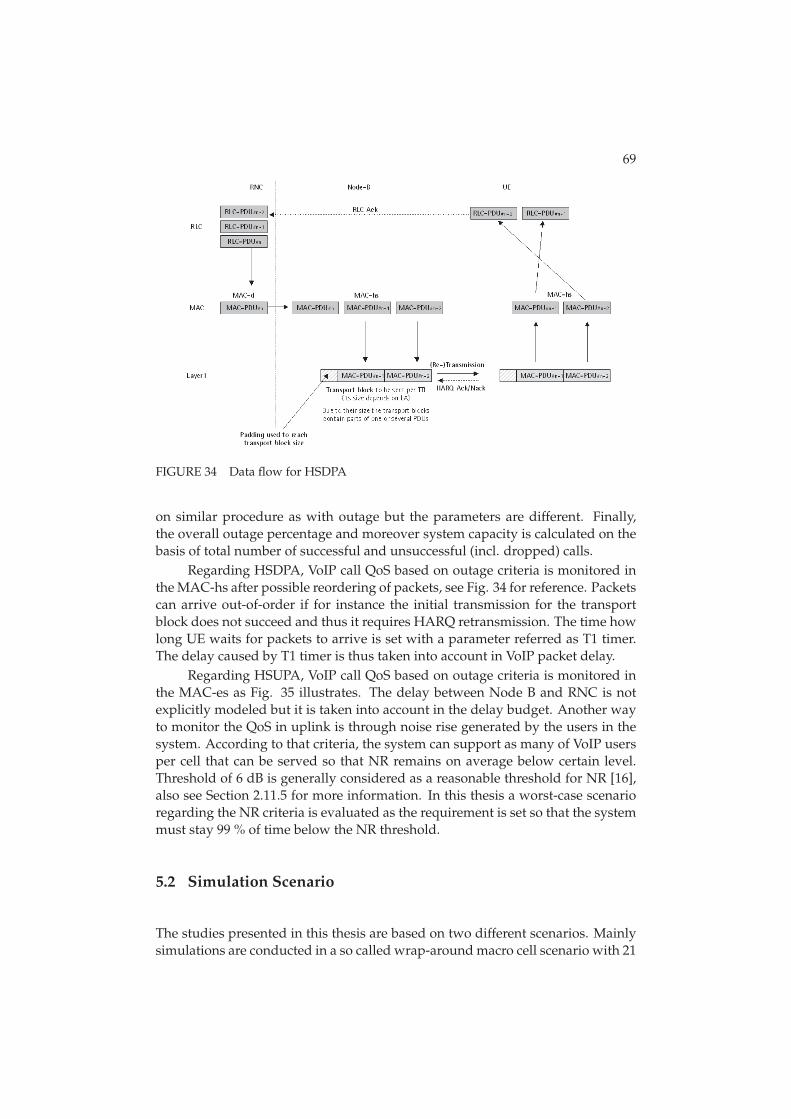
69
FIGURE 34 Data flow for HSDPA
on similar procedure as with outage but the parameters are different. Finally,the overall outage percentage and moreover system capacity is calculated on thebasis of total number of successful and unsuccessful (incl. dropped) calls.
Regarding HSDPA, VoIP call QoS based on outage criteria is monitored inthe MAC-hs after possible reordering of packets, see Fig. 34 for reference. Packetscan arrive out-of-order if for instance the initial transmission for the transportblock does not succeed and thus it requires HARQ retransmission. The time howlong UE waits for packets to arrive is set with a parameter referred as T1 timer.The delay caused by T1 timer is thus taken into account in VoIP packet delay.
Regarding HSUPA, VoIP call QoS based on outage criteria is monitored inthe MAC-es as Fig. 35 illustrates. The delay between Node B and RNC is notexplicitly modeled but it is taken into account in the delay budget. Another wayto monitor the QoS in uplink is through noise rise generated by the users in thesystem. According to that criteria, the system can support as many of VoIP usersper cell that can be served so that NR remains on average below certain level.Threshold of 6 dB is generally considered as a reasonable threshold for NR [16],also see Section 2.11.5 for more information. In this thesis a worst-case scenarioregarding the NR criteria is evaluated as the requirement is set so that the systemmust stay 99 % of time below the NR threshold.
5.2 Simulation Scenario
The studies presented in this thesis are based on two different scenarios. Mainlysimulations are conducted in a so called wrap-around macro cell scenario with 21
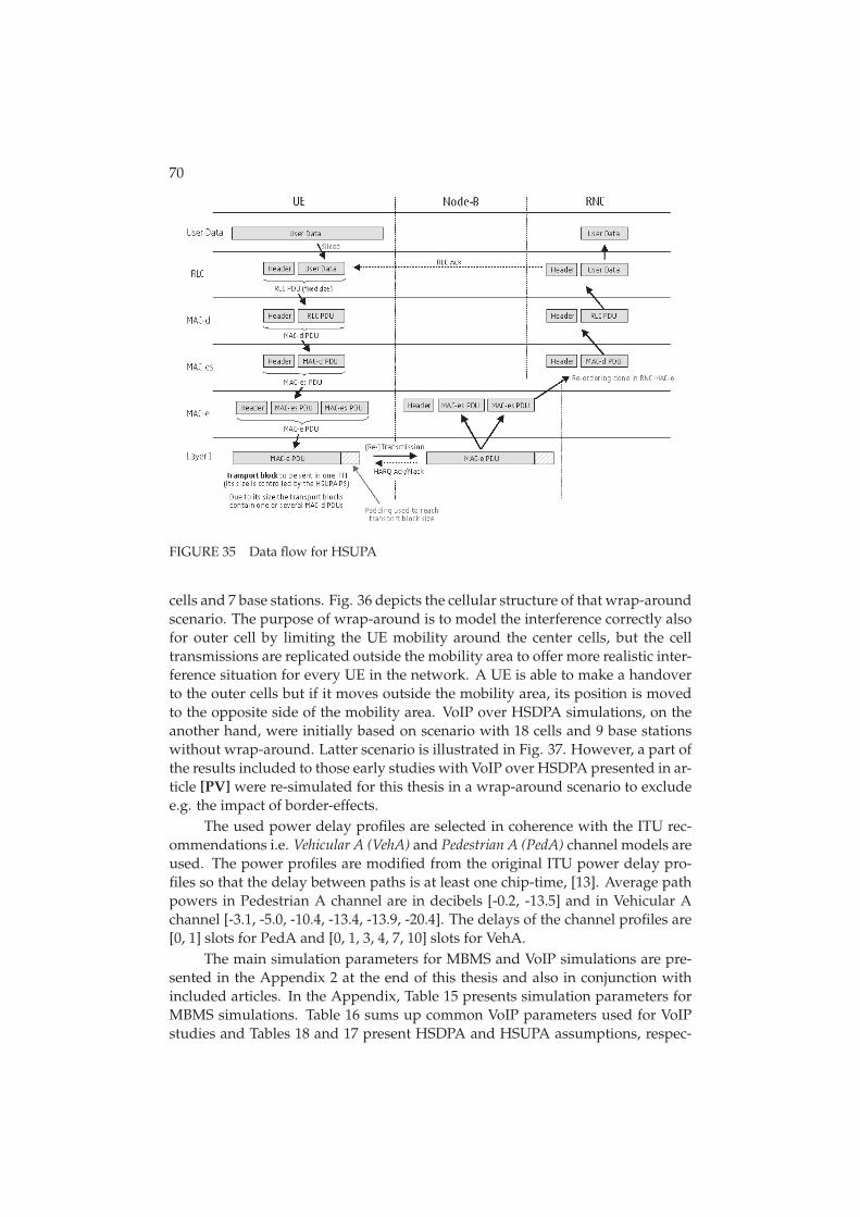
70
FIGURE 35 Data flow for HSUPA
cells and 7 base stations. Fig. 36 depicts the cellular structure of that wrap-aroundscenario. The purpose of wrap-around is to model the interference correctly alsofor outer cell by limiting the UE mobility around the center cells, but the celltransmissions are replicated outside the mobility area to offer more realistic inter-ference situation for every UE in the network. A UE is able to make a handoverto the outer cells but if it moves outside the mobility area, its position is movedto the opposite side of the mobility area. VoIP over HSDPA simulations, on theanother hand, were initially based on scenario with 18 cells and 9 base stationswithout wrap-around. Latter scenario is illustrated in Fig. 37. However, a part ofthe results included to those early studies with VoIP over HSDPA presented in ar-ticle [PV] were re-simulated for this thesis in a wrap-around scenario to excludee.g. the impact of border-effects.
The used power delay profiles are selected in coherence with the ITU rec-ommendations i.e. Vehicular A (VehA) and Pedestrian A (PedA) channel models areused. The power profiles are modified from the original ITU power delay pro-files so that the delay between paths is at least one chip-time, [13]. Average pathpowers in Pedestrian A channel are in decibels [-0.2, -13.5] and in Vehicular Achannel [-3.1, -5.0, -10.4, -13.4, -13.9, -20.4]. The delays of the channel profiles are[0, 1] slots for PedA and [0, 1, 3, 4, 7, 10] slots for VehA.
The main simulation parameters for MBMS and VoIP simulations are pre-sented in the Appendix 2 at the end of this thesis and also in conjunction withincluded articles. In the Appendix, Table 15 presents simulation parameters forMBMS simulations. Table 16 sums up common VoIP parameters used for VoIPstudies and Tables 18 and 17 present HSDPA and HSUPA assumptions, respec-
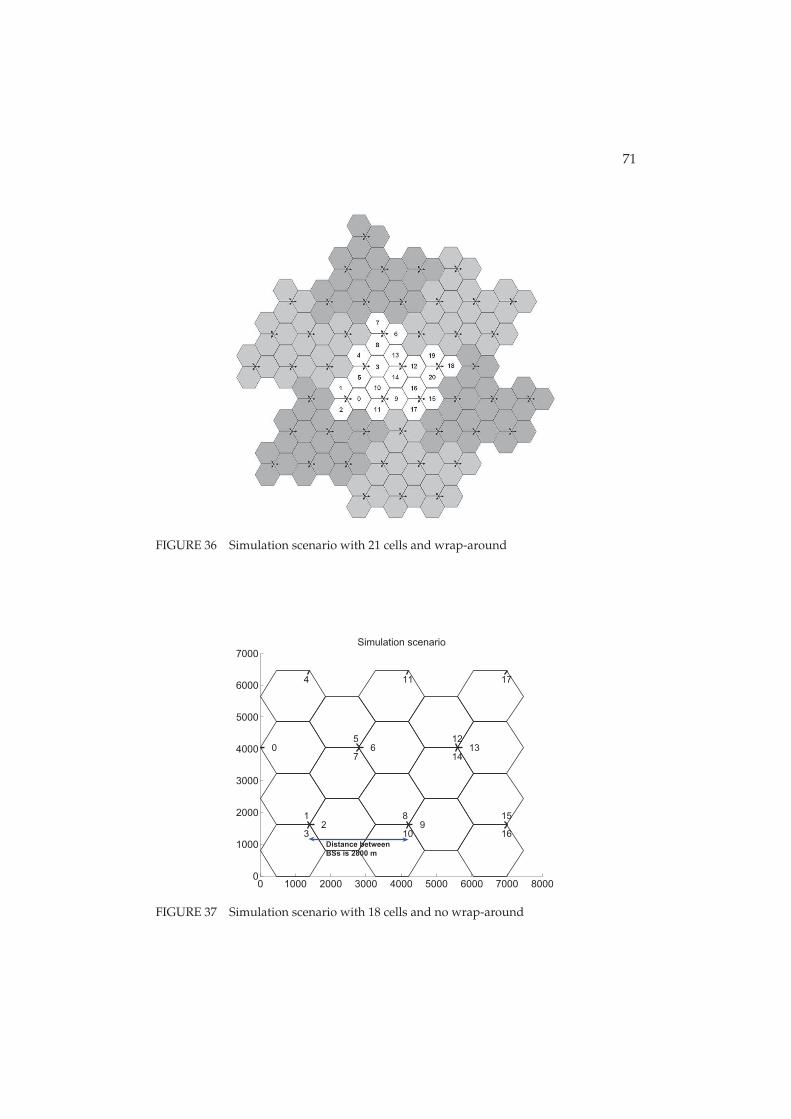
71
FIGURE 36 Simulation scenario with 21 cells and wrap-around
0 1000 2000 3000 4000 5000 6000 7000 80000
1000
2000
3000
4000
5000
6000
7000
0
12
3
4
56
7
89
10
11
1213
14
15
16
17
Simulation scenario
Distance between
BSs is 2800 m
FIGURE 37 Simulation scenario with 18 cells and no wrap-around
72
tively.
5.3 Simulation Result Analysis
The object of this thesis is to first analyze MBMS performance in WCDMA net-works and after that address how Voice over IP can perform in HSPA evolutionof WCDMA networks. Both MBMS and VoIP are key technologies when packetbased cellular networks are considered. However, by introducing these servicesinto the wireless cellular networks, new range of challenges can be encountered.The purpose of this thesis is to address some of those challenges, especially re-garding user’s mobility in the network. The following sections present the mainfindings of this thesis.
5.3.1 Macro diversity combining impact to the MBMS performance
Macro diversity and how it impacts to the MBMS p-t-m performance in WCDMAnetworks was presented in included articles [PI] and [PIII]. Article [PII] ad-dressed the performance of MBMS together with macro diversity combining andreceive diversity.
Studies indicated that macro diversity combining can improve MBMS per-formance significantly. By adding merely one link into the combining set roughly5 dB gain with soft combining and 3 dB gain with selective combining (in Ve-hicular A channel) can be acquired when compared to situation without combin-ing. Moreover, the results showed that even if MBMS terminals would be ableto utilize receive diversity macro diversity combining still brought quite signif-icant gain to the performance. Gain acquired from macro diversity was foundto be depended on the amount of links in the combining set which can be con-trolled in some sense by adjusting combining thresholds. Studies demonstratedthat soft combining provides more gain than selective combining due to fact thatsoft combining benefits also from poor links whereas selective combining benefitsonly from good links.
5.3.2 Impact of Receive Diversity to MBMS performance
MBMS performance studies in WCDMA networks were extended in articles [PII]
and [PIII] to cover the situation where terminals would be deployed with tworeceive antennas instead of one. Traditionally multiple antennas have not beenemployed in smallest handheld devices due to size and cost constraints. How-ever, receive diversity is one of the most efficient diversity techniques, since inaddition to the diversity gain the received combined signal power is theoreticallydoubled with two receive antennas when compared to single antenna reception.
Simulation results showed that receive diversity can bring substantial bene-fit for MBMS transmissions. The gain of 2Rx over 1Rx was roughly 4 dB depend-
73
ing on the other simulation parameters. Moreover, as mentioned already before,even though receive diversity itself brings quite significant gain it was also shownthat by utilizing macro diversity MBMS p-t-m performance can be enhanced evenmore.
5.3.3 MBMS with Transmit Diversity
Transmit diversity is also considered as one way to improve the transmissioncapacity. It exploits the principle of providing the receiver with multiple fadedreplicas of the same information-bearing signal. The impact of transmit diversitywith MBMS was studied in article [PIII].
The results of that study showed that transmit diversity narrows Es/No dis-tribution and provides slight improvement to lower tail of Es/No distributionwith and without soft combining. In terms of coverage this slight improvementleads to around 2 dB gain without combining. The gain was reduced to less than1.5 dB with soft combining due to the presence of additional source for diversity.
5.3.4 Battery saving opportunities with MBMS 2Rx terminals
When network is dimensioned to 1Rx and the system contains also 2Rx terminalspower savings opportunities can in theory be accomplished by switching off ad-ditional receiver branches when radio conditions allow. Possibilities for powersaving opportunities was addressed in article [PIII].
The study demonstrated that it is indeed possible to achieve very similarcoverage levels with MBMS in situations where UE is either allowed to reconfig-ure between 1Rx Rake and 2Rx Rake receiver or to use only 2Rx Rake receiver. Tohave this similarity in coverage levels one only needs to have suitable switchingthresholds and C/I filtering windows in use. Apart from similar network per-formance, antenna usage statistics indicated that there is possibility to spend asignificant amount of time using the 1Rx Rake configuration. This phenomenonsuggests that there are definite power saving opportunities relative to a UE using2Rx Rake continuously.
5.3.5 VoIP over HSUPA performance
Uplink is considered most often to limit the overall coverage of services due tofact that uplink direction is dominated by small handheld power limited termi-nals and high interference levels. Moreover, if speech service is considered thenin ’worst-case-scenario’ the cell can be very highly loaded with terminals and ifmobility is also taken into account more challenges can be faced. Packet basedvoice service i.e. Voice over IP performance was studied over HSUPA in article[PIV]. The article included studies with various handover delays, active set sizesand user velocities. Additionally, the impact of SID frames was studied.
The study indicated that the system performance can be highly affected byuser’s mobility. Handover delay proved to have rather minor impact on the per-

74
formance with low user velocities as the performance loss remained within 10 %provided that the delay stayed within reasonable limits. The difference between asingle link and two-way soft handover performance was quite noticeable. How-ever, limiting the active set size was observed to reduce the VoIP capacity onlyslightly as long as at least two links were allowed in the active set. In addition,silence indication frames specified for VoIP caused only a slight additional per-formance loss in mobility scenarios.
5.3.6 VoIP over HSDPA performance
With HSDPA only hard handover is supported which can result into excessivepacket losses and delays if handover is not executed in time or on the anotherhand is executed too often. The impact of serving HS-DSCH cell change proce-dure along with different user velocities and cell change execution delays wasaddressed in article [PV].
The simulation results indicated moderate sensitivity of VoIP capacity to theUE velocity. Very high velocities lead to more noticeable capacity loss for VoIPover HSDPA. However, tuned handover parametrization for different velocitiesmight provide better performance but it would require some mechanisms for UEspeed detection. The results showed also that handover delays started to havesignificant effect only at UE velocity of 50 km/h or more. Reliability of handoversignaling i.e. situation where handover command is actually sent over the airwas concluded not to pose problems.
Quite recently VoIP over HSDPA studies were re-opened to study e.g. powerconsumption related matters. As quite considerable amount of time had pastfrom the studies presented in article [PV] the simulator had also undergone someupdates. The updated version of the simulator includes more detailed modelingof mobility, HSDPA and VoIP. In addition, support for wrap-around scenario wasprovided along with the updated version. Due to these changes, performancebenchmarking between old and revised results was made.
Comparison between updated results and the results presented in article[PV] is illustrated in Fig. 38 in terms of user velocity. As that figure shows theabsolute capacity numbers are somewhat improved with the updated simulatorversion, however depending heavily on the user velocity and thus of the han-dover performance which was revised in the new version. For instance, with 3km/h the capacity numbers are still in the same order the difference being onlycouple of UEs/cell but for higher velocities the VoIP over HSDPA capacity ishigher than before. Therefore, also the relative drop caused by user velocity issomewhat lower than before. However, the overall conclusion of article [PV]
about UE velocity having moderate sensitivity to VoIP capacity still applies. Theimpact of delay between the two simulator versions is illustrated in Fig. 39. Asthat figure shows, again the low velocities are practically unchanged but withhigher velocities the absolute numbers are higher with the new version. How-ever, the relative impact of the delay stays in the same order as before and thusthe conclusions apply on that matter as well.
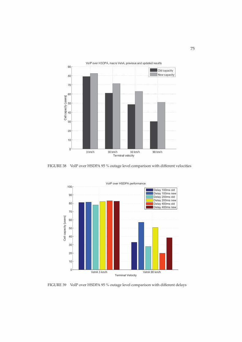
75
FIGURE 38 VoIP over HSDPA 95 % outage level comparison with different velocities
VehA 3 km/h VehA 90 km/h0
10
20
30
40
50
60
70
80
90
100
Terminal Velocity
Cell
capacity [users
]
VoIP over HSDPA performance
Delay 100ms old
Delay 100ms new
Delay 200ms old
Delay 200ms new
Delay 400ms old
Delay 400ms new
FIGURE 39 VoIP over HSDPA 95 % outage level comparison with different delays

6 CONCLUSIONS
The purpose of this thesis was to address the performance of MBMS VoIP ser-vices in WCDMA/HSPA networks. This thesis elaborated that MBMS and VoIPservices have already gained vast popularity in the fixed networks and thus itis very likely that they will also be key concepts in wireless cellular networks inthe near future. However, from practical perspective, wireless network sets verystrict environment for this kind of services. Thus, this thesis aimed to evaluatethe need of radio resources, possible enhancements and vast number of practicalnetwork parameters so that cellular network and these services operate in opti-mal manner in different situations. Special attention was be paid on the mobilityaspect of both of those services. This thesis evaluated the performance with helpof fully dynamic system simulator where user mobility, fading, propagation andRRM functionalities are explicitly taken into account.
This thesis showed that MBMS can benefit significantly from macro diver-sity combining. Macro diversity i.e. combining transmissions from multiplesources is likely option for MBMS performance improvement as MBMS is ex-pected to be available through large parts of the network. In addition to macrodiversity, also receive diversity was found to be very efficient method to improvethe performance of MBMS. However, mobile terminals with two or more receiveantennas are not likely be among the first devises to support MBMS but start toemerge slowly which means that the networks are likely to be dimensioned to1Rx terminals. Thus, this thesis showed that when the network is optimized for1Rx then 2Rx terminals can have power saving opportunities and still have highQoS by turning off the other receive antenna in good channel conditions.
The results presented by this thesis also showed the sensitivity of VoIP tohandover/active set update delays. Delays were found to be rather small if theuser velocity is low. However, when the terminals are moving at high speedsthen the delays start to have an impact. This was found to be caused by the factthat with high speed the serving link is deteriorating much faster and thus thehandover procedure should be faster. With the respect of VoIP over enhanceduplink it was concluded that the cell capacity is not limited by uplink as long assoft handover is supported. Finally, this thesis showed that VoIP capacity can

77
suffer quite a bit if all of the terminals would be moving at very high speeds.Thus, at the end of the day these issues needs to be taken into account e.g. in thenetwork planning to avoid some of the potential problems this thesis raised.
YHTEENVETO (FINNISH SUMMARY)
Ensimmäiset kolmannen sukupolven langattomat matkaviestinverkot otettiin kau-palliseen käyttöön vuonna 2002. Nämä verkot pohjautuvat pääasiassa WCDMA-tekniikkaan (engl. Wideband Code Division Multiple Access), joka mahdollis-taa käytössä olevan taajuuden tehokkaamman käytön. Siinä missä toisen suku-polven (2G) verkot tarjosivat pääasiassa mahdollisuuden puheliikenteelle, 3G-verkot mahdollistivat ensimmäistä kertaa innovatiivisten pakettipohjaisten pal-veluiden tarjoamisen matkaviestinverkoissa. Mahdollisten palveluiden kirjo laa-jeni entisestään, kun kolmannen sukupolven verkkojen suorituskykyyn esiteltiinlaajennukset, jotka tarjoavat entistä suurempia tiedonsiirtonopeuksia ja pienem-piä vasteaikoja. Nämä evoluutiot kulkevat nimellä HSDPA (engl. High SpeedDownlink Packet Access) ja HSUPA (engl. High Speed Uplink Packet Access) taijos viitataan yhteisesti molempiin HSPA (engl. High Speed Packet Access). Odo-tetusti WCDMA- ja HSPA-verkkojen suosio on kasvanut lähes räjähdysmäises-ti, sillä vuoden 2004 lopussa WCDMA-tilaajia oli 17 miljoonaa, mutta jo vuoden2008 ensimmäisen neljänneksen aikana tilaajia oli jo yli 250 miljoonaa. Tulevai-suudessa käyttäjien määrän uskotaan kasvavan entisestään, sillä kasvua vauh-dittaa alati laajeneva kirjo innovatiivisia palveluita aina videokuvan siirrosta jatv-lähetyksistä erilaisten interaktiivisten palveluiden tarjoamiseen.
Tässä lisensiaatintyössä tutkittiin erityisesti pakettiliikenteeseen perustuvanpuheliikenteen (Voice over IP) toimintaa HSPA-verkoissa sekä ryhmälähetyksiäkäsittelevän MBMS-tekniikan (engl. Multimedia Broadcast Multicast Service) suo-rituskyvyn ja sen parannuksien analysointia WCDMA-verkoissa. Matkaviestin-verkkojen puolella tällaiset tekniikat tarjoavat myös uusia näkökulmia verrattunakiinteisiin verkkoihin. Esimerkiksi VoIP-puheluiden ja sen mahdollistamien lisä-palveluiden tuominen osaksi matkaviestinverkkoja tarjoaa operaattoreille mah-dollisuuden aivan uudenlaisiin tulovirtoihin sekä mittaviin kustannussäästöihinsiinä valossa, ettei tällöin enää tarvittaisi erillistä piirikytkentäistä verkkoa pu-heelle. Kuitenkin samalla langaton matkaviestinverkko asettaa näille palveluillehyvin kriittiset toimintaolosuhteet, jonka tuomiin haasteisiin tämä lisensiaatintyöpyrkii vastaamaan.
Tutkimusmenetelmänä käytettiin ohjelmistopohjaista radioverkkosimulaat-toria, jolla pyritään mallintamaan reaalimaailman matkaviestinjärjestelmää hy-vin tarkasti. Simulaattorissa käytetyt mallit ovat yleisesti hyväksyttyjä ja tunnet-tuja. Simulaattorin mallinnusta ja aikaisempia tuloksia on esitelty lukuisissa kan-sainvälisissä tieteellisissä konferensseissa ja lisäksi mm. kolmessa väitöskirjassa.
Yksityiskohtaisemmin sanottuna tutkimustyö kohdistui MBMS:n suoritus-kyvyn analysointiin WCDMA-verkoissa mahdollisten toimintaa parantavien tek-niikoiden kanssa. Suorituskykyä arvioitiin pääasiassa ensimmäisten 3G-laitteidennäkökulmasta, ja täten HSPA-evoluutioiden tuomia näkökulmia ei erikseen käsi-telty. Makro-, lähetys- ja vastaanotindiversiteetti olivat niiden tekniikoiden jou-kossa, jotka sisältyivät tutkimuksen liikkuvuuteen liittyvien MBMS-parametrienoptimoinnin lisäksi. Makrodiversiteetti tarkoittaa yksinkertaistettuna sitä, että eri

79
tukiasemista tulevat lähetykset yhdistetään päätelaitteessa, jotta signaalin laatuavoidaan merkittävästi parantaa. Lähetys- ja vastaanotindiversiteetit taas tarkoit-tavat tilannetta, jossa lähetys- ja/tai vastaanottopäähän lisätään antenneja pa-rantamaan suorituskykyä. Työn tuloksien perusteella makrodiversiteetti on erin-omainen keino parantaa MBMS:n suorituskykyä. Vastaanotindiversiteetti lisäsimyös MBMS-käyttäjien tyytyväisyyttä merkittävästi makrodiversiteetin kanssatai ilman.
VoIP-tekniikan suorituskyvyn osalta erityisenä kiinnostuksen kohteena tut-kimuksessa oli VoIP-lähetyksien käyttäytyminen yhteisvastuunvaihtojen (engl.handover) yhteydessä. VoIP-liikenteen käyttäytyminen siirryttäessä tukiaseman/-asemien peittoalueelta toiselle, eli yhteisvastuuvaihtojen yhteydessä, on erityistähuomiota vaativaa, sillä VoIP on hyvin kriittinen kaikille ylimääräisille viiveil-le sen reaaliaikaisuuden vuoksi. Tässä lisensiaatintyössä esitettyjen tuloksien pe-rusteella voidaan todeta, että pienillä nopeuksilla kohtuulliset ylimääräiset vii-veet yhteisvastuuvaihtojen aikana eivät tuota ongelmia. Kuitenkin suuremmillanopeuksilla yhteisvastuuvaihdot pitäisi toteutua merkittävästi nopeammin, jottasuorituskyky säilyy hyvänä. Yleisesti ottaen nopeuden vaikutus VoIP-tekniikansuorituskykyyn todettiin olevan suhteellisen merkittävä, joten tämä on huomioi-tava esimerkiksi verkkoja suunniteltaessa.
APPENDIX 1 RELIABILITY ANALYSIS
Dynamic system simulator, which was used as a research tool in this thesis waspresented briefly in Section 5.1 and, for instance, in [30], [42] and [45] the tool isverified and presented in very detailed level. This appendix is aimed to give thestatistical confidence on simulation results presented in this thesis.
Statistical analysis is based on evaluating the performance with differentseeds in selected test cases. Simulation seed is a parameter to a random numbergenerator. Based on the seed a random e.g. starting position and direction ofmovement is generated for each UE. In addition to this there are several otherrandom number generators used in the simulations which will change if seed ischanged. However, even though all of the simulation results depend on randomprocesses, the results are reproducible with certain level of accuracy which isdefined in this appendix.
An interval estimation can be used to define a confidence interval, whichmeans that the sample, φ, is within a defined interval with a certain probability,i.e.
P(a ≤ φ ≤ b) = 1 − α (5)
where the interval [a, b] is a (1− α)× 100% confidence interval of φ. A probabilitythat the φ is not within the interval is α. When the number of samples n is ≤ 30the standardized normal distribution, N(0, 1), can be used to define confidentialinterval, which is
(x − zα/2 × s/√
n, x + zα/2 × s/√
n). (6)
In Eq. 6 the x is the average value, zα/2 is the critical value taken from the stan-dardized normal distribution N(0, 1), s is the standard deviation and n is thenumber of samples i.e. in this case the number of simulation runs.
APPENDIX 1.1 MBMS simulations
Statistical confidence of MBMS simulations is analyzed by using four test caseswith various simulation seeds. Analysis from these cases is focused on percent-age of satisfied users of each test case as well as to the 95 % coverage level which isacquired by interpolating these test cases. Main simulation parameters for thesetest cases are presented in Table 2.
The confidence interval can be used to evaluate the statistical confidenceof simulation results. Tables 3, 4 and 5 present results acquired from n = 31simulation runs with different random generator seeds.
Confidence intervals of 90 %, 95 % and 99 % for the reliability simulationresults presented above are presented in Table 37, Table 38 and Table 39. As thosetables show abnormalities are very minimal in every case, which confirms thatMBMS results presented in this thesis are reliable.
81
TABLE 2 Simulation parameters for MBMS reliability analysis
Simulation parameter Value(s)
Combining scheme Soft combiningReceiver Rake 1RxChannel models Modified ITU Vehicular AMTCH bit rate 128 kbpsCombining set size 3Add window 4 dBAdd timer 100 msDrop window 6 dBDrop timer 640 msReplace window 2 dBReplace timer 100 msCombining set update delay 0 TTIsNetwork synchronization Ideal
APPENDIX 1.2 VoIP simulations
The purpose of this section is to provide statistical confidence analysis for Voiceover IP simulations presented this thesis. The scenario for confidence analysis is21 cell wrap-around macro cell layout presented in Section 5.2. In that scenarioVoIP over HSDPA performance is studied with various seeds and user amountsin Vehicalar A channel. Mainly parameters for this analysis are presented in Ta-ble 9 and other than that simulation parameters follow the same set as defined inTable 16 and 18. In addition to varying the seeds a few test cases were run withdifferent simulation lengths to verify the statistical confidence of chosen simula-tion length of 200 seconds.
The simulation results for this analysis are produced with more advancedversion of the simulator that was used to conduct studies presented in includedarticle [PV]. Refer to the Section 5.3.6 for more details about the updated simula-tor version.
Analysis from these cases is focused on VoIP outage as it is considered asthe key performance indicator in this thesis. The performance is evaluated bothon the outage level with certain loads as well as according to the 95 % cover-age/outage level which is acquired by interpolating these test cases.
As mentioned earlier the confidence interval can be used to evaluate the sta-tistical confidence of simulation results. Tables 10 and 11 present results acquiredfrom n = 31 simulation runs with different random generator seeds. The impactof simulation length is additionally presented in Table 12 which shows only mi-nor differences between interpolated capacity numbers. Thus, evaluation withdefault simulation length should be adequate.
Confidence intervals of 90 %, 95 % and 99 % for the reliability simulations
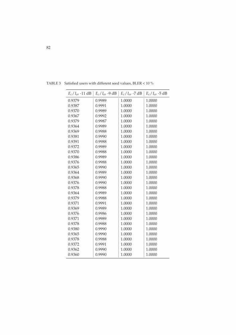
82
TABLE 3 Satisfied users with different seed values, BLER < 10 %
Ec/Ior -11 dB Ec/Ior -9 dB Ec/Ior -7 dB Ec/Ior -5 dB
0.9379 0.9989 1.0000 1.00000.9387 0.9991 1.0000 1.00000.9370 0.9989 1.0000 1.00000.9367 0.9992 1.0000 1.00000.9379 0.9987 1.0000 1.00000.9364 0.9989 1.0000 1.00000.9369 0.9988 1.0000 1.00000.9381 0.9990 1.0000 1.00000.9391 0.9988 1.0000 1.00000.9372 0.9989 1.0000 1.00000.9370 0.9988 1.0000 1.00000.9386 0.9989 1.0000 1.00000.9376 0.9988 1.0000 1.00000.9365 0.9990 1.0000 1.00000.9364 0.9989 1.0000 1.00000.9368 0.9990 1.0000 1.00000.9376 0.9990 1.0000 1.00000.9378 0.9988 1.0000 1.00000.9364 0.9989 1.0000 1.00000.9379 0.9988 1.0000 1.00000.9371 0.9991 1.0000 1.00000.9369 0.9989 1.0000 1.00000.9376 0.9986 1.0000 1.00000.9371 0.9989 1.0000 1.00000.9378 0.9988 1.0000 1.00000.9380 0.9990 1.0000 1.00000.9365 0.9990 1.0000 1.00000.9378 0.9988 1.0000 1.00000.9372 0.9991 1.0000 1.00000.9362 0.9990 1.0000 1.00000.9360 0.9990 1.0000 1.0000

83
TABLE 4 Satisfied users with different seed values, BLER < 1 %
Ec/Ior -11 dB Ec/Ior -9 dB Ec/Ior -7 dB Ec/Ior -5 dB
0.5526 0.8489 0.9797 0.99890.5510 0.8507 0.9815 0.99910.5516 0.8469 0.9796 0.99870.5513 0.8477 0.9783 0.99860.5526 0.8481 0.9797 0.99890.5519 0.8495 0.9816 0.99860.5538 0.8461 0.9797 0.99810.5518 0.8486 0.9800 0.99850.5507 0.8491 0.9807 0.99870.5529 0.8476 0.9794 0.99880.5518 0.8495 0.9813 0.99880.5538 0.8489 0.9813 0.99890.5496 0.8488 0.9806 0.99850.5512 0.8490 0.9805 0.99840.5519 0.8472 0.9797 0.99850.5507 0.8466 0.9817 0.99930.5504 0.8478 0.9795 0.99860.5523 0.8482 0.9794 0.99880.5518 0.8480 0.9797 0.99810.5530 0.8526 0.9804 0.99880.5501 0.8492 0.9791 0.99770.5522 0.8491 0.9799 0.99860.5497 0.8466 0.9796 0.99840.5503 0.8483 0.9796 0.99830.5531 0.8518 0.9804 0.99900.5552 0.8496 0.9811 0.99870.5529 0.8469 0.9802 0.99860.5528 0.8506 0.9807 0.99820.5493 0.8481 0.9800 0.99840.5525 0.8476 0.9797 0.99840.5501 0.8484 0.9806 0.9992

84
TABLE 5 Required Ec/Ior for 95 % coverage with different seeds
BLER < 1 % BLER < 4 % BLER < 10
-7.4544 -9.3358 -10.6024-7.4816 -9.3465 -10.6258-7.4466 -9.3343 -10.5808-7.4337 -9.3364 -10.5733-7.4518 -9.3400 -10.6012-7.4783 -9.3418 -10.5644-7.4449 -9.3430 -10.5778-7.4567 -9.3450 -10.6103-7.4670 -9.3417 -10.6341-7.4455 -9.3385 -10.5856-7.4750 -9.3425 -10.5802-7.4727 -9.3462 -10.6221-7.4638 -9.3337 -10.5946-7.4634 -9.3445 -10.5674-7.4486 -9.3416 -10.5644-7.4688 -9.3342 -10.5744-7.4483 -9.3458 -10.5958-7.4488 -9.3362 -10.5994-7.4512 -9.3345 -10.5644-7.4754 -9.3453 -10.6018-7.4476 -9.3406 -10.5845-7.4572 -9.3407 -10.5785-7.4454 -9.3482 -10.5933-7.4513 -9.3403 -10.5832-7.4723 -9.3425 -10.5994-7.4732 -9.3365 -10.6055-7.4528 -9.3414 -10.5674-7.4726 -9.3377 -10.5994-7.4547 -9.3391 -10.5868-7.4499 -9.3397 -10.5605-7.4625 -9.3422 -10.5559
TABLE 6 Statistical confidence for satisfied users, BLER < 10 %
Ec/Ior Ec/Ior Ec/Ior Ec/Ior
-11 dB -9 dB -7 dB -5 dB
MEAN 93.73 % 99.89 % 100.00 % 100.00 %STANDARD DEVIATION 0.0008 0.0001 0.0000 0.0000CONFIDENCE INTERVAL, 90 % ± 0.02 % ± 0.00 % ± 0.00 % ± 0.00 %CONFIDENCE INTERVAL, 95 % ± 0.03 % ± 0.00 % ± 0.00 % ± 0.00 %CONFIDENCE INTERVAL, 99 % ± 0.04 % ± 0.01 % ± 0.00 % ± 0.00 %

85
TABLE 7 Statistical confidence for satisfied users, BLER < 1 %
Ec/Ior Ec/Ior Ec/Ior Ec/Ior
-11 dB -9 dB -7 dB -5 dB
MEAN 55.18 % 84.86 % 98.02 % 99.86 %STANDARD DEVIATION 0.0014 0.0015 0.0008 0.0003CONFIDENCE INTERVAL, 90 % ± 0.07 % ± 0.05 % ± 0.02 % ± 0.01 %CONFIDENCE INTERVAL, 95 % ± 0.09 % ± 0.06 % ± 0.03 % ± 0.01 %CONFIDENCE INTERVAL, 99 % ± 0.12 % ± 0.08 % ± 0.04 % ± 0.02 %
TABLE 8 Statistical confidence for 95 % coverage level
BLER < 1 % BLER < 4 % BLER < 10 %
MEAN -7.4586 dB -9.3405 dB -10.5882 dBSTANDARD DEVIATION 0.0123 0.0040 0.0197CONFIDENCE INTERVAL, 90 % ± 0.05 % ± 0.01 % ± 0.06 %CONFIDENCE INTERVAL, 95 % ± 0.06 % ± 0.02 % ± 0.07 %CONFIDENCE INTERVAL, 99 % ± 0.08 % ± 0.02 % ± 0.09 %
TABLE 9 Main simulation parameters for statistical analysis of VoIP simulations
Simulation parameter Value(s)
Scenario Wrap-around, 21 hexagonal cellsCell radius 933 mChannel profile Vehicular APacket scheduling algorithm VoIP optimized proportional fairUE velocity 30 km/hHSDPA HO delay 200 msSID disabledAverage VoIP call length 40 sMinimum VoIP call length 20 sMaximum VoIP call length 60 sSimulation time 100, 200 and 400 s
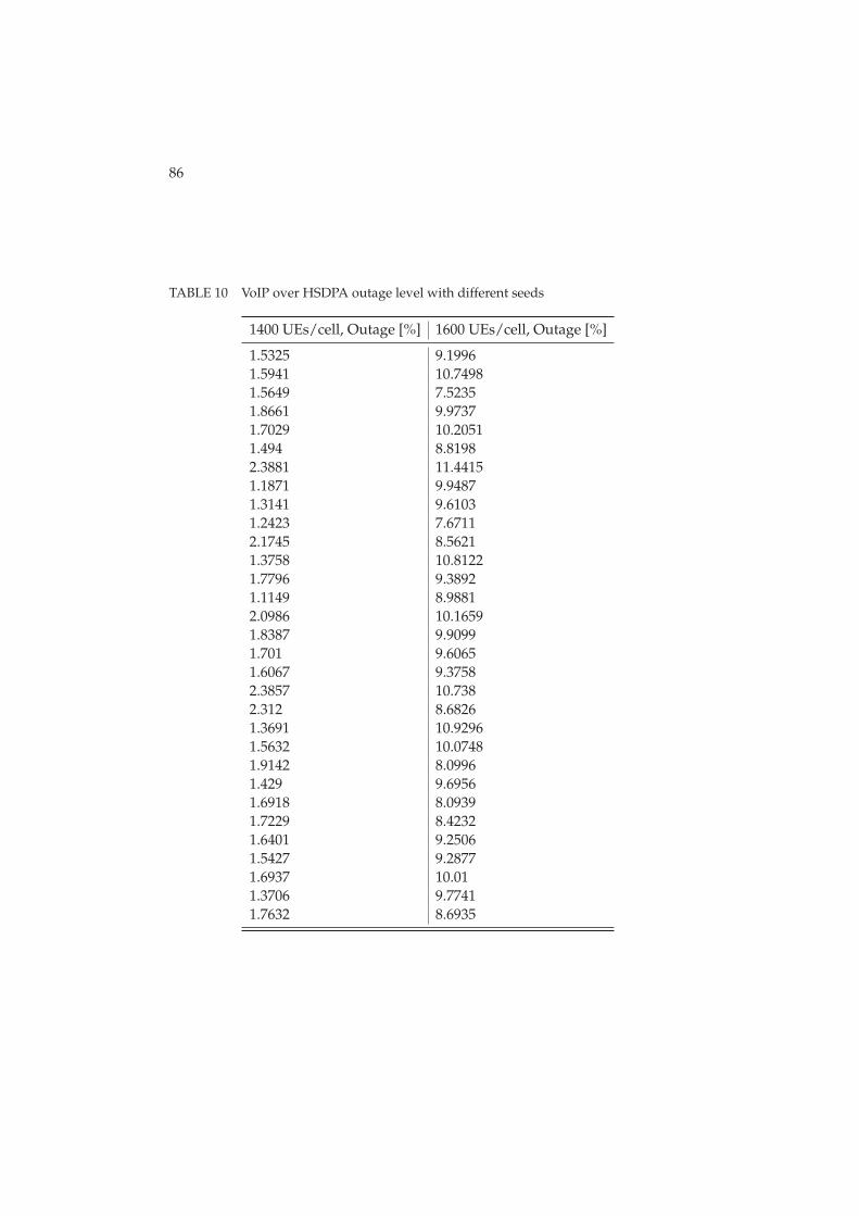
86
TABLE 10 VoIP over HSDPA outage level with different seeds
1400 UEs/cell, Outage [%] 1600 UEs/cell, Outage [%]
1.5325 9.19961.5941 10.74981.5649 7.52351.8661 9.97371.7029 10.20511.494 8.81982.3881 11.44151.1871 9.94871.3141 9.61031.2423 7.67112.1745 8.56211.3758 10.81221.7796 9.38921.1149 8.98812.0986 10.16591.8387 9.90991.701 9.60651.6067 9.37582.3857 10.7382.312 8.68261.3691 10.92961.5632 10.07481.9142 8.09961.429 9.69561.6918 8.09391.7229 8.42321.6401 9.25061.5427 9.28771.6937 10.011.3706 9.77411.7632 8.6935

87
TABLE 11 VoIP over HSDPA 95 % outage level with different seeds
Capacity [users/cell] Capacity [users/cell]
70.9739 70.209572.1570 70.348070.3599 71.224569.4125 70.811370.8869 72.233570.8794 70.324570.6972 71.366370.0919 70.396970.6410 70.826469.6476 70.685270.2836 70.512271.4179 70.780871.5880 71.324870.8713 70.918070.4530 70.779971.1148
TABLE 12 VoIP over HSDPA 95 % outage level with different simulation lengths
Simtime 0.5x Simtime 1x Simtime 2x
70.9647 70.9739 69.9607

88
TABLE 13 Statistical confidence for VoIP over HSDPA outage level
1400 UEs/cell, 1600 UEs/cell,Outage [%] Outage [%]
MEAN 1.68 9.47STANDARD DEVIATION 0.33191 0.97242CONFIDENCE INTERVAL, 90 % ± 5.85 % ± 3.03 %CONFIDENCE INTERVAL, 95 % ± 6.97 % ± 3.61 %CONFIDENCE INTERVAL, 99 % ± 9.16 % ± 4.75 %
TABLE 14 Statistical confidence for 95 % VoIP over HSDPA outage level
Capacity [UEs/cell]
MEAN 70.78122STANDARD DEVIATION 0.612021CONFIDENCE INTERVAL, 90 % ± 0.25 %CONFIDENCE INTERVAL, 95 % ± 0.30 %CONFIDENCE INTERVAL, 99 % ± 0.40 %
presented above are gathered to Tables 13 and 14. As those tables show abnormal-ities are very minimal especially when interpolated capacity numbers are consid-ered. Thus, this leads us to believe that VoIP results presented in this thesis arereliable.
APPENDIX 2 SIMULATION PARAMETERS
The purpose of this appendix is to present briefly main simulation parametersfor MBMS and VoIP studies. Table 15 presents simulation parameters for MBMSsimulations. Table 16 sums up common VoIP parameters used for VoIP studiesand Tables 18 and 17 present HSDPA and HSUPA assumptions, respectively.
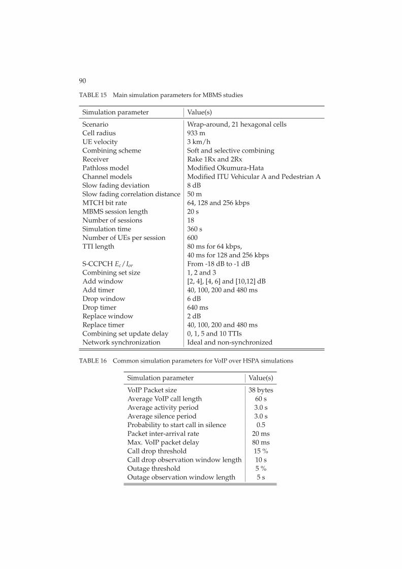
90
TABLE 15 Main simulation parameters for MBMS studies
Simulation parameter Value(s)
Scenario Wrap-around, 21 hexagonal cellsCell radius 933 mUE velocity 3 km/hCombining scheme Soft and selective combiningReceiver Rake 1Rx and 2RxPathloss model Modified Okumura-HataChannel models Modified ITU Vehicular A and Pedestrian ASlow fading deviation 8 dBSlow fading correlation distance 50 mMTCH bit rate 64, 128 and 256 kbpsMBMS session length 20 sNumber of sessions 18Simulation time 360 sNumber of UEs per session 600TTI length 80 ms for 64 kbps,
40 ms for 128 and 256 kbpsS-CCPCH Ec/Ior From -18 dB to -1 dBCombining set size 1, 2 and 3Add window [2, 4], [4, 6] and [10,12] dBAdd timer 40, 100, 200 and 480 msDrop window 6 dBDrop timer 640 msReplace window 2 dBReplace timer 40, 100, 200 and 480 msCombining set update delay 0, 1, 5 and 10 TTIsNetwork synchronization Ideal and non-synchronized
TABLE 16 Common simulation parameters for VoIP over HSPA simulations
Simulation parameter Value(s)
VoIP Packet size 38 bytesAverage VoIP call length 60 sAverage activity period 3.0 sAverage silence period 3.0 sProbability to start call in silence 0.5Packet inter-arrival rate 20 msMax. VoIP packet delay 80 msCall drop threshold 15 %Call drop observation window length 10 sOutage threshold 5 %Outage observation window length 5 s
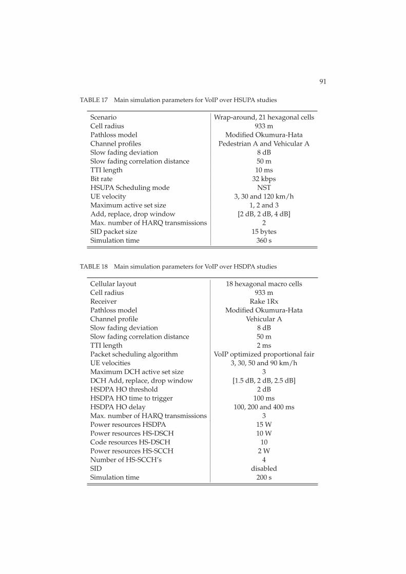
91
TABLE 17 Main simulation parameters for VoIP over HSUPA studies
Scenario Wrap-around, 21 hexagonal cellsCell radius 933 mPathloss model Modified Okumura-HataChannel profiles Pedestrian A and Vehicular ASlow fading deviation 8 dBSlow fading correlation distance 50 mTTI length 10 msBit rate 32 kbpsHSUPA Scheduling mode NSTUE velocity 3, 30 and 120 km/hMaximum active set size 1, 2 and 3Add, replace, drop window [2 dB, 2 dB, 4 dB]Max. number of HARQ transmissions 2SID packet size 15 bytesSimulation time 360 s
TABLE 18 Main simulation parameters for VoIP over HSDPA studies
Cellular layout 18 hexagonal macro cellsCell radius 933 mReceiver Rake 1RxPathloss model Modified Okumura-HataChannel profile Vehicular ASlow fading deviation 8 dBSlow fading correlation distance 50 mTTI length 2 msPacket scheduling algorithm VoIP optimized proportional fairUE velocities 3, 30, 50 and 90 km/hMaximum DCH active set size 3DCH Add, replace, drop window [1.5 dB, 2 dB, 2.5 dB]HSDPA HO threshold 2 dBHSDPA HO time to trigger 100 msHSDPA HO delay 100, 200 and 400 msMax. number of HARQ transmissions 3Power resources HSDPA 15 WPower resources HS-DSCH 10 WCode resources HS-DSCH 10Power resources HS-SCCH 2 WNumber of HS-SCCH’s 4SID disabledSimulation time 200 s
REFERENCES
[1] 3GPP, http://www.3gpp.org/, Cited June 2008.
[2] 3GPP, Requirements for Evolved UTRA (E-UTRA) and Evolved UTRAN (E-
UTRAN), Technical Requirement, TR 25.913, Release 7, March 2006.
[3] 3GPP, Broadcast/Multicast Control BMC, Technical Specification, TS25.324, Release 6, June 2006.
[4] 3GPP, Technical Realization of Cell Broadcast Service (CBS), Technical Spec-ification, TS 23.041, Release 6, January 2004.
[5] 3GPP, General Packet Radio Service (GPRS); Service description; Stage 1,Technical Specification, TS 22.060, March 2003.
[6] 3GPP, General Packet Radio Service (GPRS); Service description; Stage 2,Technical Specification, TS 23.060, Release 6, October 2006.
[7] 3GPP, Multimedia Broadcast Multicast Service (MBMS) Stage 1., TechnicalSpecification, TS 22.146, Release 6, March 2006.
[8] 3GPP, MBMS Architecture and Functional Description, Technical Specifica-tion, TS 23.246, Release 6, June 2006.
[9] 3GPP, Multimedia Broadcast Multicast Service (MBMS); UTRAN/GERAN
Requirements, Technical Requirement, TR 25.992, October 2003.
[10] 3GPP, Introduction of the Multimedia Broadcast Multicast Service (MBMS)
in the Radio Access Network (RAN); Stage 2, Technical Specification, TS25.346, Release 6, June 2006.
[11] 3GPP, Technical Specification Group Services and System Aspects; IP Multime-
dia Subsystem (IMS); Stage 2, Technical Specification, TS 23.228, December2008.
[12] 3GPP, Technical Specification Group Services and System Aspects; Speech
Codec Speech Processing Functions; Adaptive Multi-Rate - Wideband (AMR-
WB) Speech Codec; General Description, Technical Specification, TS 26.171,December 2008.
[13] 3GPP, Selection Procedures for the Choice of Radio Transmission Technologies
of the UMTS Technical Requirement, TR 101 112 (UMTS 30.03), April1998.
[14] A. Alexiou, C. Bouras, V. Kokkinos and E. Rekkas, Power Efficient Radio
Bearer Selection in MBMS Multicast Mode, In Proceedings of ACM Inter-national Symposium on Modeling, Analysis and Simulation of Wirelessand Mobile Systems, Chania, Crete Island, Greece, October 2007.

93
[15] E. Biglieri, J. Proakis and S. Shamai, Fading Channels; Information-theoretic
and Communications Aspects, IEEE Transactions on Information Theory,October 1998.
[16] T. Chen, M. Kuusela, and E. Malkamäki, Uplink Capacity of VoIP on
HSUPA, In Proceedings of IEEE 63rd Vehicular Technology Conference,Melbourne, Australia, May 2006.
[17] M. Chuah, T. Hu and W. Luo, UMTS Release 99/4 Airlink Enhancement for
Supporting MBMS Services, In Proceedings of IEEE International Confer-ence on Communications, Paris, France, June 2004.
[18] Cisco, Echo Analysis for Voice over IP, http://www.cisco.com/en/US/docs/ios/solutions_docs/voip_solutions/EA_ISD.pdf,November 2002.
[19] A. Correia, J. Silva, N. Souto, L. Silva, A. Boal and A. Soares, Multi-
Resolution Broadcast/Multicast Systems for MBMS, IEEE Transactions onBroadcasting, vol 53, no. 1, March 2007.
[20] E. Dahlman, S. Parkvall, J. Sköld and P. Beming, 3G Evolution - HSPA and
LTE for Mobile Broadband, 1st edition, Elsevier Ltd., 2007.
[21] E. Damosso and L. M. Correia (editors), Digital Mobile Radio Towards Fu-
ture Generation Systems, Technical report, COST 231 Final report, 1999.
[22] Ericsson, Introduction to IMS, White paper, http://www.ericsson.com/technology/whitepapers/8123_Intro_to_ims_a.pdf,March 2007.
[23] F. Hartung, U. Horn, J. Huschke, M. Kampmann, T. Lohmar and M. Lun-devall, Delivery of Broadcast Services in 3G Networks, IEEE Transactions onBroadcasting, vol. 53, no. 1, March 2007.
[24] M. Hata, Empirical Formula for Propagation Loss in Land mobile Radio Ser-
vices IEEE Transactions on Vehicular Technology, August 1980.
[25] H. Holma, M. Kuusela, E. Malkamäki, K. Ranta-aho, and T. Chen, VoIP
over HSPA with 3GPP release 7, In Proceedings of IEEE InternationalSymposium on Personal, Indoor and Mobile Radio Communications(PIMRC), Helsinki, Finland, September 2006.
[26] H. Holma and A. Toskala, WCDMA for UMTS: Radio Access for Third Gen-
eration Mobile Communications, 4th edition. John Wiley & Sons Ltd, 2007.
[27] H. Holma and A. Toskala, HSDPA/HSUPA for UMTS, 1st edition, JohnWiley & Sons Ltd, 2006.
[28] A. Hottinen, O. Tirkkonen and R. Wichman, Multi-Antenna Transceiver
Techniques for 3G and Beyond, John Wiley & Sons Ltd, 2003.
94
[29] A. Hottinen, O. Tirkkonen and R. Wichman, Multi-Antenna Transceiver
Techniques for 3G and Beyond, John Wiley & Sons, Ltd, 2003.
[30] S. Hämäläinen, WCDMA Radio Network Performance, Doctoral thesis,University of Jyväskylä, 2003.
[31] S. Hämäläinen, H. Holma and K. Sipilä, Advanced WCDMA Radio Net-
work Simulator, In Proceedings of IEEE International Symposium onPersonal, Indoor and Mobile Radio Communications (PIMRC), Osaka,Japan, September 1999.
[32] S. Hämäläinen, P. Slanina, M. Hartman, A. Leppeteläinen, H. Holma andO. Salonaho A Novel Interface Between Link and System Simulations, In Pro-ceedings of ACTS Summit, Aalborg, Denmark, October 1997.
[33] IETF, SIP: Session Initiation Protocol, RFC 3261, June 2002.
[34] IETF, SDP: Session Description Protocol, RFC 2327, April 1998.
[35] IETF, RTP: A Transport Protocol for Real-Time Applications, RFC 3550, July2003.
[36] IETF, RTP Payload Format for MPEG1/MPEG2 Video, RFC 2250, January1998.
[37] IETF, RTP Payload Format for MPEG-4 Audio/Visual Streams, RFC 3016,November 2000.
[38] IETF, RTP Payload for Text Conversation, RFC 4103, June 2005.
[39] IETF, Compressing IP/UDP/RTP Headers for Low-Speed Serial Links, RFC2508, February 1999.
[40] IETF, RObust Header Compression (ROHC): Framework and Four Profiles:
RTP, UDP, ESP, and Uncompressed, RFC 3095, July 2001.
[41] ITU-T, Series G: Transmission Systems and Media, Digital Systems and Net-
works: International Telephone Connections and circuits - General Recommen-
dations on the transmission quality for an entire international telephone con-
nection, Recommendation G.114, May 2003.
[42] J. Kurjenniemi, A Study of TD-CDMA and WCDMA Radio Network En-
hancements, Doctoral thesis, University of Jyväskylä, 2005.
[43] M. Luby, T. Gasiba, T. Stockhammer and M. Watson, Reliable Multimedia
Download Delivery in Cellular Broadcast Networks, IEEE Transactions onBroadcasting, vol 53, no. 1, March 2007.
[44] P. Lunden, and M. Kuusela, Enhancing Performance of VoIP over HSDPA,In Proceedings of 65th IEEE Vehicular Technology Conference, Dublin,Ireland, April 2007.

95
[45] T.Nihtilä, Performance of Advanced Transmission and Reception Algorithms
for High Speed Downlink Packet Access, Doctoral thesis, ISBN 978-951-39-3236-7, University of Jyväskylä, 2008.
[46] Y. Okumura, E. Ohmori, T. Kawano and K. Fukuda, Field Strength and Its
Variability in VHF and UHF Land-mobile Service, Review of the ElectricalCommunication Laboratory, 1968.
[47] R. Price and P. E. Green Jr., A Communication Technique for Multipath Chan-
nels, In Proceedings of the IRE, pages 555 - 570, March 1958.
[48] J. G. Proakism, Digital Communications, McGraw-Hill, 1995.
[49] F. Rui, F. Persson, M. Nordberg, S. Wanstedt, M. Qingyu, and G. Xinyu,Coverage Study for VoIP over Enhanced Uplink, In Proceedings of IEEE 63rdVehicular Technology Conference, Melbourne, Australia, May 2006.
[50] J. S. Seybold, Introduction to RF Propagation, John Wiley & Sons, Ltd, 2005.
[51] A. Soares, A. Correia, J. Silva and N. Souto, UE Counting Mechanism for
MBMS Considering PtM Macro Diversity Combining Support in UMTS Net-
works, In Proceedings of IEEE 9th International Symposium on SpreadSpectrum Techniques and Applications, August 2006.
[52] S. M. Sussman, A Matched Filter Communication System for Multipath
Channels, IEEE Transactions on Information Theory, pages: 367 - 373,June 1960.
[53] G. L. Turin, Introduction to Spread-spectrum Antimultipath Techniques and
Their Applications to Urban Digital Radio, In Proceedings of the IEEE,March 1980.
[54] A. J. Viterbi, CDMA: Principles of Spread Spectrum Communication,Addison-Wesley Wireless Communications Series, 1995.
[55] S. Wager, and K. Sandlund, Performance Evaluation of HSDPA Mobility for
Voice over IP, In Proceedings of 65th IEEE Vehicular Technology Confer-ence, Dublin, Ireland, April 2007.
[56] B. Wang, K. I. Pedersen, T. E. Kolding, and P. E. Mogensen, Performance of
VoIP on HSDPA, In Proceedings of 61st IEEE Vehicular Technology Con-ference, Stockholm, Sweden, May 2005.
[57] J. Wigard, M. Boussif, N. H. Madsen, M. Brix, S. Corneliussen, and E.A. Laursen, High Speed Uplink Packet Access Evaluation by Dynamic Net-
work Simulations, In Proceedings of IEEE International Symposium onPersonal, Indoor and Mobile Radio Communications (PIMRC), Helsinki,Finland, September 2006.
[58] Wireless Intelligence, https://www.wirelessintelligence.com/, cited March2009.