al-fec for streaming services in lte e-mbms
TRANSCRIPT

8/10/2019 AL-FEC for Streaming Services in LTE E-MBMS
http://slidepdf.com/reader/full/al-fec-for-streaming-services-in-lte-e-mbms 1/12
R E S E A R C H Open Access
AL-FEC for streaming services in LTE E-MBMSJorge Calabuig, Jose F Monserrat*, David Gozálvez and David Gómez-Barquero
Abstract
3rd Generation Partnership Project specified Application Layer - Forward Error Correction (AL-FEC) to be used for
Enhanced Multimedia Broadcast Multicast Services (E-MBMS) in Long Term Evolution (LTE) networks. Specifically,
Raptor coding is applied to both streaming and file delivery services. This article focuses on streaming services and
investigates the optimum configuration of the AL-FEC mechanism depending on the signal-to-interference plus
noise power ratio conditions. These configurations are compared with a scenario without an application layer
protection to obtain the potential gain that can be achieved by means of AL-FEC. This article also studies the
multiplexing of services within the AL-FEC time interleaving. These analyses were performed using a proprietary
system level simulator and assuming both pedestrian and vehicular users. Different quality criterions were used to
ensure the completeness of the study. Results show the significant benefit of using AL-FEC in E-MBMS in terms of
coverage and service quality.
Keywords: LTE, E-MBMS, Raptor codes, AL-FEC, Broadcast, Streaming
1. IntroductionUniversal mobile telecommunications systems (UMTS)
integrated in March 2005—Release 6—Multimedia Broad-
cast Multicast Services (MBMS) as a technical feature to
provide an efficient delivery mode of mass multimedia
services such as mobile TV [1]. Since these services are
designed to be simultaneously broadcasted to a largenumber of users, MBMS introduced new point-to
-multipoint (p-t-m) radio bearers and multicast support in
the core network. The main benefit of p-t-m bearers is the
efficient usage of physical resources. Per contra, p-t-m
bearers cannot adapt modulation and coding schemes for
each individual user. This can result in high loss rates for
users with poor channel conditions [2].
To overcome these problems and increase the robust-
ness of the p-t-m transmissions, MBMS introduced an
additional forward error correction (FEC) mechanism at
the application layer (AL-FEC) based on Raptor codes
for both streaming and file delivery services [3]. Raptorcodes are a computationally efficient implementation of
fountain codes that achieve close to ideal performance.
This permits a software implementation without the
need of dedicated hardware even in handheld devices
[4]. By working at the application layer, it is possible to
recover packet losses of all underlying layers and proto-
cols, providing end-to-end error correction without any
required change in legacy standards.
In Release 7, the 3rd Generation Partnership Project
(3GPP) standardized the use of MBMS over a Single Fre-
quency Network (MBSFN), which boosts performance
[5]. In a SFN, multiple base stations are synchronizedand transmit the same information to the receivers. This
improves signal quality reception and hence efficiency.
Later on, the 3GPP initiated the Long Term Evolution
(LTE) standardization activity to enhance UMTS, thanks
to the usage of Orthogonal Frequency Division Multiple
Access (OFDMA) modulation [6]. The first version of
LTE—Release 8—was completed in December 2008. LTE
comprised from the beginning the MBMS feature,
renamed as Enhanced MBMS (E-MBMS), whose defin-
ition in Release 8 only included physical channels [7]. It
was not until Release 9—issued at the end of 2009—
when higher layer aspects were specified [8]. E-MBMSincludes again SFN and AL-FEC mechanisms and adds
new features inherited from other successful broadcast
networks, such as the use of extended cyclic prefix (CP).
To this date, MBMS has been incorporated to a very
limited number of commercial networks. However, with
the better system performance and the higher flexibility
provided by LTE, E-MBMS has regained interest [9,10].* Correspondence: [email protected]
iTEAM Research Institute, Universitat Politècnica de València, Camino de Vera
S/N, 46022, Valencia, Spain
© 2013 Calabuig et al.; licensee Springer. This is an Open Access article distributed under the terms of the Creative CommonsAttribution License (http://creativecommons.org/licenses/by/2.0), which permits unrestricted use, distribution, and reproductionin any medium, provided the original work is properly cited.
Calabuig et al. EURASIP Journal on Wireless Communications and Networking 2013, 2013:73
http://jwcn.eurasipjournals.com/content/2013/1/73

8/10/2019 AL-FEC for Streaming Services in LTE E-MBMS
http://slidepdf.com/reader/full/al-fec-for-streaming-services-in-lte-e-mbms 2/12
Concerning the application of AL-FEC protection for
broadcast and multicast services over wireless mobile
networks, this topic has extensively been studied in 3rd
Generation (3G) including file delivery [11-13] and
streaming services [13,14]. These works analyzed the
system trade-offs between AL-FEC and PHY-FEC for
MBMS and concluded that only a well-designed system
that combines both coders can maximize efficiency and
user perception. The results also pointed out that the re-
lationship between encoding rates defined in MBMS is
not the optimal. It would be beneficial to reduce the
protection at the physical layer and increase Raptor code
protection. However, the protection period must be
taken into account in case of streaming services to guar-
antee small zapping times, which is defined as the time
elapsed since the viewer presses the channel change but-
ton until the new channel is displayed.
Regarding LTE and the application of AL-FEC in E-MBMS, Alexiou et al. [15] presented a cost analysis that
compares the performance of a new error recovery scheme
based on Raptor codes with other existing approaches
under different MBSFN deployments, user populations,
and error rates. This study only focused on the file delivery
service. Concerning streaming services, Munaretto et al.
[16] analyzed a cross-layer framework aimed at optimizing
the number of streamed video layers, the modulation and
coding scheme (MCS), and the application layer FEC used
for each layer. Bouras et al. [17] also studied the use of AL-
FEC over E-MBMS streaming services. Assuming a single-
cell scenario, they investigated how the FEC overhead canbe reduced under different packet loss conditions. Despite
these two seminal works, the potential gain that can be
achieved using AL-FEC mechanisms in E-MBMS has not
been addressed in a holistic manner.
Note that all these works considered the 3GPP standard-
ized Raptor coding [3]. However, there exists a new gener-
ation of fountain codes called RaptorQ [18]. This code
minimizes the redundant FEC information outperforming
Raptor code. Per contra, the improved coding performance
comes at the expense of increased encoding and decoding
complexity. Mladenov et al. [19] investigated the applica-
tion of RaptorQ in MBMS services and compared Raptor
and RaptorQ codes. They concluded that although theRaptorQ code has better coding properties, it is too com-
plex for efficient real-time decoding in MBMS terminals.
This article evaluates the benefits of AL-FEC in
streaming services over LTE MBSFN networks and
provides guidelines for the efficient transmission of E-
MBMS services. Consequently, this study addresses sim-
ultaneously the radio resource management (RRM)
problem [20] and the trade-off between PHY-FEC and
AL-FEC. The main goal is to obtain the best configura-
tions that allow the highest E-MBMS service data rate
when a fixed amount of resources is allocated for E-
MBMS. On the other hand, this article also studies how
the conditions of the scenario in terms of signal-to-inter-
ference plus noise power ratio (SINR) affect the selection
of PHY-FEC and AL-FEC parameters. Finally, different al-
ternatives of E-MBMS scheduling are evaluated to deter-
mine how different services must be multiplexed within the
AL-FEC interleaving time. Extensive simulations have been
carried out using a proprietary LTE-compliant system level
simulator that has been extended to assess AL-FEC protec-
tion. It is worth noting that the simulation tool was cali-
brated against 3GPP and International Telecommunication
Union Radiocommunication Sector (ITU-R) reports.
The remainder of this article is organized as follows:
Section 2 describes the main features of E-MBMS in-
cluded in the 3GPP LTE standard. Section 3 presents the
FEC techniques used in E-MBMS. Section 4 describes
the simulation environment and assumptions. Finally,
simulation results are discussed in Section 5, whereasSection 6 draws the main conclusions of the article.
2. E-MBMS technical featuresLTE E-MBMS includes some features previously used in
3G MBMS, such as MBSFN operation and AL-FEC, but
E-MBMS also incorporates other new mechanisms. This
section addresses these new features.
2.1. Physical layer features
In MBSFN operation, a cluster of time-synchronized
cells transmits the same E-MBMS content. These cellsform an MBSFN area and, in order to preserve orthog-
onality, signals from the MBSFN cells must reach the
users within the CP. Otherwise, the signal produces
inter-symbol interference. In order to allow larger cluster
sizes, the LTE standard increases the CP from 4.6 μs—
normal CP—to 16.7 μs—extended CP—for the MBSFN
physical channel, the physical multicast channel (PMCH)
[7]. Moreover, an optional double CP length of around
33 μs can be used in scenarios with large inter-site dis-
tances (ISDs). In order to avoid an increase in overhead
due to the double-sized CP, the number of subcarriers is
also doubled by defining a subcarrier spacing of 7.5 kHz
instead of 15 kHz, only for MBMS-dedicated cells. How-ever, this dedicated carrier deployment is still not sup-
ported in current releases of LTE and E-MBMS services
must share resources with unicast users [8].
On the other hand, in E-MBMS the transmission time
interval (TTI), which fixes the amount of information to
be coded by the PHY-FEC mechanism, is 1 ms. In this
way, time interleaving at the E-MBMS physical layer is
much lower than in the case of 3G MBMS, with TTIs
from 10 up to 80 ms. However, the OFDMA modulation
used in LTE enables frequency diversity at the receiver,
which is not present at the physical layer of 3G MBMS.
Calabuig et al. EURASIP Journal on Wireless Communications and Networking 2013, 2013:73 Page 2 of 12
http://jwcn.eurasipjournals.com/content/2013/1/73

8/10/2019 AL-FEC for Streaming Services in LTE E-MBMS
http://slidepdf.com/reader/full/al-fec-for-streaming-services-in-lte-e-mbms 3/12
2.2. E-MBMS scheduling
Whereas 3G MBMS services are multiplexed with
unicast services using different channelization codes,
LTE E-MBMS services are multiplexed in time inside
MBSFN subframes. Therefore, some E-MBMS control
information must be used in order to inform users about
E-MBMS scheduling [21]. The logical channels that
carry information of E-MBMS services are the multicast
control channel (MCCH) and the multicast traffic chan-
nel (MTCH). Traffic data of E-MBMS services are trans-
mitted using an MTCH, while MCCH carries control
information associated to all MTCHs transmitted in a
MBSFN area. Both MTCH and MCCH are mapped into
the multicast transport channel (MCH). Finally, the
MCH transport channel is mapped into the PMCH.
The eNodeB transmits System Information Blocks
(SIBs) through the broadcast control channel (BCCH)
[22]. There are two SIBs related to E-MBMS: SIB2 and
SIB13. SIB2 informs the user about which subframes are
reserved for MBSFN. On the other hand, SIB13 indicates
how many MBSFN areas are configured in a cell and
which are the subframes and the MCS used by the
MCCH of each MBSFN area. MCCHs are periodically
transmitted over one of the MBSFN-capable subframes,
being this period broadcasted over the SIB13. It is im-
portant to note that among the 10 subframes included
Subframes reserved for unicast
1 Radio frame (10 ms)
MBSFN subframes
C S A p e r i o d ( 1 6 0 m s )
SFN
0
MCH 2
MCH 1
1
2
3
4
5
6
7
8
9
10
1112
13
14
15
MSI 1
MTCH 1
MCCH
MTCH 1
MTCH 1
MTCH 1
MTCH 1
MTCH 1
MTCH 1
MTCH 1
MTCH 1
MTCH 2
MSI 2 MTCH 3
MTCH 1
MTCH 1
MTCH 1
MTCH 1
MTCH 1
MTCH 1
MTCH 1
MTCH 1
MTCH 1
MTCH 1
MTCH 2 MTCH 2
MTCH 2 MTCH 2
MTCH 2 MTCH 2
MTCH 2 MTCH 2
MTCH 2 MTCH 2
MTCH 2 MTCH 2
MTCH 2 MTCH 2
MTCH 2 MTCH 2
MTCH 2 MTCH 2
MTCH 3 MTCH 3
MTCH 3 MTCH 3MTCH 3 MTCH 3
MTCH 3 MTCH 3
MTCH 3 MTCH 3
MTCH 3 MTCH 3
MTCH 3 MTCH 3
MTCH 3 MTCH 3
MTCH 3 MTCH 3
MTCH 3 MTCH 3MTCH 3 MTCH 3
16
17
18
19
20
21
23
24
25
26
2728
29
30
31
32
MSI 1
MTCH 1
MTCH 1
MTCH 1
MTCH 1
MTCH 1
MTCH 1
MTCH 1
MTCH 1
MTCH 1
MTCH 1
MTCH 2
MTCH 1
MTCH 1
MTCH 1
MTCH 1
MTCH 1
MTCH 1
MTCH 1
MTCH 1
MTCH 1
MTCH 1
MTCH 2 MTCH 2
MTCH 2 MTCH 2
MTCH 2 MTCH 2
MTCH 2 MTCH 2
MTCH 2 MTCH 2
MTCH 2 MTCH 2
MTCH 2 MTCH 2
MTCH 2 MTCH 2
MTCH 2 MTCH 2
MTCH 4 MTCH 4MTCH 4 MTCH 4
MTCH 4 MTCH 4
MTCH 4 MTCH 4
MTCH 4 MTCH 4
MTCH 4 MTCH 4
MTCH 4 MTCH 4MTCH 4 MTCH 4
MTCH 4 MTCH 4
MTCH 4 MTCH 4
MTCH 4 MTCH 4
MTCH 4 MTCH 4
33
34
MSI 1
MTCH 1
MTCH 1
MTCH 1
MTCH 1
MTCH 1
MTCH 1
MTCH 1
... ... ... ... ... ... ... ... ... ...
35 MCCH MTCH 1 MTCH 1 MTCH 1
43
44
MSI 2 MTCH 3 MTCH 3 MTCH 3
MTCH 3 MTCH 3MTCH 3 MTCH 3
... ... ... ... ... ... ... ... ... ...
M C C H r e p e t i t i o n p e r i o d ( 3 2 0 m s ) M
S P 1
( 1 6 0 m s )
M S P 2 ( 3 2 0 m s )
# 0 # 1 # 2 # 3 # 4 # 5 # 6 # 7 # 8 # 9
Figure 1 E-MBMS scheduling parameters.
Calabuig et al. EURASIP Journal on Wireless Communications and Networking 2013, 2013:73 Page 3 of 12
http://jwcn.eurasipjournals.com/content/2013/1/73

8/10/2019 AL-FEC for Streaming Services in LTE E-MBMS
http://slidepdf.com/reader/full/al-fec-for-streaming-services-in-lte-e-mbms 4/12
in a radio frame, the maximum number of MBSFN sub-
frames is six, since subframes #0, #4, #5, and #9 are re-
served for unicast transmission.
The MCCH informs about the scheduling of the
PMCHs within the MBSFN subframes related to this
MBSFN area through the Common Subframe Allocation
(CSA) and the PMCH-InfoList. The former indicates
which subframes are reserved for all the MCHs of an
MBSFN area, while the latter indicates how the sub-
frames are shared among those MCHs. Besides, PMCH-
InfoList reports the MCS of the E-MBMS services
related to each MCH. Finally, each MCH can multiplex
several E-MBMS services. In order to identify the specific
E-MBMS service, the PMCH-InfoList defines all the E-
MBMS ongoing sessions (identified by MTCH). Moreover,
the PMCH-InfoList indicates a period of time known as
MCH Scheduling Period (MSP) where the associated
MTCHs are multiplexed. This MTCH multiplexing is in-dicated in the first subframe of each MSP by means of a
medium access control (MAC) control element called
MCH Scheduling Information (MSI).
In order to clarify E-MBMS scheduling, Figure 1
shows an example of E-MBMS configuration. Four sub-
frames are assigned to E-MBMS: #1, #2, #6, and #7. The
repetition period of the MCCH is 320 ms. The CSA
period where two different MCH are scheduled is 160
ms. Each MCH has two E-MBMS services: MTCH 1
and MTCH 2 correspond to MCH 1 while MTCH 3 and
MTCH 4 correspond to MCH 2. The MSPs are 160 and
320 ms for MCH 1 and MCH 2, respectively. Note thatSFN in Figure 1 means system frame number.
3. FEC techniques in E-MBMSAs any communication system, LTE also employs FEC
techniques. FEC mechanisms rely on the transmission of
repair information to protect from packet losses in
underlying levels without a need for feedback, in such a
way that the receiver can detect and possibly correct er-
rors occurred during transmission. In particular, LTE
uses Turbo codes as the FEC mechanism that works at
the physical layer and, for broadcast and multicast trans-
missions, LTE can use Raptor codes at the application
layer [3].LTE standard defines Turbo codes as the physical layer
FEC to protect data against errors in the transmission
over unreliable or noisy communication channels, such
as mobile wireless channel. One of the main benefits of
the use of turbo codes is that they can exploit channel
state information using soft decision decoding, thus
achieving a high-performance. However, in practice, due
to on-chip memory and decoding complexity con-
straints, the maximum time interleaving depth is rather
small. In LTE E-MBMS transmissions, this maximum
time interleaving depth depends on the TTI or subframe
length, which is only 1 ms [7]. As a consequence, PHY-
FEC is often combined with an AL-FEC code, thus
achieving a better trade-off between overall system error
protection and complexity of the implementation. By
working at the application layer, it is possible to provide
protection against longer losses with larger interleaving
depths. However, the system FEC configuration must be
optimized taking into account this cross-layer operation.
Figure 2 shows the protocol stack of E-MBMS includ-
ing AL-FEC protection for the specific case of streaming
services. AL-FEC coding is performed over Real-time
Transport Protocol (RTP) packets. In video streaming
applications, these RTP packets generally include H.264
Network Abstraction Layer (NAL) units and/or audio
packets. In order to fit to the Maximum Transmission
Unit (MTU) of the Internet Protocol (IP) layer, the NAL
units might be fragmented.
The application of AL-FEC to streaming media inMBMS is described in [3]. As depicted in Figure 2, three
parameters have to be defined with regards to Raptor
encoding: the protection period (T pp), the code rate
(k/n) and the source symbol size (T ) measured in bytes.
The code rate (CR) determines the amount of erroneous
symbols than can be corrected at the application layer.
Lower CRs increase not only the protection of AL-FEC,
but also the amount of overhead that must be transmit-
ted in the form of parity packets. On the other hand, T pp
determines the period of time over which the source
blocks are transmitted. Longer protection periods imply
higher time diversity and hence offer better robustnessbut at the cost of increasing the end-to-end delay and
zapping time experimented by the user. This zapping
time has a significant impact on the quality-of-service
(QoS) perceived by the users. In order to reduce zapping
time, several fast zapping techniques can be applied [3].
However, it must be noted that long protection periods
greater than 10 s are not feasible in practice for stream-
ing services, as they will involve long zapping times that
Streaming Application
Streaming Codecs
RTP Payload Formats
SRTP
AL-FEC
RTP/RTCP
UDP
IP
RLC
MAC
PHY
FEC Source block
k
T
n-k
S o u r c e
s y m b o l s
R e p a i r
s y m b o l s
...
RTP packets
Tpp
PHY-FEC
Figure 2 E-MBMS protocol stack for streaming services (left)
and an example of FEC source block (right).
Calabuig et al. EURASIP Journal on Wireless Communications and Networking 2013, 2013:73 Page 4 of 12
http://jwcn.eurasipjournals.com/content/2013/1/73

8/10/2019 AL-FEC for Streaming Services in LTE E-MBMS
http://slidepdf.com/reader/full/al-fec-for-streaming-services-in-lte-e-mbms 5/12
would be difficult to tolerate by the users even with fast
zapping techniques [23].The Raptor coding process is based on a systematic
Raptor encoder, which uses a source block of k source
symbols to generate the repair symbols. Then, first of all,
a FEC source block is constructed from a set of RTP
packets, exactly those generated in a T pp. The size of the
FEC source block is k times T , where k is the number of
source symbols (which also depends on the T pp). The se-
lection of T pp depends mainly on the desired delay and
the memory available in the device. Therefore, all
packets included in a single FEC source block are jointly
protected. Afterwards, the Raptor encoder generates n −
k repair symbols of size
T from the FEC source blockaccording to the Raptor code rate.
After Raptor coding, two types of IP packets are
obtained: FEC source packets and FEC repair packets. A
source packet encapsulates original User Datagram
Protocol packets while a repair packet encapsulates one
or more repair symbols, which are generated in the FEC
encoding process. Each source and repair packet con-
tains additional information for the packets-to-block
mapping. This way, a receiver can use Raptor decoding
to recover a source block if enough encoding symbols
are received for that source block.
4. Simulation environment and assumptionsPerformance evaluation of AL-FEC for streaming services
in E-MBMS was conducted by means of simulations. Spe-
cifically, simulations were divided into three levels of ab-
straction known as link, system, and application-level
simulations. Following the study presented in [13], the
first two levels are used to generate Radio Link Control-
Packet Data Unit (RLC-PDU) loss traces, which are then
used in the application-level simulations. Figure 3 shows
the modular architecture used for the global simulations,
where the three levels of abstraction can be identified.
4.1. Link and system level simulations
Link-level simulations are used to assess the perform-
ance of the physical layer and those MAC aspects dir-
ectly related to the radio interface. At the link level, a
continuous radio link is modeled, including simulation-
specific features like modulation, channel coding, chan-
nel fading, channel estimation, demodulation, etc. In
order to assess LTE E-MBMS physical layer, several link-
level simulations were carried out. These simulations were
calibrated in the framework of the WINNER+ project,
one of the International Mobile Telecommunications-
Advanced (IMT-Advanced) evaluation groups of the ITU-
R [24].
On the other hand, system level simulations are used
to evaluate the performance of a global network. At this
level, system modeling encompasses a set of base sta-
tions and all their associated user terminals. The signal
level received by each user, as well as other users’ inter-ferences, is modeled taking into account the propagation
losses and channel fading effects. The SINR values can
be translated to any link performance indicator, such as
the block error rate (BLER), packet error rate (PER) or
throughput values, employing link abstraction models
that translate the results obtained at link level. In this
article, a detailed modeling of multipath fading was
performed.
Link abstraction models are developed using the link-
level simulations. The goal of these models is to allow
the system level simulator to predict the performance of
a link between a base station and a mobile terminalgiven a measure of the channel quality such as the SINR.
In this article, the Mutual Information Effective SINR
Mapping model was chosen [25]. Using this model, the
multiple SINRs obtained at system level for a specific
Link Level
BLERAWGN
(MCS,SINReff)
System Level
Determine each 1
ms:
H(f)
User position
ShadowingInterference
Noise
Mapping
Function
SINR ofeach RB SINReff
Random generatorBLER
RLC-PDUloss-trace
IP multicast
RLC
Application Level
Figure 3 AL-FEC streaming simulator architecture.
Table 1 Main parameters of the scenario
Parameter Value
Number of sites 19 sites (3 sectors per site).Wrap-around layout
Number of MBSFN cells 19 cells
Bandwidth 10 MHz (50 RBs)
Central frequency 2 GHz
ISD 500, 1500 m
Transmission power 46 dBm
Antenna tilt 12°
Noise spectral density −174 dBm/Hz
Mobile terminal noisefigure
9 dB
Penetration loss 20 dB
Large scale channelmodel parameters
According to IMT-A UrbanMacro scenario
Multipath channel model Tapped delay line with EPA(3 km/h) and EVA (30 km/h) PDPs
Calabuig et al. EURASIP Journal on Wireless Communications and Networking 2013, 2013:73 Page 5 of 12
http://jwcn.eurasipjournals.com/content/2013/1/73

8/10/2019 AL-FEC for Streaming Services in LTE E-MBMS
http://slidepdf.com/reader/full/al-fec-for-streaming-services-in-lte-e-mbms 6/12
link are translated to an effective SINR value in a first
step and later converted to a BLER value in a second
step. The latter step requires the availability of SINR to
BLER mappings in AWGN conditions for each MCS.
These mappings were obtained through link-level simu-
lations. Finally, based on this BLER values, a random
generator decides whether the included RLC/MAC blockis received free of errors. The obtained results after sys-
tem simulations are an RLC-PDU loss trace of 30 min
for each user.
4.2. Simulation scenario
ITU guidelines for the IMT-Advanced candidate evalu-
ation [26] were used as the main reference. The cell lay-
out consisted of 57 cells, that is, 19 tri-sector sites.
Within these 57 cells, only the 19 central cells formed
the MBSFN area. A macro-cellular scenario was as-
sumed since this scenario fits well with the expected de-
ployment scenario of an E-MBMS network. Therefore,shadowing and path loss parameters correspond to those
of the IMT-Advanced Urban Macro scenario in [26].
Antenna pattern took into account azimuth, elevation,
and tilt [26]. In addition, the multipath channel was
modeled using a tapped delay line model based on the
Extended Pedestrian A (EPA) and Extended Vehicular A
(EVA) Power Delay Profiles (PDPs) [27] for pedestrian
users and vehicular users, respectively. The multipath
channel model was only used for those cells belonging
to the MBSFN area. Frequency-flat fading channels were
assumed for the remaining cells. Table 1 presents the
more important parameters of the scenario.
In MBSFNs, the interference consists of both external
interferences and self-interference from the own net-
work. Signals received within the OFDM symbol guard
interval are considered as useful and contribute totally
to the useful signal, whereas signals with a time delay
greater than the guard interval cause self-interference. In
practice, signals arriving with a delay slightly greater
than the guard interval contribute partially to the useful
signal and partially to the self-interference. In order to
determine the ratio between the useful and interfering
contribution, in this article the weighting function de-
fined in [28] was used. On the other hand, external in-
terferences come from the cells surrounding the MBSFN
area. For the sake of simplicity, active users were only
deployed within the MBSFN area, while surroundingcells were working at full capacity, that is, the total
transmission power was distributed uniformly within the
whole bandwidth.
In system level simulations, MBSFN area and E-
MBMS service reception area were differentiated in the
same way as it is proposed in [29]. This was made in
order to avoid a sharp drop in SINR due to users in the
border of the MBSFN area. For an MBSFN area of 19
cells, E-MBMS service reception was studied within a
radius equal to the ISD. Finally, pedestrian and vehicular
users moved inside the E-MBMS service reception area
and bounced at the edge of the circumference. Inaddition, a large amount of users—4,000 for an ISD of
500 m and 9,000 for an ISD of 1500 m—were uniformly
distributed within the E-MBMS area in order to ensure
statistical significance of the results.
4.3. Application-level simulations
After system level simulations, the resulting RLC-PDU
loss traces were applied to an IP multicast stream in the
application-level simulator, where different Raptor
Table 2 Main parameters of the application-level
simulation
Parameter Values
AL-FEC CR 1/5, 1/4, 1/3, 3/8, 2/5, 9/20, 1/2, 11/20, 3/5, 2/3, 7/10,3/4, 5/6, 7/8, 23/25, 1 (no AL-FEC)
Protection period(s)
0.32, 0.64, 0.96, 1.28, 1.6, 1.92, 2.24, 2.56, 2.88, 3.2,3.52, 3.84, 4.16, 4.48, 4.8, 5.12, 5.44, 5.76, 6.08, 6.4
MCS QPSK: 120/1024, 193/1024, 308/1024, 449/1024, 602/1024
MCS 16-QAM: 378/1024, 490/1024, 616/1024
Protection period (1280 ms)
MSP = 1280 ms
MSP = 640 ms
MSP = 320 ms
E-MBMScontrol
MTCH 1 MTCH 2 MTCH 3 MTCH 4
Figure 4 Example of different E-MBMS services multiplexing within the protection period for several MSP values.
Calabuig et al. EURASIP Journal on Wireless Communications and Networking 2013, 2013:73 Page 6 of 12
http://jwcn.eurasipjournals.com/content/2013/1/73
8/10/2019 AL-FEC for Streaming Services in LTE E-MBMS
http://slidepdf.com/reader/full/al-fec-for-streaming-services-in-lte-e-mbms 7/12
coding parameters were studied. For the sake of simpli-
city, simulations assumed ideal Raptor coding, that is, if
the total number of IP packets correctly received withina protection period—source and repair packets—is
greater than or equal to the number of source packets,
then original data are recovered. A fixed IP packet size
of 1,024 bytes was used for both source packets and re-
pair packets. Besides, given this IP packet size and the
packet headers, RTP packet size is 992 bytes, which im-
plies a source symbol size T of 995 bytes.
In the LTE system, E-MBMS services consumed 40%
of resources, that is, four subframes per frame. MSP was
set to 320 ms. With this configuration, results were
obtained for several combinations of protection period,
application layer code rate, and MCS at the physical layer.Each combination of these parameters corresponds to an
available service data rate.
Protection periods ranged from 320 ms to 6.4 s in
multiples of the MSP. At the application layer, several
code rates from 1/5 up to the no protection—code rate
1—were used. With respect to the physical layer, the
data rates correspond to a set of MCS defined in the
channel quality indicator table of LTE [30]. At the phys-
ical layer, if the transport block size is larger than the
maximum code block size—6,144 bits—then it is
fragmented in several turbo code blocks. In order to
sum up, Table 2 presents all possible values for the mainparameters used in the application-level simulations.
For the sake of clarity, Figure 4 shows an example of
multiplexing of four streaming channels within an AL-
FEC protection period of 1.28 s taking into account dif-
ferent values of the MSP.
5. Simulation resultsSeveral metrics can be specified to obtain the perform-
ance of each configuration. In this study, three metrics
were used: the IP Packet Error Ratio (IP PER), the Errone-
ous Second Ratio (ESR), and the ESR5(20). The formerrepresents the percentage of erroneously received IP
packets. IP PER only account for the overall transmission
errors experienced by the users and it does not represent
the time distribution of the errors, which also affects the
QoS of a streaming service perceived by the users. This
can be taken into account with the other two metrics. ESR
represents the percentage of seconds that contain errors
and ESR5(20) represents the percentage of time intervals
of 20 s with at most 1 s with errors (i.e., 5% errors).
Coverage level (%) - MCS 6
0.2
0.4
0.6
0.8
1
Protection period (s)
A L - F E C c o d e
r a t e
0
20
40
60
80
100
Coverage level (%) - MCS 7
1 2 3 4 5 6 1 2 3 4 5 6
0.2
0.4
0.6
0.8
1
Protection period (s)
A L - F E C c o d e
r a t e
0
20
40
60
80
100
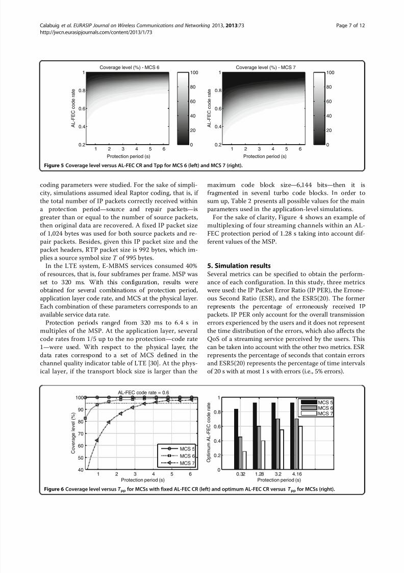
Figure 5 Coverage level versus AL-FEC CR and Tpp for MCS 6 (left) and MCS 7 (right).
AL-FEC code rate = 0.6
1 2 3 4 5 640
50
60
70
80
90
100
Protection period (s)
C o v e r a g e l e v e l ( % )
MCS 5
MCS 6
MCS 7
0.32 1.28 3.2 4.160
0.2
0.4
0.6
0.8
1
Protection period (s)
O p t i m u m
A L - F E C c o d e r a t e MCS 5
MCS 6MCS 7
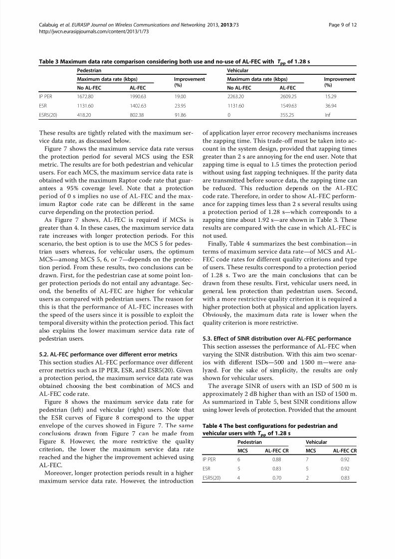
Figure 6 Coverage level versus T pp for MCSs with fixed AL-FEC CR (left) and optimum AL-FEC CR versus T pp for MCSs (right).
Calabuig et al. EURASIP Journal on Wireless Communications and Networking 2013, 2013:73 Page 7 of 12
http://jwcn.eurasipjournals.com/content/2013/1/73

8/10/2019 AL-FEC for Streaming Services in LTE E-MBMS
http://slidepdf.com/reader/full/al-fec-for-streaming-services-in-lte-e-mbms 8/12
On the other hand, three are the performance indica-
tors assessed in this article: outage probability, coveragelevel and maximum, service data rate. For each consid-
ered metric, –i.e., IP PER, ESR, and ESR5(20), a user is
in outage when experiencing a value greater than 1%.
The coverage level for a given configuration represents
the percentage of users that are not in outage for this
configuration. Finally, the maximum service data rate is
defined as the higher data rate that presents a coverage
value greater than 95%. Both coverage level and max-
imum service data rate are computed for each metric.
5.1. Performance assessment for different AL-FEC
configurationsIn this section, the trade-off between PHY-FEC and AL-
FEC is investigated along with the influence of the pro-
tection period. Figure 5 shows an example of coverage
performance of E-MBMS for different AL-FEC configu-
rations, i.e., application code rate and protection period
combinations. The left part corresponds to MCS 6 and
the right part to MCS 7. In this case, ESR criterion was
chosen and only vehicular users were deployed with an
ISD scenario of 500 m.In general, the coverage level depends on the MCS,
obtaining better coverage for more robust MCS. Of
course, higher robustness comes at the expense of a
lower service date rate. According to the figure, without
AL-FEC—AL-FEC code rate 1—both MCS 6 and MCS 7
are unable to meet coverage needs. However, the
utilization of AL-FEC improves coverage. In particular,
the coverage level increases with lower code rates and
higher protection periods.
Left part of Figure 6 depicts the coverage level as a
function of the protection period for several MCS with
fixed AL-FEC code rate. These results reinforce the ideathat coverage level increases with more robust MCSs
and higher protection periods.
On the other hand, the optimum AL-FEC code rate is
different depending on the MCS and protection period
values. This is shown on the right part of Figure 6. As it
can be seen, the optimum AL-FEC code rate is higher
with larger protection periods and more robust MCSs.
Pedestrian
0 1 2 3 4 5 60
0.2
0.4
0.6
0.8
1
1.2
1.4
1.6
1.8
Protection period (s)
M a x i m u m
s e r v i c e d a t a r a t e
( M b p s )
MCS 3 MCS 4 MCS 5 MCS 6 MCS 7 MCS 8
0 1 2 3 4 5 60
0.2
0.4
0.6
0.8
1
1.2
1.4
1.6
1.8
Protection period (s)
M a x i m u m
s e r v i c e d a t a r a t e
( M b p s )
Figure 7 Maximum service data rate versus T pp for MCSs with ESR metric for pedestrian (left) and vehicular (right) users.
Pedestrian
0 1 2 3 4 5 60
0.5
1
1.5
2
2.5
3
Protection period (s)
M a x i m u m
s e r v i c e d a t a r a t e ( M b p
s )
IP PER ESR ESR5(20)
Vehicular
0 1 2 3 4 5 60
0.5
1
1.5
2
2.5
3
Protection period (s)
M a x i m u m
s e r v i c e d a t a r a t e ( M b p
s )
Figure 8 Maximum service data rate versus T pp for several metrics for pedestrian (left) and vehicular (right) users.
Calabuig et al. EURASIP Journal on Wireless Communications and Networking 2013, 2013:73 Page 8 of 12
http://jwcn.eurasipjournals.com/content/2013/1/73
8/10/2019 AL-FEC for Streaming Services in LTE E-MBMS
http://slidepdf.com/reader/full/al-fec-for-streaming-services-in-lte-e-mbms 9/12
These results are tightly related with the maximum ser-
vice data rate, as discussed below.
Figure 7 shows the maximum service data rate versus
the protection period for several MCS using the ESR
metric. The results are for both pedestrian and vehicular
users. For each MCS, the maximum service data rate is
obtained with the maximum Raptor code rate that guar-
antees a 95% coverage level. Note that a protection
period of 0 s implies no use of AL-FEC and the max-imum Raptor code rate can be different in the same
curve depending on the protection period.
As Figure 7 shows, AL-FEC is required if MCSs is
greater than 4. In these cases, the maximum service data
rate increases with longer protection periods. For this
scenario, the best option is to use the MCS 5 for pedes-
trian users whereas, for vehicular users, the optimum
MCS—among MCS 5, 6, or 7—depends on the protec-
tion period. From these results, two conclusions can be
drawn. First, for the pedestrian case at some point lon-
ger protection periods do not entail any advantage. Sec-
ond, the benefits of AL-FEC are higher for vehicularusers as compared with pedestrian users. The reason for
this is that the performance of AL-FEC increases with
the speed of the users since it is possible to exploit the
temporal diversity within the protection period. This fact
also explains the lower maximum service data rate of
pedestrian users.
5.2. AL-FEC performance over different error metrics
This section studies AL-FEC performance over different
error metrics such as IP PER, ESR, and ESR5(20). Given
a protection period, the maximum service data rate was
obtained choosing the best combination of MCS and
AL-FEC code rate.Figure 8 shows the maximum service data rate for
pedestrian (left) and vehicular (right) users. Note that
the ESR curves of Figure 8 correspond to the upper
envelope of the curves showed in Figure 7. The same
conclusions drawn from Figure 7 can be made from
Figure 8. However, the more restrictive the quality
criterion, the lower the maximum service data rate
reached and the higher the improvement achieved using
AL-FEC.
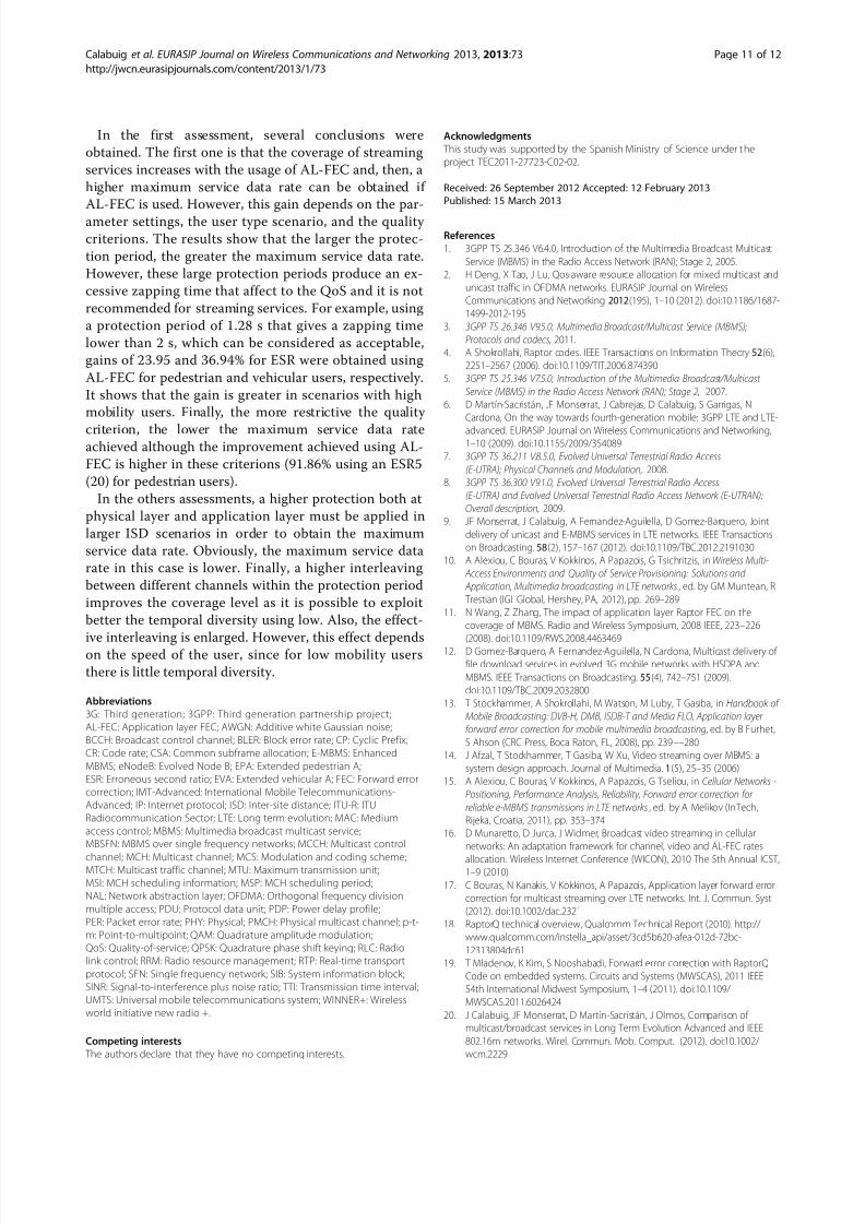
Moreover, longer protection periods result in a higher
maximum service data rate. However, the introduction
of application layer error recovery mechanisms increases
the zapping time. This trade-off must be taken into ac-
count in the system design, provided that zapping times
greater than 2 s are annoying for the end user. Note that
zapping time is equal to 1.5 times the protection period
without using fast zapping techniques. If the parity data
are transmitted before source data, the zapping time can
be reduced. This reduction depends on the AL-FEC
code rate. Therefore, in order to show AL-FEC perform-ance for zapping times less than 2 s several results using
a protection period of 1.28 s—which corresponds to a
zapping time about 1.92 s—are shown in Table 3. These
results are compared with the case in which AL-FEC is
not used.
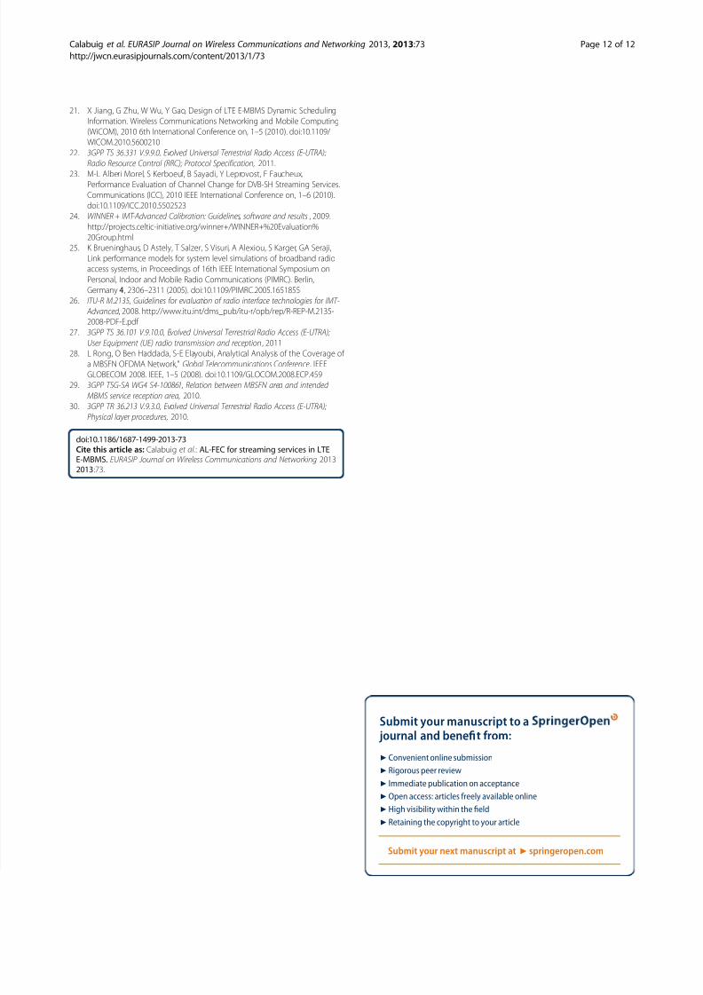
Finally, Table 4 summarizes the best combination—in
terms of maximum service data rate—of MCS and AL-
FEC code rates for different quality criterions and type
of users. These results correspond to a protection period
of 1.28 s. Two are the main conclusions that can be
drawn from these results. First, vehicular users need, in
general, less protection than pedestrian users. Second,with a more restrictive quality criterion it is required a
higher protection both at physical and application layers.
Obviously, the maximum data rate is lower when the
quality criterion is more restrictive.
5.3. Effect of SINR distribution over AL-FEC performance
This section assesses the performance of AL-FEC when
varying the SINR distribution. With this aim two scenar-
ios with different ISDs—500 and 1500 m—were ana-
lyzed. For the sake of simplicity, the results are only
shown for vehicular users.
The average SINR of users with an ISD of 500 m is
approximately 2 dB higher than with an ISD of 1500 m.As summarized in Table 5, best SINR conditions allow
using lower levels of protection. Provided that the amount
Table 3 Maximum data rate comparison considering both use and no-use of AL-FEC with T pp of 1.28 s
Pedestrian Vehicular
Maximum data rate (kbps) Improvement(%)
Maximum data rate (kbps) Improvement(%)
No AL-FEC AL-FEC No AL-FEC AL-FEC
IP PER 1672.80 1990.63 19.00 2263.20 2609.25 15.29ESR 1131.60 1402.63 23.95 1131.60 1549.63 36.94
ESR5(20) 418.20 802.38 91.86 0 355.25 Inf
Table 4 The best configurations for pedestrian and
vehicular users with T pp of 1.28 s
Pedestrian Vehicular
MCS AL-FEC CR MCS AL-FEC CR
IP PER 6 0.88 7 0.92
ESR 5 0.83 5 0.92
ESR5(20) 4 0.70 2 0.83
Calabuig et al. EURASIP Journal on Wireless Communications and Networking 2013, 2013:73 Page 9 of 12
http://jwcn.eurasipjournals.com/content/2013/1/73

8/10/2019 AL-FEC for Streaming Services in LTE E-MBMS
http://slidepdf.com/reader/full/al-fec-for-streaming-services-in-lte-e-mbms 10/12
of resources reserved for E-MBMS is the same, this ro-
bustness implies that the maximum service data rate is
higher for smaller ISD scenarios.
5.4. Performance assessment for different configurations
of the scheduling of E-MBMS
So far, the results have been obtained assuming that one
service channel occupies all the resources allocated to E-
MBMS and MSP is 320 ms. This section studies the ef-
fect of E-MBMS scheduling on AL-FEC performance.The assessment is performed using the example showed
in Figure 4, where four streaming channels are multiplexed
within the protection period using different values of the
MSP. Figure 4 showed that the higher the MSP, the lower
the resources dedicated to E-MBMS control. However, a
high MSP reduces time diversity. This section analyzes this
trade-off.
As explained in Section 5.2, the performance of AL-
FEC improves with the user velocity, since it is possible
to exploit the temporal diversity within the protection
period. This is why this section focuses on a vehicular
scenario. Besides, two different protection periods—
1.28and 5.12 s—and several MSPs were analyzed. ESR metric
was used.
Figure 9 shows the coverage level as a function of the
AL-FEC code rate and the MSP. MCS 7 was used for a
protection period of 1.28 s (left) and MCS 8 for a pro-
tection period of 5.12 s (right). On the one hand, using
low MSPs implies more resource dedicated to E-MBMS
signaling. For example, with a protection period of 1.28
s 16 MSI are transmitted using an MSP of 80 ms,
whereas only 4 MSI are required with an MSP of 320
ms. However, the results show that, for a given AL-FEC
code rate, the lower the MSP, the higher the coverage
level. Indeed, using a low MSP allows for a better ex-
ploitation of temporal diversity since each E-MBMS
channel transmission is divided into several intervals
within the protection period. Despite the additional sig-
naling overhead, this entails a larger effective interleav-
ing and a better performance. In addition, the effect of
the MSP is more significant for longer protection pe-riods since there is more room for time interleaving. It is
worth noting that this effect depends on the speed of the
user, since for low mobility users there is little temporal
diversity. In fact, similar simulations were performed for
pedestrian users and this effect was not noticeable.
6. ConclusionsThis article has presented some guidelines for the effi-
cient transmission of E-MBMS services proposing the
utilization of AL-FEC protection based on Raptor codes
for the transmission of streaming services over LTE net-
works. With this aim, this article has taken into accountthe RRM problem and the trade-off between PHY-FEC
and AL-FEC. Several AL-FEC configurations with differ-
ent protection periods and code rates have been com-
pared with the transmission of streaming services
without AL-FEC protection. This article has also studied
the effect of several AL-FEC parameters on system per-
formance in several scenarios with different average
SINRs and the effect on time multiplexing of different
services within the AL-FEC time interleaving.
Table 5 The best configurations for different ISDs for vehicular users with T pp of 1.28 s
ISD 500 m ISD 1500 m
MCS AL-FEC CR Maximum data rate (kbps) MCS AL-FEC CR Maximum data rate (kbps)
IP PER 7 0.92 2609.25 5 0.70 1182.13
ESR 5 0.92 1549.63 3 0.84 594.13ESR5(20) 2 0.83 355.25 2 0.26 110.25
Coverage level (%) - MCS 7 - Tpp = 1.28 s
0.2
0.4
0.6
0.8
MCH scheduling period (ms)
A L - F E C c o d e r a t e
0
20
40
60
80
100Coverage level (%) - MCS 8 - Tpp = 5.12 s
200 400 600 800 1000 1200 1000 2000 3000 4000 50000.2
0.4
0.6
0.8
MCH scheduling period (ms)
A L - F E C c o d e r a t e
0
20
40
60
80
100
Figure 9 Coverage level versus AL-FEC CR and MSP for MCS 7 with T pp of 1.28 s (left) and MCS 8 with T pp of 5.12 s (right).
Calabuig et al. EURASIP Journal on Wireless Communications and Networking 2013, 2013:73 Page 10 of 12
http://jwcn.eurasipjournals.com/content/2013/1/73
8/10/2019 AL-FEC for Streaming Services in LTE E-MBMS
http://slidepdf.com/reader/full/al-fec-for-streaming-services-in-lte-e-mbms 11/12
In the first assessment, several conclusions were
obtained. The first one is that the coverage of streaming
services increases with the usage of AL-FEC and, then, a
higher maximum service data rate can be obtained if
AL-FEC is used. However, this gain depends on the par-
ameter settings, the user type scenario, and the quality
criterions. The results show that the larger the protec-
tion period, the greater the maximum service data rate.
However, these large protection periods produce an ex-
cessive zapping time that affect to the QoS and it is not
recommended for streaming services. For example, using
a protection period of 1.28 s that gives a zapping time
lower than 2 s, which can be considered as acceptable,
gains of 23.95 and 36.94% for ESR were obtained using
AL-FEC for pedestrian and vehicular users, respectively.
It shows that the gain is greater in scenarios with high
mobility users. Finally, the more restrictive the quality
criterion, the lower the maximum service data rateachieved although the improvement achieved using AL-
FEC is higher in these criterions (91.86% using an ESR5
(20) for pedestrian users).
In the others assessments, a higher protection both at
physical layer and application layer must be applied in
larger ISD scenarios in order to obtain the maximum
service data rate. Obviously, the maximum service data
rate in this case is lower. Finally, a higher interleaving
between different channels within the protection period
improves the coverage level as it is possible to exploit
better the temporal diversity using low. Also, the effect-
ive interleaving is enlarged. However, this effect dependson the speed of the user, since for low mobility users
there is little temporal diversity.
Abbreviations
3G: Third generation; 3GPP: Third generation partnership project;
AL-FEC: Application layer FEC; AWGN: Additive white Gaussian noise;
BCCH: Broadcast control channel; BLER: Block error rate; CP: Cyclic Prefix;
CR: Code rate; CSA: Common subframe allocation; E-MBMS: Enhanced
MBMS; eNodeB: Evolved Node B; EPA: Extended pedestrian A;
ESR: Erroneous second ratio; EVA: Extended vehicular A; FEC: Forward error
correction; IMT-Advanced: International Mobile Telecommunications-
Advanced; IP: Internet protocol; ISD: Inter-site distance; ITU-R: ITU
Radiocommunication Sector; LTE: Long term evolution; MAC: Medium
access control; MBMS: Multimedia broadcast multicast service;MBSFN: MBMS over single frequency networks; MCCH: Multicast control
channel; MCH: Multicast channel; MCS: Modulation and coding scheme;MTCH: Multicast traffic channel; MTU: Maximum transmission unit;
MSI: MCH scheduling information; MSP: MCH scheduling period;
NAL: Network abstraction layer; OFDMA: Orthogonal frequency division
multiple access; PDU: Protocol data unit; PDP: Power delay profile;
PER: Packet error rate; PHY: Physical; PMCH: Physical multicast channel; p-t-
m: Point-to-multipoint; QAM: Quadrature amplitude modulation;
QoS: Quality-of-service; QPSK: Quadrature phase shift keying; RLC: Radio
link control; RRM: Radio resource management; RTP: Real-time transport
protocol; SFN: Single frequency network; SIB: System information block;
SINR: Signal-to-interference plus noise ratio; TTI: Transmission time interval;
UMTS: Universal mobile telecommunications system; WINNER+: Wireless
world initiative new radio +.
Competing interests
The authors declare that they have no competing interests.
Acknowledgments
This study was supported by the Spanish Ministry of Science under t he
project TEC2011-27723-C02-02.
Received: 26 September 2012 Accepted: 12 February 2013
Published: 15 March 2013
References
1. 3GPP TS 25.346 V6.4.0, Introduction of the Multimedia Broadcast Multicast
Service (MBMS) in the Radio Access Network (RAN); Stage 2, 2005.
2. H Deng, X Tao, J Lu, Qos-aware resource allocation for mixed multicast and
unicast traffic in OFDMA networks. EURASIP Journal on Wireless
Communications and Networking 2012(195), 1–10 (2012). doi:10.1186/1687-
1499-2012-195
3. 3GPP TS 26.346 V9.5.0, Multimedia Broadcast/Multicast Service (MBMS);
Protocols and codecs, 2011.
4. A Shokrollahi, Raptor codes. IEEE Transactions on Information Theory 52(6),
2251–2567 (2006). doi:10.1109/TIT.2006.874390
5. 3GPP TS 25.346 V7.5.0, Introduction of the Multimedia Broadcast/Multicast
Service (MBMS) in the Radio Access Network (RAN); Stage 2, 2007.
6. D Martín-Sacristán, JF Monserrat, J Cabrejas, D Calabuig, S Garrigas, N
Cardona, On the way towards fourth-generation mobile: 3GPP LTE and LTE-
advanced. EURASIP Journal on Wireless Communications and Networking,1–10 (2009). doi:10.1155/2009/354089
7. 3GPP TS 36.211 V.8.5.0, Evolved Universal Terrestrial Radio Access
(E-UTRA); Physical Channels and Modulation, 2008.
8. 3GPP TS 36.300 V9.1.0, Evolved Universal Terrestrial Radio Access
(E-UTRA) and Evolved Universal Terrestrial Radio Access Network (E-UTRAN);
Overall description, 2009.
9. JF Monserrat, J Calabuig, A Fernandez-Aguilella, D Gomez-Barquero, Joint
delivery of unicast and E-MBMS services in LTE networks. IEEE Transactions
on Broadcasting. 58(2), 157–167 (2012). doi:10.1109/TBC.2012.2191030
10. A Alexiou, C Bouras, V Kokkinos, A Papazois, G Tsichritzis, in Wireless Multi-
Access Environments and Quality of Service Provisioning: Solutions and
Application, Multimedia broadcasting in LTE networks , ed. by GM Muntean, R
Trestian (IGI Global, Hershey, PA, 2012), pp. 269–289
11. N Wang, Z Zhang, The impact of application layer Raptor FEC on the
coverage of MBMS. Radio and Wireless Symposium, 2008 IEEE, 223–226
(2008). doi:10.1109/RWS.2008.446346912. D Gomez-Barquero, A Fernandez-Aguilella, N Cardona, Multicast delivery of
file download services in evolved 3G mobile networks with HSDPA and
MBMS. IEEE Transactions on Broadcasting. 55(4), 742–751 (2009).
doi:10.1109/TBC.2009.2032800
13. T Stockhammer, A Shokrollahi, M Watson, M Luby, T Gasiba, in Handbook of
Mobile Broadcasting: DVB-H, DMB, ISDB-T and Media FLO, Application layer
forward error correction for mobile multimedia broadcasting, ed. by B Furhet,
S Ahson (CRC Press, Boca Raton, FL, 2008), pp. 239––280
14. J Afzal, T Stockhammer, T Gasiba, W Xu, Video streaming over MBMS: a
system design approach. Journal of Multimedia. 1(5), 25–35 (2006)
15. A Alexiou, C Bouras, V Kokkinos, A Papazois, G Tseliou, in Cellular Networks -
Positioning, Performance Analysis, Reliability, Forward error correction for
reliable e-MBMS transmissions in LTE networks, ed. by A Melikov (InTech,
Rijeka, Croatia, 2011), pp. 353–374
16. D Munaretto, D Jurca, J Widmer, Broadcast video streaming in cellular
networks: An adaptation framework for channel, video and AL-FEC rates
allocation. Wireless Internet Conference (WICON), 2010 The 5th Annual ICST,1–9 (2010)
17. C Bouras, N Kanakis, V Kokkinos, A Papazois, Application layer forward error
correction for multicast streaming over LTE networks. Int. J. Commun. Syst
(2012). doi:10.1002/dac.2321
18. RaptorQ technical overview, Qualcomm Technical Report (2010). http://
www.qualcomm.com/instella_api/asset/3cd5b620-afea-012d-72bc-
12313804dc61
19. T Mladenov, K Kim, S Nooshabadi, Forward error correction with RaptorQ
Code on embedded systems. Circuits and Systems (MWSCAS), 2011 IEEE
54th International Midwest Symposium, 1–4 (2011). doi:10.1109/
MWSCAS.2011.6026424
20. J Calabuig, JF Monserrat, D Martín-Sacristán, J Olmos, Comparison of multicast/broadcast services in Long Term Evolution Advanced and IEEE
802.16m networks. Wirel. Commun. Mob. Comput. (2012). doi:10.1002/
wcm.2229
Calabuig et al. EURASIP Journal on Wireless Communications and Networking 2013, 2013:73 Page 11 of 12
http://jwcn.eurasipjournals.com/content/2013/1/73
8/10/2019 AL-FEC for Streaming Services in LTE E-MBMS
http://slidepdf.com/reader/full/al-fec-for-streaming-services-in-lte-e-mbms 12/12
21. X Jiang, G Zhu, W Wu, Y Gao, Design of LTE E-MBMS Dynamic Scheduling
Information. Wireless Communications Networking and Mobile Computing
(WiCOM), 2010 6th International Conference on, 1–5 (2010). doi:10.1109/
WICOM.2010.5600210
22. 3GPP TS 36.331 V.9.9.0, Evolved Universal Terrestrial Radio Access (E-UTRA);
Radio Resource Control (RRC); Protocol Specification, 2011.
23. M-L Alberi Morel, S Kerboeuf, B Sayadi, Y Leprovost, F Faucheux,Performance Evaluation of Channel Change for DVB-SH Streaming Services.
Communications (ICC), 2010 IEEE International Conference on, 1–6 (2010).
doi:10.1109/ICC.2010.5502523
24. WINNER + IMT-Advanced Calibration: Guidelines, software and results , 2009.
http://projects.celtic-initiative.org/winner+/WINNER+%20Evaluation%
20Group.html
25. K Brueninghaus, D Astely, T Salzer, S Visuri, A Alexiou, S Karger, GA Seraji,
Link performance models for system level simulations of broadband radio
access systems, in Proceedings of 16th IEEE International Symposium on
Personal, Indoor and Mobile Radio Communications (PIMRC). Berlin,
Germany 4, 2306–2311 (2005). doi:10.1109/PIMRC.2005.1651855
26. ITU-R M.2135, Guidelines for evaluation of radio interface technologies for IMT-
Advanced , 2008. http://www.itu.int/dms_pub/itu-r/opb/rep/R-REP-M.2135-
2008-PDF-E.pdf
27. 3GPP TS 36.101 V.9.10.0, Evolved Universal Terrestrial Radio Access (E-UTRA);
User Equipment (UE) radio transmission and reception, 2011
28. L Rong, O Ben Haddada, S-E Elayoubi, Analytical Analysis of the Coverage of
a MBSFN OFDMA Network," Global Telecommunications Conference. IEEE
GLOBECOM 2008. IEEE, 1–5 (2008). doi:10.1109/GLOCOM.2008.ECP.459
29. 3GPP TSG-SA WG4 S4-100861, Relation between MBSFN area and intended
MBMS service reception area, 2010.
30. 3GPP TR 36.213 V.9.3.0, Evolved Universal Terrestrial Radio Access (E-UTRA);
Physical layer procedures, 2010.
doi:10.1186/1687-1499-2013-73Cite this article as: Calabuig et al.: AL-FEC for streaming services in LTEE-MBMS. EURASIP Journal on Wireless Communications and Networking 20132013:73.
Submit your manuscript to a journal and benefit from:
7 Convenient online submission
7
Rigorous peer review
7 Immediate publication on acceptance
7 Open access: articles freely available online
7
High visibility within the field
7 Retaining the copyright to your article
Submit your next manuscript at7 springeropen.com
Calabuig et al. EURASIP Journal on Wireless Communications and Networking 2013, 2013:73 Page 12 of 12
http://jwcn.eurasipjournals.com/content/2013/1/73