feasibility analysis of mbms deployment with the
TRANSCRIPT
Feasibility analysis of MBMS deployment
with the introduction of LTE
SIMA HOSSEINI HOOSHYAR
Master’s Degree Project
Stockholm, Sweden November 2013
XR-EE-LCN 2013:017
KTH Electrical Engineering
Master of Science Thesis
Feasibility analysis of MBMS deployment with the introduction of LTE
Sima Hosseini Hooshyar
Supervisor and Examiner
György Dán, Associate professor, Laboratory for Communication Networks (LCN), KTH, Stockholm.
Jiang Wu, Sr. Specialist IP RAN, Ericsson, Stockholm
Lab for Communication Networks (LCN)
School of Electrical Engineering
Kungliga Tekniska Högskolan (KTH)
Stockholm, Sweden

2
3
Abstract
Multimedia Broadcast Multicast service (MBMS) proposed by 3GPP for efficient use of network resources in broadcast and multicast services, provides the operator a delivery mechanism to simultaneously send to multiple recipients at high speed. Although MBMS was introduced in 3GPP Release 6 at the time of 3G networks, the MBMS feature did not find much attention from the 3G network operators. This thesis studies the technical and market feasibility for a successful MBMS deployment today at the time of commercial LTE deployment. UE and RAN advancements that make MBMS technologically feasible are studied together with the market feasibility factors such as user demand on media streaming and the impending data explosion. The thesis concludes that today at the time of LTE, it is more feasible from both technology and market perspectives to deploy MBMS in comparison to the time of 3G. As a future work, the thesis provides some suggestions that the operators should take care of before deploying MBMS.

4
5
Acknowledgment
This thesis has been done at the School of Electrical Engineering at KTH and at Ericsson.
I would like to express my gratitude to my supervisor György Dán for the useful comments, remarks and engagement through the learning process of this master thesis. Furthermore I would like to thank Jiang Wu for introducing me to the topic as well for the support on the way. Also, I like to thank the participants in my survey, who have willingly shared their precious time during the process of interviewing. I would like to thank my loved ones, my parents, who have supported me throughout entire process, both by keeping me harmonious and helping me putting pieces together. I will be grateful forever for your love and I dedicate this thesis to you.
Sima Hosseini Hooshyar Stockholm Nov 2013

6

7
To my lovely parents
8
Contents
CHAPTER 1.................................................................................................................................................................. 15
INTRODUCTION ........................................................................................................................................................... 15
1.1. Thesis Outline ........................................................................................................................................... 17
1.2. Methodology ............................................................................................................................................. 17
CHAPTER 2.................................................................................................................................................................. 18
BACKGROUND ............................................................................................................................................................. 18
2.1 MBMS architecture ................................................................................................................................... 18
2.1.1 BM-SC functions ........................................................................................................................................................... 19 2.1.2 MBMS service delivery phases..................................................................................................................................... 21
2.1.2.1 Delivery phases for broadcast bearer mode ....................................................................................................... 21 2.1.2.2 Delivery phases for multicast bearer mode ........................................................................................................ 23
2.2 Radio bearer realization for MBMS ......................................................................................................... 25
2.2.1 New logical and physical channels ............................................................................................................................... 25 2.2.2 Channel requirements .................................................................................................................................................... 26 2.2.3 PtP and PtM bearer realization...................................................................................................................................... 28
2.2.3.1 Counting mechanism ........................................................................................................................................... 28
2.3 MBMS bearer service ............................................................................................................................... 29
2.3.1 Broadcast and Multicast mode ...................................................................................................................................... 29
2.4 MBMS user services.................................................................................................................................. 30
2.4.1 MBMS Delivery methods ............................................................................................................................................. 30 2.4.2 Packet error recovery scheme ....................................................................................................................................... 31
CHAPTER 3.................................................................................................................................................................. 33
TECHNOLOGICAL FEASIBILITY .................................................................................................................................... 33
3.1 RAN technology advancements since 3G .................................................................................................. 33
3.1.1 eMBMS architecture ...................................................................................................................................................... 33 3.1.2 MBSFN........................................................................................................................................................................... 34 3.1.3 HSPA+ ............................................................................................................................................................................ 36
3.2 UE technology advancements for eMBMS............................................................................................... 38
3.2.1 Macro diversity and MIMO .......................................................................................................................................... 38 3.2.2 Throughput improvements with diversity .................................................................................................................... 40 3.2.3 Power saving .................................................................................................................................................................. 40
CHAPTER 4.................................................................................................................................................................. 42
MARKET FEASIBILITY ................................................................................................................................................. 42
4.1 UE evolution since 3G .............................................................................................................................. 42
4.2 User demand ............................................................................................................................................. 44
4.2.1 User expectations for mobile media streaming ............................................................................................................ 44 4.2.1.1 Quality of Internet connection ................................................................................................................................. 44 4.2.1.2 UE battery consumption ........................................................................................................................................... 44 4.2.1.3 UE screen resolution................................................................................................................................................. 45 4.2.1.4 Interests ..................................................................................................................................................................... 45 4.2.1.5 Economic status ........................................................................................................................................................ 45 4.2.1.6 General technical awareness .................................................................................................................................... 45 4.2.1.7 Spare Time ................................................................................................................................................................ 46

9
4.2.2 Survey results ................................................................................................................................................................. 46
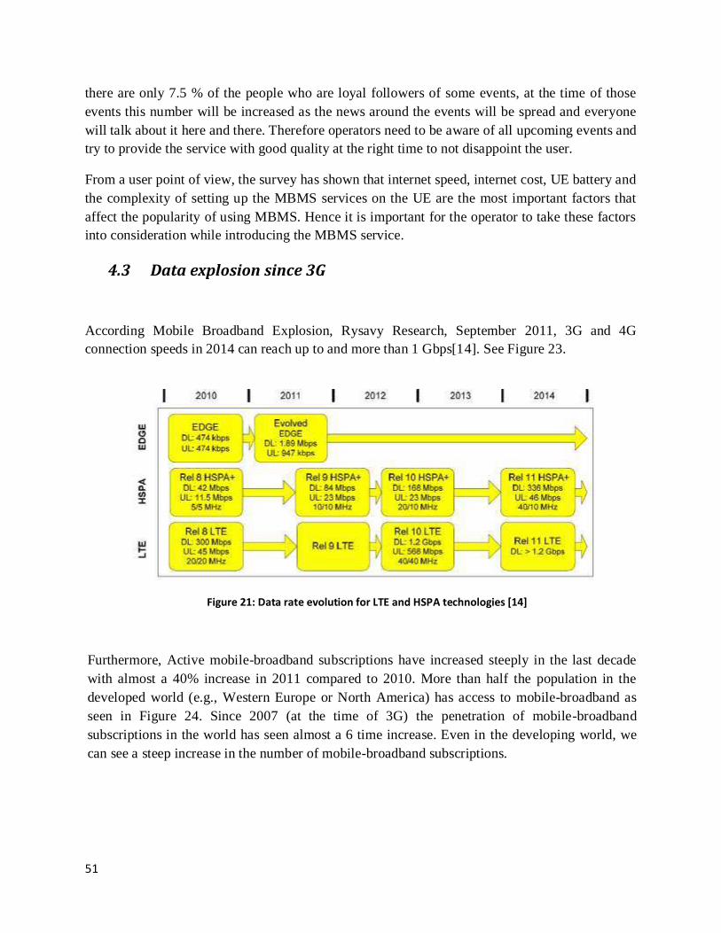
4.3 Data explosion since 3G ........................................................................................................................... 51
CHAPTER 5.................................................................................................................................................................. 54
CONCLUSION ................................................................................................................................................................... 54
FUTURE WORK ................................................................................................................................................................. 55
10
List of figures Figure 1: MBMS architecture in 3G networks ........................................................................................ 18
Figure 2: BM-SC Functions .................................................................................................................... 20
Figure 3: MBMS service protection key hierarchy .................................................................................. 20
Figure 4: Various delivery phases of broadcast mode............................................................................. 21
Figure 5: Example for different delivery phases for broadcast mode ..................................................... 23
Figure 6: Various delivery phases of multicast mode .............................................................................. 23
Figure 7: Example for different delivery phases for multicast mode ....................................................... 24
Figure 8: UMTS interface ....................................................................................................................... 25
Figure 9: MBMS channel mapping ......................................................................................................... 26
Figure 10:RRC states .............................................................................................................................. 27
Figure 11: Counting procedure .............................................................................................................. 29
Figure 12: eMBMS network architecture ............................................................................................... 34
Figure 13:MBSFN area ........................................................................................................................... 35
Figure 14: Two proposed architectures of MCE ..................................................................................... 36
Figure 15 : Spectral efficiency evolution for LTE and UMTS networks .................................................... 37
Figure 16: Latency by different mobile technology ................................................................................ 38
Figure 17: MBMS carrier throughput .................................................................................................... 40
Figure 18: UE talk time evolution ........................................................................................................... 43
Figure 19 : People who are interested in watching media on the mobile based on Gender. ................... 47
Figure 20 : People who are interested in watching media on the mobile based on Age. ......................... 48
Figure 21: Data rate evolution for LTE and HSPA technologies .............................................................. 51
Figure 22: Active mobile broadband subscriptions ................................................................................ 52
Figure 23: Mobile traffic growth by type of traffic ................................................................................. 52
Figure 24: Global Mobile Device Growth by type .................................................................................. 53
11
List of tables
Table 1:RRC state description ................................................................................................................... 26
Table 2 : Power Consumption in RRC states .............................................................................................. 27
Table 3 : Age groups ................................................................................................................................. 47
12
List of acronyms
3GPP Multimedia Broadcast Multicast Service
BM-SC 3rd Generation Partnership Project
CBS Cell Broadcast Service
DP IP Multicast Service
eMBMS Single Frequency Network
EPS Integrated Mobile Broadcast
FACH User Equipment
FDD Broadcast/Multicast Service center
GGSN MBMS Traffic Key
HSPA MBMS Service Key
HSPDA Evolved packet system
HSPUA Gateway GPRS Support Node
IMB User Plane
IP-MS Data Plane
ISI Point to point
LTE Point to Multipoint
MBMS MBMS Control Channel
MBSFN MBMS Traffic Channel
MCCH MBMS Scheduling Channel
MCE MBMS notification Indicator
MICH Forward Access Channel
MIMO Secondary Common Control Physical Channel

13
MSCH Wireless Application Protocol
MSK Long Term Evolution
MTCH Orthogonal Frequency Division Multiplexing
MTK MBMS Single Frequency Network
OFDM enhanced MBMS
PiP Inter Symbol Interference
PtM Multicell/ Multicast Coordination Entity
PtP Radio Resource Control
RRC UTRAN Registration Areas
RTT Transmission Time Interval
S-CCPCH Picture-in-Picture
SFN Transmit Power Control
TDD High Speed Packet Access
TPC High Speed Packet Downlink access
TTI High Speed Packet UpLink
TTI Round Trip Time
UE Transmission Time Interval
UP Multiple Input Multiple Output
URA Time Division Duplex
WAP Frequency Division Duplex

14
15
Chapter 1
Introduction The demand for video streaming on mobile phones has grown exponentially in recent years. To overcome this growing demand, operators must deal with their resource scarcity and find a proper solution to make efficient use of their network resources. Using different type of delivery mechanisms such as unicast, broadcast and multicast in different scenarios can be one solution. Video streaming using unicast delivery requires huge bandwidth in the radio network. If there is a group of users streaming the same content at the same time, unicast is not resource efficient, since there will be multiple radio channels transmitting the same information. Bandwidth allocation to each operator is usually fixed and operators run out of their allocated spectrum if unicast is their only way of data delivery. If the number of users interested in a particular video stream is not high, unicast may still be a good solution. The 3rd Generation Partnership Project (3GPP) organization has proposed different solutions that can fit to most of the operators/vendors/users’ growing needs by sharing resources between the users. This could be using broadcast/multicast as data delivery mechanisms in the radio access, transport or core networks or in a combination of these networks. Broadcasting/Multicasting in the radio access network is one solution to provide better utilization of the scarce radio resources. Cell Broadcast Service (CBS), defined in [1] and [2] is one such service where short messages can be sent to multiple users at the same time. The bandwidth made available by CBS is quite small though, making it suitable only for short and quick network updates and such. Multicasting in the transport network (which is between the radio access and core networks) is provided by IP Multicast Service (IP-MS) solution [3] [6]. Deploying only IP-MS, where there is no capability to share resources in the radio/core networks is not an efficient end-to-end solution for video streaming from an operator point of view. Here one feels a need to integrate IP-MS with other solutions where the radio/core network resources can also be shared. Multimedia Broadcast Multicast Service (MBMS) [5] is one of the solutions proposed by 3GPP. MBMS is introduced in 3GPP release 6 as a new feature which is applicable to GSM and UMTS networks in order to improve efficient use of resources in radio/transport/core networks. BCMCS, Broadcast Multicast Service, refers to the same feature but derived by 3GPP2. MBMS service is improving continuously in each new release since Release 6.
16
In Release 6, MBMS takes advantage of soft combining, which improves the performance at the cell edges. With soft combining, UE will be able to combine the MBMS signals transmitted from multiple adjacent cells. But since the scrambling codes in adjacent cells are different and the signals are not orthogonal, the signals received from an adjacent cell can cause interference to the MBMS reception. With the introduction of single frequency network (SFN) in Release 7, the same frequency and scrambling codes are used in adjacent synchronized cells. Therefore an UE at the cell edge receives multiple versions of the same signal from different cells. The received signal at the UE is then very similar to a signal received from a single transmitter through a multipath propagation channel. Soft combining together with SFN further increases the performance at the cell edges. In 3GPP release 8, Integrated Mobile Broadcast (IMB) is introduced to utilize the allocated TDD 3G spectrum that was seldom used by the operators at that time. Since IMB does not share the FDD spectrum used for unicast, the unicast capacity is not affected by the use of IMB. IMB uses SFN to provide its functionality similar to the Mobile Broadcast Single Frequency Network (MBSFN) which was introduced in 3GPP Release 9. In 3GPP release 9, Orthogonal Frequency Division Multiplexing (OFDM) is introduced as part of Long Term Evolution (LTE) standards. OFDM performs better than single-carrier schemes in tackling interference from adjacent cells, and inter symbol interference (ISI). Signals received by the UE at the cell edge from adjacent cells are orthogonal with the introduction of OFDM. Thus soft combining and SFN can be practically deployed. MBMS is not a part of the LTE standard in 3GPP release 8 because of the low interest shown by operators to introduce the service to the market in 3G. This thesis tries to answer “Why MBMS did not become popular in time of 3G and if the introduction of LTE together with the advancements in underlying technologies and changes in market demands can make MBMS popular among operators?”
17
1.1. Thesis Outline
The assumption of this thesis is that the following factors will make the market very conducible for deployment of eMBMS for LTE rather than 3G.
Technological feasibility
o RAN technology advancements since 3G
o UE technology advancement for eMBMS
Market feasibility
o UE evolution since 3G
o User demand
o Data explosion since 3G
The thesis has been divided into 5 chapters. Chapter 2 explains the technical details of the MBMS service. Chapter 3 explains the technological feasibility factors while chapter 4 explains market feasibility factors. Chapter 5 is the conclusion and future work that can be done in this field.
1.2. Methodology
The methodologies used in this thesis are interviews, survey and internet research.
Interviews with Product management teams within a major telecommunication equipment vendor helped to get an understanding of why operators were reluctant to buy MBMS at the time of 3G even though the vendor was ready to provide the MBMS itself to the operators. The knowledge from the interviews was used to form the broad structure of this thesis, i.e., to study the technological and market feasibility factors for MBMS deployment in LTE.
Internet research on the advancements in RAN technology and UEs provided the basis for analysis on technological feasibility factors. For the market feasibility factors, a survey was taken from about 200 random mobile phone users in city center of Stockholm and in the inter-city train between Stockholm and linköping.

18
Chapter 2
Background
In Chapter 2 we discuss the MBMS architecture in 3G networks. Furthermore an overall picture of “what is MBMS”, “how does it work from radio bearer perspective”, “what are the different MBMS bearer services” and “what are the different MBMS user services” are given.
2.1 MBMS architecture
MBMS introduces the simultaneous transmission of high bit rate data to several mobile terminals by having minimum impact to the existing network architecture. In fact, only one new network element was added to the existing 3G network architecture, but a number of new tasks were defined for the existing core/ RAN nodes. [1]
Figure 1: MBMS architecture in 3G networks [6]
As it can be seen in Figure 1, Broadcast/Multicast Service center (BM-SC) is the newly added component to the existing 3G architecture in order to support MBMS. The functions that BM-SC is in charge of will be described in section 2.1.1. Additional capabilities that had to be added to the GGSN for it to be able to support MBMS are:
19
o Receiving IP multicast traffic from BM-SC and forward it to those SGSNs that have joined the broadcast or multicast sessions.
o Maintaining the point to multipoint distribution tree. In case of multicast mode, GGSN will establish the distribution tree including all SGSNs who are in charge of serving the subscribers for that specific bearer. In broadcast mode, distribution tree will be established based on a list of SGSNs provided by BS-SC.
2.1.1 BM-SC functions
According to the 3GGP standard [1], the BM-SC functionality has been divided into the following sub-functions:
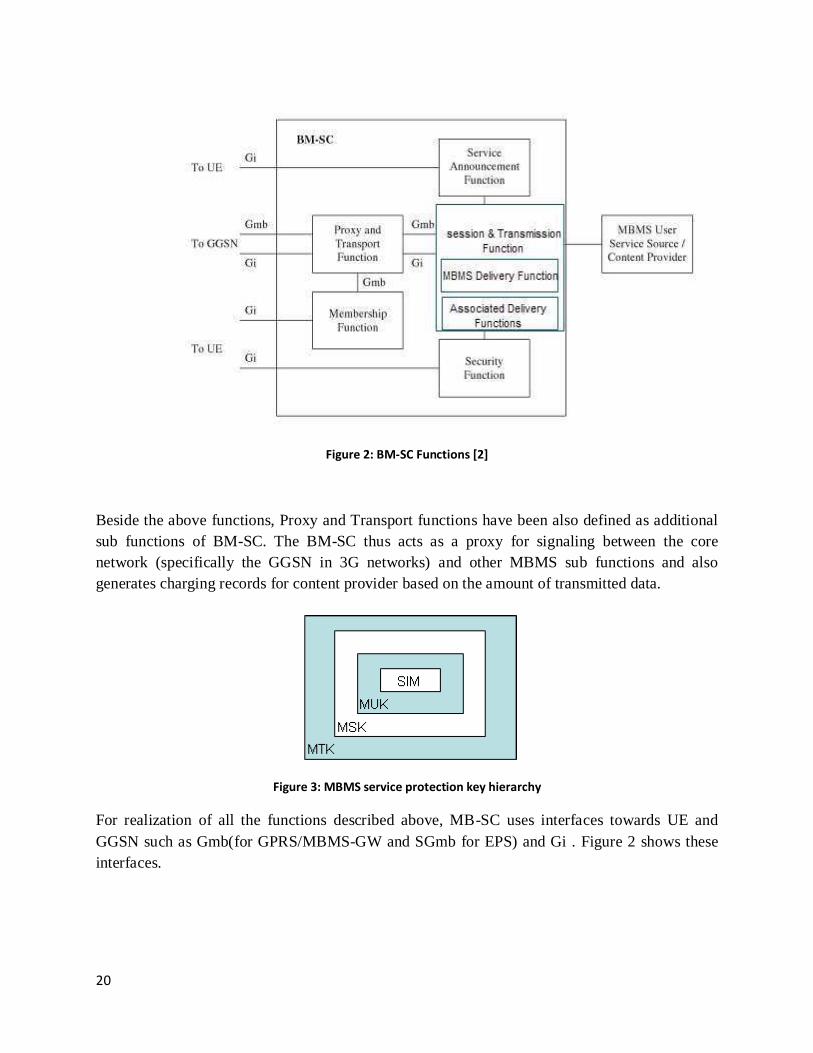
o Session and transmission function: BM-SC handles all the procedures related to real data transmission. As it can be seen in Figure 2, this function is divided into two sub functions: MBMS Delivery Functions including downloading and streaming methods and Associated Delivery Functions such as File Repair and Reception Reporting which will be described later in section 2.4.2.
o Service announcement function: For an end user to join to any MBMS service some information is needed, such as time of transmission, IP multicast addresses and session description. BM-SC provides this information and delivers to the end device in form of several “fragments” using one of the Pulling, using MBMS bearer or Pushing methods. The end device can use Wireless Application Protocol (WAP) like HTTP to download the service announcement whenever it needs it, for example when the end device knows that its present information is expired and needs to be updated. The service announcement can also be pushed to the end user by the BM-SC in form of several SMS. Fragments can be sent via MBMS download delivery method as well.[1][2][3]
o Membership function: BM-SC authenticates and charges the user when it joins to any multicast session and starts to receive MBMS service.
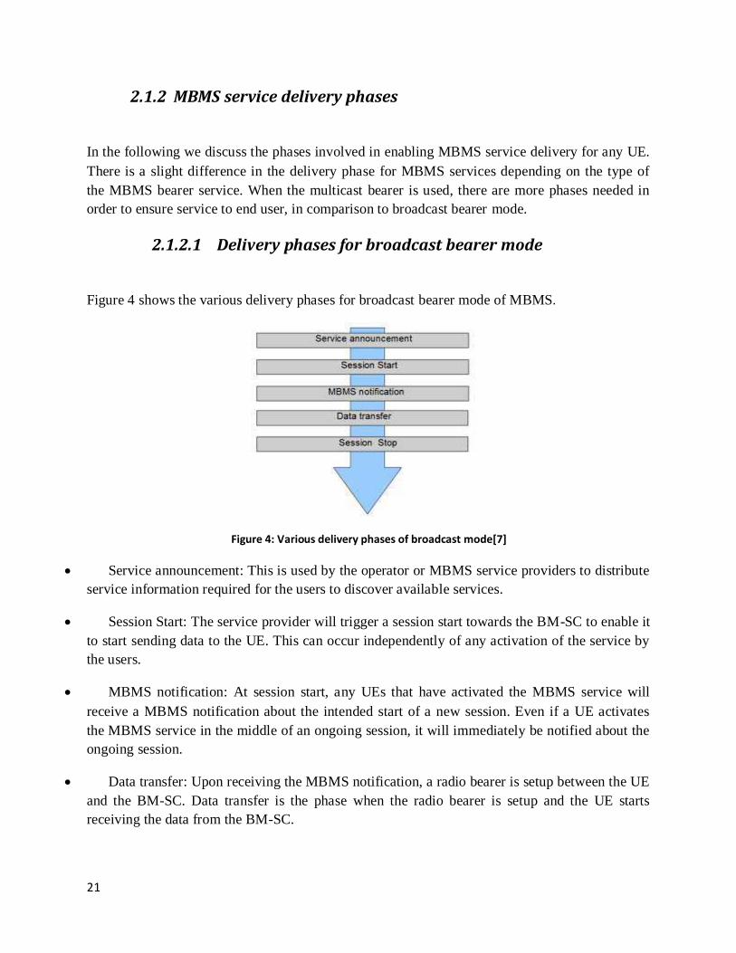
o Security function: in order to protect the data that are supposed to be delivered to end user, BM-SC provides the keys and distributes them to the end users. In this procedure, data traffic will be encrypted using MBMS Traffic Key (MTK). MTK is protected by MBMS Service Key (MSK) which is encrypted by MBMS User Key (MUK) and finally MUK is generated based on the Subscriber Identity Module (SIM). Figure 3 demonstrates the Keys for MBMS data protection.
20
Figure 2: BM-SC Functions [2]
Beside the above functions, Proxy and Transport functions have been also defined as additional sub functions of BM-SC. The BM-SC thus acts as a proxy for signaling between the core network (specifically the GGSN in 3G networks) and other MBMS sub functions and also generates charging records for content provider based on the amount of transmitted data.
Figure 3: MBMS service protection key hierarchy
For realization of all the functions described above, MB-SC uses interfaces towards UE and GGSN such as Gmb(for GPRS/MBMS-GW and SGmb for EPS) and Gi . Figure 2 shows these interfaces.
21
2.1.2 MBMS service delivery phases
In the following we discuss the phases involved in enabling MBMS service delivery for any UE. There is a slight difference in the delivery phase for MBMS services depending on the type of the MBMS bearer service. When the multicast bearer is used, there are more phases needed in order to ensure service to end user, in comparison to broadcast bearer mode.
2.1.2.1 Delivery phases for broadcast bearer mode
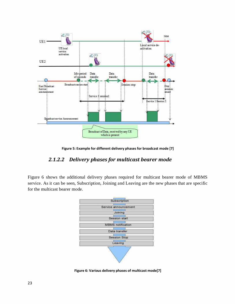
Figure 4 shows the various delivery phases for broadcast bearer mode of MBMS.
Figure 4: Various delivery phases of broadcast mode[7]
Service announcement: This is used by the operator or MBMS service providers to distribute service information required for the users to discover available services.
Session Start: The service provider will trigger a session start towards the BM-SC to enable it to start sending data to the UE. This can occur independently of any activation of the service by the users.
MBMS notification: At session start, any UEs that have activated the MBMS service will receive a MBMS notification about the intended start of a new session. Even if a UE activates the MBMS service in the middle of an ongoing session, it will immediately be notified about the ongoing session.
Data transfer: Upon receiving the MBMS notification, a radio bearer is setup between the UE and the BM-SC. Data transfer is the phase when the radio bearer is setup and the UE starts receiving the data from the BM-SC.

22
Session Stop: This is triggered by the service provider to let the BM-SC know that there won’t be any more data to transmit. At session stop, all the radio bearers corresponding to the session will be released.
Figure 5 demonstrates the different phases explained above using an example where there are two UEs that activate the MBMS service at different points in time. UE1 activates the service before session start, while UE2 activates that service during an ongoing session.
The service provider first announces the start of a broadcast service in the service announcement phase. UE1 and UE2 receive this notification so that they can activate the service whenever they want to. In this example UE1 activates the service before any session has been started by the BM-SC. Once the session start phase is reached, the UE1 will receive a notification to setup the radio bearers and then data will be transferred via the radio bearer. Later, when the session is already in progress, UE2 activates the same service, and after receiving the notification to setup the radio bearer, UE2 will also start receiving the data. Finally, when the session stop is triggered by the service provider, the radio bearers for both UE1 and UE2 will be released.
The service provider in this example has more data to be transmitted, and hence it will trigger another Session Start towards the BM-SC. In this situation, as both UE1 and UE2 are activated for the service before the session start, radio bearers will be immediately set up to start receiving data for the second session. While the session is in progress, UE1 decides to deactivate the MBMS service. At this point the radio bearer setup between the BM-SC and UE1 will be released, whereas the data traffic transmission towards UE2 continues until the Session stop.
23
Figure 5: Example for different delivery phases for broadcast mode [7]
2.1.2.2 Delivery phases for multicast bearer mode
Figure 6 shows the additional delivery phases required for multicast bearer mode of MBMS service. As it can be seen, Subscription, Joining and Leaving are the new phases that are specific for the multicast bearer mode.
Figure 6: Various delivery phases of multicast mode[7]
24
Subscription: This phase is mainly for setting up an agreement between the user and the service provider. The subscription information will be stored in the BM-SC, so that the BM-SC will be able to authenticate and to charge the user appropriately. The subscription can occur independently of the service announcement as explained in the example below.
Joining: This phase is similar to the service activation used in the broadcast mode. Nevertheless, in multicast mode, the UE can join the service only if it has subscribed before. The joining phase can start independent of the service start phase. So the UE can join a session either before the start of a session or during an ongoing session.
Leaving: In this phase UE can stop receiving data corresponding to a particular service. Similar to the joining phase, the leaving process occurs independently of the session stop process.
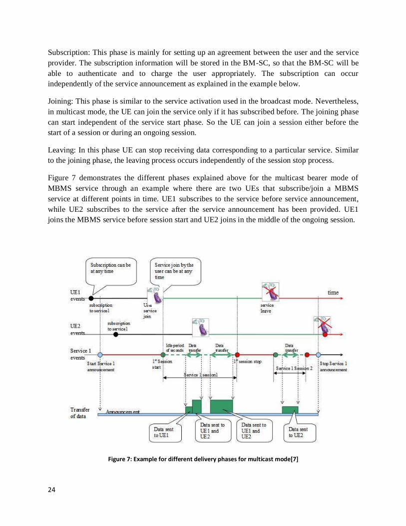
Figure 7 demonstrates the different phases explained above for the multicast bearer mode of MBMS service through an example where there are two UEs that subscribe/join a MBMS service at different points in time. UE1 subscribes to the service before service announcement, while UE2 subscribes to the service after the service announcement has been provided. UE1 joins the MBMS service before session start and UE2 joins in the middle of the ongoing session.
Figure 7: Example for different delivery phases for multicast mode[7]

25
2.2 Radio bearer realization for MBMS
In 3GPP, the channels that are used for transmitting the user plane and control plane data between UE and UTTRAN in Uu interface are known as radio bearers. Figure 8 contains an illustration of the architecture in 3G networks.
Figure 8: UMTS interface
From the air interface point of view, in order to be able to support MBMS service and achieve an efficient design of the air interface, only 4 new channels were introduced. More details of MBMS channels are described in the following subsection.
2.2.1 New logical and physical channels
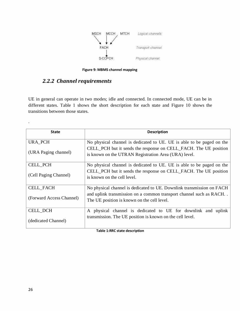
To support MBMS, only 3 new logical channels and one new physical channel have been added to support PtM transmission mode of MBMS in addition to the existing transport channels. For PtP transmission mode of MBMS the existing logical, transport and physical channels can be reused as in unicast. The newly added logical channels are MCCH (MBMS Control Channel), MTCH (MBMS Traffic Channel), and MSCH (MBMS Scheduling Channel), while the newly added MBMS dedicated physical channel is MICH (MBMS notification Indicator). The UEs that have joined the MBMS service will receive the control plane information such as ongoing/upcoming MBMS session details on MCCH. As long as there is no new information on MCCH, UE can stay idle, so it can decrease its power consumption. Whenever the information on MCCH changed, UE will be informed on MICH. User plane information which is the actual MBMS user traffic is provided on MTCH. MSCH carries the scheduling control plane data on MCCH. As it is shown in Figure 9, these logical channels will be mapped to FACH (Forward Access Channel) transport channel and S-CCPCH (Secondary Common Control Physical Channel).
26
Figure 9: MBMS channel mapping
2.2.2 Channel requirements
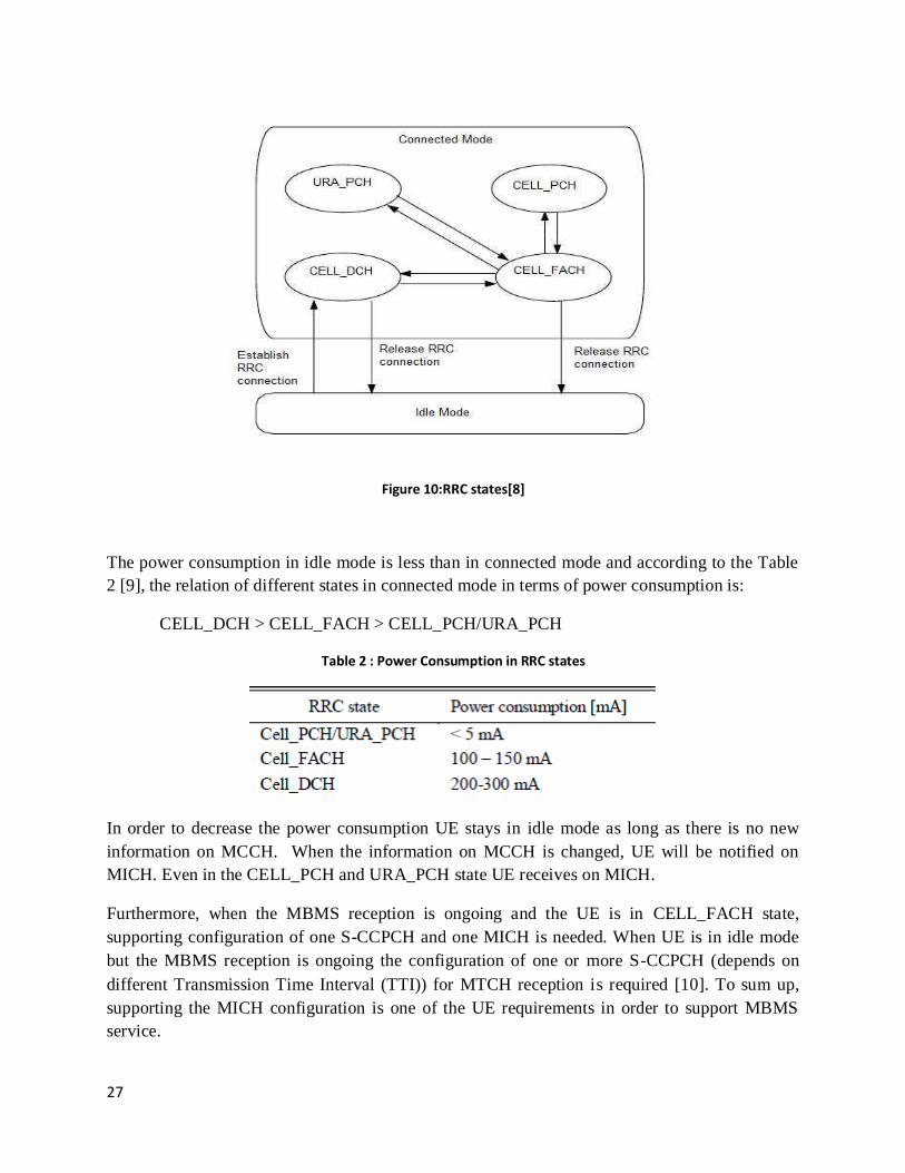
UE in general can operate in two modes; idle and connected. In connected mode, UE can be in different states. Table 1 shows the short description for each state and Figure 10 shows the transitions between those states.
.
State Description
URA_PCH
(URA Paging channel)
No physical channel is dedicated to UE. UE is able to be paged on the CELL_PCH but it sends the response on CELL_FACH. The UE position is known on the UTRAN Registration Area (URA) level.
CELL_PCH
(Cell Paging Channel)
No physical channel is dedicated to UE. UE is able to be paged on the CELL_PCH but it sends the response on CELL_FACH. The UE position is known on the cell level.
CELL_FACH
(Forward Access Channel)
No physical channel is dedicated to UE. Downlink transmission on FACH and uplink transmission on a common transport channel such as RACH. . The UE position is known on the cell level.
CELL_DCH
(dedicated Channel)
A physical channel is dedicated to UE for downlink and uplink transmission. The UE position is known on the cell level.
Table 1:RRC state description
27
Figure 10:RRC states[8]
The power consumption in idle mode is less than in connected mode and according to the Table 2 [9], the relation of different states in connected mode in terms of power consumption is:
CELL_DCH > CELL_FACH > CELL_PCH/URA_PCH
Table 2 : Power Consumption in RRC states
In order to decrease the power consumption UE stays in idle mode as long as there is no new information on MCCH. When the information on MCCH is changed, UE will be notified on MICH. Even in the CELL_PCH and URA_PCH state UE receives on MICH.
Furthermore, when the MBMS reception is ongoing and the UE is in CELL_FACH state, supporting configuration of one S-CCPCH and one MICH is needed. When UE is in idle mode but the MBMS reception is ongoing the configuration of one or more S-CCPCH (depends on different Transmission Time Interval (TTI)) for MTCH reception is required [10]. To sum up, supporting the MICH configuration is one of the UE requirements in order to support MBMS service.
28
Besides that, the UE does not need to be able to receive multiple MBMS Services simultaneously. Based on the UE limitation on memory and Picture-in-Picture (PiP) capability they may or may not support the parallel reception of MBMS and unicast.
UEs that are incapable of supporting parallel reception of MBMS on MTCH must be notified about start of the new service. Upon this notification, the user is informed that a new service has started and thus enables the user to choose between the existing service session and the new incoming one. More details of Technical specification of UE are out of the scope of this thesis work.
2.2.3 PtP and PtM bearer realization
PtM bearer type indicates MBMS data delivery all the way down to the users in the cell through the common radio channel. MBMS broadcast and multicast mode described in Section 2.3.1 use this bearer type. PtP bearer type indicates MBMS data delivery to the users through the dedicated channel for each user. Only multicast mode of MBMS uses PtP bearer type. Usually operators are the ones who decide whether it is more economic for them to use PtP or PtM bearer. Nevertheless, on the network side, in order to be able to choose between PtP and PtM channel type for a specific MBMS service, apart from the available radio resources information, the network needs to know about the number of interested users in a cell. Once the decision is made, it should be also possible to switch between broadcast and multicast mode if the number of users changes. [7][2]
2.2.3.1 Counting mechanism
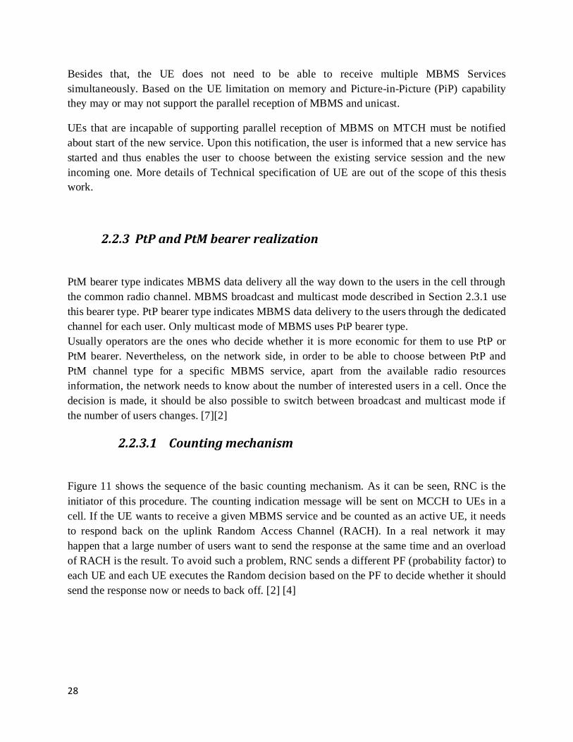
Figure 11 shows the sequence of the basic counting mechanism. As it can be seen, RNC is the initiator of this procedure. The counting indication message will be sent on MCCH to UEs in a cell. If the UE wants to receive a given MBMS service and be counted as an active UE, it needs to respond back on the uplink Random Access Channel (RACH). In a real network it may happen that a large number of users want to send the response at the same time and an overload of RACH is the result. To avoid such a problem, RNC sends a different PF (probability factor) to each UE and each UE executes the Random decision based on the PF to decide whether it should send the response now or needs to back off. [2] [4]
29
Figure 11: Counting procedure
The result of the counting procedure will be used for choosing between PtP and PtM bearer. If the resulting number of interested users does not reach the predefined minimum required number of users within a cell for PtM, the network will select the PtP radio bearer for a given MBMS service for that particular cell. In the explained counting mechanism, as the bearer type selection is only based on the number of interested users and downlink transmission power in BSs is not considered, this may lead to waste of valuable power resources. Therefore, other parameters such as users’ distances from the BS and their QoS/QoE requirements need to be taken into account.[4]
2.3 MBMS bearer service
As the term Multimedia Broadcast Multicast Service implies, MBMS can operate in both broadcast and multicast mode. For both modes, UE needs to show its interest for receiving the service by local reception activation of the service in broadcast mode and, “joining” to the particular MBMS service in multicast mode. With use of broadcast or multicast mode, the same data which is supposed to be sent to different UEs will be transmitted from SGSN to RNC only once even if there will be hundreds of UEs interested to receive it. In this way, the amount of data within the network will be decreased and thereby the efficient use of radio resources is feasible. Broadcast/Multicast service sent to UE may consist of one or several broadcast/multicast sessions.[5]. In the following section more details of MBMS modes is provided.
2.3.1 Broadcast and Multicast mode
In MBMS broadcast mode, MBMS data will be sent to all the UEs located in the MBMS area through a common channel. A particular UE may experience packet loss but there is no feedback sent by UE in broadcast mode. As broadcast is a unidirectional point to multi point transmission
30
through a common radio channel, it makes more efficient use of the radio resources. MBMS operating in broadcast mode is similar to the traditional broadcast technologies such as DVB-H [4]. In multicat mode of MBMS service which is the unidirectional point to point/point to multipoint connection, a UE that is interested in receiving a MBMS service needs to “subscribe” for the particular service and has to “join” the corresponding multicast group to be able to receive the data. Then, in contrast to broadcast mode, MB-SC will be informed about the active UE within the MBMS area. The membership functionality of BM-SC which has been explained in section 2.1.1 is only valid for this mode. When there are just a few users interested in a particular MBMS service within a cell, broadcast mode is not recommended. In other words, multicast mode is useful when there are not a large number of users in the cell interested for a given MBMS service. At the same time, when there are several concurrent MBMS services the resource optimal allocation of users to MBMS bearers is a challenging problem, as shown in [11][12].
2.4 MBMS user services
MBMS User Service uses the MBMS delivery methods to deliver MBMS content to end user through MBMS bearer service. For any MBMS user service, either operators or BM-SC decides for suitable bearer type. When any of them selected, it is not possible to change the bearer during the transmission. But MBMS user service can consist of a number of streams and each stream can be delivered using a different bearer type. Note that some UEs may not be capable of receiving the streams belonging to one MBMS service on several bearer types. Therefore, according to 3GPP standard, using different bearer type for delivering the streams related to the same MBMS service is not recommended [13]. MBMS user service provides two different delivery methods, MBMS Downloading and MBMS streaming. These two methods are suitable for different purposes. The downloading method is needed for reliable delivery of MBMS content, such as delivering a magazine. The streaming method is preferred for delivering real time data, such as video clips. More about delivery methods is discussed in the following section.
2.4.1 MBMS Delivery methods
If for example a magazine is going to be delivered using MBMS service, it will be sent as a file using download method and will be stored locally in the end user’s device. File transmission will start when UE registers for the download service. UE may be notified about the newly available content in its local file system in form of notification message when the transmission is done.
31
File delivery is done using FLUTE (File Delivery over Unidirectional Transport) protocol. The large file may be fragmented and each fragment will be sent via UDP session with FLUTE header. On the receiver side all the fragments related to a single file will be re assembled If a TV program is going to be delivered using MBMS service, it will be sent using the streaming method. In general, streaming method is suitable for continuous data and media stream delivery and it transmits data using RTP (Real Time Protocol) over UDP. UE will join to a MBMS streaming session and can leave the session even before session termination. All the needed codec information will be communicated through MBMS announcement phase.
2.4.2 Packet error recovery scheme
In case of receiving a corrupted file, UE will try to recover either by the use of Rapid Tornado Forward Error Correction (Raptor FEC) technique or through two MBMS associated delivery procedures called File Repair and Reception Reporting. In the case of FEC, the receiver receives the data encoded in a redundant way and therefore it can correct some number of missing parts without any interaction with the server. In networks where retransmission of the data is expensive, FEC is a suitable solution. This is because the receiver will try to auto correct the packet received in error without any need for retransmitting the data again. In case of a large file which needs to be fragmented, Raptor Codes are used to encode each fragment into limitless number of symbols, and for each fragment of the file, an FEC frame with multiple symbols will be generated. In case retransmission is needed, the correct file will be broadcast or multicast to all of the UEs that were participating in the previous transmission regardless of the fact that some may have received the data correctly in the previous session. MBMS Session Identity is an element sent by MB-SC to indicate if the session is repeated or not. In File Repair procedure, at the end of the session UE will see if the received file is corrupted or not. If it is corrupted, it will ask the repair server for the repaired file via unicast bearer. This may result in a large number of requests from different UEs, and could lead to congestion on the uplink and thereby overload on downlink when server tries to respond to the requests. Besides that, the server may crash due to the large number of received requests. Therefore, each UE needs to wait for a back-off time before sending requests. If the server is overloaded with requests it can redirect the request to another server. Reception report is sent by UE as a confirmation of file reception through unicast bearer. BM-SC uses this report for charging the UE based on correct reception of files. UE will wait for a random period of time before sending the report for the same reason as explained above.

32
FEC is best suited for streaming real time data as it can auto correct without the need for retransmission. Reception report can also be used while streaming real time data to provide reception statistics to the server [13]. For downloading cached files any of the three recovery mechanisms that were discussed above can be utilized.
33
Chapter 3
Technological feasibility
This section discusses about the various advancements in the RAN, and the necessary UE technology requirements, which may make eMBMS deployment technologically feasible.
3.1 RAN technology advancements since 3G
Since the time of 3G, there have been many changes in the area of radio access network (RAN) technology. 3GPP study groups constantly release new patches to improve the performance of RAN. In this section we discuss MBMS for LTE networks, namely, eMBMS, and two major improvements to MBMS; MBSFN and HSPA+.
3.1.1 eMBMS architecture
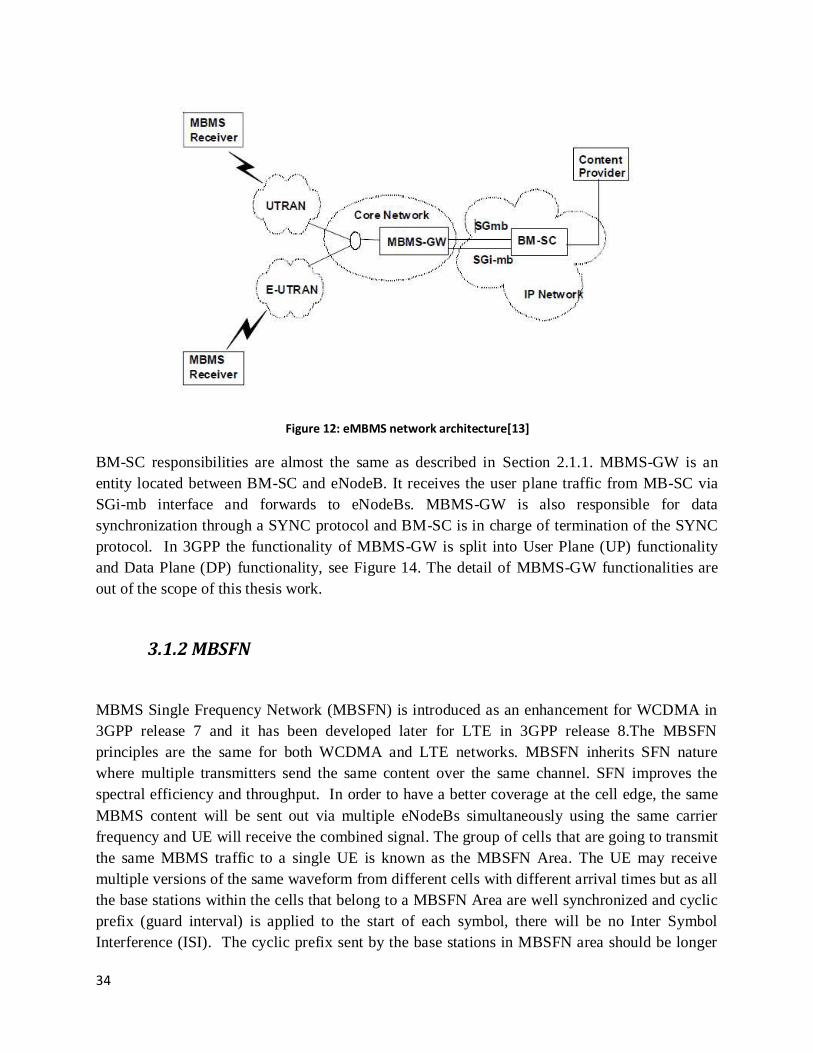
Long Term Evolution (LTE) is defined in 3GPP standard release 8 and enhanced MBMS (eMBMS) was supposed to be part of the release, however it was moved to release 9. With respect to the MBMS principles introduced originally in release 6, two major improvements are expected by introducing LTE: better coverage at the cell edge and more efficient use of spectrum. These important improvements are achieved by taking advantage of Orthogonal Frequency Division Multiplexing (OFDM) modulation in physical layer of LTE and through the use of single frequency networks (SFN) for MBMS. As figure 12 shows, in LTE network, in order to support MBMS with minimum impact to the existing network architecture, MBMS Media Gateway (MBMS-GW) in core network is added as a new element, and similar to 3G networks BM-SC is used in the IP network.
34
Figure 12: eMBMS network architecture[13]
BM-SC responsibilities are almost the same as described in Section 2.1.1. MBMS-GW is an entity located between BM-SC and eNodeB. It receives the user plane traffic from MB-SC via SGi-mb interface and forwards to eNodeBs. MBMS-GW is also responsible for data synchronization through a SYNC protocol and BM-SC is in charge of termination of the SYNC protocol. In 3GPP the functionality of MBMS-GW is split into User Plane (UP) functionality and Data Plane (DP) functionality, see Figure 14. The detail of MBMS-GW functionalities are out of the scope of this thesis work.
3.1.2 MBSFN
MBMS Single Frequency Network (MBSFN) is introduced as an enhancement for WCDMA in 3GPP release 7 and it has been developed later for LTE in 3GPP release 8.The MBSFN principles are the same for both WCDMA and LTE networks. MBSFN inherits SFN nature where multiple transmitters send the same content over the same channel. SFN improves the spectral efficiency and throughput. In order to have a better coverage at the cell edge, the same MBMS content will be sent out via multiple eNodeBs simultaneously using the same carrier frequency and UE will receive the combined signal. The group of cells that are going to transmit the same MBMS traffic to a single UE is known as the MBSFN Area. The UE may receive multiple versions of the same waveform from different cells with different arrival times but as all the base stations within the cells that belong to a MBSFN Area are well synchronized and cyclic prefix (guard interval) is applied to the start of each symbol, there will be no Inter Symbol Interference (ISI). The cyclic prefix sent by the base stations in MBSFN area should be longer
35
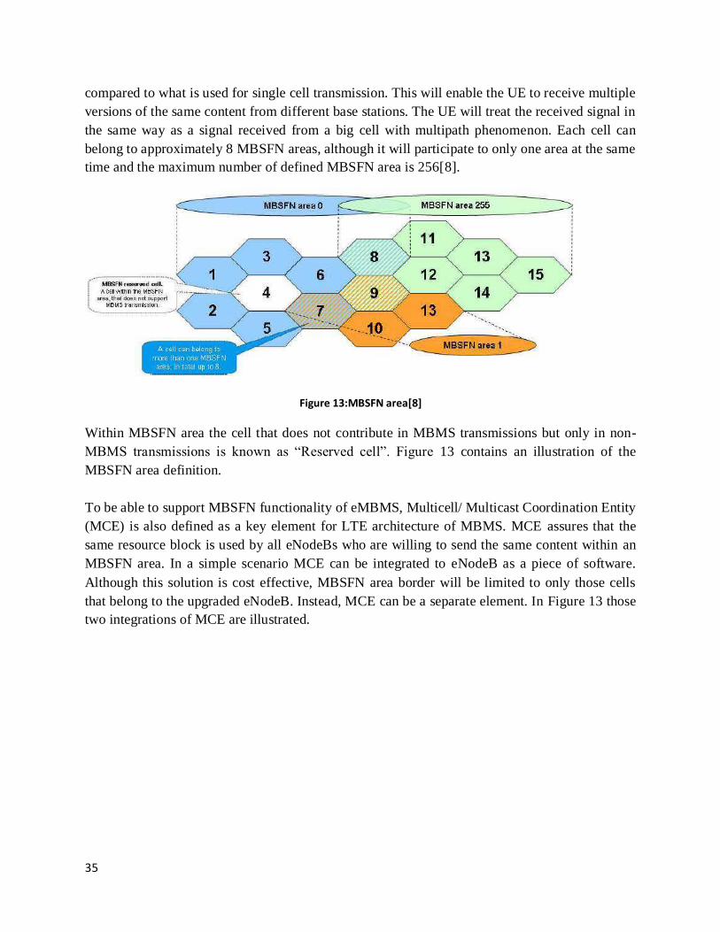
compared to what is used for single cell transmission. This will enable the UE to receive multiple versions of the same content from different base stations. The UE will treat the received signal in the same way as a signal received from a big cell with multipath phenomenon. Each cell can belong to approximately 8 MBSFN areas, although it will participate to only one area at the same time and the maximum number of defined MBSFN area is 256[8].
Figure 13:MBSFN area[8]
Within MBSFN area the cell that does not contribute in MBMS transmissions but only in non-MBMS transmissions is known as “Reserved cell”. Figure 13 contains an illustration of the MBSFN area definition. To be able to support MBSFN functionality of eMBMS, Multicell/ Multicast Coordination Entity (MCE) is also defined as a key element for LTE architecture of MBMS. MCE assures that the same resource block is used by all eNodeBs who are willing to send the same content within an MBSFN area. In a simple scenario MCE can be integrated to eNodeB as a piece of software. Although this solution is cost effective, MBSFN area border will be limited to only those cells that belong to the upgraded eNodeB. Instead, MCE can be a separate element. In Figure 13 those two integrations of MCE are illustrated.
36
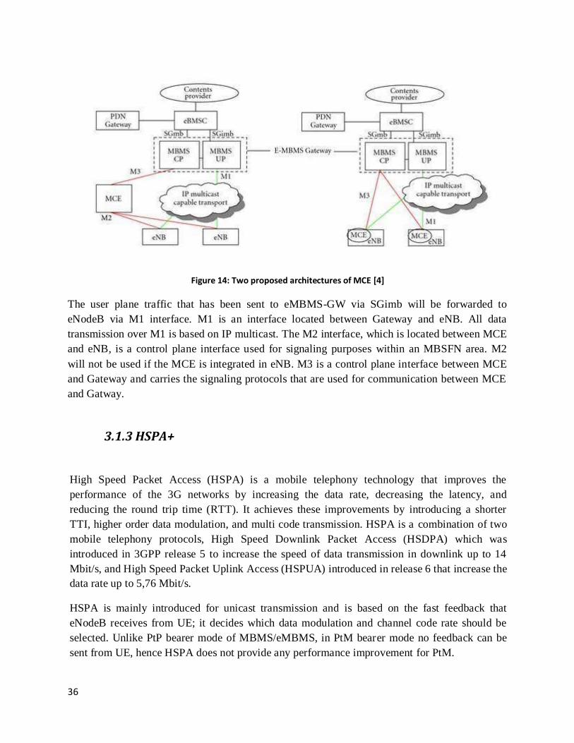
Figure 14: Two proposed architectures of MCE [4]
The user plane traffic that has been sent to eMBMS-GW via SGimb will be forwarded to eNodeB via M1 interface. M1 is an interface located between Gateway and eNB. All data transmission over M1 is based on IP multicast. The M2 interface, which is located between MCE and eNB, is a control plane interface used for signaling purposes within an MBSFN area. M2 will not be used if the MCE is integrated in eNB. M3 is a control plane interface between MCE and Gateway and carries the signaling protocols that are used for communication between MCE and Gatway.
3.1.3 HSPA+
High Speed Packet Access (HSPA) is a mobile telephony technology that improves the performance of the 3G networks by increasing the data rate, decreasing the latency, and reducing the round trip time (RTT). It achieves these improvements by introducing a shorter TTI, higher order data modulation, and multi code transmission. HSPA is a combination of two mobile telephony protocols, High Speed Downlink Packet Access (HSDPA) which was introduced in 3GPP release 5 to increase the speed of data transmission in downlink up to 14 Mbit/s, and High Speed Packet Uplink Access (HSPUA) introduced in release 6 that increase the data rate up to 5,76 Mbit/s.
HSPA is mainly introduced for unicast transmission and is based on the fast feedback that eNodeB receives from UE; it decides which data modulation and channel code rate should be selected. Unlike PtP bearer mode of MBMS/eMBMS, in PtM bearer mode no feedback can be sent from UE, hence HSPA does not provide any performance improvement for PtM.

37
As an advancement over HSPA, HSPA+ was introduced in Release 7. HSPA+ is also known as evolved HSPA, as it offers increased downlink data rates of up to 168 Mbps to the UE and up to 22 Mbps in the uplink direction, from the UE to the NodeB/eNodeB. This increased throughput is achieved with the use of multiple antennas in receive and transmit directions, also known as MIMO (Multiple-Input-Multiple-Output). Higher modulation techniques such as 64QAM further help in providing high data rates. The throughput rates represent theoretical limits of the data rates, while the actual data rates can be lower. HSPA+ usually provides much higher data rates in really good channel conditions, for e.g. when the UE is very close to the NodeB/eNodeB.
Figure 15 compares the spectral efficiencies for different wireless standards. The introduction of HSPA with MIMO and 64QAM has aided in increasing the data rates. Similarly in the case of LTE, the number of input and output antennas for MIMO has also resulted in increased data rates. CDMA2000 and WiMax are out of scope of this thesis work.
Figure 15 : Spectral efficiency evolution for LTE and UMTS networks [14]
If Dual-Cell HSDPA is used in conjunction with HSPA+, one can achieve data rates close to the theoretical limit of 168 Mbps. Dual-Cell HSDPA is the technique of allowing users to connect to two cells at the same time, thereby providing an opportunity for the UE to double the data rates.
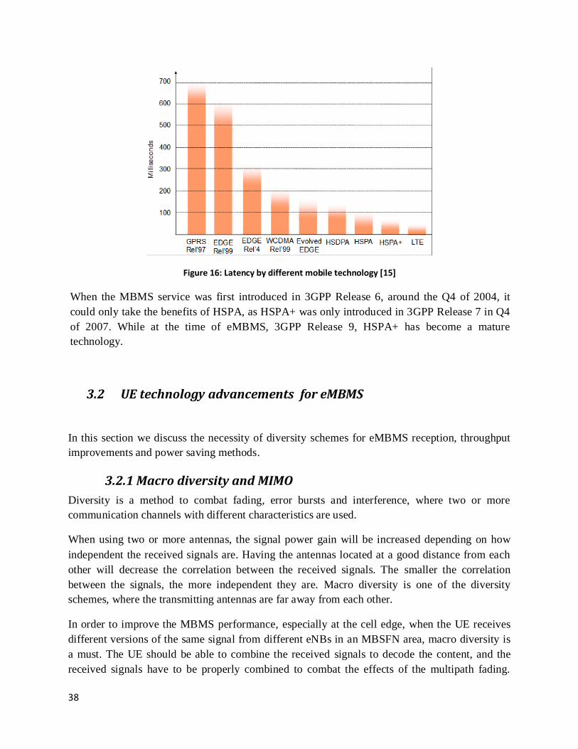
Introducing new mobile technologies had a big improvement in the round trip time in the network. As Figure 16 shows, HSPA + has half the network latency in comparison to WCDMA, and LTE is going to improve the latency even more. Latency improvements are due to improvements in each successive technology, e.g., LTE has a more flat architecture reducing the number of hops. In addition to technology improvements, telecommunication equipment vendors and operators are also continuously adapting their networks to reduce latency.
38
Figure 16: Latency by different mobile technology [15]
When the MBMS service was first introduced in 3GPP Release 6, around the Q4 of 2004, it could only take the benefits of HSPA, as HSPA+ was only introduced in 3GPP Release 7 in Q4 of 2007. While at the time of eMBMS, 3GPP Release 9, HSPA+ has become a mature technology.
3.2 UE technology advancements for eMBMS
In this section we discuss the necessity of diversity schemes for eMBMS reception, throughput improvements and power saving methods.
3.2.1 Macro diversity and MIMO
Diversity is a method to combat fading, error bursts and interference, where two or more communication channels with different characteristics are used.
When using two or more antennas, the signal power gain will be increased depending on how independent the received signals are. Having the antennas located at a good distance from each other will decrease the correlation between the received signals. The smaller the correlation between the signals, the more independent they are. Macro diversity is one of the diversity schemes, where the transmitting antennas are far away from each other.
In order to improve the MBMS performance, especially at the cell edge, when the UE receives different versions of the same signal from different eNBs in an MBSFN area, macro diversity is a must. The UE should be able to combine the received signals to decode the content, and the received signals have to be properly combined to combat the effects of the multipath fading.
39
There are two types of combining that can be used for macro diversity in wireless networks: Selective combining and Soft combining.
With Selective combining, when the UE receives multiple versions of the same signal from different eNBs, it first decodes all the signals in the Radio Link control (RLC) layer, and then calculates the SNR for each version and chooses the version with the best SNR.
With Soft combining which is performed on the physical layer, all the signals received are first combined and then the result will be decoded. The process of combining the received signals can be implemented in various ways. “Equal Gain combining” and “Maximal Ratio combining” are techniques for soft combining. In Equal Gain combining, the UE adds up all the received signals and decodes the result. In Maximal Ratio combining, the UE calculates a weighted sum of the received signals. The weights are decided based on the received SNR.
Simulation results from [9] show that the UE performs significantly better with macro diversity. Simulations have been performed for two different channel profiles, namely, Vehicular A and Pedestrian A types. Vehicular A type channel has more multipath diversity and more jitter, while Pedestrian has less multipath diversity and less jitter. In Vehicular A type channel, soft combining provides 5dB gain, while selective combining provides 3dB gain in comparison with no combining. The study shows that the amount of gain provided by these combining schemes depends on the channel profile, such as Pedestrian A, or Vehicular A. Furthermore, in networks requiring small BLER targets it was shown that there is not much difference in the gains provided by selective and soft combining. This is because networks requiring smaller BLER targets do not require a high SNR value to be able to meet the target, since they allow more packets to be received in error. The power required to reach the BLER target with selective combining is almost equal to the power required with soft combining.
Consequently, depending on the channel conditions one could choose between selective or soft combining. In cells where the channel conditions are similar to the Vehicular A profile, e.g., on highways where the UEs are travelling at higher speeds, it is good to have soft combining. Under channel conditions similar to Pedestrian A, e.g., on the streets in downtown Stockholm where there are no high speed movements, signal quality does not depend on the combining scheme. Nevertheless, since soft combining is more complex to implement, it makes sense to use selective combining in this downtown scenario.
For MBMS, in order to make use of macro diversity, which improves the reception in MBSFN, and also to support HSPA+, UE must be equipped with MIMO technology. MIMO is an old technology introduced in the early 90s, but in mobile telecommunications it is employed only with LTE with the introduction of HSPA+.
40
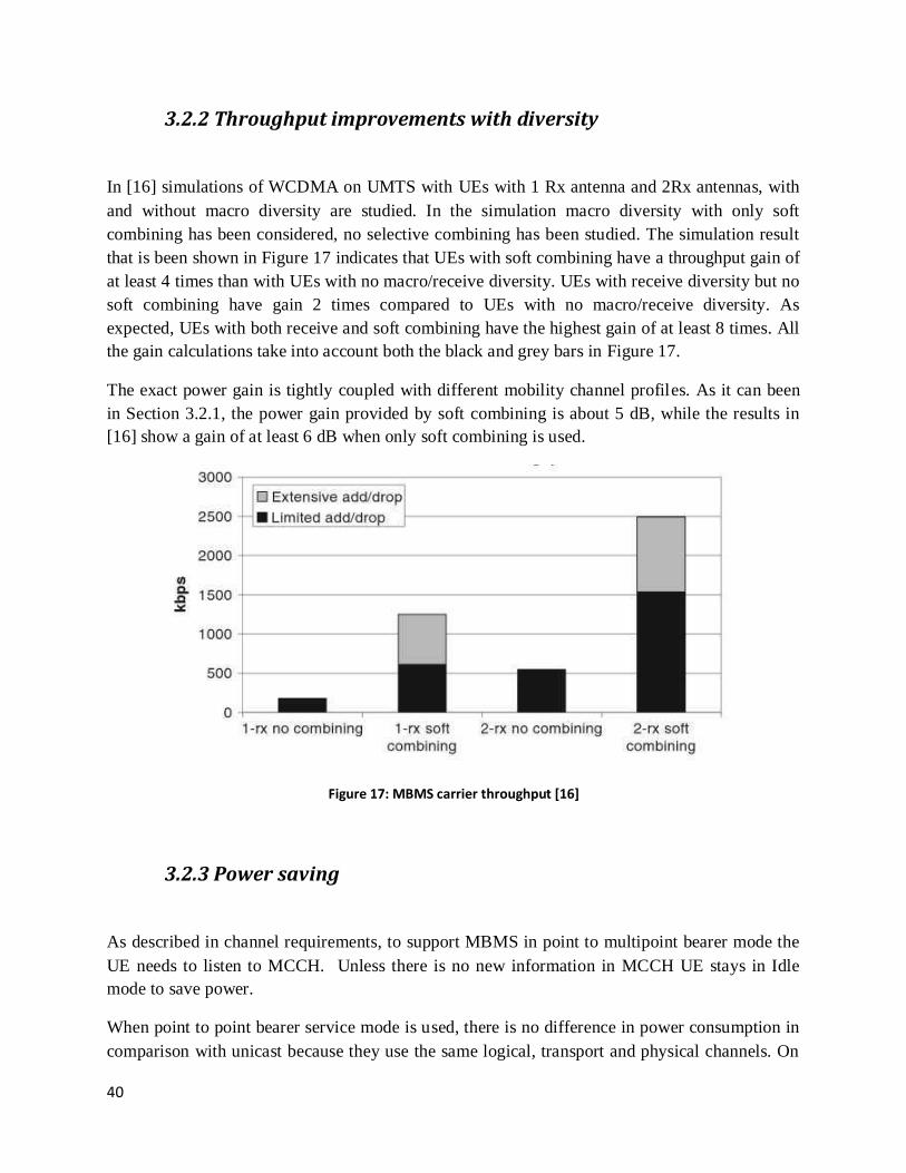
3.2.2 Throughput improvements with diversity
In [16] simulations of WCDMA on UMTS with UEs with 1 Rx antenna and 2Rx antennas, with and without macro diversity are studied. In the simulation macro diversity with only soft combining has been considered, no selective combining has been studied. The simulation result that is been shown in Figure 17 indicates that UEs with soft combining have a throughput gain of at least 4 times than with UEs with no macro/receive diversity. UEs with receive diversity but no soft combining have gain 2 times compared to UEs with no macro/receive diversity. As expected, UEs with both receive and soft combining have the highest gain of at least 8 times. All the gain calculations take into account both the black and grey bars in Figure 17.
The exact power gain is tightly coupled with different mobility channel profiles. As it can been in Section 3.2.1, the power gain provided by soft combining is about 5 dB, while the results in [16] show a gain of at least 6 dB when only soft combining is used.
Figure 17: MBMS carrier throughput [16]
3.2.3 Power saving
As described in channel requirements, to support MBMS in point to multipoint bearer mode the UE needs to listen to MCCH. Unless there is no new information in MCCH UE stays in Idle mode to save power.
When point to point bearer service mode is used, there is no difference in power consumption in comparison with unicast because they use the same logical, transport and physical channels. On

41
the contrary, when PtM bearer service mode is used for MBMS, new channels are needed to support MBMS functionality as mentioned in Section 2.2.1. PtM uses FACH common channel, which does not support fast power control.
The objective of the fast power control is to keep the received signal at the NodeB/eNodeB as close as possible to the required level. This is achieved by adjusting the transmit power of the UE. The NodeB computes a transmit power control command (TPC) using the received signal strength and the required signal strength and sends it to the UE, which updates it’s transmit power accordingly.
Since FACH does not support fast power control, the transmitted power is not updated according to the requirements, instead a constant power is used and therefore the average power is higher than usual.
Use of more than one receive antenna, MIMO, of course, increases the power consumption. Thus, power saving techniques are needed. One way to save power would be to switch off all but one antennas when the receive conditions are good, e.g., when the received signal strength is above a certain threshold. This method is called Rx switching.
42
Chapter 4
Market Feasibility
In this section we discuss various factors, such as, UE evolution, user demands and data usage predictions, which can make the market feasible for eMBMS deployment.
4.1 UE evolution since 3G
Today’s mobile phones are different from the ones that were popular at the time of the introduction of 3G networks and mobile technology has improved in comparison to 2006, when the MBMS was introduced in 3GPP release 6. MBMS can benefit from these improvements and perhaps operators can take advantage of the capabilities of new mobile phone generations for encouraging their customers to consume more media on their mobile phones. The main differences between UEs at the time of 3G vs. 4G are:
At the time of 3G networks, feature phones were more popular than smart phones. A feature phone is a handset with less functionality than a smart phone but more functionality than a normal mobile phone. Feature phones have proprietary operating systems and not all of them support third party applications known as “apps”. Smart phones have a third party operating system such as Android, Windows Mobile, Symbian, BlackBerry. They are all able to run third party applications. This can be a good reason for smart phones to be a better choice for the purpose of MBMS. The MBMS apps can be installed on demand and can be run on most smart phones and can be updated when an update is available. Smart phones running proprietary OSes, like the iOS on an iPhone have a huge application development community who develop similar application for their phones to be able to survive in the market.
In 2007 at the time of 3G networks, the PRADA phone by LG was the first complete touch screen phone introduced to the market. Over the past few years touch screen technology has become more popular with almost all new phones having touch screens nowadays. MBMS can take advantage of touch screen phones where the user can simply play or pause the video stream by only one touch. Besides that, with the touch screen phones there is no need of extra work space for keyboard, hence the screen size can be relatively bigger than on non-touch screen phones and clearly the bigger screen is much more suited for reproducing media.
43
Mobile display resolutions have improved significantly in the recent years. E.g., the Nokia N97, which was popular in 2008, had a screen resolution of 360x640, while the IPhone4s, which was popular in 2012, has a much higher screen resolution of 640x960. The Samsung Galaxy S4, introduced in 2013 has an HD resolution of 1920x1080. Also, newer phones have more memory capacity, more processing power and faster CPUs which help in making media playback smoother and more enjoyable.
Mobile screen sizes have increased from about 2” in 2007 to 5” in 2012 and there are even tablets with 10” screens. This is another catalyst to consume more media on latest phones with larger screens, in turn, increasing media streaming to the mobile phone. Increasing screen sizes and resolutions in turn increase power consumption. But the industry has come up with better screen technologies, such as AMOLED, Super AMOLED, Super AMOLED Advanced, etc., than existing LCD technology to counter the issue of screen power consumption.
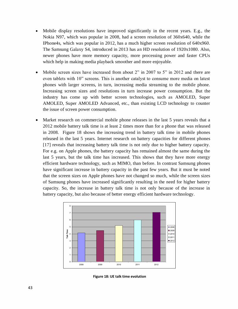
Market research on commercial mobile phone releases in the last 5 years reveals that a 2012 mobile battery talk time is at least 2 times more than for a phone that was released in 2008. Figure 18 shows the increasing trend in battery talk time in mobile phones released in the last 5 years. Internet research on battery capacities for different phones [17] reveals that increasing battery talk time is not only due to higher battery capacity. For e.g. on Apple phones, the battery capacity has remained almost the same during the last 5 years, but the talk time has increased. This shows that they have more energy efficient hardware technology, such as MIMO, than before. In contrast Samsung phones have significant increase in battery capacity in the past few years. But it must be noted that the screen sizes on Apple phones have not changed so much, while the screen sizes of Samsung phones have increased significantly resulting in the need for higher battery capacity. So, the increase in battery talk time is not only because of the increase in battery capacity, but also because of better energy efficient hardware technology.
0
1
2
3
4
5
6
7
8
2008 2009 2010 2011 2012
Talk
Tim
e
2008
2009
2010
2011
2012
Figure 18: UE talk time evolution
44
4.2 User demand
Various factors that affect user behavior regarding media streaming on the phone are listed in this section. A survey is used as the methodology to study the listed factors. The results of the survey are then analyzed to highlight those factors that operators need to consider when deploying MBMS.
4.2.1 User expectations for mobile media streaming
The following are some of the factors that we think are important from a user perspective, when it comes to media streaming. Some of these factors can be technical in nature and some could be personal factors that depend on the personality of the user. The factors listed below have been taken into account for the survey structure.
4.2.1.1 Quality of Internet connection
Streaming media from the operator to the UE requires fast and consistent internet connection. Operators need to ensure that there are no sudden drops in quality of the Internet connection. Loss of good internet connectivity can interrupt the continuous streaming of media, which can in turn reduce user motivation to utilize the MBMS service.
Of course, users do not want the introduction of the MBMS service to cause degradation of other existing services such as SMS, MMS, calls etc.
4.2.1.2 UE battery consumption
Usually UE battery is the bottleneck in introducing new services. So in order to make the introduction of MBMS service successful, it is important to keep the effect on battery usage minimal. Of course, media streaming will increase battery usage, but if the users do not feel much difference while using MBMS in comparison to while not using it, they will be more eager to use the service. Otherwise the users would prefer to conserve the battery for calls/SMS.
45
4.2.1.3 UE screen resolution
Screen size and resolution are important in order to have a good experience while watching media. This can especially be true while watching media on the phone. Since, mobile sets tend to be smaller; increasing the quality of experience on mobiles can be harder on mobiles than on TVs. Moreover the screen size and resolution of mobiles cannot become much bigger than what it is today; nevertheless we do not expect this to be a big concern among users.
4.2.1.4 Interests
Interesting live events that users don’t want to miss (e.g., football world cup finals) when they do not have access to media players which can quickly stream live events on big screens, such as TV, computers etc. are a significant factor for driving online streaming on mobile phones. People can be interested in different live events, from Football matches and Live TV shows such as American Idol, Eurovision, to latest and hottest political developments. Therefore, operators need to investigate and find out about these big events, how popular the events are, and what is the target audience (based on their previous streaming history) for the events.
4.2.1.5 Economic status
Mobile media streaming is much more enjoyable on a new phone with latest technology and with access to a fast internet connection. Users may need to upgrade their phones, and have to subscribe to faster internet connections and MBMS services from the operator, both of which cost extra money. People with lower level of income may not be able to afford newer phones and latest technology. So, unless the operators and mobile vendors keep the cost low enough for these users to be able to afford it, these users should not be considered as a target for MBMS services.
4.2.1.6 General technical awareness
Deploying newer technology always depends on the willingness of the users to start using it and also needs some effort to develop an understanding of how to use it. Thus, complicated setup instructions or installing of new applications could lead some users to ignore the new technology. Therefore, operators who wish to introduce the MBMS service to their customers should keep setup of the service simple and also they should push mobile application developers to make user friendly applications for deploying MBMS service.
46
4.2.1.7 Spare Time
Some users spend a lot of time traveling during the day, such as to and from work or university. These users can be a good target for MBMS service. It might be a good idea for operators to introduce the service along the path that users commute during the rush hour. Bigger cities usually have huge traffic towards the city center, universities, and other industrial suburbs during the rush hours. Nevertheless, traffic from this kind of users can be bursty, peaking around the rush hour traffic. Thus, operators could use the download mode of MBMS service, explained in section 2.1.4.1 to push the most popular contents, such as popular videos on YouTube or the latest and hottest news, to the user’s mobiles during non-rush hours. In this way, users can reproduce the content without streaming online from the operator, which can reduce the rush hour traffic congestion. Of course, this cannot be a solution for streaming of real time events, for example, for Football matches or election result updates. Therefore the operator needs to be smart in using the general trend of what content is currently popular and also personal history of the user, what he/she has viewed previously and what is the current interest of the user.
Besides, there are the users who are traveling by bus or train from one city to another with a lot of idle time and need to entertain themselves. They can be a good target for the operators to introduce the MBMS service to. Thus the highways and rail roads between two cities would be a good place for operators to enable the MBMS service. These users usually will be traveling at high speed and therefore the operators need to make sure that the quality of the internet connection does not deteriorate at high speed. Of course, nowadays some of the newer buses/trains are equipped with WiFi on board, but until this become commonplace the operators need to secure this need also.
4.2.2 Survey results
The methodology that was used for this section is a survey by asking people chosen at random ages, genders, and from various backgrounds such as occupations, interests and social status. The survey was taken in November 2012, in Stockholm from about 200 random people on the subway between central Stockholm and Kista on a Monday evening and on an inter-city train between Stockholm and Linköping on a Thursday morning. The probability sampling method used for sample selection is “Stratified sampling” where the sampling population is divided to different sub populations based on gender and age. The purpose of the survey is to evaluate the most significant factors that were listed in Section 4.2.
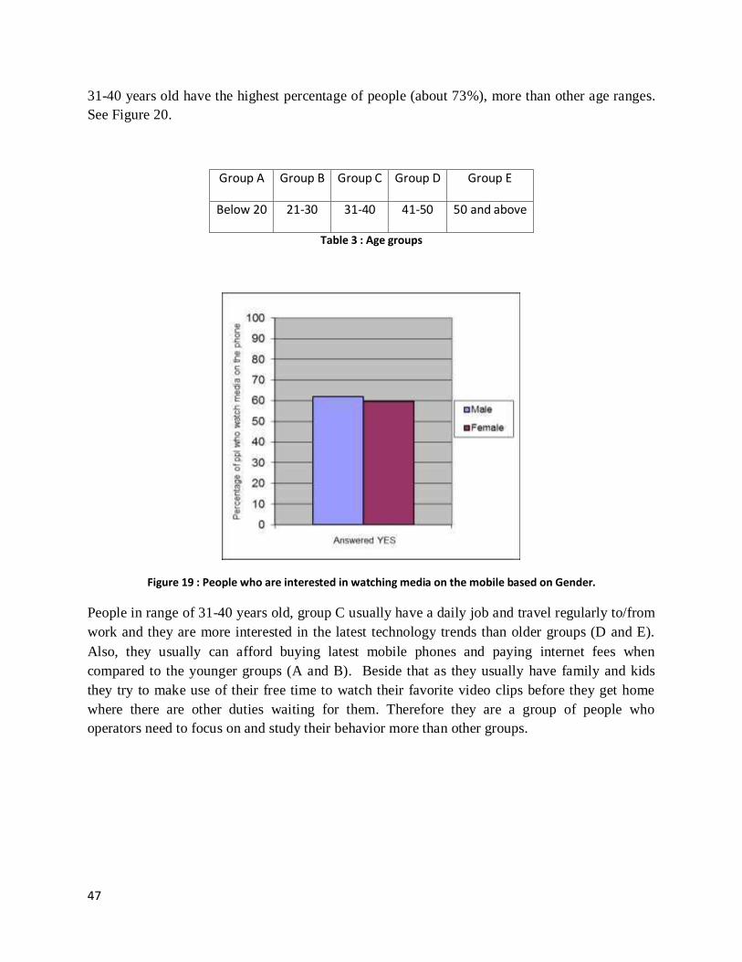
Contrary to popular perception, the survey results show that men are only slightly more interested in watching media on their phones than women. See Figure 19. Among those people who answered YES to “Do you usually watch media on your phone?” the ones who are between
47
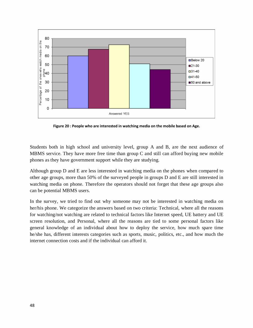
31-40 years old have the highest percentage of people (about 73%), more than other age ranges. See Figure 20.
Group A Group B Group C Group D Group E
Below 20 21-30 31-40 41-50 50 and above
Table 3 : Age groups
Figure 19 : People who are interested in watching media on the mobile based on Gender.
People in range of 31-40 years old, group C usually have a daily job and travel regularly to/from work and they are more interested in the latest technology trends than older groups (D and E). Also, they usually can afford buying latest mobile phones and paying internet fees when compared to the younger groups (A and B). Beside that as they usually have family and kids they try to make use of their free time to watch their favorite video clips before they get home where there are other duties waiting for them. Therefore they are a group of people who operators need to focus on and study their behavior more than other groups.
48
Figure 20 : People who are interested in watching media on the mobile based on Age.
Students both in high school and university level, group A and B, are the next audience of MBMS service. They have more free time than group C and still can afford buying new mobile phones as they have government support while they are studying.
Although group D and E are less interested in watching media on the phones when compared to other age groups, more than 50% of the surveyed people in groups D and E are still interested in watching media on phone. Therefore the operators should not forget that these age groups also can be potential MBMS users.
In the survey, we tried to find out why someone may not be interested in watching media on her/his phone. We categorize the answers based on two criteria: Technical, where all the reasons for watching/not watching are related to technical factors like Internet speed, UE battery and UE screen resolution, and Personal, where all the reasons are tied to some personal factors like general knowledge of an individual about how to deploy the service, how much spare time he/she has, different interests categories such as sports, music, politics, etc., and how much the internet connection costs and if the individual can afford it.
49
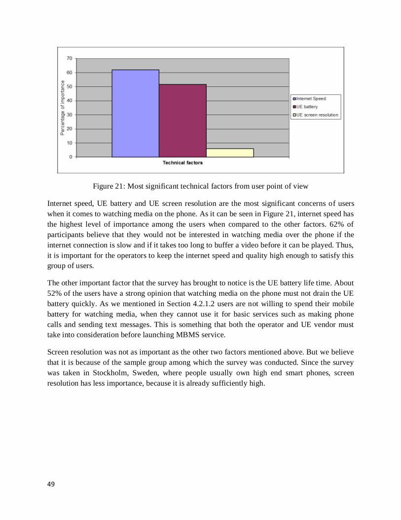
Figure 21: Most significant technical factors from user point of view
Internet speed, UE battery and UE screen resolution are the most significant concerns of users when it comes to watching media on the phone. As it can be seen in Figure 21, internet speed has the highest level of importance among the users when compared to the other factors. 62% of participants believe that they would not be interested in watching media over the phone if the internet connection is slow and if it takes too long to buffer a video before it can be played. Thus, it is important for the operators to keep the internet speed and quality high enough to satisfy this group of users.
The other important factor that the survey has brought to notice is the UE battery life time. About 52% of the users have a strong opinion that watching media on the phone must not drain the UE battery quickly. As we mentioned in Section 4.2.1.2 users are not willing to spend their mobile battery for watching media, when they cannot use it for basic services such as making phone calls and sending text messages. This is something that both the operator and UE vendor must take into consideration before launching MBMS service.
Screen resolution was not as important as the other two factors mentioned above. But we believe that it is because of the sample group among which the survey was conducted. Since the survey was taken in Stockholm, Sweden, where people usually own high end smart phones, screen resolution has less importance, because it is already sufficiently high.
50
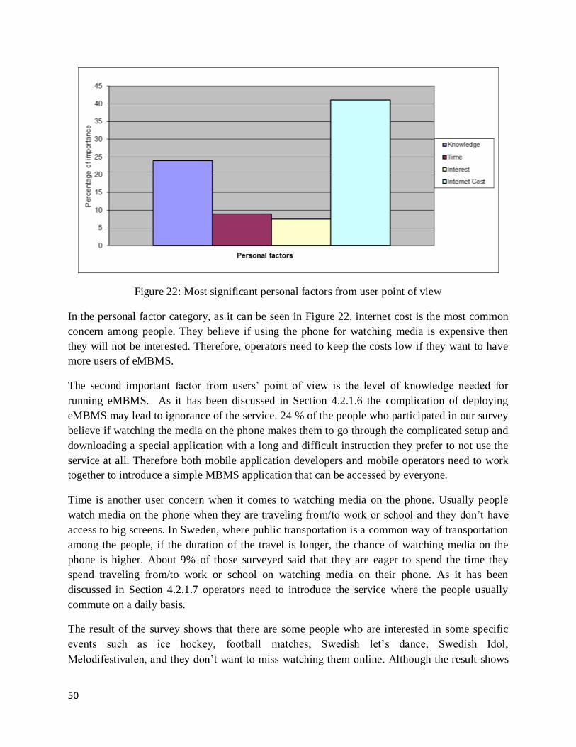
Figure 22: Most significant personal factors from user point of view
In the personal factor category, as it can be seen in Figure 22, internet cost is the most common concern among people. They believe if using the phone for watching media is expensive then they will not be interested. Therefore, operators need to keep the costs low if they want to have more users of eMBMS.
The second important factor from users’ point of view is the level of knowledge needed for running eMBMS. As it has been discussed in Section 4.2.1.6 the complication of deploying eMBMS may lead to ignorance of the service. 24 % of the people who participated in our survey believe if watching the media on the phone makes them to go through the complicated setup and downloading a special application with a long and difficult instruction they prefer to not use the service at all. Therefore both mobile application developers and mobile operators need to work together to introduce a simple MBMS application that can be accessed by everyone.
Time is another user concern when it comes to watching media on the phone. Usually people watch media on the phone when they are traveling from/to work or school and they don’t have access to big screens. In Sweden, where public transportation is a common way of transportation among the people, if the duration of the travel is longer, the chance of watching media on the phone is higher. About 9% of those surveyed said that they are eager to spend the time they spend traveling from/to work or school on watching media on their phone. As it has been discussed in Section 4.2.1.7 operators need to introduce the service where the people usually commute on a daily basis.
The result of the survey shows that there are some people who are interested in some specific events such as ice hockey, football matches, Swedish let’s dance, Swedish Idol, Melodifestivalen, and they don’t want to miss watching them online. Although the result shows
51
there are only 7.5 % of the people who are loyal followers of some events, at the time of those events this number will be increased as the news around the events will be spread and everyone will talk about it here and there. Therefore operators need to be aware of all upcoming events and try to provide the service with good quality at the right time to not disappoint the user.
From a user point of view, the survey has shown that internet speed, internet cost, UE battery and the complexity of setting up the MBMS services on the UE are the most important factors that affect the popularity of using MBMS. Hence it is important for the operator to take these factors into consideration while introducing the MBMS service.
4.3 Data explosion since 3G
According Mobile Broadband Explosion, Rysavy Research, September 2011, 3G and 4G connection speeds in 2014 can reach up to and more than 1 Gbps[14]. See Figure 23.
Figure 21: Data rate evolution for LTE and HSPA technologies [14]
Furthermore, Active mobile-broadband subscriptions have increased steeply in the last decade with almost a 40% increase in 2011 compared to 2010. More than half the population in the developed world (e.g., Western Europe or North America) has access to mobile-broadband as seen in Figure 24. Since 2007 (at the time of 3G) the penetration of mobile-broadband subscriptions in the world has seen almost a 6 time increase. Even in the developing world, we can see a steep increase in the number of mobile-broadband subscriptions.

52
Figure 22: Active mobile broadband subscriptions [18]
Increasing both mobile subscriptions and mobile data rates will of course lead to an explosion in mobile data traffic. A research done by Cisco regarding the mobile data traffic forecast for the next four years predicts this data explosion. As it can be seen in Figure 25, Mobile video holds the most potential growth trajectory. The next in line is Mobile Web/Data with a predicted growth of more than 400% in the next four years.
Figure 23: Mobile traffic growth by type of traffic [19]
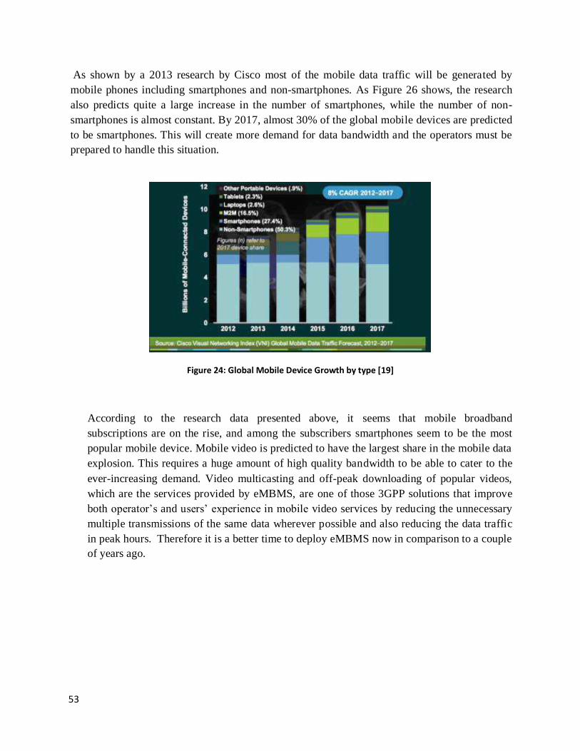
53
As shown by a 2013 research by Cisco most of the mobile data traffic will be generated by mobile phones including smartphones and non-smartphones. As Figure 26 shows, the research also predicts quite a large increase in the number of smartphones, while the number of non-smartphones is almost constant. By 2017, almost 30% of the global mobile devices are predicted to be smartphones. This will create more demand for data bandwidth and the operators must be prepared to handle this situation.
Figure 24: Global Mobile Device Growth by type [19]
According to the research data presented above, it seems that mobile broadband subscriptions are on the rise, and among the subscribers smartphones seem to be the most popular mobile device. Mobile video is predicted to have the largest share in the mobile data explosion. This requires a huge amount of high quality bandwidth to be able to cater to the ever-increasing demand. Video multicasting and off-peak downloading of popular videos, which are the services provided by eMBMS, are one of those 3GPP solutions that improve both operator’s and users’ experience in mobile video services by reducing the unnecessary multiple transmissions of the same data wherever possible and also reducing the data traffic in peak hours. Therefore it is a better time to deploy eMBMS now in comparison to a couple of years ago.
54
Chapter 5
Conclusion
As it has been discussed in Chapter 3, HSPA+ and LTE provide higher data rates and less latency, so they are more suitable for media streaming both live and on-demand. Also, the utilization of diversity schemes and MIMO provide power efficient reception with higher throughput especially in an MBSFN area. Thus, from a technology perspective, it is more feasible to deploy MBMS service in LTE networks than in 3G networks.
As it has been discussed in Chapter 4, advancements in UE, such as the introduction of smart phones with bigger screens and better resolutions have increased user motivation for media streaming on phones, which has resulted in increasing number of subscriptions and consequently an explosion in mobile video data in the networks. To overcome this substantial increase in network resource needs, the operators could deploy MBMS to make efficient use of their networks. Survey results show that the internet speed, internet cost, UE battery and complexity of setting up the service are the most important factors from the user point of view for streaming media.
It has been shown that technology advancements and UE evolution can dissolve user concerns regarding internet speed and UE battery
For the internet cost and complexity of setting up the service, the operator who wants to deploy MBMS must make sure that
o Cost of the service is low enough for users to be able to afford it
o Installation of the service is simple enough for all the different types of users
As a conclusion we can say that it is more feasible to deploy MBMS services from both market and technology perspectives now than at the time of 3G.
55
Future work As concluded above, it is a better time to deploy MBMS now, than during the time of 3G from the perspective of user demands and technology advancements. However, the thesis does not quantify the benefits of deploying MBMS for operators and users.
Future work could be
o Investigation of how viable the service is in terms of cost required to deploy MBMS, and also how much added value MBMS provides to the operators.
o Feasibility analysis to find out if there are enough use-cases (events) for the operator to provide the service. The number of different live events and their popularity among various target audiences to know if MBMS deployment is financially feasible.
o Study of the usage patterns in different regions and different times to understand where and when the service must be available, e.g., along the paths towards the city center during rush hour.
Besides, content providers, who are part of the MBMS service chain (apart from Users and Operators), have not been taken in to account in this thesis. The behavior of content providers could be yet another subject of future work, as their business models may affect the viability of MBMS deployment for the operators and therefore affect the users consequently.
56
References [1] Overview of 3GPP Release 6 V0.1.1 (2010-02)
[2] F. Hartung, U.Horn, J. Huschke, M. Kampmann, T.Lohmar, “MBMS—IP Multicast/Broadcast in 3G Networks,” International Journal of Digital Multimedia Broadcasting, vol. 2009, Article ID 597848, 2009. doi:10.1155/2009/597848.
[3] M. Annamalai ,”Multimedia Broadcast Multicast Service (MBMS) in GSM based Wireless”, T-mobile, ”[online at http://www.slideshare.net/Garry54/multimedia-broadcast-multicast-service-
mbms-in-gsm-based, accessed 22-11-2013]”
[4] Z. Yetgin, T.Çelik,” Efficient progressive downloading over multimedia broadcast multicast service”, Computer Networks, 56(2), Feb. 2012, pp.533-547.
[5] A. Soares, A. Correia, J. Silva, N. Souto,”UE Counting Mechanism for MBMS Considering PtM Macro Diversity Combining Support in UMTS Networks”, in Proc. of IEEE Ninth International Symposium on Spread Spectrum Techniques and Application, Manaus-Amazon, Brazil, 2006, pp. 361-365.
[6] A. Alexiou, C. Bouras, E. Rekkas,” A Novel Power Counting Mechanism for Enhanced MBMS Performance in UMTS Networks", in Proc. of IFIP conference on Wireless and Mobile networking, Toulouse, France, Oct. 2008
[8] 3GPP TS 26.346 version 9.3.0 Release 9.
[9] K.Aho, T. Ristaniemi, V.Haikola, “System Level Performance of Multimedia Broadcast Multicast Service (MBMS) with Macro Diversity”, in Proc. of IEEE Wireless Communications and Networking, Hong Kong, 2007.
[10] ETSI TS 125 346 V10.0.0
[11] V. Vukadinovic , G. Dán, “Multicast Scheduling for Scalable Video Streaming in Wireless Networks, ” in Proc. of ACM Multimedia Systems (MMSys), Scottsdale, USA, Feb. 2010. [12] V. Vukadinovic , G. Karlsson, “Multicast Scheduling with Resource Fairness Constraints, ” Springer Wireless Networks, vol. 15 no. 5, July 2009.
[13] R. Rummler, A. D. Gluhak, H. Aghvami, “Multicast in Third-generation Mobile NetworksServices, Mechanisms and Performance”, Wiley, United Kingdom, 2009, pp130-138.
[14] 4G Americas, “Mobile Broad Band Explosion 3GGP broadband evolution to IMT-Advanced”, September 2011.
57
[15] 4G Americas, “Mobile Broad Band Explosion 3GGP broadband evolution to IMT-Advanced”, Aguest 2012.
[16] H. Holma, A.Toskala, J. Kurjenniemi“WCDMA for UMTS: HSPA Evolution and LTE”, Wiley, United Kingdom, 2010, pp409-426.
[17] http://www.prisjakt.nu/produkt.php?e=432087.
[18] ITU-D, “Measuring the Information Society: Executive Summary”, Geneva, 2012.
[19] Cisco Visual Networking Index,”Global Mobile Data Traffic Forecast Update, 2012-2017”, Feb 2013.