pali radice (root pile, micro pile) technology for ... · sayed hemeda pali radice (root pile,...
TRANSCRIPT

.
SAYED HEMEDA
Pali radice (Root pile, Micro pile) Technology
for Preservation of Historical Islamic
Monuments in Cairo Egypt.

2
Paliradice (Root pile, Micro pile) Technology for Preservation of Historical Islamic Monuments in Cairo Egypt. Sayed Hemeda
Published by Mistral Service sas Via U. Bonino, 3, 98100 Messina (Italy)
This book is distributed as an Open Access work. All users can download copy and
use the present volume as long as the author and the publisher are properly cited. The content of this manuscript has been revised by our international Editorial Board members.
Important Notice The publisher does not assume any responsibility for any damage or injury to property or persons arising out of the use of any materials, instructions, methods or ideas contained in this book. Opinions and statements expressed in this book are these of the authors and not those of the publisher. Furthermore, the published does not take any responsibility for the accuracy of information contained in the present volume. First published: January 2015 Pali radice (Root pile, Micro pile) Technology for Preservation of Historical Islamic Monuments in Cairo Egypt. S. Hemeda ISBN: 978-88-98161-32-4

3
Table of content
Abstract 4
1- Introduction 5
2- Types of ancient foundations 7
3- Failure Modes for Shallow Foundations 9
4- Aspects of structural strengthening of architectural
heritage in Egypt
15
5- Application of micropiles in preservation of historical
buildings.
16
6- Capacity of piles from soil parameters 23
7- The mosque of Al-ZaherBaybars in cairo, Egypt. (Case
study).
25
8- Micropiles limitations 39
9- Concluding remarks 39
10- References 41
4
Abstract The 1992 Dahshour earthquake offered a unique opportunity to
verify the knowledge on retrofitting strategies of historic masonry
structures which have been developed during the last twenty years.
Severe damages were in fact suffered also by those buildings that
had already been, and in some cases were still being, repaired and
strengthened after the effects of the previous 1992 earthquake -
according to the most updated expertise in this field, as it is
expressed by the national recommendations. The study of the actual
efficiency of current techniques for repairing and strengthening of
understructure of the historic masonry is particularly dealt with in
the paper.
Installation of micropile induces much less vibrations and reduced
adverse effects on structure than conventional pile installation.
Micropiles can be used if the existing structure has to be expanded
or is to be designed for extra lateral, vertical applied loads. They
increase bearing capacity and reduce the settlements particularly in
strengthening the existing foundations. Historical buildings which
have large headroom can be added with an inner extra floor with the
help of micropiles without disturbing the building. Micropiles can
also be used for stabilization of slopes, to resist uplift in docks, in
construction of transmission towers in remote areas. etc.
To this scope, the author are carrying out extensive surveys on
damaged Islamic historical buildings in order to accurately analyze
the observed failure mechanisms. The crucial problems of the
structure and materials incompatibility that frequently occurred are
particularly taken into account.
Keywords: Paliradice, Root pile, Micro pile, Underpinning, Preservation,
Historical Islamic Monuments in Cairo, Intervention Retrofitting.

5
1 Introduction
Monuments restoration is a very special operation needs a
lot of care, distinct expertise, special historical repair
materials, and special equipment. It also needs a detailed
study to the monuments to register and document its
condition, and all the defects affecting the building stability,
all crakes and study to its movements and deterioration, and
all new unhistorical additions. The study phase is a very
time consuming since it include follow up and watching up
to the building defects characteristics. This phase ends up
with a full restoration design for the building.
The method that is growing in popularity as means to reduce
effects of
settlement & improve bearing capacity of soil for both
existing & new construction is “Micropiles”, Micropiles
were conceived in Italy in the early 1950s, in response to the
demand for innovative techniques for underpinning historic
building and monuments that had sustained damage with
time, and especially during World War II.The Micropile
systems used today are evolution from basic small diameter
cast in situ pile developed by Dr Fernando Lizzi, (Karpe et
al, 2011).
Fernando Lizzi is known internationally as the founder of
the paliradice (root or micropiles) technology, which has
been used since 1952 for the restoration of historical
monuments and underpinning of other delicate structures.
His technique of designing and installing three-dimensional
reticulated networks of micropiles for stabilization has been
used worldwide for stabilization of important structures.

6
Dr Lizzi, developed the technology later named paliradice
(root pile, micropile) for the restoration of damaged
monuments and buildings at the ScuolaAngiulli in Naples.
The first international application of micropiles was seen in
Germany in 1952 for the underpinning of Krupp, in Essen-
Bochum and then the Kerkini Dam in Greece. The technique
was later applied in hundreds of works by Fondedile in
various countries. Paliradice have been used extensively in
the restoration of monuments, e.g. Ponte Vecchio in
Florence in 1966 and the stabilization of the Leaning Tower
of Burano in Venice, (Herbst, 2007).
The long-term performance of micropiles has been proven
after 25+ years of use in Europe, North America and Japan.
The use of micropiles has grown significantly since their
conception in the 1950s and in particular since the mid-
1980s.
Micropiles have been used mainly as elements for
foundation support to resist static and seismic loading
conditions and less frequently as in-situ reinforcements for
slope and excavation stability.
Micropiles are used when there are strata of solid rock
interlaying softer material. In such cases, we drill a hole
through all the layers using high-pressure hydraulics and
pneumatics. Once drilled, we insert a reinforcing member,
sort of like rebar, into the hole and then inject cement grout
from the bottom up. The grout penetrates the softer soils,
bonds to the harder ones and creates a friction "grip" that is
simple to calculate and spectacularly effective.
7
Many existing structure foundations require underpinning or
seismic retrofitting due to changed conditions such as
increased loadings, scour vulnerability and changes seismic
codes. Conventional foundation systems to not easily
facilitate the underpinning of existing structure foundations
without the need to demolish and reconstruct foundations
without the need to demolish and reconstruct the
superstructure.
2 - Types of ancient foundations
Depends on whether the load transfer is at deeper depths or
shallower depths - Need for these two types (soil strength,
ground water conditions, foundation loads, construction
methods and impact on adjacent property
Shallow foundations
(Strip foundations “individual or combined wall footings”,
column footings without or with tie/grade beams, slab on
grade, raft)
Requirements: Suitable soil bearing capacity and
undisturbed soil or engineered fill.
Deep foundations
(Caissons with or without sockets, end bearing or friction
piles, pile groups), zone of influence, made of concrete
(regular or site-cast) or steel or wood.

8
Figure.1. a) Stone piles foundations of pharaoh temple in Elephantine Island, Aswan, Egypt. B)
Wooden piles foundations in Roman church in Argentina.
Figure. 2.a) Strip foundations under walls in Islamic historical buildings, Cairo, Egypt.
B) Isolated Footings under columns in Islamic historical buildings, Cairo, Egypt.
9
3- Failure Modes for Shallow Foundations
The settlement of soil& foundation under historical
buildings could be related to various reasons as follow:
1- changes volumetric that occur in the soil beneath the
building as a result of soil compaction is mainly the result of
the convergence of particles of soil, so we find that the soil
of Macromolecular such as sandy soil, which ranges
between 2 mm diameter of sand coarse even 0.2 mm of
sand, sand and up to 0.06 mm for softer consolidation
happening at a time faster than clay soils that have diameter
less than 0.002 mm. That is why we believe that falling
buildings established on the mud floor takes a longer time in
the settlement of the institution on the sandy ground.
Effect of dead loads such as those resulting from the
building itself. 2-
3- Change the percentage of moisture content in the soil ...
For example, we see a difference as a result of high
humidity and low ground water level or water level
difference cold or humidity change as a result of the
absorption of water in the soil by plant roots.
4- The effect of the dynamic loads, such as those resulting
from the presence of machines, especially if it's focal creep
close to the oil fulcrum of the building.
5- The presence of excavation work next to the building,
Lisp has a special bearing trusses because of soil creep or
her escape.

10
6- The effect of the vibrations in the soil, especially with
loose particles (loose grained-soil), such as those caused by
heavy traffic or highway.
7- The decomposition of the presence of organic materials
or dissolved salts in the soil at high rates.
8- The decomposition of soil below the building. (Hemeda,
2012a, 2012b, 2012c)
3.1 Types of settlement for the clay soil
Consolidation phenomena refers to the volume change of
saturated cohesive Clay soil or the compression or
settlement that soils undergo as a response of placing loads
onto the ground and exclusion of pore water.
Consolidation does not occur in sand soils, while we
consider this as part of the immediate settlement due to the
high porosity.
These loads produce corresponding increases in the vertical
effective stress, δv’
Consolidation settlement is a time-dependent process, in
some soils it may take long time (100 years?) to achieve
complete settlement
The amount of soil volume change that will occur is often
one of the governing design criteria of a project. If the
settlement is not kept to tolerable limit, the desire use of the
structure may be impaired and the design life of the
structure may be reduced

11
It is therefore important to have a mean of predicting the
amount of soil consolidation settlement or compression. It is
also important to know the rate of consolidation as well as
the total consolidation to be expected.
The compression is caused by:
- Deformation of soil particles
- Relocations of soil particles
- Expulsion of water or air from void spaces
Most of the settlement of a structure on clay is mainly due to
volumetric changes and rarely due to shear strain.
During consolidation, pore water or the water in the voids of
saturated clay gets squeezed out – reducing the volume of
the clay – hence causing settlement called as consolidation
settlement.
There are three types of consolidation:
- Immediate settlement; caused by elastic deformation of dry
soil or moist and saturated soil without change in moisture
content
- Primary consolidation; caused as a result of volume change
in saturated cohesive soils due to exclusion of water
occupied the void spaces
- Secondary consolidation; occurs in saturated cohesive soils
as a result of the plastic adjustment of soil fabrics
Clayey soils undergo consolidation settlement not only
under the action of “external” loads (surcharge loads) but
also under its own weight or weight of soils that exist above
the clay (geostatic loads).

12
Clayey soils also undergo settlement when dewatered (e.g.,
ground water pumping)?
Coarse-grained soils DO NOT undergo consolidation
settlement due to relatively high hydraulic conductivity and
high porosity compared to clayey soils. Instead, coarse-
grained soils undergo IMMEDIATE settlement.
There are three types of (A) the first type is called a direct
settlement
Immediate settlement.
That does not result in water out of the soil and the so-called
Undrained-settlement. This happens after the download
directly when creating the building.
B) The second type is called a consolidation-settlement.
Thus arises as a result of landing discharge water under
pressure is linked to the time that is the biggest settlement
suffered by the foundation.
C) The third type is called a secondary-or-creep-consolation.
occurs as a result of stress, which follows the moving out
excess water from the soil, which is also linked to the time
that follows out the excess water from the soil, which is also
linked to the time and soil type and value of this small
decline for the first two types of this is not taken into
account, except in special cases. (Hemeda, 2014a).
3.2 Settlement for the sandy soil
As a result of high porosity of these types of soils, direct
settlement usually happens after direct loading, this value
accounted for 90% of the total settlement.

13
There are some recommendations to be taken into account to
reduce the settlement facilities and avoid relegation irregular
are as follow:
1- Precise calculation of the actual loads of the building ,
taking into account the dead and live loads and forces
caused by wind pressure loads and vibrations and non-
centralized loads.
2- A good investigation for the type of foundation for the
type of soil on the stress to be generated from within the
established safety limits for the block of soil to withstand
stresses.
3- Dimension foundation level as much as possible from
areas of vibrations, such as areas adjacent to railway lines or
exposed to heavy traffic.
4- To avoid changing water content of the soil as a result of
high and low water levels, such as leaching the soil near the
canals and waterways.
5- To avoid drilling, especially deep adjacent to the
foundations in order to prevent soil creep.
6- To avoid lowering the water level of leaching, especially
if the foundations were superficial or shallow.
7- Calculate the amount of decline or settlement over the life
of the building and taken it into account.
8- Fast treatment and intervention retrofitting for any
settlement in the building arises whether relief loads or
foundations reinforcement or soil injection.

14
Figure. 3. Out of plane failure in Fairoz El-Saqqi Mosque, Cairo, Egypt.
Figure. 4. Shear and Out of plane failure in Baybars El-Khaiat Mosque, Cairo, Egypt.
15
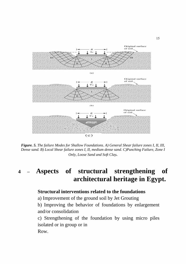
Figure. 5. The failure Modes for Shallow Foundations. A) General Shear failure zones I, II, III,
Dense sand. B) Local Shear failure zones I, II, medium dense sand. C)Punching Failure, Zone I
Only, Loose Sand and Soft Clay.
4 – Aspects of structural strengthening of
architectural heritage in Egypt.
Structural interventions related to the foundations
a) Improvement of the ground soil by Jet Grouting
b) Improving the behavior of foundations by enlargement
and/or consolidation
c) Strengthening of the foundation by using micro piles
isolated or in group or in
Row.

16
Local interventions for structural improvement
a) Masonry walls grouting and Injections in cracks
b) Strengthening roof diaphragms with plywood
c) Transversal anchorage in walls
d) Strengthening masonry column with jacketing
e) Repair of damaged wood elements
Global interventions for structural improvement
a) Strengthening of masonry walls with reinforced cement
coating (shotcrete or jacketing)
b) Strengthening of masonry walls with polypropylene
meshing
c) Strengthening of floors and improving the connection
floor/wall
d) Strengthening of masonry walls with composite materials
(CFRP and GFRP
e) The use of horizontal tie rods
f) Retrofitting by post tensioning
f) Strengthening with ring beams
g) Retrofitting by introducing RC shear walls
h) Strengthening with RC or steel frames or braced frames.
(Hemeda, 2014c)
5- Application of micropiles in preservation of
historical buildings.
Micropiles can be used for underpinning existing structures.
Micropiles can be installed through, and bonded within,

17
existing structures, providing direct connection with
competent underlying strata without the need for new pile
caps, at the same time it reinforces the structure internally.
Structural movements caused due to variety of factors, such
as compressible ground beneath the existing foundation,
dewatering activities groundwater elevation fluctuations,
deterioration of existing foundations, and adjacent deep
excavations and tunneling activities can be mitigated by use
of Micropiles. Thus providing improved structural support
and increased load-bearing capacity of an existing
foundation. Load transfer structure is often provided
between the micropiles and the existing superstructure.
The existing superstructure is structurally integrated with
new piles or jet columns and piles are installed by jacking.
Preloading is implemented by mounting a tendon inside the
micropile and jacks are used to straighten or lift the
superstructure, (Karpe et al, 2011., Nayak, 1990).
Micropiles are similar to conventional piles, but with
diameter less than 30cm which makes them convenient to
cast under any given situations.
MicroPiles are classified to two categories according to the
method of load transfer:
1- End Bearing Piles: Tip point carries most of the load.
Transmit most of their loads to the load bearing layer (dense
sand or rock). Most of the pile capacity inferred from the
end bearing point.

18
2- Friction Piles: Side friction carries most of the load.
Transmit most of their load through the layers through
which the piles pass, i.e., mostly through the surface friction
with the surrounding soils.
Figure. 6. Classification of Micro Piles according to its design.
Micro piles are designed to transfer load through shaft
friction over a length of pile shaft to founding medium.
1) They have been used effectively in many applications
of ground improvement to increase bearing capacity and
reduce settlements particularly in strengthening existing
foundation.
The frictional resistance between surface of pile & soil
and associated group/network effects of micropile are
considered as possible mechanism of improvement.

19
2) Micropiles have been widely used in applications
such as structural support for new foundations, underpinning
of existing foundations, earth retention, soil stabilization,
seismic retrofitting, etc.
This small diameter piles offer various advantages like ease
in construction in sites with constraints such as low head
room, adjacent existing structures and congested areas,
difficulty in transporting piling equipment and places where
it is required to eliminate noise and vibration problems.
Micropiles can also be installed in almost any ground
condition (Mascardi, 1982). Micropiles are considered to
provide solution in converting existing large open spaces
into usable floors without disturbing the façade of the
structure, thus retaining the heritage structures.
Also, applicability of these techniques for
renovation/rehabilitation of old historical monuments and
structures is also explored, (Kordahi, 2003).
5.1 Micro piles specifications
- Small / Diameter Injected Piles Low Pressure / High
Pressure
- Reinforced with Steel Pipe
- Diameter 20 - 30cm
- Depth Up to 30m
20
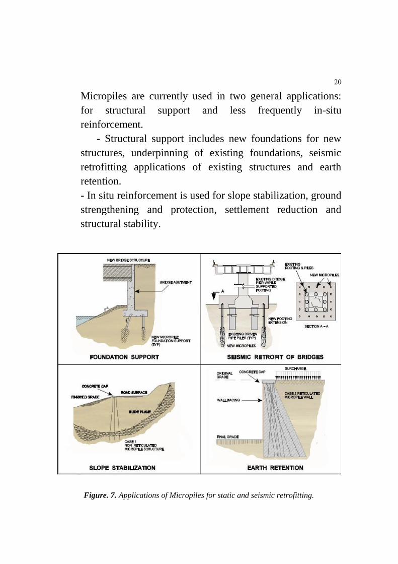
Micropiles are currently used in two general applications:
for structural support and less frequently in-situ
reinforcement.
- Structural support includes new foundations for new
structures, underpinning of existing foundations, seismic
retrofitting applications of existing structures and earth
retention.
- In situ reinforcement is used for slope stabilization, ground
strengthening and protection, settlement reduction and
structural stability.
Figure. 7. Applications of Micropiles for static and seismic retrofitting.

21
5.2 Installation of Micropiles
The construction of a micropile involves a succession of
processes, the most significant of which are drilling placing
the reinforcement, and grouting. The materials used in
construction of micropile include grout and reinforcement.
The main steel component and the grout shaft of the
micropile shall be designed to support the external loads and
bending to be transmitted to/from the load bearing stratum
for end-bearing/tension piles, which shall consist of a top
anchorage or pile cap and an axial
steel component, (FHWA, 2005).
Construction Technique
The typical construction sequence for micropiles includes
drilling the pile shaft to the required tip elevation, placing
the steel reinforcement, placing the initial grout by tremie,
and placing additional grout under pressure.
Drilling Method
The selected drilling methods are acceptable, provided they
can form a stable hole of the required dimensions and within
the stated tolerances, and without detriment to their
surroundings. Drilling within a congested urban site in close
proximity of older buildings or deteriorating foundations has
very different constraints than drilling for new foundations
on an open field site. The act of drilling and forming the pile
hole may disturb the surrounding ground for a certain time

22
and over a certain distance. The drilling method selected
should avoid causing an unacceptable level of disturbance to
the site and its facilities, while providing for installation of a
pile that supports the required capacities in the most cost-
effective manner, (Deshmukh and Ganpule, 1990).
Grouting
The grouting operations have a major impact on micropile
capacity. Grout transfers the imposed loads between the
reinforcement and the surrounding ground. and form part of
the load-bearing cross section of the pile .It also protects the
steel reinforcement from corrosion. The grout therefore,
needs to have adequate properties of fluidity strength,
stability, and durability. (Karpe et al, 2011).
5.3 Materials to be used
1. Grout
Grout shall be mixed from Ordinary Portland Cement and
clean water free from harmful substances. Usage of other
cement which has a higher strength and/or workability shall
also be allowed.
2. Grout Mix
The proportions of grout and the minimum strength of work
cubes shall comply with the following requirements:
Range of water/cement ratio
0.42-0.50(Typically 0.45)
Target Resistance to crushing (cube strength)
7 days 21 N/mm

23
28 days 30 N/mm
The quantities of cement in the mix shall be measured by
weight. The grout shall be free from segregation, slumping
and bleeding. Grout shall be mixed on site and shall be
pumped into its final position as soon as possible, (Bowels,
1979).
6 – Bearing Capacity pf piles from soil parameters
Static Formula Method (Qu = Qb + Qs)
Embedd
ed Length
= D
Qu = Ultimate Bearing Capacity
Qs = fAs
f = Unit Frictional Resistance
AS = Shaft Area (Pile surface area)
qb = Unit Bearing Capacity
of tip point Ab = Area of Pile Base
Qb = qbAb
24
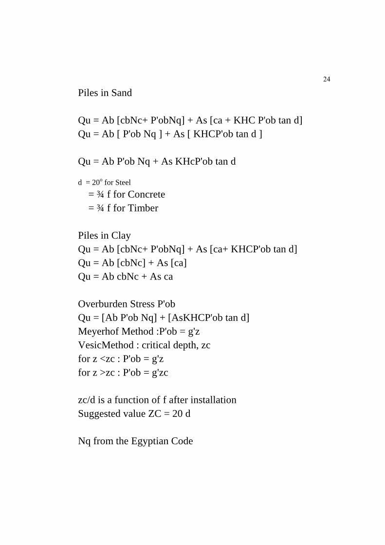
Piles in Sand
Qu = Ab [cbNc+ P'obNq] + As [ca + KHC P'ob tan d]
Qu = Ab [ P'ob Nq ] + As [ KHCP'ob tan d ]
Qu = Ab P'ob Nq + As KHcP'ob tan d
d = 20o for Steel
= ¾ f for Concrete
= ¾ f for Timber
Piles in Clay
Qu = Ab [cbNc+ P'obNq] + As [ca+ KHCP'ob tan d]
Qu = Ab [cbNc] + As [ca]
Qu = Ab cbNc + As ca
Overburden Stress P'ob
Qu = [Ab P'ob Nq] + [AsKHCP'ob tan d]
Meyerhof Method :P'ob = g'z
VesicMethod : critical depth, zc
for z <zc : P'ob = g'z
for z >zc : P'ob = g'zc
zc/d is a function of f after installation
Suggested value ZC = 20 d
Nq from the Egyptian Code

25
Table (1): Nq Values Vs f for Sand, Egyptian Code.
Nc for Clay
Nc = 9.0 for calculating the end bearing resistance of piles
in clay.
7 - The mosque of Al-ZaherBaybars in cairo,
Egypt. (Case study).
The Mosque of Sultan Al-ZahirBaybars is a square-shaped
building that is surrounded by a stone wall. The top of the
stone wall is decorated by a row of cresting.
Four towers fortify the exterior corners of the mosque. The
mosque has three monumental projecting entrances.
The main entrance is at the western wall. It leads to a
passage with a dome ceiling at the beginning and with a
shallow dome at the end.
In the interior of the mosque there is a quasi-square court
surrounded by aisles on all four sides. The most
distinguished feature of this mosque is the chamber that
precedes the mihrab, or niche indicating the direction of
40 35 30 25 oᵠ
φ
150 75 30 15 Nq

26
Mecca. It has a quasi-square structure, which occupies nine
tiles and is covered with a red brick dome.
The south aisle consists of six colonnades. The eastern and
the western aisles consist of three colonnades each. The
northern aisle contains two colonnades and all its arches are
supported by marble columns, (Doris and Abbouseif, 2007).
Figure. 8 .Main Façades and cross section of Al-ZahirBaybarsmosque in Cairo, Egypt.

27
Figure. 9. Al-ZahirBaybars mosque in Cairo, Egypt. Present state of deterioration and structural
damage.
7-1 Geotechnical Investigations in the site.
The geotechnical investigations inside the Mosque included
the subsurface exploration (test pits - less than 8 ft in depth;
borings and geotechnical boreholes- greater than 8 ft) -
Estimate level of water table GWT conditions
(piezometers)- Testing of soil sample in laboratory for
various properties: Particle size distribution, Liquid limit,
Plastic limit, Water content, Permeability, Shrinkage/
swelling, Shear/compressive strength, Consolidation (Creep
and settlement). The results from the Oedometer-
Consolidation test are presented in figures (10-14).
1 - Filling of Fill (silty clay and limestone fragments, calc,
dark brown) from ground surface 0.00m to 3.50m depth.

28
2 - Sand Fill (silty clay, medium, traces of limestone& red
brick fragments, calc, dark brown) from 3.50m to 5.00m
depth.
3 – Silty clay, stiff, calc, dark brown from 5.00m to 6.50m
depth.
4 – Clayey silt, traces of fine sand & mica, yellowish dark
brown from 6.50m to 8.50m depth.
5 – Silty sand, fine, traces of clay & mica. Dark brown.
From 8.50m to 11.00m depth.
6 – Sand, fine, some silt, traces of mica, yellowish dark
brown. From 11.00m to 14.00m depth.
7 – Sand, fine to medium, traces of silt& mica, traces of fine
to medium gravel, traces of marine shells, yellowish dark
brown. From 14.00m to 16.00m depth.
8 – Sand, fine, traces of silt & mica, yellowish dark brown.
From 16.00m to 18.00m depth.
9 – Sand & Gravel, medium sand, graded gravel, traces of
silt, yellow dark brown. From 18.00m to 20.00m depth. End
of drilling at 20.00m.
1
10
100
1000
10000
0 0.01 0.02 0.03 0.04 0.05 0.06 0.07
log
σv
(kp
a)
strain (ε)

29
Figure 10. Vertical stress vs vertical strain.
Figure. 11. Coefficient of consolidation vs vertical sress.
Figure 12. Modulus of Compression vs vertical stress.
0
0.00005
0.0001
0.00015
0.0002
0.00025
0.0003
1 10 100 1000 10000co
eff
icie
nt
of
co
nso
lid
ati
on
Cv
(m
2/s
ec)
log σv ( kpa)
Cv ( m2/sec)
0
5000
10000
15000
20000
25000
30000
35000
40000
45000
50000
1 10 100 1000 10000
mo
du
lus o
f co
mp
ressio
n (
E)
log σv ( kpa)
modulus of compression (E)

30
Figure 13. Vertical stress vs void ration and the determination of (Pc) and (Cc).
Figure 14. Oedometer test Procedure in the laboratory.
0
0.1
0.2
0.3
0.4
0.5
0.6
0.7
0.8
1 10 100 1000 10000
vo
id r
ati
o(e
)
log σv (kpa)
void Ratio (e)
loading
unloadingPc =480 kpaCc =0.23157

31
7-2 Static and Seismic response analysis
Properties of material used in analysis:
Material Brick: weight per unit volume = 2.00 t/m3, Young's
modulus= 1242000 t/m2 -
Material wood: weight per unit volume = 0.60 t/m3, Young's
modulus= 1100000 t/m2 -
Loads: Finishing load= 0.35 t/m2, Live load= 0.10 t/m
2
EQ response: Seismic zone 3, Classification of soil
conditions C, see tables (2) and (3)
The results from the static and dynamic numerical study are
presented in tables (4) and (5)
Table. 2. Frame section properties
Table. 3. Area section properties
32
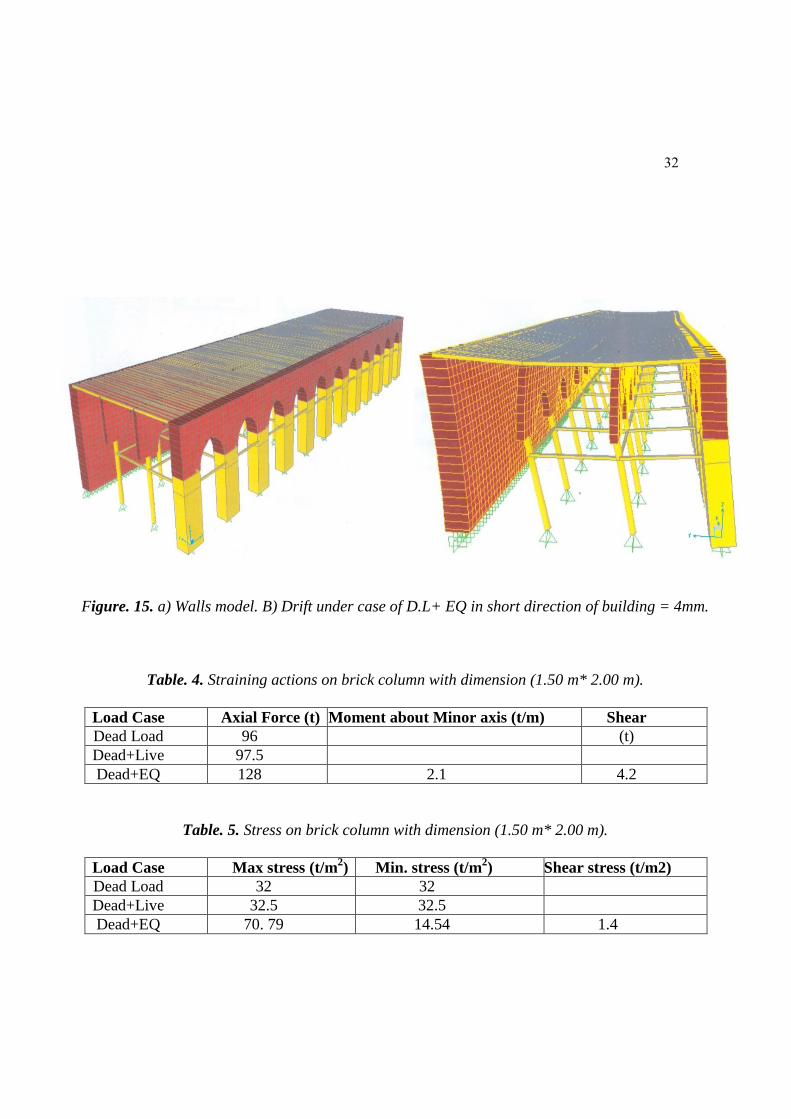
Figure. 15. a) Walls model. B) Drift under case of D.L+ EQ in short direction of building = 4mm.
Table. 4. Straining actions on brick column with dimension (1.50 m* 2.00 m).
Shear Moment about Minor axis (t/m) Axial Force (t) Load Case
(t) 96 Dead Load
97.5 Dead+Live
4.2 2.1 128 Dead+EQ
Table. 5. Stress on brick column with dimension (1.50 m* 2.00 m).
Shear stress (t/m2) Min. stress (t/m2) Max stress (t/m
2) Load Case
32 32 Dead Load
32.5 32.5 Dead+Live
1.4 14.54 70. 79 Dead+EQ

33
Figure. 16. Stresses on arches
7-3 Recommendations injection soil down the foundations of Mosque of Al-
ZahirBaybars in Cairo, Egypt.
Areas based on layers or backfill soil is weak and strengthen
the foundations according to the following:-
- Injection layers of backfill soil or weak surface down walls
and foundations using appropriate materials ( mortar cement
or resin ) , which is working to fill the void and gaps layers
of backfill as well as the cohesion of the components of the
soil together and extends the work of injection until the
onset of layers of clay soil sound taking into account the
extension of the injection of each side down the foundations

34
and walls for a distance in the range of half the depth of the
injection , and a minimum of 50 cm and that is after the end
of the injection taking soil samples that have been injected ,
and to conduct laboratory experiments needed to determine
the intensity and effort breakage her so that not less than 12
kg / cm 2
That are expected to account landing layers of clay soil
injection works to backfill layers -
This was followed by the restoration work of the
foundations of the original (or bar rules) injection of the
work of the foundations of heavy grouting and replacement
of damaged parts and repair other parts
7-4 Recommendations of Micro piles down the foundations of Mosque of Al-
ZahirBaybars in Cairo, Egypt.
Piles can be implemented needle-class implementation of the following:
1) Piles needle diameter is 20 to 30 cm and 20 ton payload design
2) Arming of steel pipe piles 52 diameter 9.88 mm and
thickness of 10 mm full length of the pile, that is connected
parts thereof in accordance with the instructions of the
Egyptian Code of Facilities mineral allowing to connect
structural continuous arming (Continuity to Flexural
Rigidity)
3) Is performed Piles needle system of low pressure (Low
Pressure Grouting?)
4) Cement mortar used in the molding pile but at least have
a stress fracture about 200 kg / cm 2 after 28 days.

35
5) are taking precautions to ensure the Executive Active
vertical hole pile and smoothing mortar Balkhazouk sector ,
as well as the regularity of the thickness of the cover of
mortar ( 10 cm at least) about the pipe reinforcement .
6) Is reviewing the structural contact between the pipes and
rebar important Piles allowing explicit move loads on a
regular basis to secure the piles needles with safety factor
intrusion (Punching).
7) The pile length 16 meters, at least as measured by the
level of the surface of the Earth's natural places borings at
the time of implementation.
8) Recommended action characterization of the output of
drilling and preparation of the soil for each sector hazing
and recording the amount of mortar used in the casting of
the pile with the possibility of depth compared with the
theoretical size of the stake to confirm the actual
complementary pile.
9) The implementation of complementary experiments
hazing ((Pile Integrity Tests on all piles.
10) we recommend that you download experience on hazing
is worker before starting to implement Piles working so
twice the value of operating for the stake, according to the
instructions contained Part IV CODE Egyptian Foundations
(deepfoundations) and your load Static of the piles with the
implementation experiences of load on the pile working at a
rate experience for each 200 hazing factor.

36
Figure.17.Side of the geotechnical investigations (foundation pits) at Al-ZahirBaybarsmosque in
Cairo, Egypt.
Figure. 18 . Design of MicroPiles application in Mosque of Al-ZahirBaybars in Cairo, Egypt.
37
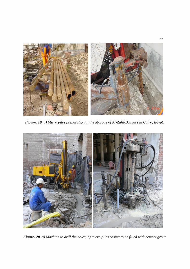
Figure. 19 .a) Micro piles preparation at the Mosque of Al-ZahirBaybars in Cairo, Egypt.
Figure. 20 .a) Machine to drill the holes, b) micro piles casing to be filled with cement grout.

38
Figure. 21. Multiple leaf masonry walls after restoration and foundation reinforcement.
Figure. 22 . Soil replacement and improvement at Mosque of Al-ZahirBaybars in Cairo, Egypt.
39
8- Micrpiles limitations
High slenderness ratio (length/diameter) of micropiles limits
its applications in structures which require higher factor of
safety. Micropiles are not acceptable for conventional
seismic retrofitting applications in areas where liquefaction
may occur.
Use of micropiles for slope stabilization has been applied to
limited heights In driven piles, usually the cost of micropiles
exceeds conventional piling system Howeverunder certain
combinations of circumstances, micropiles will be the cost-
effective option, and occasionally will be the only feasible
constructible options.
9. Concluding remarks
Even if the research and the evaluation of its results are still
ongoing, some concluding remarks can be drawn from the
direct experience collected and monitored in the Database.
- Micro Piles are used in: 1- Upper soil is weak,
compressible, or could not support the surface loads. 2- The
loads are tension, horizontal, or inclined. 3- Problematic
soils; -Swelling soils giving tension on the pile -Collapsing
sandy soils, adding down-drag forces on the pile.
- Advantages of Micro piles in restoration of monuments:
High capacity, relatively inexpensive, usually durable and
corrosion resistant in many environments (not marine).
40
Disadvantages of Micro piles in restoration of monuments:
Handling, splicing, and transportation difficulties (for
precast piles). Soil caving in cast in-situ piles.
- When using new techniques and materials experimental
research has to be carried out before, not only on the
mechanical behaviour but also on the physical and chemical
compatibility with the existing structure and materials.
As regards compatibility problems, it is worth noting that
repair techniques were used in the past centuries and the
present ones are sometimes only a proposal of them using
modern materials, which can be incompatible with the
existing ones. A better knowledge of the traditional
techniques and new research to apply them in a modern way
will be one of the major issues of the future research of the
author in this field. At present, in fact, very few research has
been carried out on the behaviour of stone structures before
choosing the appropriate repair techniques.
41
10. References
Bowels. J.E, "Physical and Geotechnical Properties of Soil"
(McGraw- Hill Book Company 1979).
Doris Behrens-Abbouseif, "Cairo of the Mamluks: A
History of the Architecture and its Culture," London: I.B.
Tauris and Co. Ltd., 2007, 3.
Herbst, Thomas (2007-09-27). "Historical Review and
Analysis of 55 Years of Micropiles".IWM 2007, Toronto,
Canada.
"International Society for Micropiles". Archived from the
original on 2007-07-08. Retrieved 2007-02-15
Deshmukh, A.M. &Ganpule, V.T. “Design and
construction of mini grouted piles in Bombay region.” Pile
talks International Jakarta, Indonesia, July 1990.
FHWA, Manual“Micropile Design and Construction
Reference Manual”, FHWA, 2005.
Kordahi, R. “Underpinning strategies for Buildings with
Deep Foundation” M.E. dissertation, American University
of Beirut, 2003.

42
Nayak, N. V. “Foundation Design Manual” for practicing
Engineers and civil engineering students, Dhanpat Rai &
sons, 1990
Karpe.V.M.,Dias.N., Sarang..P.Y" Micropiles –An
Innovative Ground Improvement Tool" International Journal
of Earth Sciences and Engineering 11, Volume 04, No 06
SPL, October 2011, pp 11-14
Sayed Hemeda.,Kyriazis PITILAKIS “The Serapeum
temple and the ancient annex library in Alexandria, Egypt:
Geotechnical-geophysical investigations and stability
analysis under static and seismic conditions”. International
Journal of Engineering Geology. Vol 113, issues 1-4. May
2010.
Sayed Hemeda "Ground Penetrating Radar (GPR) in
Preservation of Architectural Heritage in Egypt. Case study
of Habib Sakakini palace. Open journal of geology. Volume
2, Issue 3, July 2012a.
Sayed Hemeda "Ground Penetrating Radar (GPR) in
Preservation of Architectural Heritage in Egypt. Case study
of Habib Sakakini palace. International journal of
Conservation science. Volume 3, Issue 3, September 2012b.
Sayed Hemeda "Grouting of multiple leaf-masonry walls:
application on some Islamic historical monuments, Cairo,
Egypt" International journal of Conservation science.
Volume 3, Issue 4, December 2012c.
43
Sayed Hemeda, Kyriazis PITILAKIS, Stavros BANDIS
"Geotechnical, Geophysical Investigations and Seismic
Response Analysis of the Underground Tombs in Mustafa
Kamil Necropolis, Alexandria, Egypt." Mediterranean
archaeology and archaeometry. Vol. 14.2, 2014a.
Sayed Hemeda "Seismic Hazard Analysis for Architecture
Heritage Preservation in Egypt: The Case of the Cairo's
Oldest, Abu Serga Church". Journal of Civil Engineering
and Science (JCES). Vol 3.1
2014b.
Sayed Hemeda, El-Sayed El-Banna, "Structural deficiency
and intervention measures on rubble filled walls in Islamic
historical buildings in Cairo, Egypt" Mediterranean
archaeology and archaeometry.Vol 1, 2014c.

44
Author contact
Sayed Hemeda
-Assistant Professor, Conservation Department, Faculty of
Archaeology, Cairo University, Egypt.
-Associate Professor, Civil Engineering, Faculty of Engineering,
UBT, Saudi Arabia.
e-mail: [email protected]., [email protected].
ISBN: 978-88-98161-32-4
: