oval wheel meter small oi range - bopp & reuther docu...
TRANSCRIPT

Bopp & Reuther Messtechnik GmbH Am Neuen Rheinhafen 4 67346 Speyer Deutschland
Telefon: +49 (6232) 657-0 Fax: +49 (6232) 657-505 [email protected] www.bopp-reuther.de
A-EN-01211-KLRev.E 12/2013
Seite 1 von 19
Oval Wheel Meter Small OI Range with Pulse Pick-Ups AG 19/20/41 with Mechanical Counters R7
Operating Manual

Small OI Oval Wheel Meters with Mechanical Roller Counter and/or Pulse Pick-Up Operating manual
Page 2 of 19 Errors and alterations excepted.
A-EN-01211-KLRev.E Bopp & Reuther Messtechnik GmbH
Contents
FOREWORD __________________________________________________________________________ 4
I. TRANSPORT, DELIVERY, STORAGE ________________________________________________________ 4 II. WARRANTY ________________________________________________________________________ 4
1. IDENTIFICATION ____________________________________________________________________ 4
2. AREA OF APPLICATION ______________________________________________________________ 4
3. PRINCIPLE OF OPERATION AND SYSTEM DESIGN _______________________________________ 5
3.1 MEASURING PRINCIPLE _______________________________________________________________ 5 3.2 SYSTEM DESIGN ____________________________________________________________________ 5
4. INPUT _____________________________________________________________________________ 6
4.1 MEASURED VARIABLE ________________________________________________________________ 6 4.2 MEASURING RANGE _________________________________________________________________ 6
5. OUTPUT ___________________________________________________________________________ 7
5.1 OUTPUT SIGNAL ____________________________________________________________________ 7 5.1.1 Pulse pick-up AG 19, AG 20 and AG 41 _____________________________________________ 7 5.1.3 Mechanical roller counter R7 _____________________________________________________ 8
5.2 ELECTRICAL AND THERMAL SAFETY RELEVANT DATA __________________________________________ 8
6. CHARACTERISTIC VALUES ___________________________________________________________ 8
6.1 REFERENCE CONDITIONS _____________________________________________________________ 8 6.2 MEASURED ERROR __________________________________________________________________ 8 6.3 REPEATABILITY ____________________________________________________________________ 8 6.4 AMBIENT TEMPERATURE INFLUENCE _____________________________________________________ 9 6.5 LIQUID TEMPERATURE INFLUENCE _______________________________________________________ 9
7. OPERATING CONDITIONS ____________________________________________________________ 9
7.1 INSTALLATION CONDITIONS ____________________________________________________________ 9 7.1.1 Installation notes _______________________________________________________________ 9
7.1.1.1 General notes ______________________________________________________________ 9 7.1.1.2 Installation ________________________________________________________________ 9
7.1.2 Start-up conditions ____________________________________________________________ 10 7.1.3 Changing the direction of flow ____________________________________________________ 10
7.2 AMBIENT CONDITIONS _______________________________________________________________ 10 7.2.1 Ambient temperature ___________________________________________________________ 10 7.2.2 Storage temperature ___________________________________________________________ 10 7.2.3 Degree of protection ___________________________________________________________ 10 7.2.4 Electromagnetic compatibility ____________________________________________________ 11
7.3 PROCESS CONDITIONS ______________________________________________________________ 11 7.3.1 Liquid temperature ____________________________________________________________ 11 7.3.2 State of aggregation ___________________________________________________________ 11 7.3.3 Viscosity ____________________________________________________________________ 11 7.3.4 Liquid temperature limit _________________________________________________________ 11 7.3.5 Liquid pressure limit ___________________________________________________________ 11 7.3.6 Flow rate limit ________________________________________________________________ 11 7.3.7 Pressure loss ________________________________________________________________ 12
8. CONSTRUCTIVE DESIGN ____________________________________________________________ 13
8.1 MODEL/DIMENSIONS _______________________________________________________________ 13 8.2 WEIGHT _________________________________________________________________________ 14 8.3 MATERIAL _______________________________________________________________________ 14 8.4 PROCESS CONNECTION _____________________________________________________________ 14 8.5 ELECTRICAL CONNECTION ____________________________________________________________ 15
9. DISPLAY __________________________________________________________________________ 16
Operating manual Small OI Oval Wheel Meters with Mechanical Roller Counter and/or Pulse Pick-Up
Bopp & Reuther Messtechnik GmbH
A-DE-01211-KLRev.E
Errors and alterations excepted.
Page 3 of 19
9.1 GENERAL ________________________________________________________________________ 16
10. CERTIFICATES AND APPROVALS ____________________________________________________ 16
APPENDIX __________________________________________________________________________ 17
A. TROUBLESHOOTING _______________________________________________________________ 17
B MAINTENANCE, CLEANING, CHANGING THE INDICATORS ________________________________ 17
B.1 MAINTENANCE, CLEANING ___________________________________________________________ 17 B.2 REPAIRS, HAZARDOUS SUBSTANCES ___________________________________________________ 17
C. FORMS ___________________________________________________________________________ 18
C.1 CERTIFICATE OF NON-OBJECTION FOR THE CONTRACTOR ____________________________________ 18
D. CERTIFICATES ____________________________________________________________________ 19
D.1. EC TYPE EXAMINATION CERTIFICATE DIRECTIVE 94/9/EC ___________________________________ 19 D.1.1 DMT 00ATEX E 063 X - PV11 (Nov. 2000) _________________________________________ 19 D.1.2 PTB 99 ATEX 2219 X - Slotted proximity switch SJ...(AG 19/20) (Dec. 1999) _______________ 19 D.1.2.1 1. Supplement - Slotted proximity switch SJ...(AG 19/20) (Oct. 2003) __________________ 19 D.1.2.2 2. Supplement - Slotted proximity switch SJ...(AG 19/20) (Nov. 2011) _________________ 19
D.2. EC-CONFORMITY DECLARATION (SEPT.2013) ____________________________________________ 19

Small OI Oval Wheel Meters with Mechanical Roller Counter and/or Pulse Pick-Up Operating manual
Page 4 of 19 Errors and alterations excepted.
A-EN-01211-KLRev.E Bopp & Reuther Messtechnik GmbH
Foreword
I. Transport, Delivery, Storage
Storage and transport:
Protect devices against humidity, soiling, impacts and damages
Inspection of the delivery:
Upon receipt, check the delivery for completeness. Compare the device data with thedata on the delivery note and in the order records.
Report any in-transit damage immediately upon delivery. Damages reported at a later date shall not be recognised.
II. Warranty Please refer to the contractual terms and conditions relating to delivery for the scope and period of warranty. Warranty claims shall be conditional to correct installation and commissioning in accordance with the operating instructions of the device. The necessary installation, start-up and maintenance work should only be carried out by qualified and authorized personnel.
1. Identification
Manufacturer Bopp & Reuther Messtechnik GmbH Am Neuen Rheinhafen 4 67346 Speyer, Germany Phone : +49 (0)6232 657-0 Fax : +49 (6232) 657-505
Type of product Direct volumetric meter (positive displacement meter) Product name OI oval wheel meters with pulse pick-ups AG 19/20 or/and mechanical R7 counters Version no. A-DE-01211-KLRev.E
2. Area of Application
The quantity control of certain industrial liquids is an economic necessity considering the high value of these products. The design and materials of the volume measuring instruments required for these procedures have to be adapted to the particular operating conditions and characteristics of the liquids to be measured. The field of application for OI oval wheel meters includes measuring, metering and controlling of liquids. OI oval wheel meters meet all these requirements. They are used for measuring liquid semi-finished and finished products, such as liquid gases, acids, alkalis, greases, alcohols, solvents, dispersions, polymerisates, polycondensates, varnishes, paints, adhesives, etc. The measurement of liquids with very high viscosity and a low pressure loss should be particularly emphasized in this respect. Small OI oval wheel meters are produced with a nominal width of 6 to 15 mm. Depending on the nominal width and the type of material, they can be used up to PN 40; the maximum permissible operating temperature is 170°C.

Operating manual Small OI Oval Wheel Meters with Mechanical Roller Counter and/or Pulse Pick-Up
Bopp & Reuther Messtechnik GmbH
A-DE-01211-KLRev.E
Errors and alterations excepted.
Page 5 of 19
3. Principle of Operation and System Design
3.1 Measuring principle Oval wheel meters are direct volumetric meters for liquids with movable partitions (displacement flow meters). The oval wheel meter consists of a measurement chamber housing with two pivoted oval wheels which are toothed and roll off each other in counter-rotations.
The diagram displays oval wheel movement during the measurement process.
Each rotation of the oval wheels displaces four discrete volumes of liquid through the meter (between the oval wheel and measurement chamber).
The rotation of the oval wheel meter is transferred to a mechanical counter and/or a pulse pick-up via a magnetic clutch and gearing for measurement purposes.
3.2 System design Oval wheel meters with attachments comprise the following components: Sensor: Measured value logging occurs via OI series oval wheel meters. Pulse pick-up AG 19 and AG 20: The AG 19 and/or AG 20 pulse pick-up is used for controlling electro-mechanical counters (observe fmax.), indicators, recorders, regulators, electronic meters, data processing systems as well as remote readout printers with a step motor. Pulse pick-up AG 41: The AG 41 pulse pick-up is used for controlling electronic meters, indicators, recorders, regulators, data processing systems as well as remote readout printers with a step motor. Roller counter R7
OI small oval meters are available with a 7-digit non-resettable counter. The counter can be combined with the AG 19 and AG 20 pulse pick-ups.

Small OI Oval Wheel Meters with Mechanical Roller Counter and/or Pulse Pick-Up Operating manual
Page 6 of 19 Errors and alterations excepted.
A-EN-01211-KLRev.E Bopp & Reuther Messtechnik GmbH
4. Input
4.1 Measured variable Liquid volumes and volumetric flow rate 4.2 Measuring range
Measuring ranges for media with Newtonian flow properties
Type DN Flow rate
Qmax [ℓ/h]
Load at viscosity
0.3 – 0.8 mPa•s
0.8 – 2 mPa•s
2 - 50 mPa•s
50 - 150 mPa•s
150 – 350 mPa•s
350 - 1000 mPa•s
[ℓ/min] [ℓ/h] [ℓ/min] [ℓ/h] [ℓ/min] [ℓ/h]
[ℓ/min] [ℓ/h] [ℓ/min] [ℓ/h] [ℓ/min] [ℓ/h]
OI 03
6 15
120
Min 0.3 20 0.2 12 0.2 12 0.18 11 0.1 6 0.03 2 Max 1.6 100 2 120 2 120
1.8 110 1 60 0.4 25 Continuous processing 1 60 1.3 80 1.8 110
Batch processing 1.3 80 1.8 110 2.0 120
OI 06
10 15
250
Min 0.6 40 0.4 25 0.4 25 0.3 20 0.2 13 0.08 5 Max 3.3 200 4.1 250 4.1 250
3.7 225 2.1 130 0.8 50 Continuous processing 2.1 130 2.6 160 1.8 110
Batch processing 2.6 160 3.7 225 4.1 250
OI 1 15 600
Min 1.6 100 1 60 1 60 0.9 54 0.6 36 0.2 12 Max 8.3 500 10 600 10 600
9 540 6 360 2 120 Continuous processing 5 300 6.6 400 9 540
Batch processing 7.5 450 9 540 10 250
The values in the table are general nominal ratings. The exact range depends on the measured media, viscosity and type of meter and is listed in the data sheet. Measuring ranges for cold water: Use the values in column 0.3 – 0.8 mPa•s; 50% and 70% of the maximum flow rate must be used for permanent load and maximum load or batch processing respectively.
Measuring ranges for sulphuric acid
Type DN Flow rate Qmax [ℓ/h]
Load at temperature
up to 20°
up to 30°
up to 40°
[ℓ/min] [ℓ/h] [ℓ/min] [ℓ/h] [ℓ/min] [ℓ/h]
OI 03
6 15
120
Min 0.2 12 0.2 12 0.2 12 Max 2 120 1.6 96 1.3 78
Continuous processing 1.3 78 1 60 0.8 48
OI 06
10 15
250
Min 0.34 20.4 0.34 20,4
0.34 20,4
Max 4.2 252 3.4 204 2.7 162Continuous processing 2.7 162 2.2 132 1.7 102
OI 1 15 600
Min 1 60 1 60 1 60 Max 7 420 5.6 336 4.6 276
Continuous processing 4.6 276 3.7 222 2.8 168

Operating manual Small OI Oval Wheel Meters with Mechanical Roller Counter and/or Pulse Pick-Up
Bopp & Reuther Messtechnik GmbH
A-DE-01211-KLRev.E
Errors and alterations excepted.
Page 7 of 19
5. Output
5.1 Output Signal 5.1.1 Pulse pick-up AG 19, AG 20 and AG 41
AG 19 and AG 20
Technical data
Number of control flags 1/2/10/20/32
Max. permissible speed 350/min
Max. pulse frequency 187 Hz, depending on the meter version
Permissible ambient temperature
-25 to +90°C
Degree of protection for housing IP 54 (DIN 40 050)
Degree of protection for control head
IP 67 (DIN 40 050)
Ex-protection PTB 99 ATEX 2219 x II 2G EEx ia IIC T6
Connection of external devices In compliance with EN 50227 (NAMUR) and ex-approval
Oval wheel meter Data
Pulse pick-up frequency in regard to Qmax
10 Hz for: Remote readout
> 10 Hz for: Control, display, registering, etc.
Type
DN
Qm
ax
nA
G
Dis
pla
y
Co
un
ter
Slot number of the flag disc
1 2 10 10 20 32
Mm
ℓ
min
U
min
ℓ or m³
Pulse ℓ
Pulse
s
Pulse
ℓ
Pulse
s
Pulse
ℓ
Pulse
s
Pulse
ℓ
OI 03 6 15
2 19.7 1 - - 100 - - - - - -
OI 06 10 15
4.2 42 1 10 20 100 - - 14 200 22.22 320
OI 1 15 10 100 1 10 20 - 16.7 100 33.3 200 53.3 320
AG 41 with pre-amplifier PV11
Technical data
Number of control wires 20 Max. permissible speed 1000/minMax. pulse frequency Max. 333.33 Hz, depending on the meter version Permissible ambient temperature
-40 to +70°C
Ingress protection for housing IP 65 (EN 60529) Ex-protection DMT 00 ATEX E 063 x II 2G EEx ib IIC T6/5/4 Connection of external devices In compliance with EN 50227 (NAMUR) and ex-
approval

Small OI Oval Wheel Meters with Mechanical Roller Counter and/or Pulse Pick-Up Operating manual
Page 8 of 19 Errors and alterations excepted.
A-EN-01211-KLRev.E Bopp & Reuther Messtechnik GmbH
The Wiegand pre-amplifier PV 11, in connection with the AG 41 pulse pick-up, is intended for volume pulse scanning with oval wheel meters. As a category 2G device it can be operated in Zone 1 potentially explosive atmospheres. The Wiegand sensor coils of the above mentioned pulse pick-up types are classed as “simple electrical apparatus” according to EN 60079-14:1997, Sections 3.21 and 12.2.1. Therefore, the explosion protection approval for the installed Wiegand pre-amplifier PV 11 applies to the overall device of the meter equipped with one of these pulse pick-ups. The spike pulses generated in the scanning unit by the Wiegand effect are translated into pulses with a width of 500µs by the downstream multi-vibrator at the trigger level. These are split into two separate NAMUR switching steps whose signals have a phase shift of 180°.
Type
DN Qmax nAg fmax Km
mm ℓ h
U
min
Pulse/s
approx.
Pulse/ℓ
approx.
OI 03 6 120 666.66 222.2 6666.66
OI 06 10 250 701.5 233.83 3367.2
OI 1 15 600 1000 333.33 2000
Exact values for the specifications pulse/ℓ or pulse/s are only available after the accuracy test. 5.1.3 Mechanical roller counter R7
OI small oval meters are available with a 7-digit non-resettable counter.
Roller counter max. reading 999,999.9 l
A single revolution of the last number roller equals 1 l
The smallest division of the last roller is 0.05 l
5.2 Electrical and thermal safety relevant data See Appendix EC Type Examination Certificates
6. Characteristic Values
6.1 Reference conditions Oval wheel meters are calibrated at test benches monitored by the German Board of Weights and Measures. Pressure: 2 to 7 bar. Temp: 20 to 30°C 6.2 Measured error Type Up to 0.8 mPa•s
10-100% of Qnom Up to 2 mPa•s 10-100% of Qnom
Up to 50 mPa•s 10-100% of Qnom
Up to 50 mPa•s 10-100% of Qnom
OI 03 < ± 2% < ± 1% < ± 0,4% < ± 0,3% OI 06 < ± 1% < ± 0,5% < ± 0,4% < ± 0,3% OI 1 < ± 1% < ± 0,5% < ± 0,4% < ± 0,3% 6.3 Repeatability < 0,1%
Operating manual Small OI Oval Wheel Meters with Mechanical Roller Counter and/or Pulse Pick-Up
Bopp & Reuther Messtechnik GmbH
A-DE-01211-KLRev.E
Errors and alterations excepted.
Page 9 of 19
6.4 Ambient temperature influence < 0.005% / °C 6.5 Liquid temperature influence Depends on the viscosity of the measured liquid.
7. Operating Conditions
7.1 Installation conditions 7.1.1 Installation notes
Warning Please read the operating instructions carefully prior to installation and start-up. Depressurize and allow the system to cool down prior to installation or disassembly.
7.1.1.1 General notes Bopp & Reuther oval wheel meters are precision flow meters. Input and output ports are closed to
prevent impurities entering the device. Only remove protective caps immediately prior to use. Observe operating data marked on the oval wheel meter. Also observe data in the order confirmation
and on the data sheet. If the device is to be used under different operating conditions, consult Bopp & Reuther Messtechnik GmbH in advance, always state the device number.
Install the oval wheel meter in the pressure pipe behind the pump. (approx. 3 m liquid column pressure drop for nominal flow rate).
Install the oval wheel meter in a way that it remains completely filled with liquid even when idle. In order to prevent measuring errors due to soiling etc., the user should take appropriate preventative
measures (e.g. strainer type N). Oval wheel meters which are to be used for liquid foodstuffs and stimulants should be thoroughly
cleaned prior to use (see Maintenance and Cleaning).
7.1.1.2 Installation Remove any impurities from the pipework. For this task, install a fitting part instead of the oval wheel
meter and flush the pipe. Only remove the protective caps at the oval wheel meter input and output ports immediately prior to
installation. Prevent any impurities entering the device during installation. The arrows on the oval wheel meter housing indicate the direction of flow. The housing cover of the oval wheel meter has to be vertical to ensure that the oval wheel axles are
positioned horizontally, irrespective of the pipework. Install the oval wheel meter strain-free into the pipework. The sensor can be used together with the pulse pick-up AG 19/20 and AG 41 according to the type of protection “intrinsically safe” in potentially explosive areas. AG 41 with pre-amplifier PV11: DMT 00 ATEX E 063 x II 2G EEx ib IIC T6/5/4 AG 19, AG 20: PTB 99 ATEX 2219 x II 2G EEx ia IIC T6
The EMC protection can only be guaranteed with shielded wires. The shielding has to be applied in the metal PG connecting bolts.

Small OI Oval Wheel Meters with Mechanical Roller Counter and/or Pulse Pick-Up Operating manual
Page 10 of 19 Errors and alterations excepted.
A-EN-01211-KLRev.E Bopp & Reuther Messtechnik GmbH
7.1.2 Start-up conditions
Important
Start up the oval wheel meter with a gradually increasing the flow rate.
In measuring systems for viscous liquids which require heating, switch on the heating system of the oval wheel meter, filter and pipework in sufficient time prior to start-up, subsequently start up the device with a gradually increasing flow rate.
7.1.3 Changing the direction of flow
If the meter head readout position needs to be altered during meter installation, please observe the following instructions:
Initially install the meter in the pipework making sure that the arrow on the housing points in the intended flow direction.
With oval wheel meters, ensure that the bearing shafts of the oval wheels are horizontal. This is the
case when the housing cover is vertical.
Depending on the installation position of the meter, the meter head might be positioned with the digital display is upside down or rotated by 90°.
When changing the flow direction, loosen the countersunk screws and adjust the mechanical display R7 to the required readout position before retightening the screws.
7.2 Ambient conditions 7.2.1 Ambient temperature
OI with AG 19 or/and AG 20: 0 to +90°C OI with AG 41: 0 to +60°C OI with roller counter R7: 0 to +90°C 7.2.2 Storage temperature
-25°C to +100°C 7.2.3 Degree of protection
OI with AG 19 or/and AG 20: IP54 OI with AG 41: IP65 OI with roller counter R7: IP54 In accordance with IP20 IEC 529/EN 60529
Mechanical display R7
Countersunk screws (2 on each side)
Bottom part of the meter

Operating manual Small OI Oval Wheel Meters with Mechanical Roller Counter and/or Pulse Pick-Up
Bopp & Reuther Messtechnik GmbH
A-DE-01211-KLRev.E
Errors and alterations excepted.
Page 11 of 19
7.2.4 Electromagnetic compatibility
Only applies for devices with pulse pick-ups: According to the EMC Directive 2004/108/EG, EN 61000-6-2, EN 61000-6-3 The "electromagnetic compatibility" is only guaranteed when the electronics housing is closed. If the electronics housing is open, interferences can arise due to EMC signal pick-up. 7.3 Process conditions 7.3.1 Liquid temperature
Basic type Pulse pick-up Roller counter R7
Ex- tension
Liquid temperature in °C max. AG19
AG20 AG41
OI03
60
90
90
170
170
OI06 OI1
90
60
170*
170*
170*
90
170*
*with special tolerances for higher temperatures 7.3.2 State of aggregation
Suitable for liquids 7.3.3 Viscosity
0.3 - 1000 mPa•s 7.3.4 Liquid temperature limit
170°C 7.3.5 Liquid pressure limit
Depends on the material (for materials see 8.3.) DN 6 DN 10 DN 15 F4 PN 25 PN 25 PN 25 F5 PN 40 PN 40 PN 40 7.3.6 Flow rate limit
All details in l/min OI 03 OI 06 OI 1 2 4.2 10

Small OI Oval Wheel Meters with Mechanical Roller Counter and/or Pulse Pick-Up Operating manual
Page 12 of 19 Errors and alterations excepted.
A-EN-01211-KLRev.E Bopp & Reuther Messtechnik GmbH
7.3.7 Pressure loss
OI 06
Dru
ckve
rlu
st in
[b
ar]
1,0
0,75
0,5
0,25
0
30*15*1*
15
0*
35
0*
10
00
*
0 50 100 150 200 250
Durchfluss *Viskosität in [mPas]
Q [ /h]ℓ
50*
80*
OI 1
Dru
ckv
erl
ust
in [
ba
r]
1,0
0,75
0,5
0,25
0
150*
80*
15*1*
35
0*
10
00
*
0 120 240 360 480 600
Durchfluss *Viskosität in [mPas]
Q [ /h]ℓ
50*
30*
OI 03
Dru
ckve
rlu
st
in [
ba
r]
1,0
0,75
0,5
0,25
0
50*
30*
15*
1*
80*
15
0*
35
0*
10
00
*
0 24 48 72 96 120
Durchfluss Q [ /h]*Viskosität in [mPas]
ℓ
2,0
1,75
1,5
1,25
Pre
ssur
e lo
ss [b
ar]
Flow Q [ℓ/h] *Viscosity [mPa·s]
Pre
ssur
e lo
ss [b
ar]
Pre
ssur
e lo
ss [b
ar]
Flow Q [ℓ/h] *Viscosity [mPa·s]
Flow Q [ℓ/h] *Viscosity [mPa·s]
Operating manual Small OI Oval Wheel Meters with Mechanical Roller Counter and/or Pulse Pick-Up
Bopp & Reuther Messtechnik GmbH
A-DE-01211-KLRev.E
Errors and alterations excepted.
Page 13 of 19
8. Constructive Design
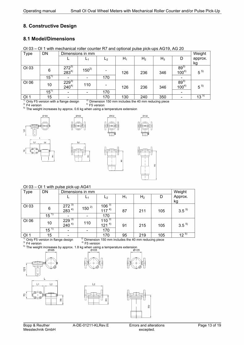
8.1 Model/Dimensions OI 03 – OI 1 with mechanical roller counter R7 and optional pulse pick-ups AG19, AG 20 Type DN Dimensions in mm Weight
approx. kg
L L1 L2 H1 H2 H3 D
OI 03 6
2723) 2834)
1502) - 126 236 346
893) 1004) 5 5)
151) - - 170 - OI 06
10 2293) 2404)
110 - 126 236 346
893) 1004) 5 5)
151) - - 170 - OI 1 15 - 170 130 240 350 - 13 5) 1) Only F5 version with a flange design 2) Dimension 150 mm includes the 40 mm reducing piece 3) F4 version 4) F5 version 5) The weight increases by approx. 0.6 kg when using a temperature extension
OI 03 – OI 1 with pulse pick-up AG41 Type DN Dimensions in mm Weight
Approx. kg
L L1 L2 H1 H2 D
OI 03 6
272 3) 283 4)
150 2) 106 3) 117 4) 87 211 105 3.5 5)
15 1) - - 170 OI 06
10 229 3) 240 4)
110 110 3) 121 4) 91 215 105 3.5 5)
15 1) - - 170 OI 1 15 - 170 95 219 105 12 5) 1) Only F5 version in flange design 2) Dimension 150 mm includes the 40 mm reducing piece 3) F4 version 4) F5 version 5) The weight increases by approx. 1.8 kg when using a temperature extension

Small OI Oval Wheel Meters with Mechanical Roller Counter and/or Pulse Pick-Up Operating manual
Page 14 of 19 Errors and alterations excepted.
A-EN-01211-KLRev.E Bopp & Reuther Messtechnik GmbH
8.2 Weight See 8.1 8.3 Material F4 F5 Housing brass CrNiMo Oval wheels
CrNiMo CrNiMo
Bearing Hardened carbon
Hardened carbon
8.4 Process connection Type Oval wheel meter and filter
DN Material Screwed pipe connection according to DIN 2353 pipe
Flange according to DIN
Flange according to ANSI
8x1 12x1 PN 25 PN 40 150 300 OI 03 6 F4
F5 1)
1) 1)
OI 06 10 F4 F5
1) 1)
1) OI 1 15 F4
F5 1)DN 15

Operating manual Small OI Oval Wheel Meters with Mechanical Roller Counter and/or Pulse Pick-Up
Bopp & Reuther Messtechnik GmbH
A-DE-01211-KLRev.E
Errors and alterations excepted.
Page 15 of 19
8.5 Electrical connection The electrical connections are located inside the terminal box.
AG 19 and AG 20
Connection of external devices In compliance with EN 50227 (NAMUR) and ex-approval
Control line max. up to 50 Ohm/wire
AG 19: 2-wires, shielded
AG 20: 4-wires, twisted in pairs
Cable connection M 20x1.5
AG 41 with pre-amplifier PV11
Connection of external devices In compliance with EN 50227 (NAMUR) and Ex approval
Control line max. up to 50 Ohm/wire 2-wire, shielded (channel I+II 4-wire), twisted in pairs; blue protective shell
Cable connection M 20x1.5
Caution!
Always observe the respective national installation regulations when installing in potentially explosive areas (for Germany: EN 60079-14 or VDE 0165).
5 2 4 3 6 7
+-+-+-
5 2 4 3 6 7
+-+-+-
5 2 4 3 6 7
+-+-+-
5 2 4 3 6 7
+-+-+-
Terminal connection for AG 19 and AG 20
AG 19 AG 20 AG 19D AG 19/20R
Blu
eB
row
n
I I I I IIIII II II
For AG 19/20R: I: Guide Channel, II: Reference Channel, III: Backflow
Blu
eB
row
n
Bro
wn
Blu
e
Bro
wn
Bro
wn
Blu
e
Blu
e
Blu
e
Blu
e
Blu
eB
row
n
Bro
wn
Bro
wn
The sensor is internally connected to terminals 8 and 7. For 1-channel operation, use terminals 1 and 2. The signal of channel 2 is inverted with regard to channel 1.
Terminal connection for AG 41 with pre-amplifier PV11

Small OI Oval Wheel Meters with Mechanical Roller Counter and/or Pulse Pick-Up Operating manual
Page 16 of 19 Errors and alterations excepted.
A-EN-01211-KLRev.E Bopp & Reuther Messtechnik GmbH
9. Display
Roller counter R7: OI small oval meters are available with a 7-digit non-resettable counter. The counter can be combined with the AG 19 and AG 20 pulse pick-ups. They are used as transducers for flow measurement, flow control, remote readout or data processing.
9.1 General The meters are factory set to the operating conditions specified in the order. See the enclosed configuration data sheet for the set values. 10. Certificates and Approvals
Electromagnetic compatibility according to EN 61000-6-2, EN 61000-6-3 and NAMUR NE 21 AG 41 with pre-amplifier PV11: DMT 00 ATEX E 063 x II 2G EEx ib IIC T6/5/4 AG 19, AG 20: DMT 99 ATEX 2219 x II 2G EEx ia IIC T6
The basic health and safety requirements are fulfilled due to compatibility with: EN 60079-0 General requirements EN 60079-11 Intrinsic safety "i"
CE mark: The measuring system fulfils the legal requirements of the EC Directives 89/336/EEC and 94/9/EC including all published revisions or amendments to date. Bopp & Reuther Messtechnik GmbH confirms successful device testing and affixing of the CE mark.
Pressure equipment directive
The small OI oval wheel meters are suitable for group 1 liquids Classification acc. to Article 3, §3 (designed and produced according to excellent engineering techniques)

Operating manual Small OI Oval Wheel Meters with Mechanical Roller Counter and/or Pulse Pick-Up
Bopp & Reuther Messtechnik GmbH
A-DE-01211-KLRev.E
Errors and alterations excepted.
Page 17 of 19
Appendix
A. Troubleshooting
The oval wheel meters with pulse pick-ups and mechanical counters from Bopp & Reuther Messtechnik are maintenance free. In case of a fault or an incorrect measurement, please contact the Bopp & Reuther Messtechnik service. If you send the meter to Bopp & Reuther Messtechnik for repairs, please fill in the form in Appendix C2.
Warning!
Always observe local regulations and all the safety instructions in these operating instructions when working at the electrical connections.
B Maintenance, Cleaning, Changing the Indicators
B.1 Maintenance, Cleaning If the oval wheel meter is to be shut down for a longer period, it should be de-installed, cleaned thoroughly and coated with an acid-free oil. This is not permitted for oval wheel meters used with foods and beverages. Cover the input and output ports with protective caps. Ensure that the oval wheel meters are stored in a dry room. B.2 Repairs, Hazardous Substances The following measures have to be carried out before to sending the oval wheel meter to Bopp & Reuther Messtechnik GmbH for repairs: Always enclose a note with the device which describes the fault, the application as well as the chemical
and physical properties of the measured medium (see Appendix C1). Remove any residual liquid. Carefully check gasket grooves and slots in which residual liquid may be
trapped. This is extremely important if the liquid is classed as a risk to health. We request you never to return devices if you are not absolutely sure that there is no risk to health. Costs for disposal or personal inquires (burns, etc.) due to incorrect cleaning shall be borne by the operator. Please contact our service department with regard to oval wheel meter faults: Bopp & Reuther Messtechnik GmbH Service Am Neuen Rheinhafen 4 D-67346 Speyer Phone: +49 (0) 6232 657-402 Fax: +49 (0) 6232 657 561
Bopp & Reuther Messtechnik GmbH Werkstatt Karlskron Münchener Str. 23 85123 Karlskron Industrial Estate Brautlach, on the B 13 Phone: +49 (0) 8450 928330-402 Fax: +49 (0) 8450 928332 Mobile: +49 (0) 172 638 5022

Small OI Oval Wheel Meters with Mechanical Roller Counter and/or Pulse Pick-Up Operating manual
Page 18 of 19 Errors and alterations excepted.
A-EN-01211-KLRev.E Bopp & Reuther Messtechnik GmbH
C. Forms
C.1 Certificate of Non-Objection for the Contractor Unbedenklichkeitsbescheinigung für Auftragnehmer / Certificate of non-objection for contractor / Fiche de Renseignements / Confirmación de no objeción para mandatarios
Kunde / Client / Client / Cliente: .........................................................................................
Auftragsnr. / Lieferschein: Order No.: / Delivery note: No. d’ ordre / Bordereau de livraison: N° de orden/Talón de entrega
Datum: Date: Date: Fecha :
....................................................
.................................................
.................................................................................................................
Auftragstext / Order text / Caractéristiques / Características: ................................................................ ............................................................ ............................................................... ................................................................ ............................................................ ...............................................................
GEFAHRENHINWEISE – ATTENTION - ATENCION
Letzter Stoff / Last medium / Dernier liquide mesuré / Ultimo líquido: ...............................................................................................
Eigenschaften angeben! z.B. ätzend, brennbar, giftig State characteristics! i.e. corrosive, flammable, toxic Identification des dangers! p.e. corrosif, inflammable, toxique Indicar características, p.ej. corrosivo, inflamable, tóxico ............................................................................................ ............................................................................................ ............................................................................................ ............................................................................................ ............................................................................................ ............................................................................................
Gerät entleert / Unit drained / Vidangé complètement / unidad vacía? ja / yes / oui / si nein / no / non / no
Spülung mit / drained with / liquide de rinage / enjuague con: ...............................................................................................
Restverschmutzung / rest of medium / impuretés restantes / impurezas restantes?
ja / yes / oui / si nein / no / non / no
SCHUTZMASSNAHMEN – PROTECTION MEASURES- MESURES DE PROTECTION – MEDIDAS DE PROTECCION
Schutzmaßnahmen/protection measures/mesures de protection / medidas de protección ja / yes / oui nein / no / non
Handschuhe / gloves / gants / guantes Schutzanzug / protection suit/ tenue de sécurité / traje protector .
Gestellbrille / eye glasses/ lunettes / gafas
Korbbrille und Gesichtsschutz / Glasses with face protection/ Lunettes avec protection du visage / gafas con protección facial
Atemschutz / respirator / appareil respiratoire / protección respiratoria
Mit Absaugungsarbeiten / extractor cowl / travailler sous hotte aspirante / trabajar con aspiración .
Besondere Schutzmaßnahmen / special protection / mesures de protection Particulières / medidas particulares de protección
Bitte angeben / please state / à préciser / Por favor especificar ……………………………………………………….............................................................................
Beauftragter / Mandatory / Mandataire / Mandatario: Name in Druckbuchstaben/name in printed letters/ nom en lettres capitales / Nombre en letras mayúsculas ...................................................…………………....................... Ort und Datum / place and date / lieu et date / Lugar y fecha: .......................................................................
Unterschrift / signature / signature / firma: ................................................................................................

Operating manual Small OI Oval Wheel Meters with Mechanical Roller Counter and/or Pulse Pick-Up
Bopp & Reuther Messtechnik GmbH
A-DE-01211-KLRev.E
Errors and alterations excepted.
Page 19 of 19
D. Certificates
D.1. EC Type Examination Certificate Directive 94/9/EC D.1.1 DMT 00ATEX E 063 X - PV11 (Nov. 2000)
D.1.2 PTB 99 ATEX 2219 X - Slotted proximity switch SJ...(AG 19/20) (Dec. 1999)
D.1.2.1 1. Supplement - Slotted proximity switch SJ...(AG 19/20) (Oct. 2003)
D.1.2.2 2. Supplement - Slotted proximity switch SJ...(AG 19/20) (Nov. 2011)
D.2. EC-Conformity declaration (Sept.2013)


