operator manual - jorgensen conveyors
TRANSCRIPT

-3
OPERATOR MANUAL
Drag Flight Conveyor
Document No. 93-07, Rev. 0816

-2
WARNINGS
• THIS CONVEYOR IS DESIGNED FOR A SPECIFIC APPLICATION.
• CHECK FRAME AND DRAG CHAIN FOR DAMAGE DURING SHIPMENT.
• READ THE MANUAL FOR PROPER INSTALLATION AND START-UP.
• CONVEYOR MUST BE LEVEL AND PLUMB FOR PROPER OPERATION.
• CHECK ALL DRIVE COMPONENTS FOR ALIGNMENT AND TENSION.
• CONTROL BOXES AND OTHER ATTACHMENTS MUST BE MOUNTED WITH EXTREME CARE SO AS NOT TO INTERFERE WITH CONVEYOR OPERATION
• VERIFY ALL WIRING FOR CORRECT VOLTAGE, CYCLE & AMPERAGE
• PROPER CHAIN TENSIONING IS REQUIRED AT INSTALLATION, AND WHEN IN USE FOR 30-45 DAYS, A READJUSTMENT SHOULD BE PRE- FORMED.
• LOCK OUT AND TAG OUT POWER SOURCE PRIOR TO ANY ADJUST- MENTS OR MAINTENANCE.
• KEEP HANDS AWAY FROM CONVEYOR WHEN POWER SOURCE IS NOT LOCKED OUT.
• DO NOT STEP ON OR RIDE ON CONVEYOR.
DANGER
Use OSHA Lockout/Tagout procedures before performing any inspections,
adjustments, or maininetance procedures on this equipment. Failure to
follow OSHA required procedures at all times without exception could
result in severe injury and is against Federal workplace safety laws.

Table of Contents
DESCRIPTION ............................................................................................................................... 1 General ................................................................................................................................. 1 Conveyor Casing Construction ............................................................................................ 1 Drive and Take-Up .............................................................................................................. 1 Conveyor Tail End............................................................................................................... 3 Conveyor Medium ............................................................................................................... 3 Overload Devices ................................................................................................................ 3 Current Limiter .................................................................................................................... 3 Ratcheting Slip Clutch (if provided — indirect drive only) ................................................ 3 Shear Pin (if provided — indirect drive only) ............................................................................................................................................................................................................................ 4
INSTALLATION ............................................................................................................................ 4 START UP INSTRUCTIONS ........................................................................................................ 4 SERVICE AND MAINTENANCE ................................................................................................ 4
Speed Reducer and Motor ................................................................................................... 4 Indirect Drive Reducer Lubrication ..................................................................................... 5 Drive Belt/Chain Adjustments............................................................................................. 5 Current Limiter Adjustment ................................................................................................ 6 Ratcheting Slip Clutch Adjustment (if provided — indirect drive only)...............................................................................................................................................................................................................................................................................................................................................................................................................................................................................................................................................................................................................................................................................................................................................................................................6 Inspection and Adjustment of the Headshaft ....................................................................... 6 Headshaft Shear Pin Replacement (if provided — indirect drive only.) .............................. 8 Drag Chain Tension Adjustment ......................................................................................... 8 Replacing the Headshaft .................................................................................................... 10 Drag Chain Removal and Installation ............................................................................... 11 Installation ......................................................................................................................... 12
LUBRICATION ............................................................................................................................ 13 Grease Lubrication ............................................................................................................ 13 Oil Lubrication .................................................................................................................. 13
TROUBLESHOOTING ................................................................................................................ 14
IMPORTANT
1. Refer to WARNINGS on the inside front cover. 2. Review the Lubrication Section of this manual.
3. Variations in design of this conveyor may not be covered in this manual. Call Jor- gensen Conveyors if additional information is required.
4. Never batch load this conveyor.
5. Be sure the conveyor is turned on and operating satisfactorily before loading the conveyor.

A word about Jorgensen Conveyors . . . .
Founded in 1950, Jorgensen Conveyors has evolved into a leading machine tool conveyor specialist, supplying high-quality, custom designed conveyor and coolant filtration systems to a variety of lead- ing machine tool builders and end user manufacturers in the metal working industry.
A key factor in this growth was the development of our patented chain belt design. None of the parts are welded. Instead, each part, made of extra heavy gauge steel, is held by an axle that passes through the part. If a part should become damaged, the belt assembly is completely detachable so that the part can be replaced quickly. This design also features fewer parts, making it more cost effective.
What really sets Jorgensen apart today is our design capability across the broad range of chip removal applications for CNC (Computer Numerically Controlled) machine tools. Today, Jorgensen Conveyors supplies warf and part conveyors and coolant filtration systems to machine tool builders and end users in manufacturing sectors such as automotive, heavy equipment, and aerospace, and to contract machine shops that supply parts to these manufacturers.
Jorgensen has also built its reputation in the industry with responsive service. It is a service-oriented philosophy that worked in 1950, works today, and will keep working into the next century.

DESCRIPTION
General This manual encompasses the basic Jorgensen drag flight conveyor.
The drag flight conveyor is generally used with machine tools where it is used to transport small chips (refer to Figure1). The chips fall to the bottom of the load section of the conveyor, where the drag flights (cleats) pull (or drag) them out of the conveyor.
Simultaneously with transport, coolant can be sepa- rated, captured, or drained back into the cooling sys- tem. The basic application of this type of conveyor is as an elevating conveyor integrated directly into a machine tool, and/or in conveyor system along with other types of conveyors as an elevating conveyor, with
chips deposited either into a collecting container or a disposal device.
Conveyor Casing Construction
The conveyor casing is a welded, watertight unit fabri- cated from sheet metal sections. Tracks are welded onto the inside of the casing sidewalls. The tracks act as supports and guides for the conveyor chain.
Drive and Take-Up
The drag flight conveyor is driven: 1) by an electric motor through a speed reducer connected to the head- shaft drive sprocket via a chain or belt (indirect drive), 2) an electric motor through a speed reducer con- nected directly to the headshaft (direct drive), or 3) through a gear motor connected directly to the head- shaft.
Figure 1. General Conveyor Nomenclature (1 of 2) 1
CLEAT SIDE WING CASING SPREADER BAR DRAG CHAIN
TAIL HUB
PIN
CLEAT
SIDE BAR ROLLER
A. Drag Chain (removed from unit). C. Tail End of Drag Chain Conveyor (larger units may use sprockets instead of hubs).
CLEAT SIDE WING SIDE BVAR
ROLLER
PIN
BOTTOM OF CASING
B. Drag Chain (installed in unit).

CHAIN SPROCKET (2) RATCHET CLUTCH ASSEMBL.Y
C. Headshaft
SPROCKET PIN HEADSHAFT
MOTOR REDUCER ROLLER CHAIN
DRIVEN SPROCKET
HEADSHAFT
TAKE-UP SLOT
TAKE-UP BOLT
D. Indirect drive using a roller chain between the speed reducer and drive sprocket, Guard cover removed.
JAM NUT
E. Non-drive side of conveyor and take-up assembly with pillow block bearing. Note the take-up slot behind the bearing.
HEADSHAFT PILLOW BLOCK BEARING
FLANGE BEARING
JAM NUT
TAKE-UP BOLT
F. Alternative non-drive side bearing and take- up assembly with flange bearing.
TAKE-UP BOLT JAM
NUT
DIRECT DRIVE MOTOR/REDUCER
G. Direct drive assembly consists of motor and speed reducer (gearmotor) connected directly to the headshaft.
Figure 1. Conveyor Nomenclature (2 of 2) 2

Conveyor Tail End
The tail end of the typical drag conveyor consists of fixed hardened tail hubs welded to the conveyor cas- ing). The tail hubs support and guide the chain as it makes the turn and changes direction.
In some applications, sprockets are used instead of tail hubs.
Conveyor Medium
The drag flight conveyor consists of cross-cleats attached to chains on either side.
Overload Devices
The conveyor is equipped with either of three devices to prevent damage or injury due to overloading: 1) a current limiter, 2) a ratcheting slip clutch, or 3) a head- shaft shear pin. Each is discussed below.
Current Limiter The current limiter is a safety device used to protect the conveyor in the event of a jam or overload. This device is an electronic alternative to the mechanical ratchet clutch and other mechanical devices.
The current limiter senses motor current and, within milli-seconds, shuts down the conveyor if the current rises above a preset level. (Contacts can be provided for an audible or visual alarm when shutdown occurs.)
Depending on user preference, the current limiter option can be purchased in two different configurations:
1. Mounted in a separate electrical box along with a set of contactors.
2. Mounted in a control ordered with the conveyor and supplied by Jorgensen Conveyors.
Functionally, both configurations operate in the same manner. The current limiter is always used on the direct drive system, but it can also be used on the indi- rect drive system; the current limiter replaces the shear pin or ratcheting slip clutch, although the driven sprocket is still used.
Ratcheting Slip Clutch (if provided – indi- rect drive only) This unit is designed to limit the torque transmitted by the drive system when the torque exceeds a preset value as a result of overload, shock load, or jamming of the conveyor. The clutch includes an adjustable tension spring that provides pressure on a pair of ratchet-tooth plates.
BACK-UP PLATE SETSCREW
RATCHET TOOTH PLATES CLUTCH UB
DRIVEN ROLLER CHAIN- SPROCKET
ADJUSTMENT NUT
SPRING
Figure 2. Ratchet Clutch
3
A = 41.3 mm (1-5/8”)

When a severe overload occurs, the ratchet-tooth plates, fastened to the driven sprocket, push the driven sprocket against the spring and slip on the ratchet- tooth plate until the overload is cleared. After clearing the overload, resetting is not necessary. The ratchet- ing slip clutch is shown in Figure 2.)
Shear Pin (if provided – indirect drive only) The headshaft may be equipped with a shear pin in the driven sprocket to prevent overload. When an overload occurs, the pin shears to remove the load from the motor and speed reducer. The shear pin must then be replaced, as explained under “Headshaft Shear Pin Replacement.”
INSTALLATION The conveyor unit is shipped fully assembled. As a safety precaution, be sure to use the proper lifting device to unload the unit.
Uncrate the unit carefully, and inspect for damage that may have occurred during transit. If damage has occurred, notify the carrier immediately. Review this manual in its entirety before beginning installation. If you have any questions, call Jorgensen Conveyors immediately.
This unit has been lubricated, run-in, and tested in Jor- gensen Conveyor’s facility. However, transportation can affect factory settings. Check for correct tensioning of the conveyor chain, and verify that all bolts in the take- up assembly and drive unit are tight. If necessary, adjust the unit as directed in this manual.
• Check for and remove any loose material in the unit, especially from the base of the load section of the unit.
• A final assembly drawing, specific to your con- veyor unit, has been provided. Refer to this draw- ing and use the following discussion as a guide on how to proceed with installation.
• Move the unit into position.
• Place blocking and shimming under the full width of the load section of the unit to distribute weight uniformly. Be sure that the unit is level side-to-side (end-to-end is not as important) and that the unit interfaces correctly with the machine.
NOTE: Some units are equipped with adjustable casters to allow movement of the unit. Others are equipped with adjustable articulated leveling bolts.
• Connect all piping and couplings, and verify that all fittings are tight.
• Refer to the electrical schematic (shipped with the unit) and connect electric power according to the schematic.
START UP INSTRUCTIONS Initially (and after prolonged shutdown) be sure that the conveyor drive has been correctly wired and that all covers and shrouds are in place.
Operate the conveyor for approximately 15 minutes to observe and confirm trouble-free operation before plac- ing the unit in service. (The unit is usually operated through pushbuttons located on the machine, although, when requested, the controls can be mounted on the conveyor.)
If the conveyor has been shut down for a prolonged period, proceed as follows:
• Check for correct tensioning of the conveyor chain, as describe later under “Drag Chain Tension Adjustment.”
• Verify that all bolts in the take-up assembly and drive unit are tight.
• Be sure that the roller chain on the indirect drive unit has been properly lubricated (brushed with light-weight oil).
• If an unsealed indirect drive speed reducer is used, be sure that the speed reducer is correctly lubricated, as described later in this manual under “LUBRICATION.”
SERVICE AND MAINTENANCE The conveyor requires regular maintenance, including lubrication, in order to sustain trouble-free operation.
Speed Reducer and Motor Direct Drive Units. The speed reducer is mounted directly to the headshaft. The speed reducer is lubri- cated and sealed by the manufacturer and does not require further lubrication. The motor bearings are also sealed and do not require further lubrication.
4

Table 1. Deflection of Roller Chain Between Sprockets
Drive Center 5" 10" 15" 20" 30" 40" 60" 80" 100"
Horizontal .25" .50" .75" 1.00" 1.50" 2.00" 3.00" 4.00" 5.00"
Vertical .12" .25" .38" .50" .75" 1.00" 1.50" 2.00" 2.50"
Figure 3. Reducer/Motor Alignment and Tension Adjustment
Indirect Drive Units. The conveyor is driven from the speed reducer through a roller chain or belt between the speed reducer and the headshaft sprocket. Roller chains require periodic lubrication (covered later under the topic “Oil Lubrication”). In addition, both the roller chain and the belt may require occasional adjustment.
Indirect Drive Reducer Lubrication
The speed reducer used in the indirect drive system may require periodic lubrication. Recommended lubri- cation oil is shown later under “LUBRICATION” in Table 2. For unusual temperatures, or to use synthetic oils, contact the manufacturer.
Drive Chain/Belt Adjustments Roller Chain Adjustment. Proceed as follows:
1. Check sprocket alignment using a straight edge or taut cord stretched across the faces of the drive sprocket and the driven sprocket (Figure 3). The tolerance is ±0.5 degrees or 1/8" per foot (3.5 mm per 0.3 m).
2. Check sprockets and components. Be sure that all are in good condition and free from contamination. The roller chain should be lubricated and free from chips or turnings.
3. Check roller chain tension. Deflection of the span should be as shown in Figure 3 and Table 1.
4. Be sure all setscrews, bolts, and nuts are tight.
5. Lubricate the roller chain by brushing with light- weight oil.
Drive Belt Adjustment. Proceed as follows:
1. Check the sheave alignment between the motor and speed reducer by placing a straight edge or taut cord across the face of the sheave faces (Fig- ure 3). Inside and outside sheave diameters should be touching the straight edge at all four points as shown in the illustration. Alignment of the sheaves should be within + 0.5 degrees or 1/8" per foot (3mm per 0.3 m).
2. Check for belt wear or fraying. Check for whip action (side to side) or tension problems.
3. Check tension as follows:
• Measure the span length as shown in Figure 3.
• Check belts and components. Be sure that all are in good condition and free from contamination.
• Check belt tension by pressing firmly on the indi- vidual belt. A belt that can be depressed an amount equal to 1/64th inch per inch of span (0.4 mm per 25 mm of span) is properly tensioned (Fig- ure 3).
• The ideal tension is the lowest tension at which the belt does not slip under peak load conditions. Over-tightening the belt will shorten belt and bear- ing life.
5
• If the setscrews have been loosened, be sure that they are re-tightened.
Current Limiter Adjustment
WARNING: When the current limiter stops the conveyor, there may be residual torque on the drive system. It is essential that the conveyor be oper- ated in reverse momentarily to relieve the residual torque. Never attempt to clear a jam or work on the conveyor without first relieving the torque.
The current limiter can best be adjusted with the con- veyor operating under typical load:
1. With the conveyor running, gradually turn the adjustment knob on the limiter counter-clockwise until the limiter trips out and stops the conveyor.
2. After the conveyor has stopped, adjust the setting a small amount higher and restart the conveyor. If the conveyor runs without being shut down by the current limiter, you are ready to begin normal oper- ation.
If the limiter still trips, repeat the above procedure until the conveyor runs continuously without tripping out. This setting will be a good starting point; through expe- rience with the specific chips and load procedures, you may want to adjust the limiter accordingly.
Ratcheting Slip Clutch Adjustment (if pro- vided – indirect drive only) This unit is preset at Jorgensen Conveyors, and should only require resetting if clearing the overload does not stop the ratcheting. Refer to Figure 5 and proceed as follows:
1. Clear the conveyor of any jamming material or overload.
2. Load the conveyor with the maximum expected load.
WARNING Failure to follow safety procedures can cause personal injury! Disconnect all elec- trical power from the conveyor unit before ser- vicing the ratchet slip clutch.
3. Lock out and tag out electrical power to the con- veyor unit.
4. Remove all drive guards and/or covers.
5. Loosen the setscrew on the clutch-adjusting nut. Tighten the adjusting nut 1/4 turn.
NOTE: The ratchet slip clutch is preset at Jorgensen Conveyors to 1-5/8" (41.3 mm (Figure 3). Do not compress the spring to anything less than 1-1/2" (8.1 mm) because this would disable the clutch.
6. Apply electric power, restart the conveyor, and
observe operation of the clutch. If the overload (ratcheting) continues, lock out and tag out electric power to the conveyor and continue with Step 7.
7. Repeat steps 5 and 6 until the conveyor runs con- tinuously without ratcheting.
8. After final adjustment, lock the adjusting nut in place with the setscrew.
9. If the conveyor is now functioning properly, replace the guards and covers, and return the unit to ser- vice.
10. The only maintenance required for the ratchet slip clutch is periodic inspection for wear, rust, corro- sion, or binding between the ratchet-tooth plates.
Inspection and Adjustment of the Head- shaft
WARNING: Failure to follow safety pro- cedures can cause personal injury. Disconnect all electrical power from
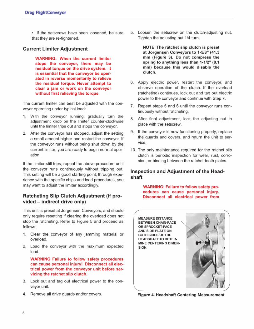
Figure 4. Headshaft Centering Measurement
6
MEASURE DISTANCE BETWEEN CHAIN-FACE OR SPROCKET-FACE AND SIDE PLATE ON BOTH SIDES OF THE HEADSHAFT TO DETER- MINE CENTERING DIMEN- SION.

Figure 5. Headshaft Take-Up Slot
the conveyor unit before removing the headshaft cover or servicing the head- shaft assembly.
Proceed as follows:
1. Lock out and tag out electrical power to the con- veyor unit.
2. Remove any drive system covers.
3. On indirect drive units, move the drive motor/speed reducer assembly on its adjustment screws to relieve tension on the roller chain.
4. Disconnect the master link from the roller chain and remove the chain from the headshaft drive sprocket. Remove covers, as necessary, to expose the headshaft.
5. The headshaft can be now be inspected as follows:
A. If the drag chain runs against the sides of the conveyor or wanders from side to side:
a). Measure the distance between the headshaft sprocket face (or chain face) and the inside of the sidewall on both ends of the shaft to verify that the drag chain is centered in the discharge section (Figure 4). If not, proceed as follows:
• Loosen the setscrews on the flange bearing or pillow block bearing so that the headshaft can be moved laterally. (See Figure 5.)
• Move the shaft and sprocket towards the side of the machine having the greatest clearance.
• Measure the distance between the chain face (or sprocket face) and the inside of the sidewall (Figure 4). Be sure that the sprockets are cen- tered (distance is equal for both sides).
• Retighten the bearing block setscrews.
b). If the chain still runs against the side of the con- veyor, or if the chain climbs the sprockets:
• Measure the distance between the bearing and the front edge of the sidewall (Figure 6) to verify that the headshaft is not cocked.
• If the shaft is skewed, loosen the bearing block mounting carriage bolts on the lagging side and, using the take-up device, balance the position of the headshaft in the discharge section.
• Tighten the bearing block bolts.
c). If the drag chain climbs the sprockets even after steps (a) and (b) have been completed, chain ten- sion may be too loose. Check drag chain tension as described under “Drag Chain Tension” below.
B. If the driven sprocket turns but the headshaft does not, check the drive key on the driven sprocket to ensure that it is not sheared. If the key is not sheared, check the headshaft shear pin, if provided (see Figure 7).
C. If the headshaft turns, but the chain does not move, inspect the headshaft sprocket pins or keys.
Figure 6. Checking for Headshaft Skew
7
TAKE-UP BOLT
HEADSHAFTTAKE-UP SLOT SETSCREW
BEARING MOUNTING CARRIAGE BOLT

Figure 7. Driven Sprocket Shear Pin and Drive Key
See Figure 8. (In some cases, a sprocket key is used instead of a pin.) If the pins or keys are dam- aged, refer to “Removal of Headshaft Assembly” below.
D. If the headshaft has lateral movement in the bearings: Check the headshaft-bearing mounting carriage bolts for tightness (Figure 5). If either is loose, proceed as follows:
• Adjust the headshaft so that the drag chain is equal distant between the chain and the inside of the side plate on each side (Figure 5).
• Tighten the headshaft-bearing mounting car- riage bolts.
E. Headshaft is seized and does not rotate: refer to “Removal of Headshaft” below.
6. Reinstall the roller chain, and adjust tension (indi- rect drive).
7. Reinstall all covers and shrouds.
8. Apply electrical power.
Figure 8. Headshaft Sprocket Pin
Headshaft Shear Pin Replacement (if pro- vided – indirect drive only) Refer to Figure 7 and proceed as follows:
WARNING: Failure to follow safety pro- cedures can cause personal injury. Disconnect all electrical power from the conveyor unit before removing the headshaft cover or servicing the head- shaft assembly.
1. Lock out and tag out electrical power to the con-
veyor unit.
2. Remove all covers and shrouds covering the drive system.
3. Move the drive motor forward on its adjustment screws to relieve tension on the roller chain.
4. Disconnect the master link from the roller chain and remove the roller chain from the headshaft drive sprocket.
5. Loosen the bearing mounting carriage bolts.
6. From the discharge section, push the headshaft toward the tail to relieve tension on the drag chain.
7. Remove any pieces of the broken shear pin from the driving and driven members of the hub.
8. Align the driving and driven members of the hub, and insert the replacement shear pin.
9. Verify that the replacement shear pin is correctly aligned in the hub.
10. Using the take-up device, apply tension to the con- veyor drag chain. (See “Drag Chain Tension Adjustment” below.)
11. Tighten the bearing mounting carriage bolts to pre- vent headshaft movement.
12. Reinstall the drive safety covers and guards over the drive system.
13. Reinstall the roller chain and adjust the drive motor chain tension as described under “Drive Chain Adjustment.”
14. Apply electrical power to the unit. Drag Chain Tension Adjustment Proceed as follows:
1. Conveyor chains eventually "stretch" with operation so that tension must occasionally be adjusted using
8
SHEAR PIN DRIVE KEY
SPROCKET PIN

Figure 9. Direct Drive and Take-Up Mechanisms
Figure 10. Indirect Drive and Take-Up Mechanisms
the take-up mechanism as follows: (Refer to Fig- ures 9 and 10.)
• Lock out and tag out the conveyor.
• Remove covers and guards.
• Loosen the jam nuts and take-up bolts.
NOTE: On indirect drive units, remove the roller chain between the speed reducer and headshaft sprocket to free the headshaft for movement using the take-up device. Remove the master link on the roller chain to remove the chain.
• Adjust the take-up bolts to shift the headshaft in the required direction to increase or decrease tension. Be sure that both sides are tensioned
uniformly so that the headshaft is not askew, which would increase wear on the chains and sprockets. (See Figure 6.)
WARNING: Never check chain tension using your hand while the conveyor is operating. Failure to observe this warning can result in severe injury to your hand.
• Check drag chain tension approximately mid- way in the load section by lifting each chain from the bottom of the load section (Figure 11). Chain slack at this position should be approximately 25 to 38 mm (1 to 1-1/2 inch).
• Tighten the take-up retaining bolts and jam nuts.
• Remove the tagout and restart the conveyor. Allow the conveyor to operate for 15 minutes and
9
ADD GEAR MOTOR PHOTO
TAKE-UP BOLT JAM NUT SPEED REDUCER DRIVE MOTOR JAM NUT
FLANGE BEARING TAKE-UP BOLT
TAKE-UP BOLT DRIVE MOTOR JAM NUT
TAKE-UP BOLT
BEARING / PILLOW BLOCK JAM NUT

observe that the chain does not drift sideways, which would indicate skewing.
• Install and secure all covers and guards.
2. Check the sprockets annually for indications of wear.
3. Check conveyor drag chain every six months for indications of wear and damage.
4. Check the tail hubs (or sprockets on larger units) for wear. (See Figure 12.) Normally, this is not a problem and need only be performed when the conveyor is being completely disassembled for other reasons.
5. Verify that all casing bolts are tight and verify the general condition of the casing every six months.
Figure 11. Checking Drag Chain Tension
6. It is recommended that the conveyor drag chain be removed annually to clean the casing and to check the tracks for wear and damage.
Replacing the Headshaft Removal of Headshaft Assembly. Proceed as fol- lows:
1. Carefully jog the conveyor until a drag chain pin is accessible through the take-up slots (Figure 13).
WARNING: Failure to follow safety pro- cedures can cause personal injury. Disconnect all electrical power from the conveyor unit before removing the headshaft cover or servicing the head- shaft assembly.
2. Lock out and tag out electrical power to the con-
veyor unit.
3. Remove all necessary covers and shrouds.
4. On the direct drive system remove the drive motor/ speed reducer assembly.
NOTE: On indirect drive units, remove the roller chain between the speed reducer and driven sprocket to free the headshaft for movement. Remove the master link on the roller chain to remove the chain.
5. Loosen the jam nuts and take-up bolts, and loosen
the bearing mounting carriage bolts.
NOTE: If the unit is equipped with a ratchet slip clutch, loosen the set- screw on the clutch hub and remove the slip clutch.
Figure 12. Tail Hub Figure 13. Pin Removal
10
TAKE MEASUREMENT MIDWAY ALONG THE LOAD SECTION. SLACK SHOULD BE BETWEEN 1 AND 1-1/2 INCHES (26 AND 38 MM).
REMOVE COTTER PIN AND ROLLER
BEARING SETSCREW
PIN SIDE WINGS TAIL HUB

6. At the discharge section, push the headshaft toward the tail to relieve tension on the drag chain.
7. Remove the cotter pin from both sides of the drag chain axle (Figure 13), and remove the chain pins, rollers, side wings and side bars to disconnect the drag chain assembly.
8. Install the chain pins, rollers side wings and side bars back in the top portion of the drag chain assembly to avoid loosing the parts.
9. Facing the discharge opening, pull the lower run of the drag chain out of the discharge section until the upper run of the drag chain clears the headshaft; lower the lower run of the drag chain to rest on the upper curve.
10. Loosen the setscrews securing the bearings to the headshaft (Figure 13).
11. Remove the non-drive side bearing from the head- shaft.
12. Remove the driven sprocket from the drive side of the conveyor by removing the setscrew in the sprocket hub.
13. Via the discharge opening, drive out the sprocket pin on the drive end of the headshaft (Figure 14), or remove the key, and slide the sprocket toward the non-drive side of the headshaft.
14. Push the headshaft towards the drive side, moving it out of the non-drive side bearing plate. Then lower the non-drive end of the headshaft and remove the entire headshaft to a safe working area.
Installing Headshaft Assembly. Installation of the headshaft assembly is basically the reverse of the removal process. Upon completion of installation, refer to “Drag Chain Tension Adjustment” below to complete installation. 1. Slide the headshaft into the drive side of the con-
veyor and then into the non-drive side.
2. Drive the press-fit sprocket pin into the hole pro- vided in the headshaft (Figure 15), or install the sprocket key if the unit is so equipped.
3. Install the bearings and bearing blocks/flanges and the sprocket/ratcheting slip clutch on the headshaft. Install the clutch-hub-mounting setscrew, but do not tighten the bearing block mounting carriage bolts at this time.
4. Refer to “Inspection and Adjustment of the Head- shaft,” above, and center the sprocket/headshaft assembly in the conveyor.
5. After the sprocket has been aligned, tighten the bearing block and/or flange mounting carriage bolts.
6. Reinstall the drag chain over the headshaft and secure it with the appropriate items. (See Steps 6 through 8 on page 12 under “Installation.”)
7. Operate the conveyor for approximately 15 minutes to verify correct alignment.
Drag Chain Removal and Installation Removal. Proceed as follows:
1. Carefully jog the conveyor until a drag chain pin is accessible through the take-up slots (Figure 13).
WARNING: Failure to follow safety pro- cedures can cause personal injury. Disconnect all electrical power from the conveyor unit before removing the headshaft cover or servicing the head- shaft assembly.
Figure 14. Removing the Sprocket Pin Figure 15. Installing the Headshaft
11
SPROCKET PIN
DRIVE OUT SPROCKET PIN AND SLIDE THE SPROCKET TOWARD THE NON-DRIVE END OF THE DRIVE SHAFT

2. Lock out and tag out electrical power to the con-
veyor unit.
3. Remove all necessary covers and shrouds.
4. On the direct drive unit, remove the drive motor/ speed reducer assembly.
NOTE: On indirect drive units, remove the roller chain between the speed reducer and headshaft sprocket to free the headshaft for movement. Remove the master link on the roller chain to remove the chain.
5. Loosen the jam nuts and take-up bolts.
6. Loosen the bearing mounting carriage bolts.
7. At the discharge section, push the headshaft toward the tail to relieve tension on the drag chain.
NOTE: In the following instructions, the drag chain will be removed and lowered to the floor. This may require two persons or even an overhead lift.
8. At the take-up slots (Figure 13), remove the cotter
pins from both sides of the drag chain assembly (axle), then remove the chain pins and rollers to disconnect the drag chain assembly.
9. Install the chain pins and rollers back in the top portion of the drag chain assembly to avoid loosing the parts.
10. Facing the discharge opening, pull on the lower half of the drag chain and remove it entirely from the discharge section. Lower the chain and allow it to fold on the floor beneath the discharge section.
11. Remove all foreign objects from the casing.
12. Inspect the drag chain assembly and casing for worn or damaged parts and repair/replace as required.
Installation
Installing the drag chain assembly is essentially the reverse procedure discussed under “Removal.” Pro- ceed as follows:
1. Be sure that the headshaft is pushed all the way back.
2. Feed the end of the drag chain assembly into the lower run of the conveyor casing through the dis- charge section. See Figure 16. Be sure that the
Figure 16. Installing the Drag Chain
wings face downward; i.e. the bottom of the con- veyor.
3. Feed (push) the drag chain assembly through the casing, past the tail hub, and up the incline until it comes up to the headshaft sprockets.
4. Pull the top run of the drag chain assembly over the headshaft until the end is centered in the take-up slots.
5. Pull the bottom run of the drag chain assembly to remove any slack.
6. Re-install the chain pins, rollers, or pins through the take-up slots.
7. The drag chain pins are relatively easy to install. Install the rollers, pins, side wings, and side bars on each side. On larger conveyors, the roller pins are held in position with cotter pins. Smaller units may use pins that are press fit, which requires the use of pliers or vice grip.
8. Be sure that all drag chain assembly parts are in their proper position.
9. Reinstall the drive motor/reducer assembly, or roller chain (indirect drive), and adjust tension at the headshaft using the take-up bolts and jam nuts as described under “Drag Chain Tension Adjustment.”
10. Secure the pillow block mounting carriage bolts.
11. Operate the conveyor for approximately 15 minutes to observe and confirm trouble-free operation before placing the unit in service.
12
FEED DRAG CHAIN INTO LOWER RUN OF THE CONVEYOR CASING.

LUBRICATION
Grease Lubrication
There are a total of 2 grease fittings that require lubri- cation – one on either end of the headshaft to lubricate the headshaft bearings. (See Figure 17.) Grease all bearings as follows.
For normal operating conditions, apply No. 2 grease through the grease fittings every 90 days. Grease should conform to NLGI No. 2 consistency, and should be free of chemical impurities such as free acid or alkali, and mechanical impurities such as dust, rust, metal particles, or abrasives. Add grease slowly until a slight bead forms between the seals.
Oil Lubrication
• The roller chain should be brushed with light- weight oil at regular intervals.
• The speed reducer on the direct drive unit is fac- tory lubricated and sealed. It therefore requires not further lubrication.
Figure 17. Grease Fitting Location
• The indirect drive speed reducer may require periodic oil changes. Check instructions on the reducer.
NOTE: When changing oil in a double- reduction unit, be sure the primary and secondary chambers are both changed.
Table 2. Suggested Speed Reducer Lubricants
MANUFACTURER AMBIENT TEMPERATURE
15 to 60°F 50 to 125°F
KLUBER KLUBERSYN UH1-640 KLUBERSYN UH1-640
CHEVRON Cylinder 460X Cylinder Oil - 680X
EXXON Cylesstic TK460 Cylesstic TK680
GULF Senate 460 Senate 680D
MOBIL 600W Super Extra Hecla Super
SHELL Valvata Oil Jz460 Valvata Oil J680
SUN Gear Oil 7C Gear Oil 8C
TEXACO Honor Cyl. Oil 650T Cyl. Oil
UNOCAL Steaval A Worm Gear 140
Compound AGMA 7 AGMA 8
13
ONE GREASE FITTING ON THE BEARING SIDE OF THE UNIT

TROUBLESHOOTING
PROBLEM PROBABLE CAUSE REMEDY
Unit does not operate. Blown fuse. Replace Fuse. Determine cause and correct.
Tripped overload relay(s). Determine cause and correct. Reset relay.
Main disconnect off. Turn main disconnect on.
No power to line side of discon- nect.
Determine reason for no power and correct.
Excessive wear on chain or cas- ing,
Conveyor not level or plumb. Level and plumb conveyor.
Chain assembly misaligned or incorrect tension.
Align chain and/or correct ten- sion. See Maintenance Section of this manual.
Damaged or missing chain assembly parts.
Repair or replace chain.
Clutch ratcheting or slipping. Chain misaligned or incorrect tension.
Align chain and/or correct ten- sion. See Maintenance Section of this manual.
Excessive or accumulated load- ing.
Avoid load buildup by running conveyor continuously. Do not manually surge material unto conveyor.
Carry-back of material into conveyor.
Collection receptacle full. Replace/empty receptacle as required.
Incorrect clutch tension. Refer to clutch section of this manual.
Damaged chain. Repair or replace chain.
Accumulation of conveyed material or foreign objects inside casing.
Clean out conveyor.
More Troubleshooting on Next Page
14

PROBLEM PROBABLE CAUSE REMEDY
Excessive wear on chain or cas- ing
Conveyor not level or plumb. Level and plumb conveyor.
Chain assembly misaligned or incorrect tension.
Align chain and/or correct ten- sion. See Maintenance Section of this manual.
Carry-back of material into conveyor.
Collection receptacle full. Replace/empty receptacle as required.
Damaged chain. Repair or replace chain.
Accumulation of conveyed material or foreign objects inside casing.
Clean out conveyor.
Chain pulses or surges. Chain assembly misaligned or incorrect tension.
Align chain and/or correct ten- sion. See Maintenance Section of this manual.
Carry-back of material into conveyor.
Collection receptacle full. Replace/empty receptacle as required.
Damaged chain. Repair or replace chain.
Accumulation of conveyed material or foreign objects inside casing.
Clean out conveyor.
15

WARRANTY
Jorgensen Conveyors, Inc. guarantees the material of our manufacture against defects in material or workmanship under normal and proper use for one year in service or eighteen months from shipment, whichever occurs first. Material which we purchase can be guaranteed by use only to the extent of the original manufacturer’s guarantee. We shall not be held liable for damages or delay caused by defective material, or contingent claims of any kind arising from loss of production owing to failure of shipment. Our obligation under this warranty is limited to furnishing new or replacing defective material without charge f.o.b. factory. No allowance will be made for repairs or alterations unless made with our written consent.
Caution should be used in the care and application of our products as the guarantee recited above does not apply where lack of proper maintenance or misapplication exists. We will not be liable for improper storage or handling of our products prior to placement in service.
The within equipment will be specifically designed and manufactured for and will be sold to purchaser for the sole purpose of transporting and conveying raw materials, work in process and finished goods of purchaser. Purchaser does hereby agree to exonerate, indemnify, defend and hold seller harmless of and from all loss, liability and damages which may be suffered by or asserted against the seller, and all costs and expenses which seller may incur because of any claim or claims which may be asserted against seller by any person for death or injury to anyone sustained while riding or attempting to ride upon said equipment.
JORGENSEN CONVEYORS, INC. • 10303 N. Baehr Road • Mequon, Wisconsin 53092-0156 P.O. Box 09156
Phone: 262-242-3089
Fax: 262-242-4382
www.jorgensenconveyors.com
Document No. 93-07, Rev. 0816