operational it and telecoms strategy - sp energy …...35 sp energy networks 2015–2023 business...
TRANSCRIPT
35
SP Energy Networks 2015–2023 Business Plan Updated March 2014
Annex Operational IT and Telecoms StrategySP Energy Networks March 2014
Operational IT and Telecoms March 2014
Issue Date Issue No. Document Owner Amendment Details
17th March 2014 1.0 P. Dolan First Issue

Operational IT and Telecoms
1. Scope 3
2. Table of linkages 3
3. Overview 4
4. Substation RTUs, marshalling kiosks, receivers 5
4.1. RTU Replacement 5 4.2. Secondary Control Equipment Modernisation 8 4.3. System Monitoring Equipment 9
5. Control Centre Hardware and Software 10
5.1. Annual Updates to Central System Software 10 5.2. Data Servers and Software Modernisation 11 5.3. Hardware and Control Centre Infrastructure 11 5.4. Control Centre Modernisation 11 5.5. Central System Software Major Upgrade 11
6. Communications for switching & monitoring 12
6.1. Scanning Telemetry Modernisation 12 6.2. Service Requirement changes 13 6.3. Active and Ancillary Equipment Modernisation 16
7. Smart Grid Enablers 17 7.1. Control System and Communications Overall Design Aims 19 7.2. Control System and Communications Development Core
Objectives 20
2

Operational IT and Telecoms
1. Scope This Annex covers our Operational IT and Telecoms portfolio. It should be read in conjunction with the following additional annexes to obtain an overall picture of our IT & Telecoms Strategy.
• Non-Operational IT and Telecoms Strategy
• Smart Metering Strategy
• Smart Grid Strategy
2. Table of linkages This strategy supports our ED1 Business Plan. For ease of navigation, the following table links this strategy to other relevant parts of our plan.
Document Chapter / Section
SP Energy Networks Business Plan 2015-2023 Chapter C6 - Expenditure
SP Energy Networks Business Plan 2015-2023 Annexes
Annex C6 – Expenditure Supplementary Annex
Section 8.3.9
SP Energy Networks Business Plan 2015-2023 Annexes
Annex C6 – Cost Benefit Analysis – SPEN
Reference 57
SP Energy Networks Business Plan 2015-2023 Annexes
Annex C6 – Protective Equipment and Supporting Systems Strategy – SPEN
Section 7.2
SP Energy Networks Business Plan 2015-2023 Annexes
Annex C6 – Protective Equipment and Supporting Systems Strategy – SPEN
Section 4.4
SP Energy Networks Business Plan 2015-2023 Annexes
Annex C6 – SP Manweb Company Specific Factors – SPEN
Section B3
SP Energy Networks Business Plan 2015-2023 Annexes
Annex C7 – Smart Grid Strategy – Creating a Network for the Future – SPEN
Section 7.2
3
Operational IT and Telecoms
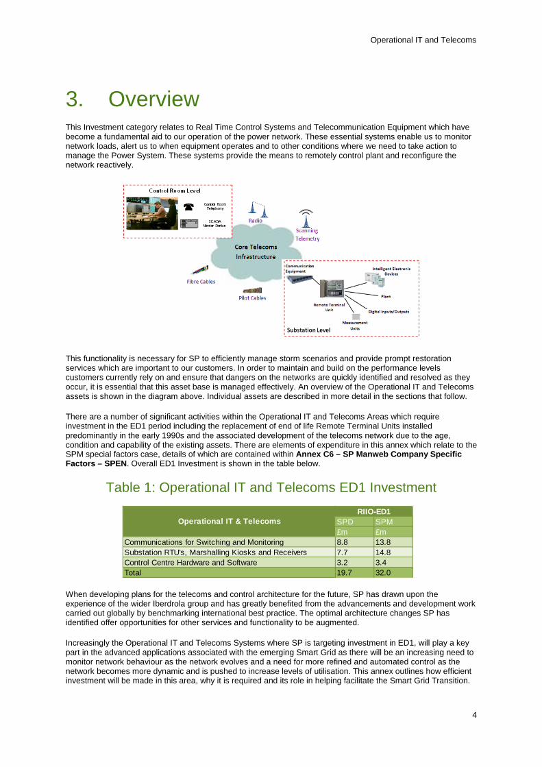
3. Overview This Investment category relates to Real Time Control Systems and Telecommunication Equipment which have become a fundamental aid to our operation of the power network. These essential systems enable us to monitor network loads, alert us to when equipment operates and to other conditions where we need to take action to manage the Power System. These systems provide the means to remotely control plant and reconfigure the network reactively.
This functionality is necessary for SP to efficiently manage storm scenarios and provide prompt restoration services which are important to our customers. In order to maintain and build on the performance levels customers currently rely on and ensure that dangers on the networks are quickly identified and resolved as they occur, it is essential that this asset base is managed effectively. An overview of the Operational IT and Telecoms assets is shown in the diagram above. Individual assets are described in more detail in the sections that follow.
There are a number of significant activities within the Operational IT and Telecoms Areas which require investment in the ED1 period including the replacement of end of life Remote Terminal Units installed predominantly in the early 1990s and the associated development of the telecoms network due to the age, condition and capability of the existing assets. There are elements of expenditure in this annex which relate to the SPM special factors case, details of which are contained within Annex C6 – SP Manweb Company Specific Factors – SPEN. Overall ED1 Investment is shown in the table below.
Table 1: Operational IT and Telecoms ED1 Investment
SPD SPM£m £m
Communications for Switching and Monitoring 8.8 13.8Substation RTU's, Marshalling Kiosks and Receivers 7.7 14.8Control Centre Hardware and Software 3.2 3.4Total 19.7 32.0
Operational IT & TelecomsRIIO-ED1
When developing plans for the telecoms and control architecture for the future, SP has drawn upon the experience of the wider Iberdrola group and has greatly benefited from the advancements and development work carried out globally by benchmarking international best practice. The optimal architecture changes SP has identified offer opportunities for other services and functionality to be augmented.
Increasingly the Operational IT and Telecoms Systems where SP is targeting investment in ED1, will play a key part in the advanced applications associated with the emerging Smart Grid as there will be an increasing need to monitor network behaviour as the network evolves and a need for more refined and automated control as the network becomes more dynamic and is pushed to increase levels of utilisation. This annex outlines how efficient investment will be made in this area, why it is required and its role in helping facilitate the Smart Grid Transition.
4
Operational IT and Telecoms
4. Substation RTUs, marshalling kiosks, receivers
Our plans for investment during the ED1 period include replacement programmes for end of life Grid and Primary Remote Terminal Units, Secondary Control Systems and monitoring equipment. The biggest investment activity in this area is replacement of Grid (SPM only) and Primary Remote Terminal Units (RTUs) which represents 87% of the investment in the area in SPM and 71% of in the investment in SPD.
Investment associated with Substation RTUs, marshalling kiosks, receivers is shown in the table below.
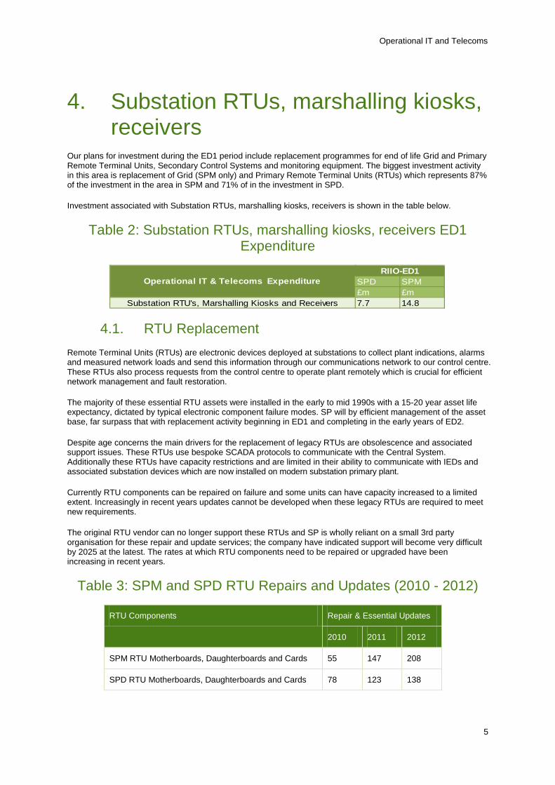
Table 2: Substation RTUs, marshalling kiosks, receivers ED1 Expenditure
SPD SPM£m £m
Substation RTU's, Marshalling Kiosks and Receivers 7.7 14.8
Operational IT & Telecoms ExpenditureRIIO-ED1
4.1. RTU Replacement Remote Terminal Units (RTUs) are electronic devices deployed at substations to collect plant indications, alarms and measured network loads and send this information through our communications network to our control centre. These RTUs also process requests from the control centre to operate plant remotely which is crucial for efficient network management and fault restoration.
The majority of these essential RTU assets were installed in the early to mid 1990s with a 15-20 year asset life expectancy, dictated by typical electronic component failure modes. SP will by efficient management of the asset base, far surpass that with replacement activity beginning in ED1 and completing in the early years of ED2.
Despite age concerns the main drivers for the replacement of legacy RTUs are obsolescence and associated support issues. These RTUs use bespoke SCADA protocols to communicate with the Central System. Additionally these RTUs have capacity restrictions and are limited in their ability to communicate with IEDs and associated substation devices which are now installed on modern substation primary plant.
Currently RTU components can be repaired on failure and some units can have capacity increased to a limited extent. Increasingly in recent years updates cannot be developed when these legacy RTUs are required to meet new requirements.
The original RTU vendor can no longer support these RTUs and SP is wholly reliant on a small 3rd party organisation for these repair and update services; the company have indicated support will become very difficult by 2025 at the latest. The rates at which RTU components need to be repaired or upgraded have been increasing in recent years.
Table 3: SPM and SPD RTU Repairs and Updates (2010 - 2012)
RTU Components Repair & Essential Updates
2010 2011 2012
SPM RTU Motherboards, Daughterboards and Cards 55 147 208
SPD RTU Motherboards, Daughterboards and Cards 78 123 138
5

Operational IT and Telecoms
The increased reliance on a small specialist company to support an aging population of obsolete RTUs is a current business risk. This position is unsustainable as an ongoing model and the current population of RTUs must be replaced over the medium term.
The replacement programme for these RTUs will commence in the ED1 period and will be completed in the early years of ED2. Replacing RTUs over a prolonged period is the preferred strategy as it allows adequate time for the telecoms network to be developed in an efficient manner in line with requirements. Early investment is avoided as the current RTU population will be supported using healthy spares recovered as part of the replacement programme.
The liberated spares will help prolong the asset life of current RTUs although not indefinitely as both the RTUs and spares are already in an aged condition.
Replacement RTUs will be capable of supporting the most common industry protocols and international standards as this will help ensure that the assets can be supported for the longest period possible and will reduce the risks associated with limited supplier dependence.
Vendor Specific Protocols will no longer be used. RTUs will also be capable of supporting hardwired I/O as this is the defacto arrangement for the majority of existing substation plant installations
Figure 1: Proposed Substation Architecture Development
The move to modern protocol RTUs requires development of the telecoms infrastructure due to higher bandwidth requirements and considerations associated with transporting different protocols on shared telecoms infrastructure and the current RTU’s active role in transmitting and receiving data for multiple remote devices.
Over the ED1 period, SP will move to an IP based communications network utilising standard protocols. This migration requires significant development of the operational telecoms infrastructure as legacy slow speed serial links are replaced by higher speed IP infrastructure. These development requirements and associated investments are detailed in the “Communications for switching & monitoring” section of the narrative.
It is possible to carry out bespoke development works to enable legacy protocols on modern RTU offerings which would reduce telecoms networks development work however this would add significant development costs and again limit available solutions. Without the move to industry standard equipment, RTU costs would remain extremely high (both to SP and 3rd parties wishing to connect to our network) in comparison to industry averages and the company would be unable to share the benefits of innovation in this market. Additionally this would impose limitations which would impact our ability to develop more advanced network control systems capability and other smart grid initiatives.
A Cost Benefit Analysis (CBA), C6 – Cost Benefit Analysis - SPEN, Reference 57 was carried out to benchmark the approach of buying RTUs which communicate using the latest generation of industry standard protocols over an IP network against procuring modern RTUs which have been customised to support legacy SPD and SPM protocols with minimal alteration to the telecoms network.
Although the initial capital investment of moving to industry standard RTUs per unit is greater due to associated telecoms upgrade costs, this approach is more sustainable over the long term than perpetuating legacy protocols, and also accesses a larger supplier cohort allowing more potential for cost reduction.
6
Operational IT and Telecoms
Perpetuation of legacy protocols is not a viable option long term due to the associated limited range of RTU suppliers and even more limited range of products on which the legacy protocols can still be supported. Accordingly the asset life achieved for new RTUs by moving to industry standard equipment is forecast to be greater due to support difficulties associated with a bespoke RTU solution. This has in turn influenced our decision to defer some of the RTU replacement activity into ED2 which would be extremely difficult to manage if support difficulties were experienced with bespoke solutions installed.
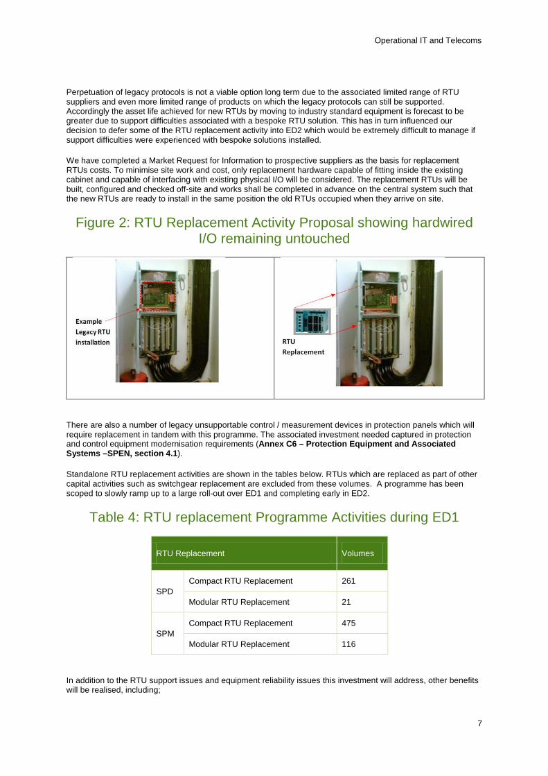
We have completed a Market Request for Information to prospective suppliers as the basis for replacement RTUs costs. To minimise site work and cost, only replacement hardware capable of fitting inside the existing cabinet and capable of interfacing with existing physical I/O will be considered. The replacement RTUs will be built, configured and checked off-site and works shall be completed in advance on the central system such that the new RTUs are ready to install in the same position the old RTUs occupied when they arrive on site.
Figure 2: RTU Replacement Activity Proposal showing hardwired I/O remaining untouched
There are also a number of legacy unsupportable control / measurement devices in protection panels which will require replacement in tandem with this programme. The associated investment needed captured in protection and control equipment modernisation requirements (Annex C6 – Protection Equipment and Associated Systems –SPEN, section 4.1).
Standalone RTU replacement activities are shown in the tables below. RTUs which are replaced as part of other capital activities such as switchgear replacement are excluded from these volumes. A programme has been scoped to slowly ramp up to a large roll-out over ED1 and completing early in ED2.
Table 4: RTU replacement Programme Activities during ED1
RTU Replacement Volumes
SPD Compact RTU Replacement 261
Modular RTU Replacement 21
SPM Compact RTU Replacement 475
Modular RTU Replacement 116
In addition to the RTU support issues and equipment reliability issues this investment will address, other benefits will be realised, including;
7

Operational IT and Telecoms
• Delivery of equipment supporting international standards for device inter-communication
• Elimination of the dependence on single or restricted supplier choices
• Faster cheaper integration of new equipment into control systems
• Potential to enhance control functionality and deploy smart grid applications remotely within the network.
4.2. Secondary Control Equipment Modernisation We plan to replace end of life secondary control equipment towards the end of the ED1 period starting with the first of the secondary tele-controlled systems installed between 2003 and 2004. This equipment is used for remotely controlling switchgear installed in secondary substations and on overhead lines to minimise the impact of customer’s interruptions by enabling fast reconfiguration of the network.
Associated RTUs are much less complex and lower cost than the systems deployed in Grid and Primary substations. The life expectancy of these products is also expected to be much less than control equipment in Grid and Primary substations in part due to the much harsher environment that they are required to operate. Equipment inspections have confirmed some component corrosion which is being monitored.
The primary driver for replacement activities to commence in ED1 is equipment support and parts availability. The equipment vendor has ceased trading and the key control components are no longer manufactured. Spare components availability is limited so earliest generation replacement is being replaced to reduce risk. All useable spares will be recovered to support existing asset base.
It is essential that this equipment is replaced before failure, as it is integral to ensuring current levels of network performance are maintained. The table below shows the volumes of the main investment activities in this area, secondary control RTU and Radio Repeaters. There is also an investment requirement for ancillary equipment such as batteries and actuators in this area which are not detailed in this table.
Table 5: Secondary Control Equipment Modernisation during ED1
Secondary Control Equipment Volumes
SPD Secondary Control - RTU Modernisation 185
Secondary Control - Radio Repeaters Modernisation 110
SPM Secondary Control - RTU Modernisation 115
Secondary Control - Radio Repeaters Modernisation 85
8
Operational IT and Telecoms
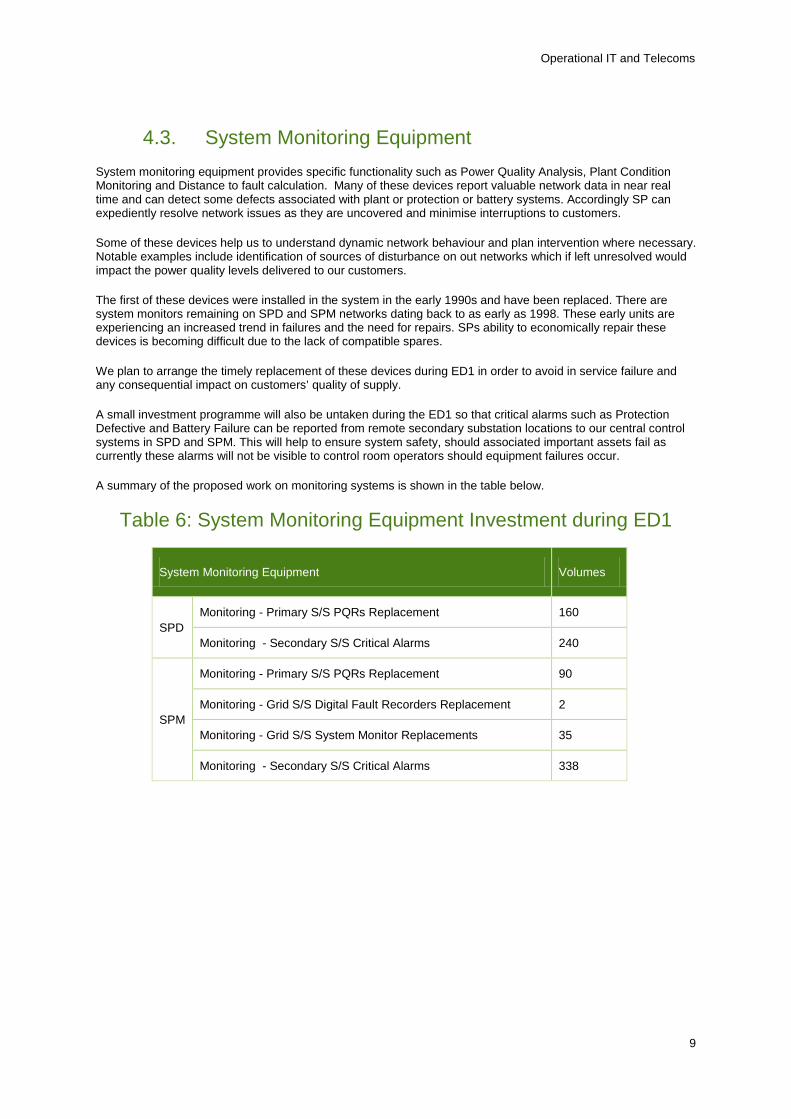
4.3. System Monitoring Equipment System monitoring equipment provides specific functionality such as Power Quality Analysis, Plant Condition Monitoring and Distance to fault calculation. Many of these devices report valuable network data in near real time and can detect some defects associated with plant or protection or battery systems. Accordingly SP can expediently resolve network issues as they are uncovered and minimise interruptions to customers.
Some of these devices help us to understand dynamic network behaviour and plan intervention where necessary. Notable examples include identification of sources of disturbance on out networks which if left unresolved would impact the power quality levels delivered to our customers.
The first of these devices were installed in the system in the early 1990s and have been replaced. There are system monitors remaining on SPD and SPM networks dating back to as early as 1998. These early units are experiencing an increased trend in failures and the need for repairs. SPs ability to economically repair these devices is becoming difficult due to the lack of compatible spares.
We plan to arrange the timely replacement of these devices during ED1 in order to avoid in service failure and any consequential impact on customers’ quality of supply.
A small investment programme will also be untaken during the ED1 so that critical alarms such as Protection Defective and Battery Failure can be reported from remote secondary substation locations to our central control systems in SPD and SPM. This will help to ensure system safety, should associated important assets fail as currently these alarms will not be visible to control room operators should equipment failures occur.
A summary of the proposed work on monitoring systems is shown in the table below.
Table 6: System Monitoring Equipment Investment during ED1
System Monitoring Equipment Volumes
SPD Monitoring - Primary S/S PQRs Replacement 160
Monitoring - Secondary S/S Critical Alarms 240
SPM
Monitoring - Primary S/S PQRs Replacement 90
Monitoring - Grid S/S Digital Fault Recorders Replacement 2
Monitoring - Grid S/S System Monitor Replacements 35
Monitoring - Secondary S/S Critical Alarms 338
9
Operational IT and Telecoms
5. Control Centre Hardware and Software
Whilst RTUs and associated communications infrastructure are essential to the control and operation of individual sites, the Central Control System gathers data from RTUs from every site where they are deployed and then presents this information to operators in a format from which they can quickly understand behaviour on the network and react accordingly. The central control system also allows operators to remotely control equipment connected to the SCADA systems.
Accordingly these systems are of high strategic importance to the operation of the business and require regular investment to remain both current and supportable. This is an area where change is rapid, both in terms of vendors obsolescing products and withdrawing support at the same time as user requirements changing due to network evolution and introduction of new products on the network (plant & protection).
Investment in this area is focused on the following activities;
• Annual Updates to Central System Application Software
• Data Servers and Software Modernisation
• Investment in Hardware and Control Centre Infrastructure
• Control Centre Modernisation
• Major Upgrade of the Central System Software
Investment associated with Control Centre Hardware and Software is shown in the table below.
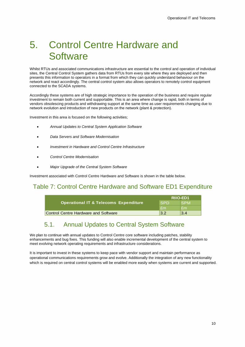
Table 7: Control Centre Hardware and Software ED1 Expenditure
SPD SPM£m £m
Control Centre Hardware and Software 3.2 3.4
Operational IT & Telecoms ExpenditureRIIO-ED1
5.1. Annual Updates to Central System Software We plan to continue with annual updates to Control Centre core software including patches, stability enhancements and bug fixes. This funding will also enable incremental development of the central system to meet evolving network operating requirements and infrastructure considerations.
It is important to invest in these systems to keep pace with vendor support and maintain performance as operational communications requirements grow and evolve. Additionally the integration of any new functionality which is required on central control systems will be enabled more easily when systems are current and supported.
10
Operational IT and Telecoms
5.2. Data Servers and Software Modernisation Whilst Annual updates will address core software modules in the main SCADA system there will be a need to keep pace with certain other third party software products in order to maintain currency with supported and secure versions.
Due to growth in the network and volume of incidents and events, some servers, particularly those which hold transactional data, will require expansion of their capacity and increase in their processing power within their expected lifetime in order to maintain acceptable response times for users.
A refresh of the data historian system is scheduled over the ED1 period. Costs attributable to smart metering have been detailed separately however we are looking to integrate the various data streams from the network and smart metering to maximise the potential business benefit.
5.3. Hardware and Control Centre Infrastructure Investment in hardware such as servers is required to ensure critical infrastructure remains within the fully supported range, increasing age-related failure effects are avoided and optimal performance is realised. This will also ensure opportunities remain open to augment the control system with additional functionality as it is required, and to best utilise additional functionality provided in software upgrades.
As a result of expected increased utilisation of the control system and characteristics of industry standard protocols in ED1, extra demands will be placed upon the Front End Processors (FEPs) and top level communications network. In SP-M, due to the large number of SCADA outstations, this utilisation increase will drive control system architecture change such that FEPs will be distributed in strategic secured locations outside of the central control centre. Associated communications changes are detailed in section 6.2.
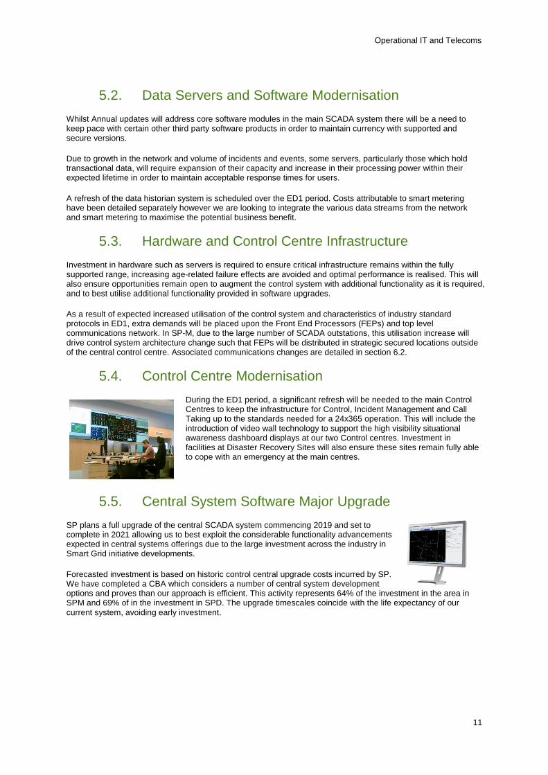
5.4. Control Centre Modernisation During the ED1 period, a significant refresh will be needed to the main Control Centres to keep the infrastructure for Control, Incident Management and Call Taking up to the standards needed for a 24x365 operation. This will include the introduction of video wall technology to support the high visibility situational awareness dashboard displays at our two Control centres. Investment in facilities at Disaster Recovery Sites will also ensure these sites remain fully able to cope with an emergency at the main centres.
5.5. Central System Software Major Upgrade SP plans a full upgrade of the central SCADA system commencing 2019 and set to complete in 2021 allowing us to best exploit the considerable functionality advancements expected in central systems offerings due to the large investment across the industry in Smart Grid initiative developments.
Forecasted investment is based on historic control central upgrade costs incurred by SP. We have completed a CBA which considers a number of central system development options and proves than our approach is efficient. This activity represents 64% of the investment in the area in SPM and 69% of in the investment in SPD. The upgrade timescales coincide with the life expectancy of our current system, avoiding early investment.
11
Operational IT and Telecoms
6. Communications for switching & monitoring
SP-D and SP-M operate private telecoms infrastructure comprising of SP owned assets in the form of copper pilot cables, fibre cables, point to point radio systems and scanning telemetry systems as well as 3rd party systems such as BT leased circuits. Investment in copper telecoms pilots and fibre assets are captured in asset replacement work programmes. BT leased line replacement investment requirements are captured in the BT21CN investment tables.
The telecoms networks which are build upon these assets are managed and utilised with the aid of active equipment such as Multiplexers, Switches and Routers. This network provides us with critical operational services used for Telephony, Protection and SCADA. The benefits SCADA systems afford to our customers are only possible with effectively managed telecoms infrastructure. This also applies to all protection services that utilise the telecoms network. Investment associated with active telecoms equipment used for managing the network and associated radio systems is captured in these investment programmes.
The volume of information coming from our power network will increase over ED1 placing additional demands on the telecoms systems due to RTU replacement activities and other emerging network applications. Increasing network service requirements are the main driver for an extensive communication networks update commencing in ED1 and completing in ED2. The telecoms upgrade which will rollout Ethernet services to Grid and Primary substations accounts for 83% of the investment total for SPM and 64% of the investment total for SPD. As the main driver for this investment is the RTU replacement activity, the associated investment is modelled in the same CBA (Annex C6 – Cost Benefit Analysis – SPEN, Reference 57). Consolidation of telecoms services onto managed infrastructure as part of this initiative will also ensure better management of faults and targeting of investment. The telecoms network update will greatly aid the Smart Grid transition as it will be possible to provision services for new applications readily on the new infrastructure established.
Other investment in this area will be used to replace obsolete, unmanaged, and unsupportable Active Telecoms Equipment (such as multiplexers), end of life Ancillary systems and Radio / Scanning Telemetry Assets.
Investment associated with Control Centre Hardware and Software is shown in the table below.
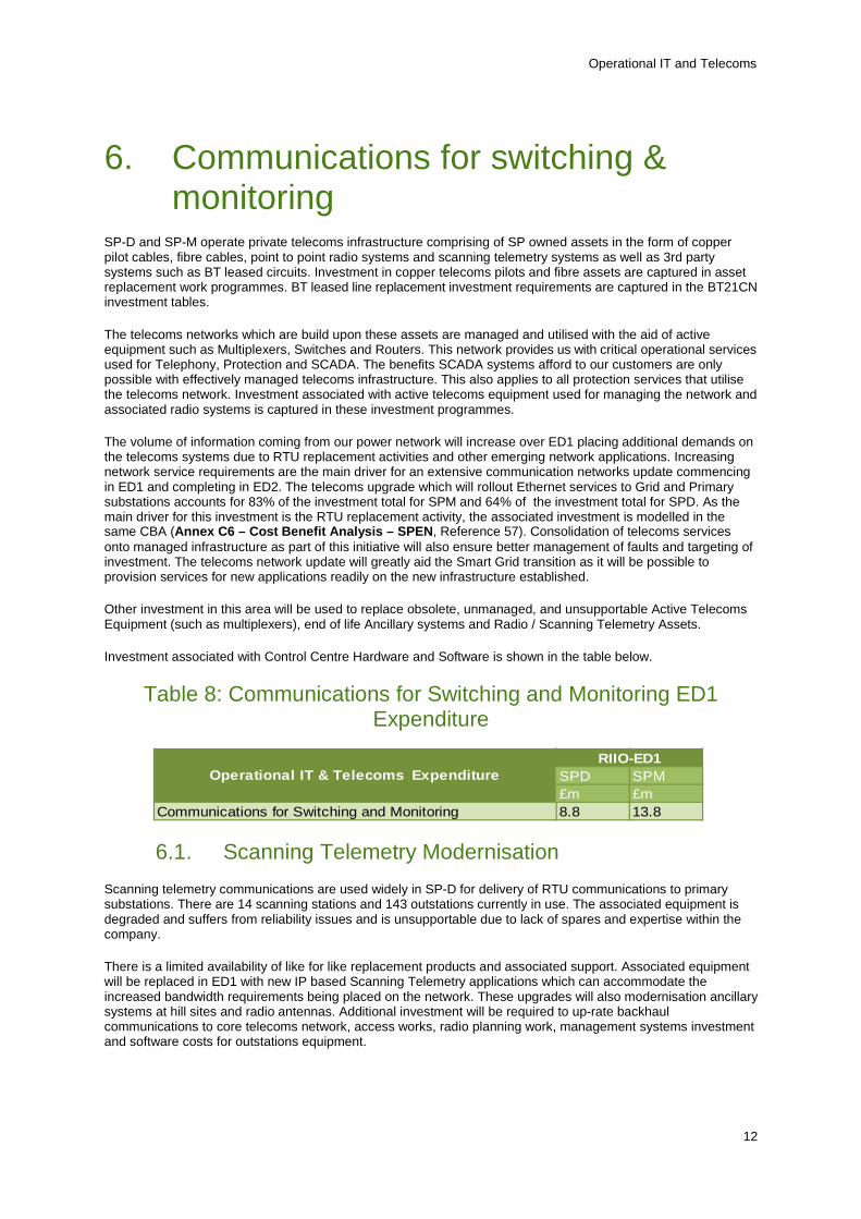
Table 8: Communications for Switching and Monitoring ED1 Expenditure
SPD SPM£m £m
Communications for Switching and Monitoring 8.8 13.8
Operational IT & Telecoms ExpenditureRIIO-ED1
6.1. Scanning Telemetry Modernisation Scanning telemetry communications are used widely in SP-D for delivery of RTU communications to primary substations. There are 14 scanning stations and 143 outstations currently in use. The associated equipment is degraded and suffers from reliability issues and is unsupportable due to lack of spares and expertise within the company.
There is a limited availability of like for like replacement products and associated support. Associated equipment will be replaced in ED1 with new IP based Scanning Telemetry applications which can accommodate the increased bandwidth requirements being placed on the network. These upgrades will also modernisation ancillary systems at hill sites and radio antennas. Additional investment will be required to up-rate backhaul communications to core telecoms network, access works, radio planning work, management systems investment and software costs for outstations equipment.
12
Operational IT and Telecoms
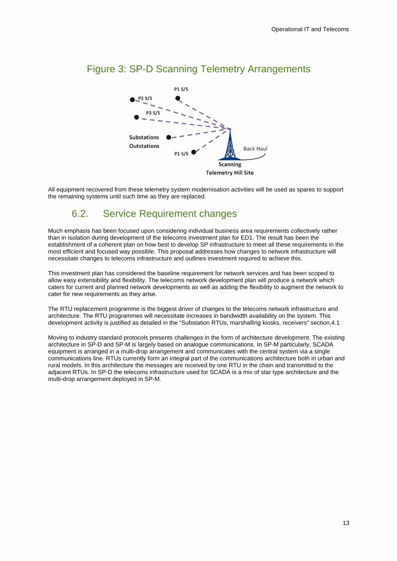
Figure 3: SP-D Scanning Telemetry Arrangements
All equipment recovered from these telemetry system modernisation activities will be used as spares to support the remaining systems until such time as they are replaced.
6.2. Service Requirement changes Much emphasis has been focused upon considering individual business area requirements collectively rather than in isolation during development of the telecoms investment plan for ED1. The result has been the establishment of a coherent plan on how best to develop SP infrastructure to meet all these requirements in the most efficient and focused way possible. This proposal addresses how changes to network infrastructure will necessitate changes to telecoms infrastructure and outlines investment required to achieve this.
This investment plan has considered the baseline requirement for network services and has been scoped to allow easy extensibility and flexibility. The telecoms network development plan will produce a network which caters for current and planned network developments as well as adding the flexibility to augment the network to cater for new requirements as they arise.
The RTU replacement programme is the biggest driver of changes to the telecoms network infrastructure and architecture. The RTU programmes will necessitate increases in bandwidth availability on the system. This development activity is justified as detailed in the “Substation RTUs, marshalling kiosks, receivers” section,4.1.
Moving to industry standard protocols presents challenges in the form of architecture development. The existing architecture in SP-D and SP-M is largely based on analogue communications. In SP-M particularly, SCADA equipment is arranged in a multi-drop arrangement and communicates with the central system via a single communications line. RTUs currently form an integral part of the communications architecture both in urban and rural models. In this architecture the messages are received by one RTU in the chain and transmitted to the adjacent RTUs. In SP-D the telecoms infrastructure used for SCADA is a mix of star type architecture and the multi-drop arrangement deployed in SP-M.
13

Operational IT and Telecoms
Figure 4: RTU Multi-drop arrangement showing RTU’s communication processing role
This system can function in this way as all RTUs use the same legacy protocols. The system, particularly in SPM will require major alteration prior to the rollout of the RTU replacement system as communications associated with different protocols need to be transmitted on the same strings.
SP’s approach to this challenge is to utilise existing bearer (such as pilot cables, fibre, microwave, radio) provisions to their maximum capability by installing active equipment which enables digital communications and introduces switching (and routing). This enables multiple sources of data (both legacy and new) to be transported over the same communications lines. The active equipment installed will manage connected telecoms bearers by continually monitoring them. This will enable better visibility of bearer deterioration and as a result better targeting of modernisation investment, e.g. UG copper Pilots, during ED1 as new equipment and increased service requirements uncover asset limitations.
This approach also offers a degree of future proofing as other services can be readily provisioned on the same telecoms infrastructure. This development work forms a significant portion of our overall network development strategy and will be deployed in both SP-D and SP-M.
Figure 5: Future Substation Vision - SCADA and Telecoms Aspects
IEC 61850
IED
IED
IED
IED IED IED
Future Primary Substation
Next Generation RTU
Minimal Hardwired I/O
Ethernet
IEC 60870-5-104
Ethernet Switch Other Services
Firewall
IED Logic
IED Telephony Services
Other Services
Radial/Star Connected
GPS
IEE 1588
Communications Connectivity
14

Operational IT and Telecoms
This architecture alteration will be carried out on in advance of the RTU replacement activity so that RTUs can be changed individually without impact to the overall system.
Figure 6: Telecoms Network Architecture Development which enables efficient sharing of infrastructure
The legacy arrangement of multiple strings of RTUs is vulnerable to the loss of a single communications bearer. In the worst case loss of the single bearer could result in the loss of services to 8 RTUs. The legacy SPM RTUs as a result came equipped with components which enabled use of a dial-up PSTN backup to the control centre. Such functionality is not available in new generation RTUs and is not supported for IEC protocols in the central system.
These PSTN backups will be removed and the telecoms network will be developed, where possible to form with Ethernet rings between Grid substations at the end of interconnected feeders, allowing RTU traffic can be provisioned both ways around the ring. This investment in communications strengthening is required to ensure that loss of any communications bearers causes minimal loss of RTU communications and other operational services.
Overall the data transported across the telecoms network is likely to increase significantly over the ED1 period in both SP-D and SP-M due to planned initiatives and foreseeable developments, therefore investment in the top level infrastructure will also be required. In SP-M this investment will take the form of expansion of the core SDH infrastructure to 20 additional Grid sites and development of existing telecoms infrastructure in sites where RTS FEPs (Front End Processors) are moved to key nodes on the telecoms network; this development is to avoid unnecessary major reinforcement of bearers on the core telecoms ring. IP services for SCADA, IP Telephony and other users will be provisioned at all G.S.Ps. Existing MUXs will get upgrades so that they can handle additional data transport requirements. In both SP-D and SP-M new communications routes will be established to strengthen the telecoms network and to ensure that there is adequate capacity to meet the demands of applications service requirements during the ED1 period.
In addition to the largely SCADA driven service investment, investment will be made mainly in SPD and to a more limited extent in SPM to provision Protection Intertripping Services as a replacement method of fault clearance as fault throwers are removed. Investment drivers for fault throwers removal are detailed in Annex C6 – Protective Equipment and Supporting Systems Strategy – SPEN, Section 6.1.
15
Operational IT and Telecoms
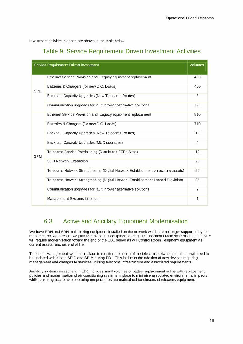
Investment activities planned are shown in the table below
Table 9: Service Requirement Driven Investment Activities
Service Requirement Driven Investment Volumes
SPD
Ethernet Service Provision and Legacy equipment replacement 400
Batteries & Chargers (for new D.C. Loads) 400
Backhaul Capacity Upgrades (New Telecoms Routes) 8
Communication upgrades for fault thrower alternative solutions 30
SPM
Ethernet Service Provision and Legacy equipment replacement 810
Batteries & Chargers (for new D.C. Loads) 710
Backhaul Capacity Upgrades (New Telecoms Routes) 12
Backhaul Capacity Upgrades (MUX upgrades) 4
Telecoms Service Provisioning (Distributed FEPs Sites) 12
SDH Network Expansion 20
Telecoms Network Strengthening (Digital Network Establishment on existing assets) 50
Telecoms Network Strengthening (Digital Network Establishment Leased Provision) 35
Communication upgrades for fault thrower alternative solutions 2
Management Systems Licenses 1
6.3. Active and Ancillary Equipment Modernisation We have PDH and SDH multiplexing equipment installed on the network which are no longer supported by the manufacturer. As a result, we plan to replace this equipment during ED1. Backhaul radio systems in use in SPM will require modernisation toward the end of the ED1 period as will Control Room Telephony equipment as current assets reaches end of life.
Telecoms Management systems in place to monitor the health of the telecoms network in real time will need to be updated within both SP-D and SP-M during ED1. This is due to the addition of new devices requiring management and changes to services utilising telecoms infrastructure and associated requirements.
Ancillary systems investment in ED1 includes small volumes of battery replacement in line with replacement policies and modernisation of air conditioning systems in place to minimise associated environmental impacts whilst ensuring acceptable operating temperatures are maintained for clusters of telecoms equipment.
16

Operational IT and Telecoms
Telecoms Active and Ancillary Equipment Modernisation activities planned for ED1 are shown in the table below.
Table 10: Active and Ancillary Equipment Activities
Active and Ancillary Equipment Modernisation Volumes
SPD
PDH Rack Modernisation 60
Management Systems Upgrades 5
Batteries Replacement 64
Air Condition Units 8
SPM
PDH Rack Modernisation 182
Control Room Telephony Platforms 2
Backhaul Radio Modernisation 4
Management Systems Upgrades 5
SDH Modernisation works 5
Batteries Replacement 128
Air Condition Units 12
7. Smart Grid Enablers The core focus of the Operational IT and Telecoms business plan is to address business as usual challenges and our investment proposal reflects this. Our planned investment in this area also offers opportunities to help enable the Smart Grid transition and is aligned to our Smart Grid strategy (Annex 7 – Smart Grid Strategy – Creating a Network for the Future – SPEN, Section 7.2). Accordingly we have established overall Design Aims and Core Objectives for all investment in this area so that it the investment is targeted in way which enables both efficient Asset Management and Smart Grid development. Our strategy is to lay foundations for each of the smart grid key building blocks; visibility, controllability and intelligence through business as usual investment in a way where incremental development is possible and systems are sustainably managed as part of core infrastructure.
17

Operational IT and Telecoms
18
Operational IT and Telecoms
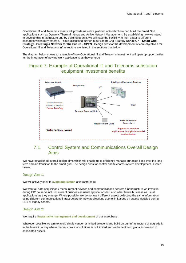
Operational IT and Telecoms assets will provide us with a platform onto which we can build the Smart Grid applications such as Dynamic Thermal ratings and Active Network Management. By establishing how we intend to develop this infrastructure and by building upon it, we will have the flexibility to then adapt to different scenarios which may emerge. This is discussed further in our Smart Grid Strategy Annex C7 – Smart Grid Strategy - Creating a Network for the Future – SPEN. Design aims for the development of core objectives for Operational IT and Telecoms infrastructure are listed in the sections that follow.
The diagram below shows an example of how Operational IT and Telecoms investment will open up opportunities for the integration of new network applications as they emerge
Figure 7: Example of Operational IT and Telecoms substation equipment investment benefits
7.1. Control System and Communications Overall Design Aims
We have established overall design aims which will enable us to efficiently manage our asset base over the long term and aid transition to the smart grid. The design aims for control and telecoms system development is listed below;
Design Aim 1:
We will actively seek to avoid duplication of infrastructure
We want all data acquisition / measurement devices and communications bearers / infrastructure we invest in during ED1 to serve not just current business as usual applications but also other future business as usual applications as they emerge. Where possible, we do not want different assets collecting the same information using different communications infrastructure for new applications due to limitations on assets installed during ED1 or legacy assets.
Design Aim 2:
We require Sustainable management and development of our asset base
Wherever possible we aim to avoid single vendor or limited solutions and build on our infrastructure or upgrade it in the future in a way where market choice of solutions is not limited and we benefit from global innovation in associated assets.
19
Operational IT and Telecoms
Design Aim 3:
We require Standardisation and Supportability for our asset base
Wherever possible, we require new control hardware and applications to be integrated and managed as part of core infrastructure. This requires Interoperability of control devices from a wide range of vendors.
7.2. Control System and Communications Development Core Objectives
Objective 1:
Develop Central System so it can be readily augmented with new functionality in a modular way in line with need
Investment in Central system hardware and software will be made in ED1 in order to keep it as current as possible. In this way the integration of new operational functionality will not be impeded by limitations in the central control systems.
Objective 2:
Build an asset base of RTUs which are addressable from each other and the control centre
This will be advanced in ED1 by buying and installing RTUs which operated with common industry standard protocols and establishing managed Ethernet services at all associated sites. This will enable the deployment of distributed control applications over multiple network sites.
Objective 3:
Readily support the integration of new substations applications
As part of the wider ED1 strategy, new protection and control substation devices will communicate with RTUs using common industry standards for substation automation. Consistent data models and protocol for communication enable standardisation and open up the ability to efficiently integrate new applications and the ability for data to be shared between substation applications.
20