open access early-life permanent deformation ... · early-life permanent deformation...
TRANSCRIPT
The Open Transportation Journal, 2009, 3, 63-69 63
1874-4478/09 2009 Bentham Open
Open Access
Early-Life Permanent Deformation Characteristics of High-Strength Subgrade Full-Scale Test Pavements
Kasthurirangan Gopalakrishnan*
Department of Civil, Construction and Environmental Engineering, Iowa State University, Ames, IA 50014, USA
Abstract: The National Airport Pavement Test Facility (NAPTF) is a state-of-the-art full-scale test facility operated by
the U.S. Federal Aviation Administration (FAA). The NAPTF is located at the William J. Hughes Technical Center near
Atlantic City, New Jersey and it provides high quality, accelerated test data from rigid and flexible pavements subjected to
simulated aircraft traffic. During the first construction cycle, the fully enclosed instrumented test track consisted of three
91.4-m (300-ft) long pavement sections with different subgrade strengths (low, medium, and high). Each subgrade had
two flexible test items and one rigid test item constructed on it. Two gear configurations, a six-wheel tridem landing gear
(Boeing 777) in one lane and a four-wheel dual-tandem landing gear (Boeing 747) in the other lane were tested
simultaneously. Transverse surface profile (TSP) measurements were made at regular intervals to monitor pavement
rutting performance. Previous research focused on analyzing the extensive data available for the low-strength and
medium-strength flexible test sections. In this study, the early-life permanent deformation characteristics of high-strength
flexible test sections were studied using the initial rutting data acquired at the NAPTF. The Power model and the Rutting
Rate model were used to characterize the rutting trends. Based on the study findings, it may be concluded that both the
Boeing 777 and Boeing 747 gear trafficking at 20.4-ton (45-kip) wheel load magnitude will not impose severe stresses on
airfield flexible pavements with high-strength subgrade even with minimal asphalt concrete surface and base layer
thicknesses. More full-scale test data are needed to verify the findings.
Keywords: NAPTF, New generation aircraft (NGA), High-strength subgrade, Airport flexible pavement, Rutting performance, power model.
INTRODUCTION
The National Airport Pavement Test Facility (NAPTF) located at the Federal Aviation Administration (FAA) William J. Hughes Technical Center, Atlantic City International Airport, New Jersey was constructed to generate full-scale testing data to support the investigation of the performance of airport pavements subjected to complex gear loading configurations of new generation aircraft (NGA) such as the Boeing 777.
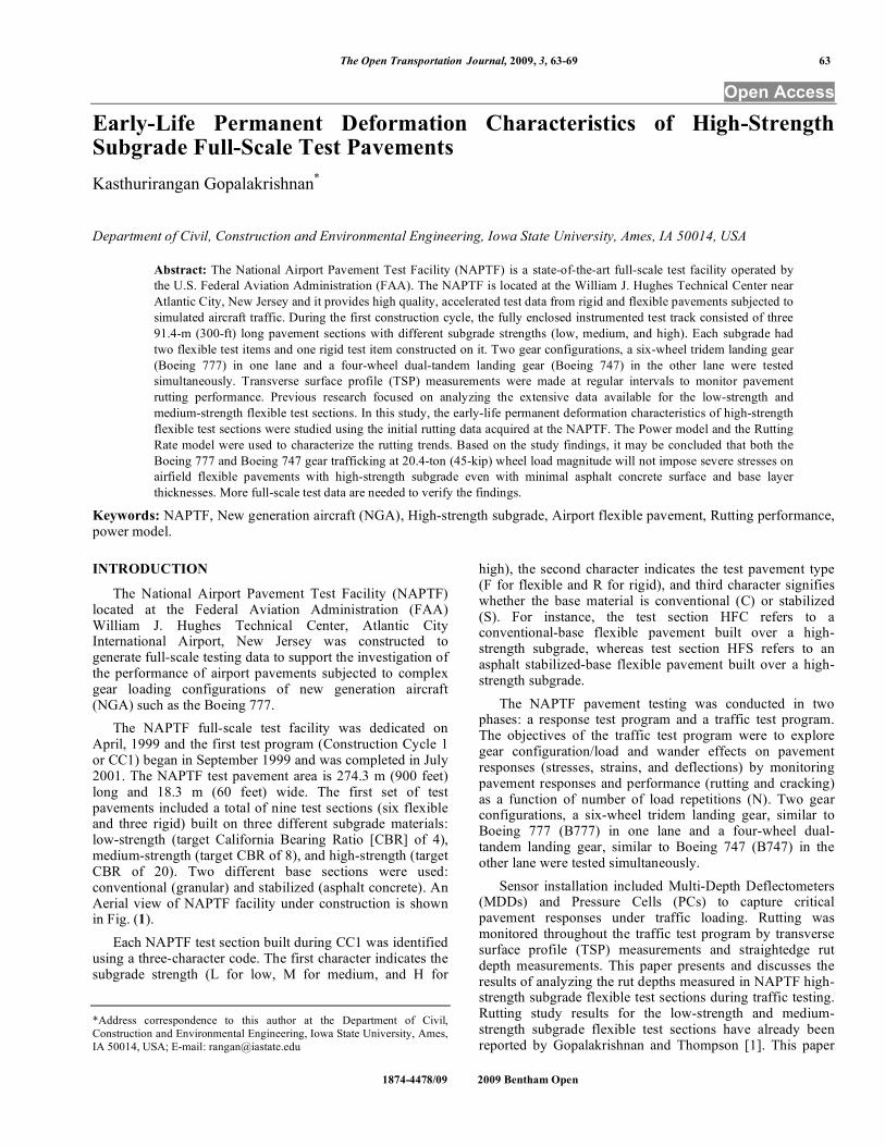
The NAPTF full-scale test facility was dedicated on April, 1999 and the first test program (Construction Cycle 1 or CC1) began in September 1999 and was completed in July 2001. The NAPTF test pavement area is 274.3 m (900 feet) long and 18.3 m (60 feet) wide. The first set of test pavements included a total of nine test sections (six flexible and three rigid) built on three different subgrade materials: low-strength (target California Bearing Ratio [CBR] of 4), medium-strength (target CBR of 8), and high-strength (target CBR of 20). Two different base sections were used: conventional (granular) and stabilized (asphalt concrete). An Aerial view of NAPTF facility under construction is shown in Fig. (1).
Each NAPTF test section built during CC1 was identified using a three-character code. The first character indicates the subgrade strength (L for low, M for medium, and H for
*Address correspondence to this author at the Department of Civil,
Construction and Environmental Engineering, Iowa State University, Ames,
IA 50014, USA; E-mail: [email protected]
high), the second character indicates the test pavement type (F for flexible and R for rigid), and third character signifies whether the base material is conventional (C) or stabilized (S). For instance, the test section HFC refers to a conventional-base flexible pavement built over a high-strength subgrade, whereas test section HFS refers to an asphalt stabilized-base flexible pavement built over a high-strength subgrade.
The NAPTF pavement testing was conducted in two phases: a response test program and a traffic test program. The objectives of the traffic test program were to explore gear configuration/load and wander effects on pavement responses (stresses, strains, and deflections) by monitoring pavement responses and performance (rutting and cracking) as a function of number of load repetitions (N). Two gear configurations, a six-wheel tridem landing gear, similar to Boeing 777 (B777) in one lane and a four-wheel dual-tandem landing gear, similar to Boeing 747 (B747) in the other lane were tested simultaneously.
Sensor installation included Multi-Depth Deflectometers (MDDs) and Pressure Cells (PCs) to capture critical pavement responses under traffic loading. Rutting was monitored throughout the traffic test program by transverse surface profile (TSP) measurements and straightedge rut depth measurements. This paper presents and discusses the results of analyzing the rut depths measured in NAPTF high-strength subgrade flexible test sections during traffic testing. Rutting study results for the low-strength and medium-strength subgrade flexible test sections have already been reported by Gopalakrishnan and Thompson [1]. This paper
64 The Open Transportation Journal, 2009, Volume 3 Kasthurirangan Gopalakrishnan
focuses on studying the rutting behavior of high-strength flexible test sections during the first few thousand passes of B777 and B747 traffic loading. All data referenced in this paper are accessible from the FAA Airport Technology website http://www.airporttech.tc.faa.gov/naptf/.
MATERIAL PROPERTIES
Both the high-strength subgrade flexible test sections (HFC and HFS) considered in this study consisted of 13 cm (5.1 in.) of Asphalt Concrete (AC) surface course. For the HFC test section, a 27-cm (10.7-in.) conventional granular base course was used whereas a 11-cm (4.5-in.) thick asphalt-stabilized base course was used for the HFS test section underneath the AC surface course. For the high-strength subgrade, the locally available sand (SW-SM soil classification – ASTM Unified Soil Classification System) was used with a target strength of 20 CBR.
The physical properties of all of the materials used in the NAPTF test items were measured before, during and after construction for three purposes: construction quality control (QC), construction acceptance, and material characterization. Tests were also conducted at the University of Illinois’ Advanced Transportation Engineering Laboratory (U of I ATREL) to characterize these materials. Tests performed on unbound aggregate layers during construction consisted of measuring in situ moisture content (ASTM D 2216), density
(ASTM D 2937), and CBR (ASTM D 4429). Dynamic Cone Penetrometer (DCP) tests were performed to characterize the variation of subgrade strength with depth and over a tight horizontal grid. Both the laboratory and field material characterization test results for NAPTF subgrade soils are presented by Gopalakrishnan and Thompson
[2].
The conventional granular base course used in HFC was composed of granular materials constructed on the finished, prepared subgrade in accordance with specifications detailed in Federal Aviation Administration (FAA) Advisory Circular (AC) 150/5370-10A “Standards for Specifying Construction of Airports” for Item P-209. Quality control (QC) testing and inspection was conducted to ensure uniformity and quality of the base material. QC for the base was based on gradation, moisture and density tests. CBR tests were not conducted as part of the QC program but were performed for material characterization. Resilient modulus tests were conducted on P-209 base material as per the Superpave Highway Research Program (SHRP) Protocol P-46 testing procedure.
The AC surface course or base course composed of mineral aggregate and bituminous material mixed in a central mixing plant and placed on a prepared course. The mixed material was spread, finished, and compacted in accordance with specifications detailed in FAA AC 150/5370-10A “Standards for Specifying Construction of
Fig. (1). Aerial view of NAPTF facility under construction (Photo Courtesy of NAPTF)
Early-Life Permanent Deformation Characteristics The Open Transportation Journal, 2009, Volume 3 65
Airports” for Item P-401. During production, aggregate gradation, binder content, mix temperature, and mixture properties, including Marshall stability, flow, void, and in-place density, were monitored. The NAPTF materials characterization test results are contained in the FAA’s materials database (accessible for download at the FAA Airport Technology website).
TRAFFIC TESTING
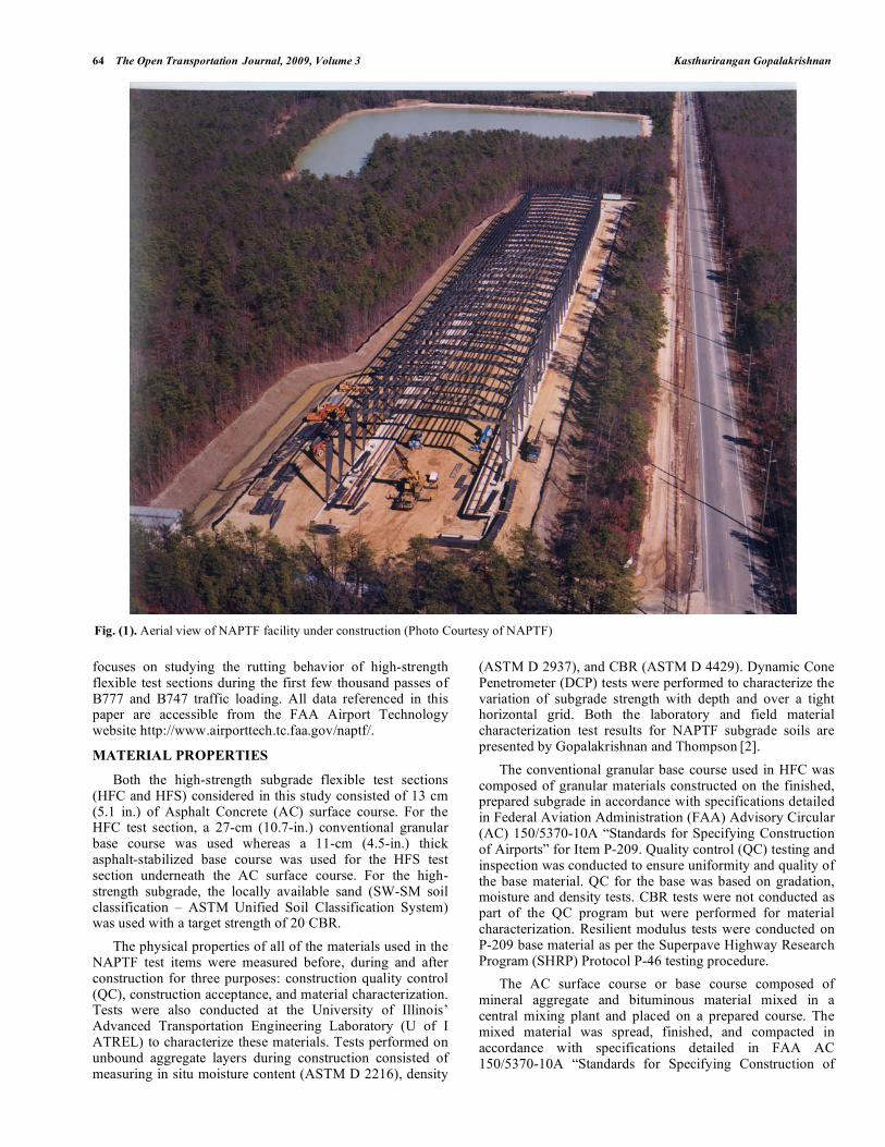
A six-wheel dual-tridem gear configuration (B777) with 1372-mm (54-inch) dual spacing and 1448-mm (57-inch) tandem spacing was loaded on the North wheel track while the South side was loaded with a four-wheel dual-tandem gear configuration (B747) having 1118-mm (44-inch) dual spacing and 1473-mm (58-inch) tandem spacing. A picture of the NAPTF traffic test machine loading both the B777 and B747 gear configuration on the test pavement is shown in Fig. (2). The wheel loads were set to 20.4 tonnes (45,000 lbs or 45 kips) each and the tire pressure was 1295 kPa (188 psi). The traffic speed was 8 km/h (5 mph) throughout the traffic test program.
To realistically simulate transverse aircraft movements, a wander pattern consisting of a fixed sequence of 66 vehicle passes (33 traveling in the East direction and 33 traveling in the West direction), arranged in nine equally spaced wander positions (or tracks) at intervals of 260 mm (10.25 inches), was used during traffic tests. This wander pattern simulates a normal distribution of aircraft traffic with a standard deviation ( ) of 775 mm (30.5 inches) that is typical of multiple gear passes in airport taxiways.
The NAPTF failure criterion, based on the criterion used by the US Corps of Engineers’ Multiple Wheel Heavy Gear Load (MWHGL) Tests, is ‘at least 25.4-mm (1-inch) surface upheaval adjacent to the traffic lane’ [3]. This upheaval
outside the traffic lane can be caused by shear in any of the structural layers including the subgrade. However, the usual intention is to have the subgrade fail first.
It is important to note that, in the 25.4-mm (1-inch) surface upheaval failure criterion, there is no limit on the maximum rut depth. Thus, a surface upheaval of 25.4 mm (1 inch) may be accompanied by a 13-mm (0.5-inch) rut depth or rut depths in excess of 50 mm (2 inches) to 75 mm (3 inches) with no limit on the maximum allowable rut depth. However, according to the Unified Facilities Criteria (UFC) [4], rut depth in excess of 25.4 mm (1 inch) is considered as ‘High’ severity rutting and it constitutes a significant functional failure requiring major maintenance activities. It is recognized that ultimately the magnitude of surface rut depths will dictate performance irrespective of surface upheaval. It is noted that both the stabilized and conventional test pavements were designed to provide equal performance. However, the traffic test results showed that the subgrade strength influenced the rutting performance significantly. Unfortunately, the traffic testing was discontinued on the high-strength subgrade test sections after the initial few thousand passes since they did not show any sign of distress.
TRANSVERSE SURFACE PROFILE MEASUREMENTS
Rutting is the load-induced permanent deformation of a flexible pavement caused by a combination of densification and shear-related deformation [5]. Rutting in paving materials develop gradually with an increasing number of load applications, usually appearing as longitudinal depressions in the wheel paths accompanied by small upheavals to the sides [6]. Permanent deformation in any or all of the pavement layers and/or subgrade under repeated traffic loading contributes to the total accumulation of pavement surface rutting. Transverse surface profile (TSP)
Fig. (2). Picture of NAPTF test vehicle (Photo Courtesy of NAPTF).
B777 B747
66 The Open Transportation Journal, 2009, Volume 3 Kasthurirangan Gopalakrishnan
measurements as well as rut depth measurements using a 3.66 m- (12 foot-) long straightedge were made throughout the traffic testing.
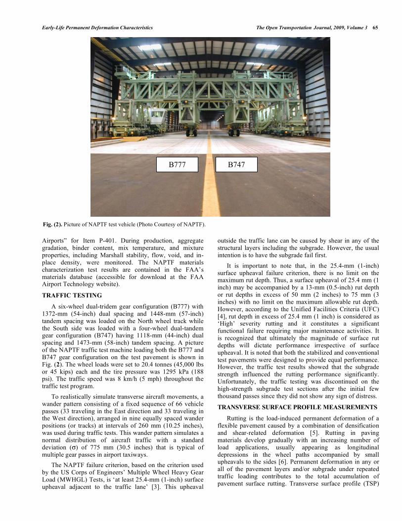
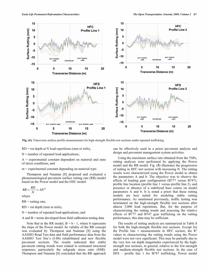
A manually propelled inertial profiling device was used to measure the transverse surface elevation profiles. A recommended test speed of 2.0-km/h (1.24-mph) was used and the profile elevation was recorded once every 250 mm (9.84 inches). In each test item, TSPs were measured along two main profile lines (Profile Line 1 and 2) marked across the pavement. In the HFC and HFS test items, these two profile lines were at the one-third points along the test items. In Fig. (3), the location of the main profile lines and the location of traffic lanes together with test gear configurations are shown. All profiles were measured in the North-to-South direction. During data processing it was ensured that the final profile extends only across the 18.3-m (60-foot) width of the test pavement.
Using the TSP measurements, for a given number of load repetitions (N), maximum surface ruts were extracted from each traffic lane. For a given TSP, the maximum surface rut depth in a traffic lane was defined as the minimum profile elevation occurring within the width of that traffic lane (9.1 m [30 ft.]).
The TSPs measured along profile lines 1 and 2 at specific number of load repetitions (N) are plotted in Fig. (4) for both the high-strength subgrade flexible test sections. It appears that the TSP measurements in B747 traffic lane of ‘HFS – Profile Line 1’ are in error and therefore they will be omitted from the rest of the analysis. One of the specific objectives of NAPTF traffic testing program was to assess the level of pavement damage expected from the six-wheel landing gear on the B777 airplane relative to the dual and dual-tandem landing gears used on aircraft, such as the B747, in the remainder of the fleet. The TSP measurements indicate that the magnitude of rut depths under B777 and B747 trafficking are not significantly different at least for the first few thousand passes.
RUTTING ANALYSIS
A number of analytically-based, statistically-based, mechanistic, or mechanistic-empirical, and
phenomenological models have been proposed to predict permanent deformation in asphalt concrete, granular materials, and soils. The NCHRP 1-26 study considered several material permanent strain accumulation models and pavement system rutting models and concluded that the predominant flexible pavement rutting model is the log permanent strain-log load repetitions phenomenological model, also known as the Power model [7]. Thompson and Nauman [8] noted that the Power model was applicable to all conventional flexible paving materials (asphalt concrete and granular materials) and subgrade soils and it was concluded that flexible pavement surface rutting (an accumulation of permanent deformation from all of the paving layers and subgrade) can be characterized by a phenomenological model of the same form expressed as follows:
log RD = a + b logN
or
RD = ANb
(1)
where
RD = rut depth (mm or mils),
a and b = experimentally determined factors, and
A = antilog of a.
The NCHRP 1-26 study indicated that for reasonable stress states (considerably below material failure strengths), the ‘b’ term in the model is generally in the range of 0.1 to 0.2 [7]. The ‘A’ term is quite variable and is strongly influenced by material/soil type, repeated stress state, and factors influencing material shear strength [8].
Another popular permanent strain accumulation prediction model is the Ohio State University (OSU) model [9] included in a pavement design system developed for the Ohio Department of Transportation. The model (in terms of surface rutting) is:
RD
N= ANm
where
N
9.1 m
3.9 m
0 m
-3.9 m
-9.1 m
B747
B777
C/L
PR
OF
IL
E L
IN
E 1
PR
OF
IL
E L
IN
E 2
N
9.1 m
3.9 m
0 m
-3.9 m
-9.1 m
B747B747
B777B777
C/L
PR
OF
IL
E L
IN
E 1
PR
OF
IL
E L
IN
E 2
Fig. (3). NAPTF traffic test lanes and transverse surface profile measurement locations (profile lines 1 and 2).
Early-Life Permanent Deformation Characteristics The Open Transportation Journal, 2009, Volume 3 67
RD = rut depth at N load repetitions (mm or mils),
N = number of repeated load applications,
A = experimental constant dependent on material and state of stress conditions, and
m = experimental constant depending on material type.
Thompson and Nauman [8] proposed and evaluated a phenomenological pavement surface rutting rate (RR) model based on the Power model and the OSU model:
RR =RD
N= ANB
where
RR = rutting rate,
RD = rut depth (mm or mils),
N = number of repeated load applications, and
A and B = terms developed from field calibration testing data
Note that in the RR model, B = b - 1, where b represents the slope of the Power model. he validity of the RR concept was evaluated by Thompson and Nauman [8] using the AASHO Road Test data and field performance data from the AASHO Test Site’s (I-80) rehabilitated and new flexible pavement sections. The results indicated that stable pavement rutting trends were related to estimated structural responses, particularly the subgrade stress ratio (SSR). Thompson and Nauman [8] concluded that the RR approach
can be effectively used in a priori pavement analysis and design and pavement management system activities.
Using the maximum surface ruts obtained from the TSPs, rutting analyses were performed by applying the Power model and the RR model. Fig. (5) illustrates the progression of rutting in HFC test section with increasing N. The rutting results were characterized using the Power model to obtain the parameters A and b. The objective was to observe the effects of loading gear configuration (B777 versus B747), profile line location (profile line 1 versus profile line 2), and presence or absence of a stabilized base course on model parameters A and b. It is noted a priori that these rutting models are best suited for modeling stable rutting performance. As mentioned previously, traffic testing was terminated on the high-strength flexible test sections after almost 3,000 load repetitions. But, for the purpose of characterizing the rutting trends and assessing the relative effects of B777 and B747 gear trafficking on the rutting performance, this data may be sufficient.
The results of rutting analysis are summarized in Table 1 for both the high-strength flexible test sections. Except for the Profile line 1 measurements in HFC section, the R
2
values in characterizing the rutting trends using the Power model were not very significant. This may be partially due to the very low rut depth magnitudes experienced by the high-strength test sections, in general, relative to the low-strength and medium-strength flexible test sections. In the case of HFS – profile line 1 for B747 trafficking, Power model
-15
-10
-5
0
5
10
15
0 5 10 15 20
Transverse Distance (m)
Su
rfa
ce
Ru
ttin
g (
mm
)
B777 TRAFFIC
LANE
B747 TRAFFIC
LANECENTERLINE
HFC
Profile Line 1
-15
-10
-5
0
5
10
15
0 5 10 15 20
Transverse Distance (m)
Su
rfa
ce
Ru
ttin
g (
mm
)
B777 TRAFFIC
LANE
B747 TRAFFIC
LANECENTERLINE
HFC
Profile Line 2
-15
-10
-5
0
5
10
15
0 5 10 15 20
Transverse Distance (m)
Su
rfa
ce
Ru
ttin
g (
mm
)
B777 TRAFFIC LANE B747 TRAFFIC LANE
CENTERLINE
HFS
Profile Line 1
-15
-10
-5
0
5
10
15
0 5 10 15 20
Transverse Distance (m)
Su
rfa
ce
Ru
ttin
g (
mm
)B777 TRAFFIC
LANE
B747 TRAFFIC
LANECENTERLINE
HFS
Profile Line 2
Fig. (4). Transverse surface profile measurements for high-strength flexible test sections under repeated trafficking.
68 The Open Transportation Journal, 2009, Volume 3 Kasthurirangan Gopalakrishnan
yielded very poor fit and therefore the results are not reported. In the Power model, b represents the rate of rutting while A is representative of the overall pavement rutting potential under specified traffic loading. In general, the rate of rutting is similar for all test cases except for HFC section subjected to B747 trafficking.
0.0
1.0
2.0
3.0
4.0
5.0
6.0
7.0
8.0
9.0
10.0
0 1000 2000 3000 4000Number of Load Repetitions (N)
Ru
t D
ep
th (
mm
)
B777
B747
HFC
Profile Line 1
Fig. (5). Rut depth versus N.
According to the Unified Facilities Criteria (UFC), rut depth in excess of 25.4 mm (1 in.) is considered as ‘High’
severity rutting and it constitutes a significant functional failure requiring major maintenance activities. Based on the Power model rutting characterization results, in order to reach a rut depth of 25.4 mm (1 in.), it would take at least 10
10 repetitions of B777 and B747 gear trafficking at 20.4-
ton (45-kip) wheel load for both the high-strength test sections.
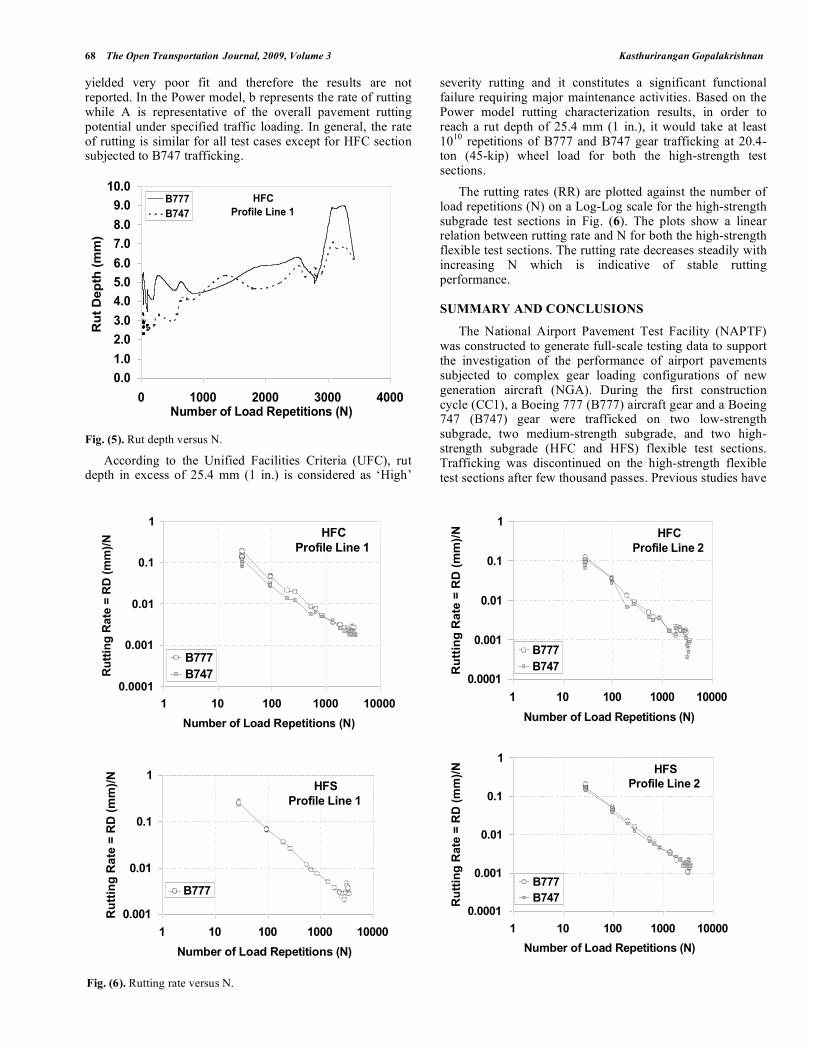
The rutting rates (RR) are plotted against the number of load repetitions (N) on a Log-Log scale for the high-strength subgrade test sections in Fig. (6). The plots show a linear relation between rutting rate and N for both the high-strength flexible test sections. The rutting rate decreases steadily with increasing N which is indicative of stable rutting performance.
SUMMARY AND CONCLUSIONS
The National Airport Pavement Test Facility (NAPTF) was constructed to generate full-scale testing data to support the investigation of the performance of airport pavements subjected to complex gear loading configurations of new generation aircraft (NGA). During the first construction cycle (CC1), a Boeing 777 (B777) aircraft gear and a Boeing 747 (B747) gear were trafficked on two low-strength subgrade, two medium-strength subgrade, and two high-strength subgrade (HFC and HFS) flexible test sections. Trafficking was discontinued on the high-strength flexible test sections after few thousand passes. Previous studies have
0.0001
0.001
0.01
0.1
1
1 10 100 1000 10000
Number of Load Repetitions (N)
Ru
ttin
g R
ate
= R
D (
mm
)/N
B777
B747
HFC
Profile Line 1
0.0001
0.001
0.01
0.1
1
1 10 100 1000 10000
Number of Load Repetitions (N)
Ru
ttin
g R
ate
= R
D (
mm
)/N
B777
B747
HFC
Profile Line 2
0.001
0.01
0.1
1
1 10 100 1000 10000
Number of Load Repetitions (N)
Ru
ttin
g R
ate
= R
D (
mm
)/N
B777
HFS
Profile Line 1
0.0001
0.001
0.01
0.1
1
1 10 100 1000 10000
Number of Load Repetitions (N)
Ru
ttin
g R
ate
= R
D (
mm
)/N
B777
B747
HFS
Profile Line 2
Fig. (6). Rutting rate versus N.

Early-Life Permanent Deformation Characteristics The Open Transportation Journal, 2009, Volume 3 69
focused on analyzing the extensive response and performance data available for low-strength and medium-strength flexible test sections.
Table 1. Summary of Power Model (Rut Depth = ANb)
Rutting Parameters
Traffic
Gear
Test
Section
Profile
Line A b R
2
1 2.936 0.094 0.459 HFC
2 2.398 0.049 0.198
1 5.374 0.050 0.157
B777
HFS 2 - - -
1 1.402 0.174 0.831 HFC
2 1.541 0.103 0.341
1 - - - B747
HFS 2 3.472 0.039 0.206
In this paper, the early-life permanent deformation characteristics of high-strength flexible test sections were studied using the initial rutting data acquired at the NAPTF. The Power model and the Rutting Rate model were used to characterize the rutting trends from the high-strength test sections as these models were found to be suitable in analyzing rutting data from low-strength and medium-strength test sections. However, considering the relatively smaller rut depth magnitudes experienced by the high-strength test sections and the type of material used in the subgrade (locally available sand), these models may not be fully valid in characterizing the rutting behavior of high-strength subgrade test sections.
One of the specific objectives of NAPTF traffic testing program was to assess the level of pavement damage expected from the six-wheel landing gear on the B777 airplane relative to B747 airplane. Previous studies reported that both the B777 and B747 trafficking had almost similar impact on the low-strength medium-strength flexible test sections in terms of rutting performance. Based on this study, the TSP measurements indicate that the magnitude of rut depths under B777 and B747 trafficking are not significantly different at least for the first few thousand passes in both the high-strength flexible test sections.
Except for the Profile line 1 measurements in HFC section, the R
2 values in characterizing the rutting trends
using the Power model were not very significant. This may be partially due to the very low rut depth magnitudes experienced by the high-strength test sections, in general, relative to the low-strength and medium-strength flexible test sections. In general, the rate of rutting is similar for all test cases except for HFC section subjected to B747 trafficking. Based on the Power model rutting characterization results, in
order to reach a rut depth of 25.4 mm (1 in.), it would take at least 10
10 repetitions of B777 and B747 gear trafficking at
20.4-ton (45-kip) wheel load for both the high-strength test sections. The rutting rate decreased steadily with increasing N for the high-strength flexible test sections which is indicative of stable rutting performance. From these results, it can be concluded that both the B777 and B747 gear trafficking at 20.4-ton (45-kip) wheel load magnitude will not impose severe stresses on airfield flexible pavements with high-strength subgrade even with minimal asphalt concrete surface and base layer thicknesses. More full-scale test data are needed to verify these findings.
ACKNOWLEDGEMENTS/DISCLAIMER
The author gratefully acknowledges the assistance provided by Prof. Marshall R. Thompson at the University of Illinois at Urbana-Champaign in conducting this study. Special thanks to Dr. David Brill, Dr. Gordon Hayhoe, and Dr. Navneet Garg of FAA for their help. The author also gratefully acknowledges the NAPTF for giving permission to use Figs. (1, 2) included in this paper. The contents of this paper reflect the views of the author who is responsible for the facts and accuracy of the data presented within. The contents do not necessarily reflect the official views and policies of the FAA. This paper does not constitute a standard, specification, or regulation.
REFERENCES
[1] K. Gopalakrishnan and M.R. Thompson, “Severity effects of dual-tandem and dual-tridem repeated heavier aircraft gear loading on
pavement rutting performance”, Int. J. Pavement. Eng., vol. 7, no. 3, pp. 179-190, 2006.
[2] K. Gopalakrishnan and M.R. Thompson, “Characterization of NAPTF subgrade soils for mechanistic-based analysis and design
of airport flexible pavements”, Int. J. Pavement. Eng., vol. 8, no. 4, pp. 307-321, 2007.
[3] R.G. Ahlvin, “Origin of developments for structural design of pavements”, Technical Report GL-91-26, Waterways Experiment
Station, US Army Corps of Engineers, Vicksburg, MS, USA, 1991. [4] US COE, “O&M: PAVER, Asphalt surfaced airfields pavement
condition index (PCI)”, UFC Manual 3-270-06, U.S. Army Corps of Engineers (Preparing Activity), 2001.
[5] T.D. White, J.E. Haddock, A.J. Hand, and H. Fang, “Contributions of pavement structural layers to rutting of hot mix asphalt
pavements”, National Cooperative Highway Research Program Report 468, Transportation Research Board, National Research
Council, Washington, D.C., 2002. [6] J.B. Sousa, J. Craus, and C.L. Monismith, “Summary report on
permanent deformation in asphalt concrete”, Strategic Highway Research Program Report SHRP-A/IR-91-104, National Research
Council, Washington, D.C., 1991. [7] NCHRP. “Calibrated mechanistic structural analysis procedures for
pavements”, Final Report, Volume II-Appendices. National Cooperative Highway Research Program Project 1-26, TRB,
National Research Council, Washington, D.C., 1990. [8] M. R. Thompson and D. Nauman, “Rutting rate analysis of the
AASHO road test flexible pavements”, Transp. Res. Record, vol. 1384, pp. 36-48, 1993.
[9] K. Majidzadeh, M. Aly, F. Bayomy, and A. El-Laithy, “implementation of a pavement design system: volumes 1 & 2”,
Research Project EES 579, Ohio State University, Columbus, Ohio, 1981.
Received: October 24, 2008 Revised: February 3, 2009 Accepted: February 9, 2009
© Kasthurirangan Gopalakrishnan; Licensee Bentham Open.
This is an open access article licensed under the terms of the Creative Commons Attribution Non-Commercial License (http://creativecommons.org/licenses/by-
nc/3.0/) which permits unrestricted, non-commercial use, distribution and reproduction in any medium, provided the work is properly cited.