elimination of permanent deformation of travelling cranes ... · elimination of permanent...
TRANSCRIPT

A R C H I V E S o f
F O U N D R Y E N G I N E E R I N G
Published quarterly as the organ of the Foundry Commission of the Polish Academy of Sciences
ISSN (1897-3310)Volume 8
Issue 2/2008
149 – 154
33/2
A R C H I V E S o f F O U N D R Y E N G I N E E R I N G V o l u m e 8 , I s s u e 2 / 2 0 0 8 , 1 4 9 - 1 5 4 149
Elimination of permanent deformation
of travelling cranes box girders operating in foundry shops
St. Wolny*, St. Dzik**
Department of Strength of Materials, AGH University of Science and Technology al. Mickiewicza 30 Kraków Poland
Corresponding author. E-mail address: *[email protected], **[email protected]
Received 08.02.2008; accepted in revised form 29.02.2008
Abstract The serious problem in travelling cranes maintenance, crane supporting beams and other carrying elements of material handling
facilities in foundry shops is phenomenon of permanent deformations. There are known many ways to eliminate these deformations like mechanical compression by tension members however a disadvantage of such methods is work consuming process of railways rectification. One of technological methods relies on application of shrinkage of compression plates welded with box girder. Regeneration with the use of such method can be executed for the travelling cranes box girders but also with travelling crane support beams that have permanent deformations in both vertical or horizontal planes. In this paper different variants of such process execution are presented, depending on the kind and dimension of the permanent deformation. Keywords: Foundary material haundling; Traveling crane; Box girdes; Elimination of permament deformation; Technical compression.
1. Introduction When monitoring the behaviour of such supporting structures
as crane beams or travelling crane girders, one can notice that after some period of operation permanent deflections of these elements occur. There are several reasons for this phenomenon e.g. inappropriate operation of machines, welding the rails onto the upper beam flanges or overhead cranes girders, the lack of pre-deflection, etc. This problem was the subject-matter of the papers [1, 2, 3] where the authors attempted to determine the reasons for the permanent deflections of the traveling crane girders that operated a foundary shop.
Figure 1 presents graphs that show the increasing permanent deflection of the carrying girders on the engine side and on the side of the power supply in the case of the grab-magnet and
magnet travelling cranes. These are the deflections measured in the vertical piane. Some travelling cranes in operation have deflections in the horizontal plane which is illustrated by the graph of the rectilinearity measurements of the rails and girders that was made following the geodesic measurements at a travelling crane with a span of 25 m (fig.2).
The main cause of the creation of permanent deflections of the welded travelling crane girders is the relaxation of the internal stresses that are caused by the welding shrinkage which occurs in the course of constructing the crane. This is proved by the fact that lattice girders, which require significantly fewer welding operations than plate or box girders, show a lesser permanent deflection when compared to box girders. This phenomenon does not occur in the girders constructed from I — bars with a screwed down running rail [1].

Fig. 1. Diagram of the deflection growth in two travelling cranes
Fig. 2. Linearity of the rails and girders of the travelling crane in a
Polish foundary The reasons of the permanent deflection growth have not been fully detected yet since several factors are to be blamed [1]. According to statistic investigations the reasons may be as follows: • relaxation of the internal stresses (especially in the initial
stage of operation) • maintenance operations that require welding (in the course of
the exchange of the rails welded to the upper spar flange), • loading the travelling crane over its standard rating. There are several methods of restoring the primary shape of the durably deflected carrying There are several methods of restoring the primary shape of the durably deflected carrying girders [4]. The paper presents one of the ways of eliminating the permanent deflections i.e. technological compression. There are ways of eliminating them with mechanical methods by compressing the lower spar flange by a system of steel tension members but a complex joint where tension members are anchored is a drawback.
2. The nature and theoretical basis of the technological compression
In order to eliminate the permanent deflections the phenomenon of the welding shrinkage was used that occurs after the welding of side cover plates or a bottom cover plate to a strained girder. The bottom cover plate welded to the bottom flange by means of two welds is presented in fig.3. The placing of the weld is accompanied by a strong and concentrated heat source of the electric arc which results in a local warming of the girder. The thermal deformations of the heated part are limited by the surrounding material that has not been heated to such a high degree or not heated at all. It can be concluded from the practical experience presented in paper [5] that in the course of welding of a thin sheet, when the electrode is shifted rapidly along the sheet the heat exchange does not occur between the adjacent sections.
Fillet weld
Fig. 3. Model of a box girder with a bottom cover plate welded on The isotherms run parallelly to the direction of welding, which indicates that the heat propagates perpendicularly to the direction of welding. One can differentiate three thermal states in the course of this process: State 1 – The cover plate sheet is heated to the temperature T < T . In this temperature range the tensile stresses in the plate are in the elastic range and the deflection convexity increases downwards together with the temperature growth.
p
State 2 - The heating temperature reaches the value T = T , the tensile stresses reach the yield point R and the deflection has its maximum value. A further increase of the temperature does not result in the increase of the deflection but in its decrease (R decreases) which compresses the cover plate. (When the temperature T = 600° C the yield point R and Young's modulus E are close to zero). The shape and dimensions of the cover plate return to their initial state, which results in the straightening of the girder.
p
et
et
et
t
State 3 - A gradual lowering of the temperature T = T results in the expanding of the element, and when the ambient temperature is reached the cover plate sheet is compressed (its length is shorter than the initial one) and the girder's convexity is directed upwards.
p
where:Tp - the temperature when the compressive stresses in the cover plate reach the yield point Ret , Ret - the yield point, Et - Young's modulus.
A R C H I V E S o f F O U N D R Y E N G I N E E R I N G V o l u m e 8 , I s s u e 2 / 2 0 0 8 , 1 4 9 - 1 5 4 150

The deflection levelling of box girders with a plastic strain is carried out by placing the weld with an appropriate thickness and distance from the gravity centre of the girder's cross-section in question. In order to determine the deflection of the girder that is caused by placing a weld or welds, the formula suggested by M.Myśliwiec [5] may be applied, which in the case of simple-supported beams with the span L has the shape:
[cmI
yLqfx
śr
1
21
8μ
= ] (1)
where:
μ - coefficient dependent on the welding parameters, μ = -3,53 ·106 [cm3/cal],
q1 - linear energy of placing the fillet weld q1 = 14 000 a2 [cal/cm], yśr - average distance of the welds from the gravity
centre of the section [cm], Ix1 - moment of inertia of the girder's section with the
consideration of the cover plates [cm4], L - span of the girder [cm].
The methods of restoring the initial shape of the girders or crane beams that have horizontal and vertical plastic strains which appeared in the course of the operation of the travelling cranes or rails and which are made as welded elements are presented below. Box girders of travelling cranes or crane beams whose plastic strain may have the shape as in fig.4. will be the subject of further analysis.
Fig. 4. Simple cases of box girder’s strains a) without strain, b) with vertical strain c) vertical and bottom lateral strain d) vertical and upper lateral strain e) vertical and both lateral strain f) vertical and equal lateral strain
3. The levelling of the vertical deflections of a girder
In most cases the box girders have plastic vertical strain of the shape b from fig.4. The levelling of the deflections can be carried out in one or two stages depending on their values. In the case of a one-stage method two side cover plates are welded on (fig.5) and when the deflections are significant the levelling should be done in two stages; in the second stage one more cover plate is welded on under the bottom spar flange. For typical box girders the length I of the cover plates is shorter than the span L. Their ratio is l/L ≅ 0.8, thus l = 0.8 L [5, 6] (2) The above dependence should be taken into consideration in the formula (1). In order to reach the levelling of the system the deflection caused by the welding of the cover plate f should equal the plastic strain yf.
Fig. 5. Cross-section of a girder with the suggested compression cover plates which enable the levelling of the vertical deflections The fulfilment of the above condition with the application of the dependence (2) enables the determination of the thickness of one of the four fillet welds which, when placed in one stage, makes it possible to restore the initial (linear) shape of the girder. The thickness can be determined from the relation:
[cmyLIy
aśr
xf21,7= ] (3)
In the case of a two-stage compression, which is started from the welding of a bottom cover plate, the thickness of one of the two fillet welds is determined from the formula:
[ ]cmyLIy
aśr
xfi
12
11 10= (4)
The remaining part of the permanent deflection is levelled in the second stage by welding the side cover plates – four additional welds whose thickness is
A R C H I V E S o f F O U N D R Y E N G I N E E R I N G V o l u m e 8 , I s s u e 2 / 2 0 0 8 , 1 4 9 - 1 5 4 151

[cmmyL
Iya
śrII
xIIfIIII
β⋅= 21,7 ] (5)
where: yfII - remaining part of the permanent deflection yfII = yf - yfl [cm], yf1 - deflection levelled in stage I [cm], lxI, lxII - moment of inertia with the consideration of the cover plates in stage I and II, respectively [cm4] yśr, yśrll - average distance of the welds from the centre of gravity in stage I and II, respectively [cm] mß - coefficient determining the influence of initial stresses, dependent on ß = Δ 0 /ε e , Δ 0 - prestrains in the point where weld is made in stage II
nqI
yyA x
śr1
1
2
10
1 μ⎟⎟⎠
⎞⎜⎜⎝
⎛+=Δ (6)
n – number of the filet welds, εe - deflection at the yield point – for constructional steel εe = 12.· 10-4. The value of the coefficient mp can be assumed as [5] : mß = 1 – ß for 0<ß<1 mß = 1 -2ß for -0,5<ß<0 (7) mß = 4ß for -0,75<ß<-0,5
4. Levelling of the permanent vertical and horizontal deflections of girders
In the case when the girder is deformed permanently in horizontal and vertical planes (fig.6a) the deflections can be eliminated with the application of two methods [6] [7] [8] [9]:
Fig. 6. The case of a girder deflection in the vertical and
horizontal planes under discussion Method I - a) elimination of a vertical deflection yf b) elimination of a horizontal deflection of the upper spar
flange xg together with the elimination of the bottom spar horizontal deflection xd. Method II - a simultaneous elimination of the horizontal deflections xg and xd and vertical deflection yf (it is suggested to be applied in the case of insignificant horizontal strains). When a two-stage method is applied, first the side cover plates are welded with welds whose thickness is given by
[ ]cmyLIy
aśr
xIy21,7=
(8) and then the upper and bottom welds are made, which eliminate the horizontal deflections
śr
xIgg yL
Ixa 210=
(9)
βmxLIx
a ydd 210
⋅= (10)
When the horizontal and vertical deflections are levelled simultaneously, the thickness of the welds and their distances from the gravity centre of the girder's cross-section should be adjusted in such a way that the assumed effect can be achieved. The geometrical quantities are shown in fig.6b. The target that was assumed is reached when the following assumption are made:
2
2
3
321
132
321
gx
yyy
gdxxx
fyyy
xf
fff
xxfff
yfff
=
−=
+=−+
=−+
(11)
Having solved the system of equations (11) and applied additionally the formula (1), the following relations are obtained:
( )21
22
1
2
1
23
23
232
221
21
1
211
2
1
02,0
01,0
2
02,02
aaI
xLx
IxaLx
yayaya
IayLfy
yd
yg
xyf
−=
=
−=
==
(12)
In the above equations al, a2, y1, y2 and y3 are the unknowns; as there are four equations, the values of y1 and y3 are determined on the basis of the geometric dimensions of the girder.
A R C H I V E S o f F O U N D R Y E N G I N E E R I N G V o l u m e 8 , I s s u e 2 / 2 0 0 8 , 1 4 9 - 1 5 4 152
[ ],221
1 cmb
yhy c −−=
[ ]cmyhy c+=23 (13)
Then the dimensions of the welds al, a2, a3 and y2 are calculated while the values and y3 are considered to be known.
2
3231
21
2
12
11
13
112
1,7
10
2
yyayaa
yLJy
a
xxI
La
hxIxyIy
xf
gy
gyfx
+=
⋅=
⋅=
+=
(14)
5. Elimination of permanent deflection in industrial facilities Discussed way of box girders permanent deflection have been on industrial scale implemented in some production plants. Industrial “rectification” has been executed in three variants: Variant I - side plates were only welded. Variant II - side and bottom plates were welded. Variant III - plates were welded after the girder was stamped on. Two-stage variant of rectification – utilized in the case of enormous permanent deformation has been performed in travelling crane operating in an ironwork plant. It was the crane of L = 28m span, and Q = 125kN lifting capacity [10] [11] [12]. Girders of that crane were permanently deflrcted by: - side girder, f = -41 mm, - drive side girder, f = -49 mm.
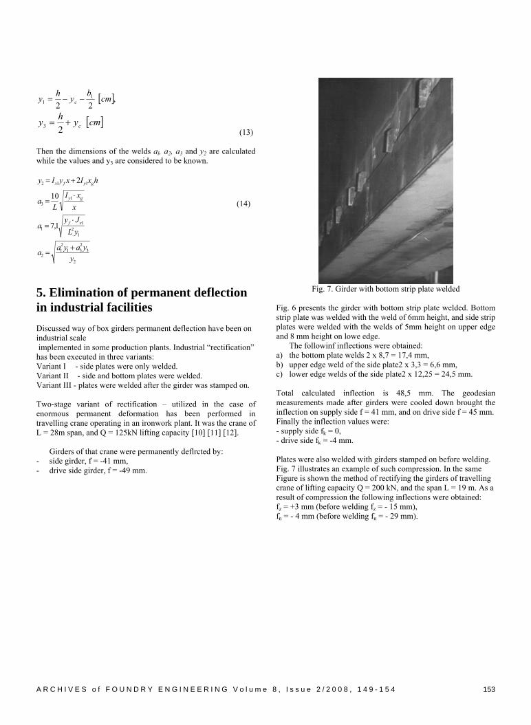
Fig. 7. Girder with bottom strip plate welded
Fig. 6 presents the girder with bottom strip plate welded. Bottom strip plate was welded with the weld of 6mm height, and side strip plates were welded with the welds of 5mm height on upper edge and 8 mm height on lowe edge. The followinf inflections were obtained: a) the bottom plate welds 2 x 8,7 = 17,4 mm, b) upper edge weld of the side plate2 x 3,3 = 6,6 mm, c) lower edge welds of the side plate2 x 12,25 = 24,5 mm. Total calculated inflection is 48,5 mm. The geodesian measurements made after girders were cooled down brought the inflection on supply side f = 41 mm, and on drive side f = 45 mm. Finally the inflection values were: - supply side fk = 0, - drive side fk = -4 mm. Plates were also welded with girders stamped on before welding. Fig. 7 illustrates an example of such compression. In the same Figure is shown the method of rectifying the girders of travelling crane of lifting capacity Q = 200 kN, and the span L = 19 m. As a result of compression the following inflections were obtained: fz = +3 mm (before welding fz = - 15 mm), fn = - 4 mm (before welding fn = - 29 mm).
A R C H I V E S o f F O U N D R Y E N G I N E E R I N G V o l u m e 8 , I s s u e 2 / 2 0 0 8 , 1 4 9 - 1 5 4 153
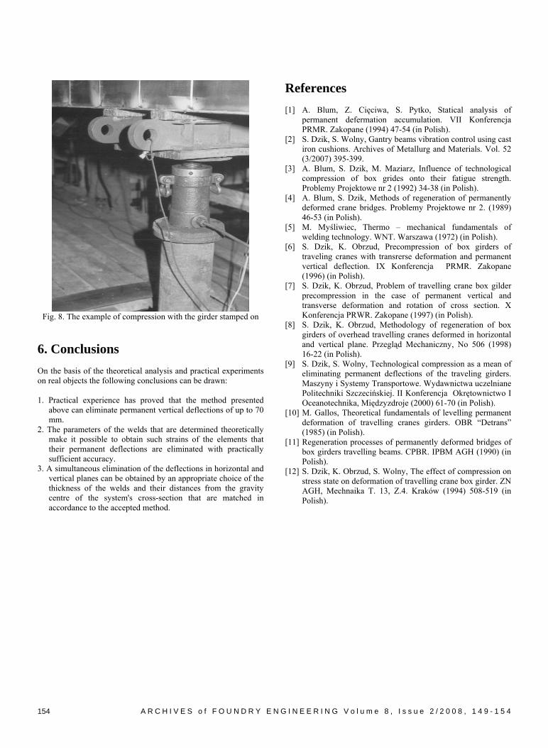
Fig. 8. The example of compression with the girder stamped on
6. Conclusions On the basis of the theoretical analysis and practical experiments on real objects the following conclusions can be drawn: 1. Practical experience has proved that the method presented
above can eliminate permanent vertical deflections of up to 70 mm.
2. The parameters of the welds that are determined theoretically make it possible to obtain such strains of the elements that their permanent deflections are eliminated with practically sufficient accuracy.
3. A simultaneous elimination of the deflections in horizontal and vertical planes can be obtained by an appropriate choice of the thickness of the welds and their distances from the gravity centre of the system's cross-section that are matched in accordance to the accepted method.
References [1] A. Blum, Z. Cięciwa, S. Pytko, Statical analysis of
permanent defermation accumulation. VII Konferencja PRMR. Zakopane (1994) 47-54 (in Polish).
[2] S. Dzik, S. Wolny, Gantry beams vibration control using cast iron cushions. Archives of Metallurg and Materials. Vol. 52 (3/2007) 395-399.
[3] A. Blum, S. Dzik, M. Maziarz, Influence of technological compression of box grides onto their fatigue strength. Problemy Projektowe nr 2 (1992) 34-38 (in Polish).
[4] A. Blum, S. Dzik, Methods of regeneration of permanently deformed crane bridges. Problemy Projektowe nr 2. (1989) 46-53 (in Polish).
[5] M. Myśliwiec, Thermo – mechanical fundamentals of welding technology. WNT. Warszawa (1972) (in Polish).
[6] S. Dzik, K. Obrzud, Precompression of box girders of traveling cranes with transrerse deformation and permanent vertical deflection. IX Konferencja PRMR. Zakopane (1996) (in Polish).
[7] S. Dzik, K. Obrzud, Problem of travelling crane box gilder precompression in the case of permanent vertical and transverse deformation and rotation of cross section. X Konferencja PRWR. Zakopane (1997) (in Polish).
[8] S. Dzik, K. Obrzud, Methodology of regeneration of box girders of overhead travelling cranes deformed in horizontal and vertical plane. Przegląd Mechaniczny, No 506 (1998) 16-22 (in Polish).
[9] S. Dzik, S. Wolny, Technological compression as a mean of eliminating permanent deflections of the traveling girders. Maszyny i Systemy Transportowe. Wydawnictwa uczelniane Politechniki Szczecińskiej. II Konferencja Okrętownictwo I Oceanotechnika, Międzyzdroje (2000) 61-70 (in Polish).
[10] M. Gallos, Theoretical fundamentals of levelling permanent deformation of travelling cranes girders. OBR “Detrans” (1985) (in Polish).
[11] Regeneration processes of permanently deformed bridges of box girders travelling beams. CPBR. IPBM AGH (1990) (in Polish).
[12] S. Dzik, K. Obrzud, S. Wolny, The effect of compression on stress state on deformation of travelling crane box girder. ZN AGH, Mechnaika T. 13, Z.4. Kraków (1994) 508-519 (in Polish).
A R C H I V E S o f F O U N D R Y E N G I N E E R I N G V o l u m e 8 , I s s u e 2 / 2 0 0 8 , 1 4 9 - 1 5 4 154