objectives, technologies and predictive modelling
TRANSCRIPT

Monitoring Requirements Objectives, technologies and predictive modelling
UNFCC Technical Workshop for CCS and the CDMAbu Dhabi 7-8 September 2011
Andy Chadwick
Head CO2 Storage Research (BGS)

Regulatory Requirements in Europe (1)
OSPAR Treaty (June 2007) (offshore NE Atlantic)
� Performance verification� Leakage detection� Local environmental impacts� To confirm effective GHG mitigation
EC Directive (April 2009)
� Comparison of predicted with actual behaviour� Detect significant irregularities� Detecting migration of CO2 (e.g. out of the primary reservoir)� Detecting leakage� Environmental impacts (e.g. potable aquifers)� Efficacy of any corrective measures� Updating performance assessment � Support case for long-term stability and permanent containment

Regulatory Requirements in Europe (2)
ETS Monitoring and Reporting guidelines
� It is assumed that no leakage is occurring unless indicated by the Directive-based monitoring
� Leakage must be quantified (measured)
� ETS monitoring plan should include:� Quantification approaches for emissions for potential and
actual releases� List of emission sources� Description of calculation- or measurement-based methods
for quantifying leaks� Statements of uncertainty thresholds

Modalities and procedures for the CDM (synthesis of submissions to SBSTA)
Suggestions for monitoring
� Assurance of integrity and safety
� Confirm permanent storage within project boundary
� Address identified risks and issues
� Detect seepage (leakage)
� Estimate emissions if leakage detected
� Verify (predictive) numerical modelling
Summary generic monitoring requirements
� Performance calibration and verification
� Leakage detection (and measurement)
� Long-term stabilization and permanent containment
�. to what extent can monitoring meet these requirements?

Summary generic monitoring requirements
� Performance calibration and verification� History-matching predictive models and monitoring data
e.g. pressure evolution and plume migration
� Leakage detection (and measurement)
� Long-term stabilization and permanent containment

History-matching plume migration at Sleipner (1)
4D seismic 2006
topmost layer of CO2

seabed
Top reservoir CO2 plume
2001200420062008
History-matching plume migration at Sleipner (2)

observed layer growth
numerical flow simulation of layer growth2001 2004 2006 2008
20082001 2004 2006
Match imperfect but sufficient to prove understanding of process
History-matching plume migration at Sleipner (3)
Scope for divergence in long-term predictions is limited

Summary generic monitoring requirements
� Performance calibration and verification
� Leakage detection (and measurement)
� Long-term stabilization and permanent containment

Detection limit for Sleipner data:
~ 4000 m3
~ 2500 tonnes at top reservoir < 1000 tonnes in overburden (<0.01% after 10 years)
Detecting �out of reservoir� migration
2002 – 1994 difference

Emissions measurement (1)
2002 – 1994 difference
seabed image
detected
not detected
Spatial sampling issues

Emissions measurement (2)
Bubble-stream imaging
Seabed flux sampling
Integrated areal and point surveys - offshore [Courtesy CO2ReMoVe]

Emissions measurement (3)
2002 – 1994 difference
seabed image
surface gas flux (In Salah)
mobile atmospheric measurements (In Salah)
Integrated areal and point surveys - onshore [Courtesy CO2ReMoVe]
continuous atmospheric measurements (Weyburn)

Summary generic monitoring requirements
� Performance calibration and verification
� Leakage detection (and measurement)
� Long-term stabilization and permanent containment� Post-injection monitoring

Onset of dissolution: gravitational stabilization
Sleipner predicted stabilization
(250 years after injection)
[Courtesy Erik Lindeberg]
free (buoyant) CO2 dissolved CO2

Post-injection monitoring at Nagaoka (Japan)D
epth
(mM
D)
Elapsed time from 7 July 2003 (day)
CO2 injection Post-injection
Delta from the base line data
0.8
-0.4
0 ohm-m
0.4
1108
112016000
CHDT @ 1108.6 mCHDT @ 1108.6 m
CHDT @ 1114.0 mCHDT @ 1114.0 m
CHDT @ 1118.0 mCHDT @ 1118.0 m
Fluid sampling by Cased Hole Dynamics Tester
Free CO2
Dissolved CO2
Courtesy Saeko Mito(RITE)

Modalities and procedures for the CDM
Monitoring Plan
� Site - specific
� Non - prescriptive
� Updated during operations
� Linked to predictive models

Monitoring Plan
Multiple technologies tested worldwide
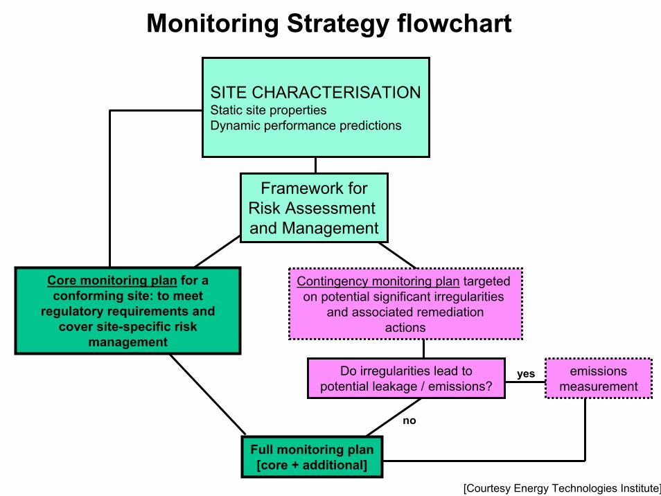
SITE CHARACTERISATIONStatic site propertiesDynamic performance predictions
Framework forRisk Assessment and Management
Full monitoring plan[core + additional]
Core monitoring plan for a conforming site: to meet
regulatory requirements and cover site-specific risk
management
Contingency monitoring plan targeted on potential significant irregularities
and associated remediationactions
Do irregularities lead to potential leakage / emissions?
yes
no
emissions measurement
Monitoring Strategy flowchart
[Courtesy Energy Technologies Institute]

Conclusions Performance Verification
� Different tools separately or in combination can provide required assurance� Some sites can offer very high monitorability� �Perfect� matches difficult to achieve� Fit-for-purpose
Leakage detection/measurement
� Sampling issues need to be overcome
Long-term Assurance
� Post-injection monitoring datasets
Monitoring Plans
� Site-specific� Limited number of technologies� Core and Contingency elements
Acknowledgements
CO2ReMoVe FP6 project funded by the European Commission and industry
Energy Technologies Institute (UK)