o power lab power eleltronics lab., hong kong university
TRANSCRIPT

o
Power "
Lab power Eleltronics Lab.,HONG KONG University
FEtS-)r fTtEiE@ffiffimET'�&ffiHl

tITtTITTTTT!I--
TTTTTTTT
Course Overyiew
Electromagnetic interference (EMI) is an important issue for switching power supplyengincers. Switching Dower supply is a main contributor of Eivll in an electronicproduct. Many countries have regulations to ban electronic products l.vith high EMl.Al1 EiVIi problems must be solved beforc the product can be put to the market and thisoften becomes a bott le neck in the dcsign process.
EMi in switching power supply is often regarded as a difficult problem. There is alack of concept and understanding for switching power suppty EMI issues. Generaland convcntional concepts are not always applicable because of the specialenvironment in a switching power suppiy. Also EIvII components required often takeup space and increase the product cost. Ensineers often find it difficult to strike abaiance between EMI performance, cost and size of the product.
This course wili help you understand EMI problems in switching power supply. Youwill learn to solve the problem effectrvely wrthout using extravagant methods such asusing expensive hiter components. Very practical methods together wrrhcomprehensive theories are presented in thrs course.
Abottt the speakers
Franki N.K. Poon d&#ffi) started his career in Electronic Engineering in i985.After some experience in the industry he obtained a Degree in Elecffonic Engineeringin Ciry Universiry Hong Kong. Ile worked for ASTEC and Artesyn TechnologiesAsra Pacific Ltd on many switching power supply projects. He joined the PowerElectronics Laboratory in Hong Kong [-iniversity in 1999 and is now the TechnicalDirector of the Power Electronics Lab. His research interest includes electromagneticintert'erence, circuit topoiogres, PWM switches modeling, zero-voltage switchine,power f-actor correction and synchronous rectif-rcation. FIe is the inventor oiover 10US patents and a number of pending patents.
Bryan l t .H, Pong (/ f tEel jq$) received hrs BSc degree from the Universiry ofBinningham and his PhD ,tegrce tiom cambndge Unrversiry in the U.K. Attergraduation Dr. Pong spent a t'ew years in thc Eiectronrcs Industry. He worked iorNational Semiconductor Hong Kong and ,A.STEC International. Now he is anAssociate Prot'essor at the Hong Kong Universiry. He founded the Power ElectronicsLaboratory and is now leading a team to carry out research in switching powersupplies. His research interests include synchronous rectification, EMI issues, powerfactor correction, magnetic component design and soft switching. He has co-inventedmore than 10 US patents and a number of pendirlg patents..

Power.Lab HKU
1 Explanationof Electromagnetic Interferencejk (EMI) in Switching Power Supply
Speakers
Franki Poon, Bryan M.H. Pong
Preryred bv Ftanki Poon & Bnan Pong
EMI in Swilching Power Supply
PowereLabThe Power Electronics Lab., Hong Kong University
O copyr ight 2002
ww. ee e. hku. hUpo||er e l eclron i6 lob/
PowefLabHKu
t
I.!*|* 1 brief introduction to the POWef eLab
Our Mission : To advance switchinqpower converter tech noloqies
' To develop excellence in powerelectron ics tech no log ies
. To apply the technologies to productsand foster cooperation with industries
Contact Pemn : Dr, Bryan M.H, pongPower Electgnics Lab,, O€partrn€nt of €l€cbict & Elstronic Engineering,Hong Kong University, Pokfulam Road,Hong KongTel: (852) 2859 7099 Fax: (852) ZAS97O99 or 2559 8738€mail r [email protected],hk Web site t ww.#.hku.hvFnw_elxtonc_/ab/
Prepareti bv Franki Poon & Bruan PonsE'lll n Switchtng Power SuoDiv q\ew.lce.hku.hhurwet eiectronrcs lah/ l

Power.Lab HKtl
Ottr work in the Power e Lab
Hiqh Power l20WAC/DCadapter Platform
Half brick DCDCConverter Platform High current Converief
Platform ivs 2004
ACDC Convefter8atterv charger
Pladorm ivs 40A platform 12V 65W
Preporeu bv Franki Poon & Boan Pong
EMI in Stvirchinq Power Supply
4.5kVA Power AmpliFier
*vw. ee e. h k u - h lv po w e r _e I e c r r o n tcs-�i a b/
PowefLab ilKU
L!'hat :loLt are going to learn today. .
Easy - EMI Basics. What ancj iiow peopleiest your product.
Not so easy - General attitude cf an EMIengineer.
. Difficult - How EMI is Droduced.
. More difficult - How EMI comes and qoes.
ffi{:lr2 Ar \ . -eee.hku. tNDo\ r ' . r : t cc r ro rL . : ,dD/ J

I
IIIIIIIIIIIIr|IIIIItt
PoweFLab HKU
I=qlm Basic B locks
- |w
. Every EMI issue has the following 3basic blocks
ffi Ptepared hv F.anki Poon & Bnun Poaq
Ji* E.V/ in Swirchtnq Power Supply tww. ee e. h ku - h A powe r _e I e c t ron tcs.ml a b/
I'loise Sources
r--D+-r-
ts;-I-
+
i x aI
. Switchino voltaoe and ftirrent waveforms in aJ J ,
swrtcnrng power supply.1 - "no fe t t hv : "onxr zaon,_ t : lnan r , iq
EMI n Switchtng Power SuDoir' :n"w.eee.hku.hl4power 'tiectroncs iob/ 6
v@Ir'rAL{14"7
r++D"+w

100
0
r00Eridge
EMi in Switching Power Supply
Power"Lab HKIJ
It - - .-qlg WaveJbrm prodttces Jiequency spectnrm
r l&l lokHz iooMHz
. Continuous Flyback
10
/ ,/ : )l l 1t . :
1 ' : :
. Discont inuousFlyback
1 0 A 1
, /l_l L_Prepared hy Fronki Poon tl )ruan ?uq
[, l l ] in Switchinq Power Suoot, t .ww *e nku hiifpower tittrtrittt ,tD/

tttII
FTITII-l
TTTtTTtl|
l|
l|
tI
Powerrlab l lKU
Effect of duQ q)cle
:r. Duty c/cle = 0.6
w\|.eee.hku.hly'power electronis lab/
Duty cycle = 0.2
Prepared bv Franki Poon & Bryan Pong
EMI in S\9itching Power Supply
'rfrt dvidt),oo
n i-r t,&.tl "t:l l l l ' � -
o l l l l
. 300ns rise and fall time
f i . ' - "nu.n, \ t F\nKt Paon & 3nun p,tny
IJ f .W tn j* t tcntnq I 'a*cr ;uca; ' . 'e\e\|.eee.hku.hkiu)\eer J/ectr!)htcs,ab/

IIIIIIIIIIIrIIIIIIIII
a
tn-
PowercLabHKu
t
I
nls Snubber circuit reduces dv/dt* t *
tuh,\Wf G lA"fi)A
Prepored b.v Franki Poon & Brya Pong
EW in Switching Power Supply ne\9.eee.hku.hvpo\9er-electrcni6-lab/ ll
PowefLab HKU
I
I
I
I
It[otes on l{oise Sources
Voltage and current waveformsNoise sources in switching powe_r sup.ply haslittle effect beyond 200MHz Yg"Sbfrt ,Waveshape affect base band frequenciesRising and falling edges affect high frequencyspectrumDuty cycle has little efTect on the spectrum
H{!r??reparel hv Frcnh Poon & )n'un P.nq
E,lll in Switchtnq Power Suppiv ww eee h*u.hltoower :lcctronics ldb/

IIIIIIIIl|
l|
tTl|
IttTtttt
, ^'NatLttt l"*|*, Coupling Paths
.&l+t
Contact Coupling
.1 taur* l hv Franx t Pn"q & 3n n t , tn t
E , l l l i n Swtch ing Power Suoo iv
thl{W*w.'*w
PowereLahHKu
r Every EMI issue has the followingbasic blocks
Prepared b1' Ftanki Poon & Bean Pons
EMI in Switching Power Supply wweee.hku.hUpower_elecrrontulaht lJ
Basic Blocks
,6e\e cce hku hlvtN,wpr -lecrntnrc.; :ao,

Receiver B,rL
. Standard test equipment set up' Conducted Measurement set up. Radiated Measurement set up
t2+ E4g,%*d W-
Preparcd hy Frcnki Poon & Enan Pong
EW in Swilching Power Supply ww.eee.hku. hApower _electroniu _lab/ I 5
Power.Lab HKU
Electromagnetic Emission(Our Interest)'
at u] Pful fepdrcu .v r f lnx r ! ' tu ,n & 6AJn t 'on t
EMI in Swrtching Poqer SuDplv
Electromagnetic Immunity
EMI standards
,ww.eeehku.hbpower . : lec : rnn tcs- tb t l6
Power"Lab HKU
lil ?,1 *+t41 .(rft^*e'
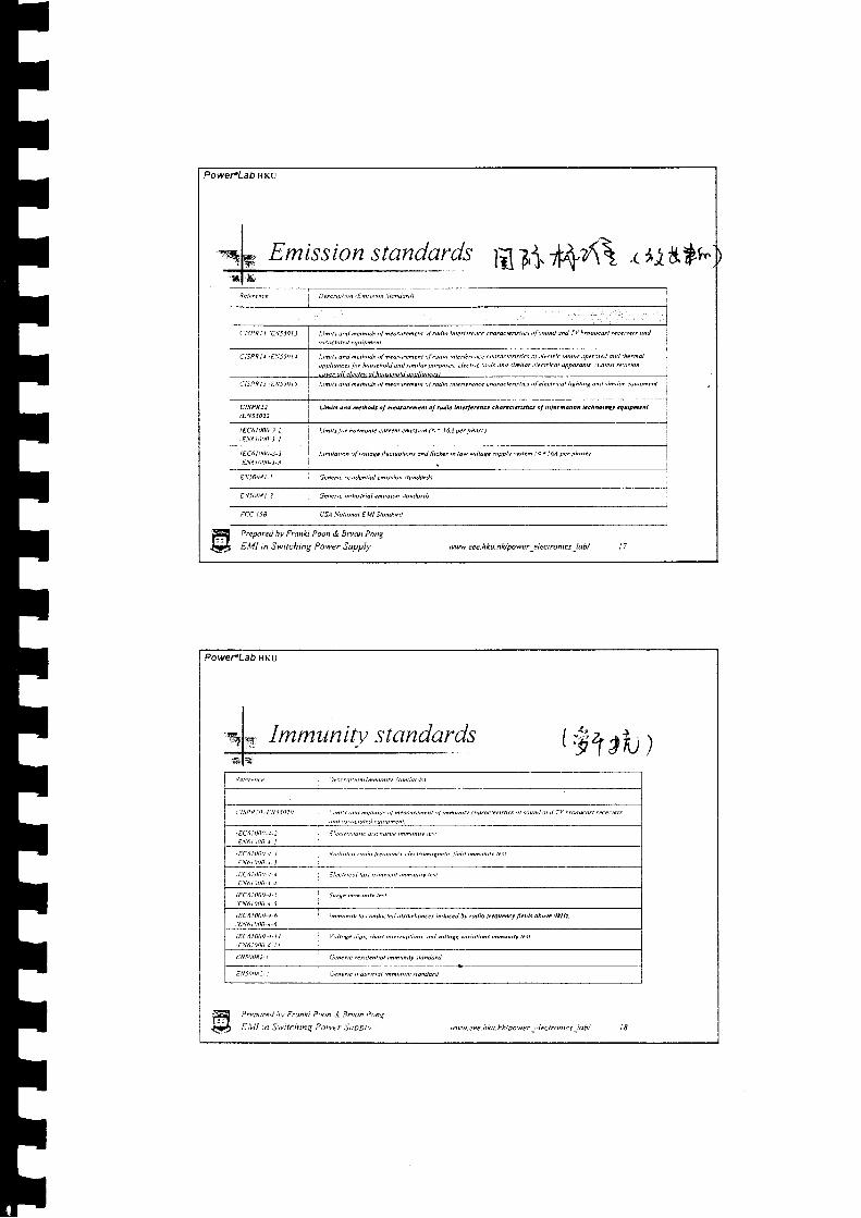
t. inilr dnl nethollt , l nealtrehent oftd.ln uilelercnce chatoct.rft ict t)/ nilod ond Tv h.!Nd.a!t tutetw,r dnd I
dti lrctotcl.qrtnhent
Lthttt orl nciln'ds ol rn.diut.hen' itulb ut.rt ircnce.hdrocteiltt ic\ al 2l..tt i . 6oxt..percted onil lhenol
nptl ioilce.\r '.hot.eholJdnJ.\inii l tWtpo\as.rl.?ntchnltdndtinilorelz(tt i.oldrya.on6 !Latertrertsnta
Lihilt a^t n.tho& ofh.!ss,.d.rt oftilb 6t..l.t.,E..h..rct.tuncr ofinlotd.do, t.ch^otos.qrrya.rt.
LidB lir harilo,tc tilteht en'rsirn (<= I6A pet thai,)
Li^ilahon ot v' itdq. lhtcltotio, \ dnd l l ick r t n Io|' vohoa. .i l t pplv .tvst?6 I < - I 6/ p. t pha.. )
1
j i lqrc reiltund eaisna s&,.lailI
Genenc indusniol .6isson ilondolds
FCC tSB IJSA,Yotio,o! EMl Sb,erd
CISPR]2
/EN55022
Prepared bv Franki Poon & Bryu Pong
EMI in Swilching Power Supply ww. eee. h ku. hlu wwer pl ec | rcn t6 k tbi 1 7
Emission standards
Power.Lab HKU
(91 , ta)
Prepdred bv Fran|i Poon,l :lfron l>.nt
E,lll ln Switchinq Power Supor,'
Immuniv standards
i teto'ncc ietctlrto"tl i lhwtN Stdnloil.\ l
' t S t a ) t ) . 1 : , \ j 5 0 a 0 : - t d 1 ^ o n t d e t h o t \ , t n e o s i l . e n e n t n t t ^ a u n t b - . h o t . . t e i l s i l c . \ o t . r ! , l o n l i v r t @ d c o s t , e c e t , e , '
rnl n,\.a)ctote, euutDnenl
iEC6ltM)-1 2 ]iltxr,)eonc rtuilltce nnunilr !e\F.\61iilil) J l
iEC6 l0a0
:Ec6lti l i l)-r-r t le.n'.ul iult t,antteilt 1nnu,ilv e\l
E.\alat\),r I
iEc6i0oil-!'J Surt. xnnu"n tut
EN6l 00il-1-5
I EC6 I 0oa-1.6 innunt t! b . ontucle J ti (n,hoDcet is4rc.l bv til)o liequ.hcy fi.lls dhoe. 9 kHt
lEc6l0tnr-l 1 V,ltaE. Jip.t. thoil :"t.truptn'm onJ 6hog. vanotio,i 'n6u,tN tail,EN6tA0t ) -J - t I
8N50082 I Gen..t. t..tiJ.htbt tndu,ily tk "ldtd
E,\5lt)N: - i;eil.. ' . rru,trtal tdnntN \to,darl
'nvw eee. h ku. hll power -'4 ec rron rcs _i ab/

all
IIIIrlItr|tIItl|
l|
tItl|
I
Power"Lab HKU
Ivleasurement - Ltse what type of equipment 'J
Spectrum Analyzer
@ cheap
i O One is enough - 10kHz -1GHz
@ Less accurate
EMI Receiver
@ Expensive
Prepared by Franki Poon & Bruu Pong
EMI in Switching Power Supply
o rwo are needed - l8[Hl:tt#:t
@ More accurate
nvwlee.hku.hUpower _electronia -lab/ : 9
r\L ,
Powerlab HKU
Measurement Set Up - Conducted (< 30MHz)
Prcpared hv Fronxt P.on & Sn un Ponr
E,VI in Switchinq Pcwer Suooly
it** No Shield Room is Nceclcti rr
0.8m(CISPR)
Ground plane 2m x 2m(CISPR), 2.5m x 3m(FCC)
arw t:ee. nku. nidpo wer _.i ectft)n rcs.1t:rth/

Power"Lab HKu
Measurement Set Up - Radiated EMI(> 30MHz)
Measurement distance L = 3M or lOM
otrr
l m - 4 mto obtainMax.reading
To Re€eiveror Sp€cttumAnalyzerwithcortutionfador
Prepared hv Franki poon & BryM pon"
EMI in Switching power Supply w. eee. h ku. h Apow e r _e I ecrrcn i6 -l ah/
PowercLab HKu
i
i A: . I: l m l: *:
J " ' L
Boundary ofarea rto be free ofrellective objects
Max. antennadimension
Anechoig chamber rs Needed in practice!l
8 er.parpu i,v Frunxi p.t,n e Bnun pooq
V E,Vl in Suttchtng powlr japp11,'tww. eee. h ku-h lvpower jleclron rcs lab/

Power.LaO rrKU
Radiated Set Up - diagnosis
. Anechoic chamber fil led with ferrite absorbers toabsorb EM reflections
' Small TEM cell provides convenient way to diaqnoseEMi problem
w\|. eee. h ku. h klpower,e lecrron ru I aht
PowereLab uKu
fuIeasrtrement - Limit level
Can ;,tcu make anamplifier wh tch receivessignal from 150kl1z to1Gl-iz at 2A0uV srgnallevei ??
\b.4$
t ,< : r , t t t : t t , i r - ' J
ClSPR2l conducredemission linit
I v \ | . cee .hku.hVra \ r r r

PoweraLah HKU
Measurement - about errorv^k
According to "EMC for product Designers" - Tim Williams
RF meuurinq recei'er - +1- ).iciB (worse fitrspectrum analv:er)
I m p e d o n c c a i s m r r c h r . l d B
,4 nlennq /, ldB
Antenna cable +/- 2.5ciB
,4nechoic chamber +1- JdB
'""ifiiirllp-:nr.\ i,z)r''-'�dBe{(w ' ' '
,o,u, = L7 dB Iww. e e e. h ku. h U po|9e r -e I e c t ro n iu _l ab/
$A\Prepored by Franki Poon & Bmu Pong
EMI in Swilching Power Supply
'rv
/ , 2WM
b dhzu
Power"Lab HKU
I
I
r
Spectrum Analyzer is cheaper for inhouse pre-compliance test.Conducted measurement is rather simple.Radiated measurement is diff icult.Different test Laboratory will give youdifferent results.
tfl-r.t1 - L p d r 4 d \ " F r l n h P 1 " n . i 3 ^ t n ! ' ' n \
i . l l l tn Switching Ptwer Suoptt
luleasttrement - short summary
. *w eu nku a lupr twer ' ieer runns .aa

tttIFtttITIttItttIttt
n6-nZrf '
PowereLab HKU
Prcpare.l bv Franki Poon & Bryan pong
EMI in Switching Power Supplv nvw.eee.hku.hldpower_eiectoniq_lab/ )7
Mort I*portant Concept - LOG Ai t[ft
are in LOG scale,l ies in our mind that
Reading = 20Log(M"ot":nd )dBuv10-b
Can you imagine what a number wi l l becomewhen i t is d iv ided by 10-6, then take LOG, andf inal ly mult ip l ied by 20 ??
FI{_!,
PoweraLabHKu
Most Important Concept - LOG & Sum
500uV = 54 dBuV
1000uV = 60 dBuV
2000uV = 66 dBuV
500 uV + 1000 uV + 2000 uV = 3500 uV = 71 dBuVGeneric human intuitive comDarisonCompare linear result 3500 / 500 = 7 times
Compare LOG result 7US+ = 1.3 times
ffi ,-,oareahvF,unkipoon,i,"-"-what dogs i ';t ir:nes tell urs
'?
l?+ E '\ll Ln Swlchtnq Powcr ,lypply \| cee hku npy)||er etectonrcs tab/ )8
,NojAe r-l|*. Y4'/-&T-

PowefLab HKU
Most Important Concept - LOG & Subtract
3500uV = 71 dBuV
2000uV = 66 dBuV
1000uV = 60 dBuV
3500 uV - 2000 uV - 1000 uV = 500 uV = 54 dBuVGeneric human intuitive comparison tells us
Compare linear result 50.0 / 3500 = 0.143 times
o';;:,:;ffi o l*;p* :* \I- ?
{l} 6,,tZt i".S.trching Power Sr
Powel'Lab iIKU
P,cpared i t y F , nx t Pooa. l s^un Y,n \
Et l l l tn Swi tch ing Power Supotv a\!\.ccc.4ku.hlvpu|'cr !lcctronrca lah/
LOG Reading - an example

TITITITITI
ITT-
I-t
I-t
TTTTTTr|ttTtt
PowercLabuKU
effect of the transformer
9 -fr'
MOSFET
PCB
Aux,
a
sr6 r rd r gd z rd zsd r rdFfrquency (Log scale)
- C|SPR?2 canductive class B Imit line- Oiginal Nois€ Lavel- Xfomer naise eliminatad
Prepared bv Frahki Poon & Bryu Pong
EMI in Switching Power Supply \w\9.eee.hku.hUpower _electronics _lab/ 3 I
Example - eliminate
Conclusion - Little effect
PowercLah HKU
effect of the I,IOSFET
l d ' l d . r d . : ' d z , s d r r dFBquency (Log scale)
-- C|SPR22 conductive class I limit line- Original Noise Level- MASF€T noise eliminated
, lF Example - eliminate
Conclusion - Very Little effect
'"6F€TPCB
Aux.
.g
u,l
rq
z-d
l . ! - i l . "eoar "d hv t . tnk i P ,x tn . i Baun ? . .n t
i * - , t .V t :n Jwt tchnq Pcwer Supptv .w (ce .hku ah Dowyt " lec r r ' tnus .ab ,

Power.LabHKu
effect of the PCB
srd ,.Ld srl z'6 z.s6 rrdFCquency (Loq scab)
- C|SPR22 conductive class B limit line- Original Noise Level-- PCB naisa eliminatad
Prepare<l by Franki Poon & Bryu Pong
EMI in Switching Power Supply ww. eee. h ku. hVpowe r _e I ect rc n i q _l a b/
Example - eliminate
Conclusion - No effect
PowercLab HKU
Example - eliminate the little and
Conclusion - Hopeless, stil l exceeds the
the very little
l im i t
ItrlrltI
Prepared hv Fnnki Poon & sflan ponq
[,lll u Switchtnq Power Suprti,,,
srd , .1d r sd rrd zcd rrdrequoncy (Log scate)
; C|SPR22 conductive ctass I timit tine- Onginal Noise Level
' Xformer & MOSFET noise eliminated
vrtw.eee.hku.h*/powert iecrmnrcslah/ _r l
LISN

ETFFFF
I
FTTTTTT
Powelrlab HKU
in a professional way ?
Prepare<l by Franki Poon & Bryan Pong
EW in Switching Power Supply ww. eee. h ku. h Apwer _e I ect rc n is _l ab/
Example already
So HoPtess
Power.LabHKu
Xformer
MOSFET
PC8
Aux.
s
trs9
l d ' l d u r d z , d t s dr@@tLq&*)
' C|SPR2? conouctw de$ I Id lhe| - OilEntt Mtse Levd
- Xlffier onlyMOSFET anly
- PCB onty
Prepared bv F,unn Paun & Sntn P na
EMI in Switchins Power Suppiv
minute.
LISN
'vrew tce nku.nkJdtwer 'l.crnntc\ 'Jh/ j6

tIll
tTTTTTTTTTTTTTTTTt -
Power.Lab HKU
We're wrong fwice - eliminatethe No Effect
Preporey' by Fronki Poon & gryan Pong
EMI in Switching Power Supply
$ *l | | l lr li " i * I I l: t I' 1 I"liiliil'M[l!rin,,,
' l ' l l t l l i l i i ir r d ' r o , r , d
- C|SPR22 ctu&nw <- Ong,rdNoiseled- Aux. 6tY
w\|. ee e. h L\. h ld po\9 e r _e I ec ! ro n is
Power"Lab HKU
flantXformer
0I'4OSFET
ilPCBI
R i n n n I
e
PCB|l
J't(JJrtr |n&
XformerIl
R i nnn I" . ' Y '
I|
Xformer is importantPCB is important
Wrons three times ?
f f i P--oar"J w f , tnk; P,, tn Li d.on . \ )ai
r t : . t t t : n ; ^ r c h i n q P c w t r ; L D p r wwcee-nku.hAoower !lec!rontcs iab/

PoweFLabilKu
-tyyttilatp tfrl&
There is a dominant noise mechanismor path - Wrong!Some other noise mechanism can beignored as it shows no effect - Wrong!Yesterday EMI solution did not work intoday's problem - Wrong!
Prepared by Franki Poon & Bryan Pong
EMI in Switching Power Supply w. ee e. h Sr. h Upow e r _e I ec t ro n ics _l a b/
Wrong Concepts
Power.Lab HKU
r " You wil lyou haveproblem"
not see aelrminated
result untilthe LAST
ffir:!tPrepdred bv Frdnki Poon & Eoun Pony
EMI n Swtchinq Power Supptv
Peter Bardos
Right Concept
:vww.eee hku nivoower erectronrcs lobt

PowefLabHKu
I
4s Remember
r Two equal noise level add togetheronly make a 6 dB difference
Reading = 2lLog(Muot"nd * y"otured "^
u '-)dbuY
$Reading = (20 Lo g (yryry5 + 20 Log (z))dBuv
[ 1 0 - oI
Reading = (20 Log (ryT"!"d ) + 6) dBuV' 10-o
ffi PrepareJ bv Franki Poon & Bmu pong
Ql EW i, Snirching Power Suppty wu e e e. h ku. h Apone t -e I e ct ron i u -l ab/
PoweFLab HKU
l . - t ' l r 1-EL IaKe a break" l"x{-
' \ r
\ ; r i \ 1 , t r* i * ' , : l' 1 i i i . ; l t l i l i I l l l , r n t r n v t. ,,^, ".rv{r *{uuSLlllil ,
f i c - p a . * t r u . i , o n l i l a t , a i 3 r . - a ' , . 1
i ! r4 g.t l t : i l S* t tchnq Ptwtr . tanL. ' tw \9 .cee-hku.n tuoower l tec t ron t r lab / J2

Htlt \vww eee hlra-hUoower eiectronics lah/ .14
detail
Power.LabHKu
LISN - a little bit more
" " " ' u s N
5OuH
.T0",i l l ki l
50 Ohmrcelver
50 OhmrKeaver
'*'T'l itl
IIIIITTTI
_4
I!
Il - 'tl =Tt -Tl -Il =
Tl -Il a
t -
FFFI
Line Impedance Stabilization Network - ac Only
Prepared bv Franki Poon & Bryw Pong
EMI in Switching Power Supply w. eee. h ku. hUpower -e I ectrcnis -l a b/
Simple Mission -
5o a to Earth 5oo
Power.Lab HKU
Picking up the noise - LISN

PoweFLab HKU
to line noise
I n p u tL i n e l
To50Ohmreceiver
Termlnrted
by 50Ohm
Idif f
Differential modenoise
v
Esrth
q,
fu^ InPut
Prepared by Franki Pmn & Bryat Pong
EMI in Switching Power Supply wvw. e e e. h ku. h Upowe r _e I e c t r o n i u _l a bt'
LISN - detects
PowefLab HKU
*to earth noise
L i n e l
i
4LTo50O hnr€ceiver
Terminsted
by 500hm
l c o m l
Common mode noise
l> r "par .J 5 c -nh P " 'n * J r . r r r ) ' r c
E,VI in Swi tchnq : ' tqer Su7orv
- detects
*vw e ee. h ku. hidpower _c I ec tron tcs'�l u h/

T!TTTTITITTT!IITTllTTI
PowefLabHKU
Predicting noise to space- Absorption clampl l ove a lone the input c lb le
H l . r to rca h t F .anx t 1 . " ,n & 3^ .an ! . ,n t
l i4 r.t l l n Switthuq Power Suoort '"ww e*.hku.hUpower electn)nrcs lab/
PowercLabilKu
space - Antenna
ot " ' 8 l l
' : t r 1
7(E
300MHz (log scale)
Prepared by Franki Poon & gn-dn Pong
EtVl in Switching Power Supply w-eee. h ku.hApower el ect ron ie labt'
Picking up the noise
PowercLab rlKu
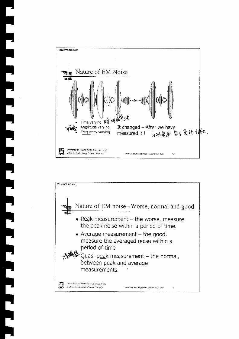
rime';ryins SttdAmolitude varyingFEglgn.y varying
It changed - After we havembasurio it r -:,ri3x EnAh {
Prepared bv Franki Poon & Bryan Pong
EMI in Switchinq Power Supoly ww. eee. h ku. h Upow er _e I e c r ron iu _l a b/
Nafure of EM Noise
PoweFLah HKU
Nature of EM noise-Worse, norrnal and good
P-gak measurement - the worse, measurethe peak noise within a period of t ime.Average measurement - the good,measure the averaged noise within a
H€t ,Nw. eee.hku- hApowet _eIectonrcs -lab/
oeriod of t ime
rnfiSqgg;.1n*k measurement - the normal,between peak and averagemeasurements. 4
, - ' " o u r - t t " v ' . t n k r . ' . , , 4 i , 1 r r n P , , a -
EL l l n Swt tch inq Power Suoo iv

Power.Lab ilKr
Noiseafterdetector
Peak result
Quasi-peakr€sult
Average result
4nb
Prepared bv Franki P@d &. |ry@ Pong
EMI in Switching Power Supply ww e e e. h ku. h Upawer _e I ec ! ron6 _l ab/ 51
Peak, Quasi-peak, average
Time
PowefLabHKu
Resoiut ionSandwrdth Amp
P:flk oa EnvelopeDeteclor
(}'{(h'0+
lF0$,040Sclcctine$unng
lrequencyX - r r i s
Simpl i f ied Peak EMI receiver
Prepared hv Franki Pnon & SNan Pong
E,lll in S*,tchinq Power Suppiv
Peak detector - simplified
"rww. c e e. h ku. hfu FD\| er _r I ec I r o n i c s,! o b/

PoweFLabHlKu
Quasi-peak detector - simplified
Mixer Resolul ion
Bandwidl.hQuoi-Peal
t
, t tA'{. 0 . 5 H 2
|\rerDetector
CI"0$"{}f
M{HDSclectmc6uringl'rcquency
X-uls
Preparc<l by Franki Poon & Bryan Pong
EMI in Switching Power Supply
Quoi-Peak EMI receiver
w. eee. h ku. hUpowe r _e I ec t ron ia _l a b/
PoweraLab HKU
y\otuqilRl
What happens if the noise occLtrrence time isless than the charge time ?
Prepared bv Fronkt Paon & gruon Pong
E,W in Switchnq Power Suopiy '
Quasi-peak constant
. \ww tep .hku .n fu pDwcr : lec t r , tnu t ,a i t i

Power.Lab ilKu
fv l ixcr Resolut ion envelop 0.5H2Bandwidth r{mP Detcctor LPF
Sq0@0+
MMSclcctmeaunng
lrcqucncy
X-rr ls
Prepared bv Fronki Poon & Bryan Pong
EMI in Switching Power Supplv ww. eee. h ku. h lt/ power _e I ect ro n i a -l ab/
Average detector - simplified
PoweraLab HKU
Dan't forget every detedor has a chargingtime constant.
Prepored bv Frunki i>oon & 8ruon Pong
E,l l l tn Switchng Ptwer Suooiv
constant
QP-letectar l 0 - l 5 1 k l l z t t 1 5 - . l q M l k j 0 - j ) o M H t 0 l - t c l l z
6dB handwdrh o.:kll: aill. l2qktlz l:1kllz
Chorget ime | , . l
Dischorge timc
ww eee. h Lz. hlv pawer r I ectron r cs _t ob/

Power"Lab ilKu
does a signal exist
Period for detection ata ceftain frequency
B WI = _ l' chsrge ' . tveep
r trop J lnt{rdl
tSo lc - -1oAFor conducted EMI rangeand sweep is ls
J = l l l u c' c h a t g e
' " ^ :7t { l4f t \L"A;A
ffi PreOare,J ty Fronk Poon & \Nn Pong
L;iA, EMI n Switching Power Supply ww. eee. h ku. h ltl powc r -c I e c t ro n | 6 -i db/
Detector - how
PoweFLabHKu
Detector - fast and slow sweep
Sweep time = 10 s
S w e e p t i m e = 1 s
Preporey' hv Fronki Poan & Saan P,)ng
EMI in Switchinq Power Suppit' M. e ee. h ku. h LJ g)we r -e I ec tr o n t 6 _i o b/

PowePLabHKu
Prepare<l by Franki Poon & Bdon Pong
EMI in Switching Power Suppllt ww. eee. h ku, h Upowe r _e I ec t ro n i q,l a bt
. LISN, spectrum/ receiver, antenna, absorption clampare introduced.Peak detector is used for screen display as it givesfastest response.
Quasi-peak and average are used in most standards.You can cheat the detector or display screen if thenoise pop out faster than the charge time.Don't be cheated by the screen if sweep time is toofast.
I
I
summary
PowefLabHKU
Any Short Question?
Prepored bv Franki Poon & Ennn i''tng
EMI in Switchinq Power Supplv
, , ' . , ' " , ] , t , t '
' . ^
i' iulr 'ri."l / ili {l1,.1l s0 ixj\t - , v v, . *
ffiv w|weee.nku.n lopowel_e lec tn , r rcs ldh / 60

Power'Lab lrKU
f ' . t I tInvisible coupling - capacitive
Jr%v* 1t5Og
Does a capacitive objed work like a capacitor in acircuit ?
Prepored bv Franki Poon & Brynn Pong
EMI in Switching Power Supplv w\9.eee.hku.hl</power electrcniq lob/
Power.Lab HKU
spectrumanalyzer
co
e r & . . . 1 r r r / t d z t ' dFqufrcy(Hz)
+ Simulatad result'' Measured rcsult
M ulu al Ca pac i tive Cou plinq
PrPporel hv Frcnn Pnon d Bruon P,nt
ELll n Sw,itchmg Power Suppiv
Capacitor is capacitor
.t\w cee hta.hk/po9|"r _zlcctn)nc\ _.,tb,

Powel€Lab HKU
I-qfry Capacitor of course is capacitor-
. The above experiment actually does not intendto prove a two plate structure is a capacitor.
r It proves two separate physical objects canhave effect very much like a simple capacitorcoupled together and can give accurate resulteven the two separate objects connected to amore complicated circuit.
. Don't forget a pow€r supply is a complicatedcircuit, with a lot of separate parts and traces.
-$ Prepared bv Franh Poon & Bnon Pong
# E.VI ' , Switching Power Supplv ww.eee.hku.hlvpower_electroniu -lab/ 6J
PowePLabHKu
Invisible coupling - inductrwNW
spectrum Do i pick upanalyzer SOmething
here ?
Prepurel bv F,onn t ,nn & Snon Puy
EMI in Swilchnq Power gupplv .61" lee hku ippu\rcr .lectronrts i,.til

Power.LabHKu
Mutual inductive coupling - transformer
o..l /->i ( . / \t \ r c m lv
M
r * z '
- " [ n , 7 ' ' . , t " lL*tM_trn"_,""0=%ltoo ihd
-hd I
Prepared hy Frmki Poon & Bryu Pong
EMI in Switching Power Supply ww.eee.hku.hUpower-electrcnis_lab/ 65
Power.Lab HKU
Prepar"d hv F.anki Poon & Boan Pong
EMI in Swilching Power Supplv ww. eee. h ku. h la power -el ec tron tcs _l ab/
Indttctive coupling - equivalent model

r|
Powertlab t{KU
tVutnal inductive coupling : transformer ?
Fqufficy(Hz)* Simulalad resultn' Measured result
R &&QhN,
Mutuat nductvecou,tins
Prepored hv Franki Poon & BryM Pong
EMI in Switching Power Supply w w. ee e. h ku. h Apo wer -e I ec t rc n i6 _l a b/
Powe-LabilKU
You don't see this You see this
+)" v{; ; . v < + ; +
"if-' * . Y A
Y A \ <
Preoaryd bv Fronki Poon & 8^,an Pt)nt
E,VI in Switching Power 5ror1,
EMI engineer
'av*' cee.hku. hk/power _electronrcs _ldb/

III
PowefLabHKU
Prepared hv Franki Poon & Bfraa Pong
EMI in Switching Power Supply w\| .eee.hku.hADowerelectroniqiab/ 69
Any two nodes/ two objects, two components,two traces ... etc/ has an invisible capacitanceand capacitive coupling effectAny two segments/ two loops, two traces, twopaths ...etc, produce an invisible transformerand have inductive coupling effect.is there any combination of capacitive-inductive effect?
g
Reminder
PowefLabHKu
Simple idea ofElectro-Mag neticwave propagation.
H Prepare.l ov Franki Paon ,j. Bddn ltt)ag
EMI in Switchinq Power Suopiv
C ap ac it iv e - I nd'u c tiv e ffi c t
.vww rce hku.nltpower rlectrontcs tbt

PoweFLab HKU
Capacitive couplirg - trace to trace
sayCt-z = 0.lpf
Vst = 300V
Cu,,ois blocked byInput circuit & Bridge
Prepored by Franki Poon & Bryan Pong
EMI in Switching Power Supply ww.eee.hku.hUpower_electrcniq_[ab/ 7l
usN
Line
Inputdrcuit&Bridge
i** 6. . . . . . . . . . . . . . !
r l i] J ;) _
Un€ 2
Powe.LabHKu
Line 7 ,,Cr., As
Ct-z = 0'1Pf
Vst = 300V
At 150kHz
VrtsN= 1400uV
EN55022 B limit at 150kHz is630uV
500.a(\
500Line 2
V,,
v*n
x 300
Afr€odyercooh ffiiN hcdne d0.1d
Capacitive coupling - trace to trace
fr Prepdre.l bv fuanki Poon & Boon Pong
Ql E.VI in S*itchinq Power Supplv \ww eee.hku. hvNver electraner !db/

Power.Lab HKU
L I
IN
ryI
Prepare<l hy Franki Poon & Brya Pong
EMI in Switching Power Supply
C,
Itu
wv. e e e h ku. h ll po|9 e r _e I ec t rcn tu -l a bt 73
Capacitive coupling
Power.LabHKu
Capacitive coupling - which is bigger
L t
Itury
I
Iffi
CI <t Cz
P.epanl hv F.onn Pn,'n ti Bddn P1n\
EMI in Swtchinq Power Supply
Imagine C, approximate as thesum of all the capacitors
tavweee.hku.hUpower_electroniu_lab/ 71

itive coLtpling - trace to ground
say
C, = 0'l7f
i Vst = 300V
; - C. has a considerabie length+
'' between the plates but the4 surface on eanh is very large
Prepored by Franki Poon & Bryan Pong
EMI in Switching Power Supply ww. e e e. h ku. h Apowe r _c I ec I ro n i 6 _[ a b/
Capacitive coupling - trace to ground
/,.,r, 5 0 f )5 0 o
Assume
C, = o.l?f
Vst = 300V
At 150kHz
Vrtsr,t= 700uVEN55022 B limit at 150kHz is630uV
ffitlt
"Hxffied limit again IPrcporeu hv Franki Poon & Bnan Pong
Elvll in Switching Power Suppl.v ,nv*.eee.hku.hlt/power elqtronics tltb/ ;6

HVHF circuits
Hish 4Voltage
(
HisnFrequency
Preparel hv Franki Poon & 9nn Pong
EMI in Switching Power Supply ww.eee.hku.hupower_electrcnis _lab/ 77
PowefLab HKU
HVHF circuits - reduce to a sizeAs Small As Possible ASAP
Htlt
Prepared bv Frohki Poon & 9ruan Pong
E,lll in Swtching Power Supplv
RIGHT Wrodg RIGHT
.qvu cee hit.hlvmwer -:tecrronrcr _;ah. -R

PoweFLabHKu
Capacitive coupl-ing- - PCB trace rule t?l\'
\1(
- H I' l
i*f, t f"vq6N*--- H T' | q
tlrGood - small trace area, Bad - large trace area, asymmetrical.not enough separation and long
. connection wire.ljlnnelgcal, goodseparation
g Prepared bv Franki Poon & Brym Pong
EMI in Switching Power Supply wit e e h k u. hk/ po w e r -e I ec I ro n | 6 _l ab/
PowereLabilKU
trr'rtY"Inductive coupling - trace to trace
Although the loop has loW voltage, it generatesother kind of noise.
Prepared hv Franki I'oDn d Bdan Pong
EMI n Switching Power Suoplv ww.cee hku.hlt/power ..lectrontcs idb/ ,90

Powe,.Lab HKU
Inductive coupling - trace to trace induction
Prepared bv Franki P@n & Bry@ Pong
EMI in Switching Power Supply
say
L, = lnH
I'= lA @ 150kHz
V, r4= I ' 2 t f L .
V,ro = 940 uV
C, gives a lowimpedance path for theinduced current to flow
ww.eee.hku.hApower-electrcniq-laA 8l
PoweFLab HKt)
Inductive coupling - trace to trace result
V
say
Cx = 0'1uF
At 150kHz
VtrsN= 460uV
EN55022 B limit at 150kHz is630uV
l lrr.,r, = l--L, lxeaouv
1 5 0 + 5 0 + iI 2dic., I Verydoseto limiU
50C]
5 0 o
c
r\
H Prepak.l hv F,unki Poon & Bruan Plng
fif, C,Ut tn Switchinq Power Supp|v Bew.cee.hku.hlcoo\9er tlectrontc:,ub/

Power.Lah ilKu
Prepared bv Franki Poon & Brym Pong
EMI in Switching Power Supply wv eee. h ku. h Apowe r _e t ec trcn iq -i a b/
Inductive coupling - the trace itself
. Self inductance
PowefLab uKu
' '.-DorPd bv Frantu Poon & Bman p,ng
E,lll in Swtching Power Supplv
Let say
L. = 10nH
I'= 1A @ 150kHz
Vra= I ' 2 r fLs
Vra = 9400 uV
8N55022 B limit at 150kHz is' 630uV
ls it honible ?wv cce. h ku. n H Daa { _e I ectron rs _. ab,
Inductive coupling - trace induced voltage
Ls
c.Y
Ls

Power.Lab I|KU
Good - small loop area, good separationbefween loops, node terminated atcapacitor terminals
Bad - large loop area, short separationbetween loops, nodes are not terminatedat capacitor terminals
Prepared hy Franki Poon & Boan Pong
EMI in Switching Power Supply ww.ee4 hku,hHpower _electroniq -lab/ I5
Power"Lab ilKU
Tvpical copacitor and inductor parametervalltes
C = 0.085A/d pf t = 0.002/(/n(21/r)-0.75) uH Lm = 0.C02/(/n(2//D)-1+D/) uH
"^ry,i{1,tt5cm
J--. - LL I " " ' 1nn4
t lcm
Jr-
fr6=0.0885pf Lawsts=5.8nH Lfrawgts =15nH
f f i , ' . ,o"reu ou f ,ankr Poun & Bnun i , . ,nc
Ek t . \ l t tn Swttchinq Power jupph, tuw uee h tu nbp, twer : tec tn )nrc - dD/

I
PowercLab HKU
I-qh Short conclusion-
Prepared hy Frcnki Poon & Bryan pong
EMI in Switching Power Supply
Very small capacitor may cause seriouscapacitive coupling effectVery small inductor may cause seriousinductive coupling effect, either mutual orself inductive coupling.Very small pieces of object may causedevastating magnitude of capacitance orinductance.
www. eee. hku. hUpower _elcctronix _lobl t7
Power"Lab HKU
I
* nny Short euestion?-
i t l to " '&" " i , " ' '
i ' + , ' , . ;
i 1L't^l -^\, i JU] i ' , , . r ' . ^ i ' , t l * i
i,rSii ilj diiii0tiJi
f f i Prypdred hv F,uxt p. \ ,n e J^dn . , .nt
V t .Vtt n 5*i lching I 'ower jupplr*1r\'cee.nku.hvpo\ver-etectronrc-t_!oh/ Xg

Polver.Lab HKU
An obvious noise source - input ripple cltrrent
L3
c2
l
c,' l!
_Fr
.,\ {w)-f well known
\ equrvarence
L3 RB
I,,
i ----
: _ :' L ISN 1" " ' . " . . ' . . . ' . ' . . '
Prepared bv Franki Poon & Bryan Pong
EMI in Switching Power Supplv ww. e e e. h ku. h Upower -e I ec t ron i q _l o b/
ll
i
1--rJf= c , " c B :
(k ' (
l R . . :
If" ,-
t a' 1 . ' l I
l o , \1-
Powe.LabHKu
Input ripple current - simulation
Don't be scared bycomplicated circuit.You don't need tocalculate for theanswer.You ONLY need tosimulate it's result.SPICE, Maths o f t w a r e . . . e t c m a yhelo
! c )
ffi Prepareu hv Fronkt Po,)n & Bryan P,,n!
6b E.ul n Swilchinq Power Supptv ww eee.hiu hHpower -eIectrontc.r -,obt
Power'Lab ltKU
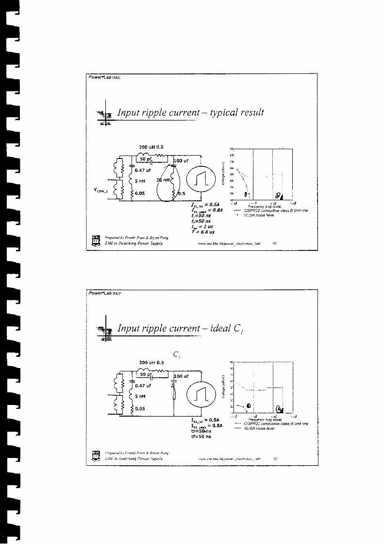
Input ripple current - Qpical resttlt
a
ftr-^, = 0.5Afrr-**= 0,8At,=50 nsIFSO nst * = 2 u sT = 6 , 6 u s
r . r d r . , e r . r d r , dFrcquancy (Lq *al6)
- C|SPR2? conductive class B limit line-- VLISN nolse /svs/
Prepared bv Ftanki Poon & Bryan Pong
EMI in Swilching Power Supply ww eee h ku. hUpower _e I ecrroniu _! abi
200 uH 0,5
O.47 ut
5 n H
0.05
Power"Lab HKU
ideal C ,
L l
20O uH 0.5
3
Irr-,n, = 0'5AIrr-oo, = 0'8Atr=5&nstf=50 ns
r . r d r ' r d ' r d r r dFEquency (Log *ale)
-- C|SPR2? conductivg class I fimit line* YLiSNnoAslev€i
i'repored hv Franii Foon & Enoa Pong
liMl in Swilchinq Power Supoiv
Input ripple current
O.47 uf
5 n H
0.05
lww. eee. h ku. h L, power -e ! ec rro n t cs _ obt

PowercLab HKU
fr.-11 = 0.5AItt-r.., = 0'8Atr=50 nstf=50 ns
r . rd r rd r . rdFrcquenc/ (Lq &ale)
ClSPR22 conductive class B limit lineVLISN ,oEa /€y€l
Prepared hv Fronki Poon & Brvu Pong
EMI in Switching Power Supply ww. e ee. h ku. h Hpo wel -e I ec! ro n i 6 -l a b/
Input ripple current -ideal
200 uH 0.5
Power.LabHKu
\ l ) 'hf '?rfr
n?rW*"
I.r_,n, = 0.5AIrr-, = o'8Atr=S0 nstf=s0 ns
r r d r . r d . d r . r dF6q@ncy (Lq *ale)
- C|SPR22 conductive class I limit line....._ VLISN rols€ /€vel
Input ripple current - ideal L,
O.47 uf
5 n H 2 0 n H
0.0s
fi P,eoored hv Frankt Poon & 7ruan Ponq
V EMI rn S\9ilching Power Suppiv ww.cee.hku.hHpower clectrontc\ iab/
, frh*)

Powe,.Lab HKv
C,, C,
L, less rms currentC2 2oo uH o.s C t
Not much difference
f51-16 = 0'5AIrr.-* = 0.8Atr=so nstf=50 ns
r r d r . r d r . r dFdquoncy (Lq *aE)
C|SPR2Z conductive class I limit lineYLISN no6e /eyel
ffi Preparctl hv Fronti P@n & Boan Pong
$ tW in Snitching Power Supply ww. e e e. h ku. h Apow er -e I ectrcn iu -lab/
Input ripple current - swzp
100 uf
2 0 n H 5 n H
0.5
Power<LabHKu
c2 200 uH 0.5
var"-,
Irr-,n, = o'5A
\.-t = 0'8Atr=5Otrstf=so ns
t t 0 r . r d t . t dFoquency (Loq wlel
C|SPR2? conductiva class I limit linaYLISN nols€ /€vel
Input ripple'current - ideul C,.again
'fi P.eparel hv Franki Poon & ENon Prng
fi E.VI 'n S*ttchinq Power Supplv avw. cee. h ku. h lt/ power _c I ec Fon | 6 _l d b/
IIIIIItTrITTttTtIIItt
PowefLabHKu
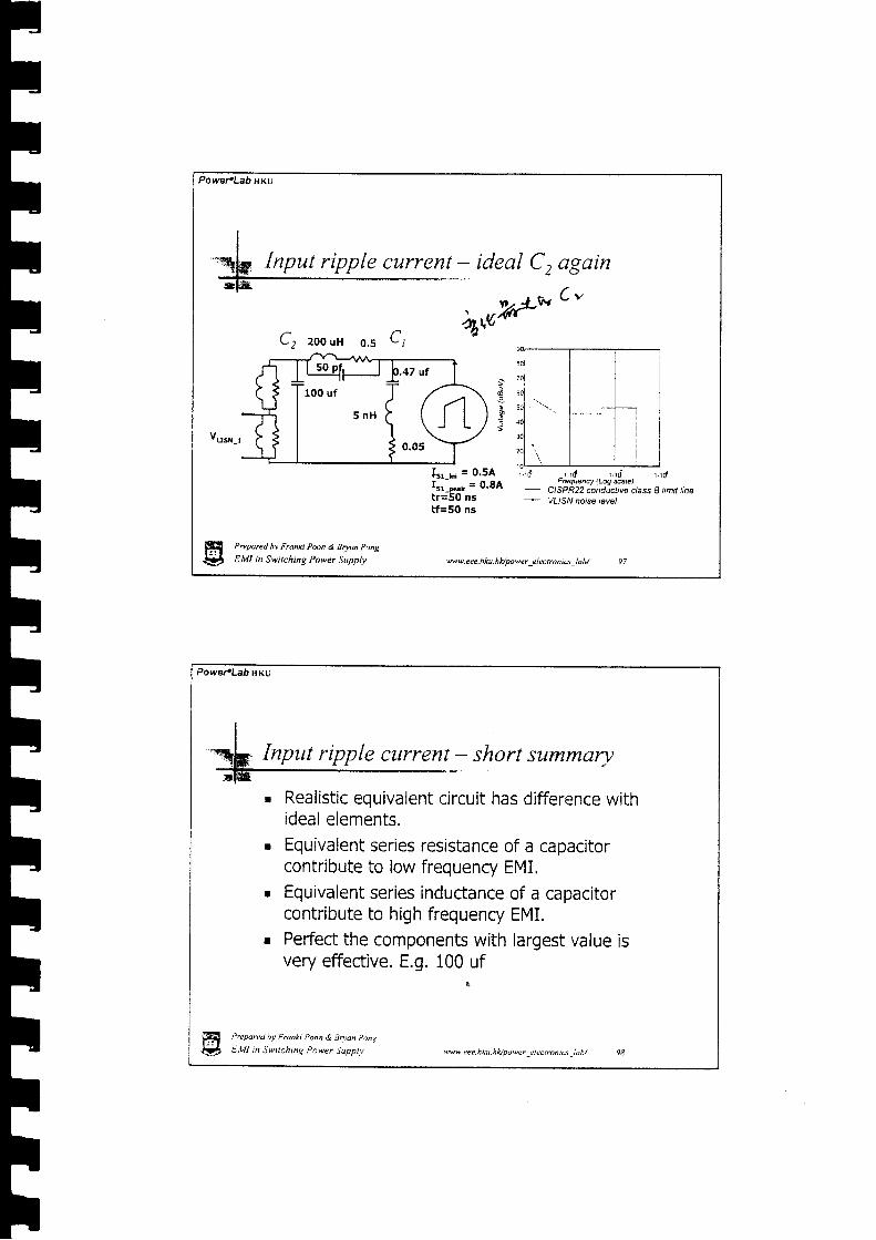
Input ripple current - ideal C, again
C2 zooun o.s Ct 4*W* ' -
Is1-6 = 0'5Arr.--., = 0'8Atr=50 nstf=50 ns
' ' ' d - t ' 0 . . , . ' d r r dFrcquency {Loq wte)
- C|SPR22 conduclive class E limit line.* VllsNnoisa /evel
Prepared hv Franki Poon & BryM Pong
EMI in Switching Power Supply ww. eee. h ku. h lt powe r _e I ecto n ta -l a b/ 97
PowefLahHKu
Prepared bv Franki Poon & Bnan Pong
EMI n Swtchinq Power Supplv ww ue.hku hllpower _(iectront6 -lab/
Input ripple current - short summary
Realistic equivalent circuit has difference withideal elements.Equivalent series resistance of a capacitorcontribute to low frequenry EMI.Equivalent series inductance of a capacitorcontribute to high frequency EMI.Perfect the components with largest value isvery effective. E.g. 100 uf

IIIhltFThFh
FIl-
FF
PowePLab trKU
L3
c2:
r f
I-{E
LISN
Add one morestage ?
Wait aminute I
Prepare<l bv Franhi Poon & Bry@ Podg
EMI in Switching Power Supply w. eee. h ku. h Apowe r _e I ec t ro n r u _l abt
Inptrt ripple current - two stage design
c5 ,C , c1
LISN
Powet LabHKU
There is a CommonMode Choke (CMC)
Ffl{:!t
Make use ofit 's leakageinductance !
Prepared hv Franki Poon & Eoan Pong
EMI in Swtching Power Suppll'
Input ripple current - make use of leakage
' -r anvwav.
dqffiiw$-
)w.eee hku hApower _electrunics _lob/

Power.LabHKv
50 uH 0.5 Z0O uH 0.5
vrr*-t
5lIrr-, = o'8Atr=50 nstf=50 ns
Prepare<l hv Franki Poon ,9. Bryu Pong
EMI in Switching Power Supply ww.eee.hku.hVwwer electroniu lab/
l0.1 u f -
(5 n H )
o.osi
fLr.PfryI Jtoo "t
\ z o " n 5 n H
i l'''
p.+z ut
t at /( l
I \ J
i o.ou\
,.\
I-/= Q ,
PoweFLabHKu
S
o
r . r d r . r d r . r d r ' r [email protected] (Log scaL)
'-- CISPR22 conductiva class B limit line.* VllsNnoise/€val
Single Stage Filter
Prepored he Frcnki Poon ,9 Btuan Pong
EMI in Switchtng Power Supplv
r . rd r . rd r ' rd r . rdFrequency (Log scale)
-"- CISPR22 conductive class I limit line* YtlSN noise with P & CM filter
Two Stage Filter
Input ripple current - two stage result
*vw. eee. h ku. hl<,/pover -el ectn n cs _l db/

Power"Lab HKU
Input ripple current - common trick
r . r d _ r . r d : . . t i . l , dFrequency (Log sca/eJ 1 1 0
fs
r . r d r . r d r . r dFrequency (Log scale)
C(SPR?? conduc(ive c{ass B (imit iineVLISN nolse with P & CM filter
= 130kHz, 30 dB marginr - l - .b k-'YA'LY1,j.9--\
ClSPR22 conductive class B limit tine* VL)SN noise with P & CM filter'
fs = 150kHz, B dB marginPrepared hv Franki Poon & Bryan Pong
E,VI in Switching Power Supply w\9. e e e. h ku. h llpow e r _e I e c t ro n i cs -l a b/
.-_+_iJ.]Iii
i l
PowefLab HKU
Disappears
Hf..{'
Beyond conduction l ime t.* Tcon
Pr,.odred iv Fl1nki Poon & Soan Ponq
E.\l! ;n Switching !)ower Suopiv
During ccnduction time t=Tcon
avweee.hku.n i lpower : le l r . i l t c : i , , th / 104
Input ripple curcent -

rtTI
Power.Lab HKU
f
fsonllfroo rr ;i z o n x
s n x (
I o.s
p.+z urf , -
; ( Jlo.oJ-
iL
average result
Assuming conductiont i m e T c o n = 3 m s
vrrn s
I / _ f /r LIS,Y _peak - ' LISN _dc
l,/ - t/' LIS,Y _quasi-peak - ' LIS,Y _dc
r / _ L /' L |SN , t ve raqe - '
. . ^ . , , 2TconLlJt \ Llc --
Tlin"
Prepared bv Franki Poon & Boan Pong
EMI in Swilching Power Supply
r ' r d t t 0 r ' r d r . r dF@quency (Log scalo)
- C\SPR2? conductive class B limit line- VLISN noiso of DC supplyI a'< Averaged natse with ac supply
Voltaga picked up at LISN with P filter
ww. eee. h k u. h lr/ pow e r -e I ec r ro n ic s -l a b/
Input ripple current -
Power.Lab HKU
firc"T-T-] ftr-_-&tu_ts
Beyond conduction time 0<t<;rand t * Tcon
-_/n_-,
1 I ) nT T J ruZI l ' E
Beyond conduction time ;r<t<2;rand t * Tcon
Durinq conduction time 0<t<n
and t=Tcon
-
't'
Durino conduction time n<t<ZnApply to all and tlrconanalysis !!
:av\| eee.hku. hvpo\eer .-!i ectronct , db/ 1 06

IIrltrlt-ItI!TThh ilvt l{anr\
,rh
POweFLabHKu
Input ripple cltrfvrtt - stabiti4t
&*'t
fu++ *Y'/'4
As input of converter is apower source Pin.Approximate the differentialEqn.d ' r r , . l R , , p i n f dv . v . v i n
t ,2 - i , ----1;
d t - | L , v r , "C, ) d t L ,C, L rC,
Keep first order coefficient > 0t . - \
EI{!2
. big C, is good
. big Rfi is goodr smdll Vin is badr ldl'$€ L3 lS DaO
Preparel b.v Fran|i Potn & Bnan Ptng
EMI in Switching Power Supplv
lE t[ R^ - pin
.;: iht' u,:,{ \
ww.eee.hku.hUpower-electroniq_lab/ 107
POWE-LAi HKU
IL""Eb Input Jilter - stability issue
Vin = Vcr approximately
R,. PiN
14 ,rrt C,
R L 3 > 1 0 r ) ! !
Usual ly windingRL3 = 0.2 O
'r\ oqF!'
vrhk
resistance
Evew convefier should oscillate I I But . . .J
f i i ' - 'ooreu hv Fnnn Poon & Snun P..ns
tfal E.Vl :n 5'vtrchnq Pnwer Supolt ww. cee. h ku. hfu M\9er i ec tron rcs lob/
1OO uH R., = ?

;
*
ttII!T
/t-
Power.LabHKu
I| ' ^ 1-ql* Input filter - why usually stable ?
-
r Because skin effect increases thewinding resistance - WRONG
r Because proximity effect increasesthe winding resistance - WRONG
. Because parasitic capacitor inhibitsthe oscil lation - WRONG
. Because the inductor is no longer aninductor - Meaningless
Prepmd bv Franki Poon & Bryan Pong
EMI in Switching Power Supply ww.eee.hku.hldpower-electrcnis-lab/ 109
M 4?y
Powet LabHKU
I"qtt Input filter - what ac inductor is
tu{DResistor reflectingcore losses
Resistor reflecting Resistol reflecting
.ikin / proximity dc winding losseslos3es
Frequency Frequencydep€ndent dependent
/),/ ./</w,.-DOMINANT !
Depend onFrequency &winding structuf
/
{lr*rN'''* l
Wire slze
w#ofi
Prcprett hv f.onn Poon ,l 9ruun P,'ns
ft Ett l in S*,tchrnq Power Supptv 'ww. e ee. h ku. h l</ po w er,e ! ec t ron ic s,i ob/ i l0

Powertlab HKU
SSUe
cw:;i:*Every engineer know core losses is significant, don,tignore the ac resistor reflecting core losses.
Prepared hv Franki Poon & Bwan pong
EMI in Switching Power Supply ww eee. hku. h lv power jt ectrcn rcr _iab/
Input Jilter - core losses
Power'Lab ltKU
L A lqk Input Jilter - why usually stable ? again
. Eecause core losses of the filtering inductorprovide extra resistance - RIGHT.
. Because the higher the inductance, the higherthe core losses resistance - RIGHT.
' Because the capacitor C, is usually bigger thanthe example - RIGHT.
. Because the oscillating frequency may fall out ofregulating region of the convefter, and becomesa circuit with positive resistance - MAy BE.
f i . ' *rarLt r f , , tah ?,atn & Jruon r ,n,1
V S, l l t tn Jauchrnq i .cq,r Suoptt . '.*'' &e hku.hlau)vcr !l4trtrnrL.\ ,db/

tIIIttIr�|TIIIIIIITtITI
Power.LaO trKU
II-els Input filter : Input magnetic receiver
:r-td"
. Recall the idea of inductive coupling and mix itwith the filter.
lt I I l t t lMasnet ic l I I If i e l d L - j i l
L4-_
Magnetic Noisevoltage
, 4 \\,/vu pi"k up
Many loops to pick upnoise field
Prepared bv Franki Pmn & Bryu Pong
EMI in Switching Power Suppty ww. eee. h ku. h Apower -e I ec ton i6 _l a b/
PoweFLab uKu
I| ' ^ 1
%l# Input Jilter - Input electric receiver*ts*
. Recall the idea of capacitive coupling and mix itwith the filter.
I I l l , , "o , . , . r iera i IV t + r - r - , -& _j/-\A_Lu Et -'--v t r + *
Noisevoltage
H(!tPn,porel rv Franki Poon & qruan Pcng
E.l l l inSwrchinq Power Suoplv
Vt ot* uo
.tuw. e e e. h ku. h l</ pow e r _e l ec rr o n ics -i o h/

I
PoweFLab ilKu
I
I-qls Input filter - summary-
. Leakage inductance can be made used forripple current f i l tering.
. Choose low ESR for big capacitor.
. Conduction angle or boost PFC yield loweraverage value than seen on screen.
r Input filtering circuit is also a receivercircuit.
' Core losses resistor is introduced
Prepared hv Franki Poon & Bnan Pong
EMI in Swttching Power Supply ww.eee.hku.hl</power electroniu lab/ ltj
Power.LabHKu
Invisible path - drain to earth capacitor
Simplified circuit showingdrain to earth capacitorcausing invisible currentflow
Prcpared hv Fmnh Poon tl 3r,on i' ,tg
EMI in Swtchinq Pc*er :iuooit,
Equivalent circuit usingequivalent input resistance
. and equivalent voltagesource
'w\9 lee.hku hllpower elecioncs :Ltb/ I 16
t

0*hATQ
Power'Lab ltKU
Drain to earth capacitor - equivalent model
Inputcapacitoris large
Conductionperiod only
Input l inesareparalleled
P'eparcJ hv Franh Poon & Bruan pony
E,Vl in Switching Power Supply ww. eee. h ku. h Upo'9c | _clectronrs ldb/
POWEFLAbIIKU
Drain to earth capacitor - how large?
| | .AlusNt---{ : Frl _ t \ - / l
I | 0.31ef
I T
Let the total surfacearea attach to the drainis equal to a spherewith lcmr surface area.
Equivalent radius r
r= 0.28cm
As the self capacitanceof a sphere of rcm
Csph",c=4rt.0885rpf
The equivalent drainself capacitance is
Cdr"in = O.37 pf
f f i : ' . r" ,"u 1' , Pdnkr PiDn d 3non p,ns
Qp) t-,llt tn S*rtchug Power Supprv \Nw.eee.hku.hupower elecrrontu loht
Power.Lab HKU
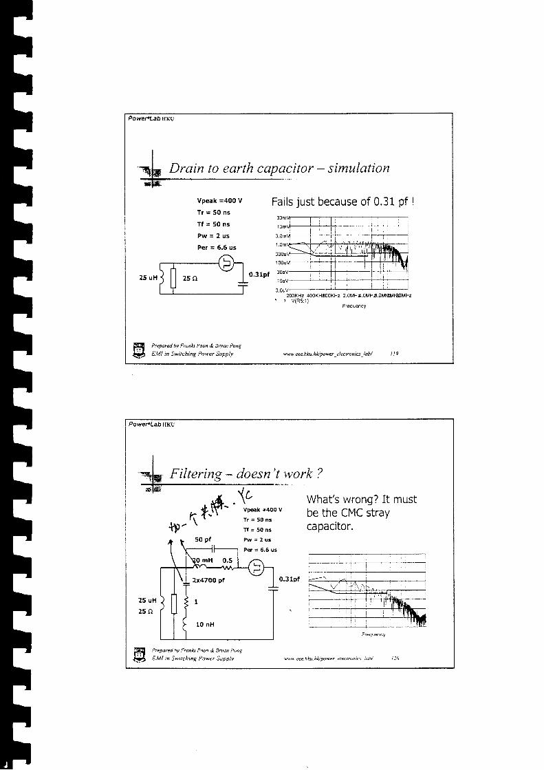
Drain to earth copacitor - simltlation
Vpeak =400 V
T r = 5 0 n s
T f = 5 0 n s
P w = 2 u s
Per = 6.6 us
Preparel hv Franh Poon & Brum Pong
EMI in Switching Power Supply ww. e e e. h ku. h Apower -e I ec t r on ics _l a b/
3.0uV200KHz 400KHE00KHz 2.oMHr.oMHr.oMtlt lftoMHz' r V l R s : 1 )
Power.Lab HKU
Filtering - doesn't work ?
What's wrong? It mustbe the CMC straycapacitor.
0.31pf
25 uH
2 5 n
Prepared hv Franki Poon & Brvan Pong
El,ll in Swttching Power Supolv
T r = 5 0 n s
T f = 5 0 n s
P w = 2 u s
Ptr = 6.6 us
-Lvu ee. n ku. nUpowe | _( I c c I r,,n i..\ _: ahl l : 0

PoweFLabHKU
What's wrong? Bewareof the LISN impedance
25 uH
25f i
Prepored hv Franki Poon & Bd@ pong
EMI in Switching Power Supply
Filtering - parasitics not crucial
I"-qh Filtering - right filter design fl' " Ot' W''
f;H ,h&boNE I50 pf pw: 2 us 4 ' I -
Power4Lab HKU
25 uH
25r l
2x47OO pt
1
1O nH

PowefLab HKU
Don't always blame theparasitic elements
5 0 0 p f P w = 2 u s
0.3lPf rlot
Jt( t . t0t t t0rt i l - tI t i l ! : : l
ww. ee e - h ku. h li powe r _e I e c t r o n tu _! ab/
{I i sl .!r . l f, ir
Prepared bv Fran*i Poon & Bruun Pong
EMI in Switching Power Supply
2x47OO pf
10 nH
Power"LabHKu
h.rtrd 5 p f
Vp€ak =aoo V
T r = 5 0 i l s
T f = 5 0 n s
P w = 2 u s
A very small fi lter canfilter out the noise !!
Per = 6.6 us
0.31pf r l
25 uH
25r l
Prepared bv Franh Poon,i tsnon Pons
El"ll in Swttchmg P.\'er iuDpl| v*w eee hku hltloower clcctronrc: iah/
Filtering - how small it can be ?
2x22OO
1

PowepLabilKu
I=tk Filtering - simplified view-
r) ) i l +-l- r H t t
Prepored bv Franki Poon & Bryu pong
EMI in S\9itching Power Supply ww eee. h ku. h lUpowr e I cctrcn ics lab/
a . n i l
Power"Lab HKu
P.eparetl bv Fronki Poon & Enan pow
E'Vl rn S*.itchinq Power Suoplv
During bridge conductionperiod Tcon
ID
Filtering - get back to the reql circuit , i l i ' l *\ - t
.1\
'avu Lee.nku hlonrwtr,.4cctrrnt6 ab/

Powel.Lab HKU
During bridge conductionperiod Tcon
Prepared bv Franki Poon & 9ryu Pong
EMI in Switching Power Supply ww. ee e. h ku. h l<./ powe r -e I e c t ro n i6 -l a b/
Filtering - get back to the real cirait
Practical Look
PowereLab HKU
Filtering - are the two practical circuiteguivalent ?
During bridge non-conductionDeriod t * Tcon
P-eoarcd hv frunti Poon & Bnun ?ont:
E,llt in Swichinq Power Supoiv
Practical Look

Po$/er.Lab HKU
I'qf* Two dffirent fi lters - go to their equivalence- t *
r--r-^-tFa$-l t l + - rr ? | T
During bridge non-conductionperiod t ;e Tcon
rr*'l-€4 -ALrtJ l l + r ' r -, / t l I
I T I TPrepored bv Franki Poon & Bwan Pong
EMI in Swttching Power Supply ww. e e e. h ku. h l</ powe r _e I ec tro n iu -l a b/
Power.Lab ilKu
2 pl -..,r__r*,.\.\_rrF( = )-_.r\ f ' t | \ 7 I< t t r - |/ t t I +I t / l - T '
Not bad during non-conduction Deriod
,,2 ffr F
Cy: ; i : r l j
l0lir lilil :.ill il : r, l:x, iift
L"namJ hv Fran*t P^un.\ 8^'tn P,'ng
E.lll in Switchinq Pow.er Supoiv "w' eee hku.hlspower _clectronics,!ait/ | )0

PoweraLab HKv
z pf ./__--.\A-_lr_J i If7_
__,1_\f1< i l r I/ l l T - - r -i T I T
Better during non-conduction period
:0 ! .1 S( l i y r r : { l . t r a . rc r : :$ : : f ,nl ; r l i : 1 1
Prepred hv Franki Poon & Bryan Pong
EMI in Switching Power Supplv ww. eee. h ku. h Vpo wer _e I ec t ro n i 6 _i a h/
Powel'Lab ltKU
7iI'tn' 'L"n' (ftfu
t filters - Itft and right
High Z loop High Z loop High Z loop
l r : r : l i l i i i ' r . l l : , 1 r . t i r : { l JC/ r r ' l i , l ) t1 , f l . t ! t l r ;u r , : l r r
wwweee-hku.hLJoower leclronrc! ldh/ ll:
fi ;,-'uo,"u nu ,-,r, ,ou, ,ir'U*un ,*rI# t.ttt tn Snilcning Power Supptt

Power.Lab HKU
Invisible path - Secondary to earthcapacitor
Prepared bv Franki Poon & Bryan Pong
EMI in S\|itching Power Supply ww. eee. h ku h Apo'9cr _cl ec r ron ts _lah/ 1 3 3
LISN t- rT
:t-E
Power.LabHKu
Sec. to earth capacitor - circuit model
Prepnred bv Franki Poon & Enan l,ong
EMI in Switchinz Power Supplv
LISI{ 'FIT I{E
I F
,re\+ cee. hku. n lu power _el ec tn tn ru -l ab/ ! i 4

Power.Lab HKU
capacitor - how big ?
C = 0.085A/d pft C* | _ [-----7 O.r5cr'
) --tt-( .-t"7 /7 + C**=53pt/
" \
- / //- i
r = 7.5cm
Cspnere= 4to,0885rpf
CsE : 1.67 pf
Prepared bv Franki Poon & Brym Pong
EMI in Switching Power Supply ww.eee.hku-hlawwer electroniu lab/
PoweFlab HKU
VpEak =4O0 V
T r = 5 0 n s
T f = 5 0 n s
P w = 2 u s
Per = 6,6 us
- rare noise
Greatly exceeds limit -usually come across inbad designs.
Preparpd hv Frann Poon & gruun .\'nt
EtVI in Switchins Power Suppiv *ww eee. hku.hlt power jlectronrcs ,iab/
capGCitor
t i 6

Power.Lab HKU
Still exceeds limit evenafter filter is added.
Prepored bv Franki Poon & Bom Pong
EMI in Switching Power Supply ww.eee.hku.hApower-electroni6_!ab/ 137
to earth capacitor - with filter
Vpeak =400 V
T r = 5 0 n s
T f = $ g n "
P w = 2 u s
Per = 5.6 us5
2x22OO pt
2 5 u H 1
2 5 n
10 nH
PowefLab$Ku
Sec. to earth capacitor - Pri.Capacitor
To Sec.
H#
The primary to secondary capacitor can by pass,Ih 5,,f; p)fr ,g,S15g1j",gen e rated f ro m th e p r i m a ry s i d e.E,Vl in $witchinq Power Supolv avw Lee.hku.hvpowar -electrontu-loh/ l J8

Power.Lab fiKU
-\ Pri. To Sec. Capacitor - circuit model
Provide a lowimpedance path toshunt or by passthe current flowingto earth
Or you caninterpreter Cps asdividing down thenoise voltage
Prepared by Franfi Pan & Bryon Pong
EMI in Switching Power Suppiy ww.eee.hku. hL/power -electronig -iab/ | J9
PoweFLabHKu
To Sec. Capacitor - save power
Much better soiutionas no eKra Dowerlosses is produced.
-rir xtr . tl :;$ :rli
Vpeak =4OO VT r = 5 0 n sT f = 5 0 n sP w = 2 u s
Per = 6,5 us
2x22OO pt
2 5 u H 1
25r l
10 nH
fi P."ooreu hv F.anki P.o, & Bwon p,ns
# t,Vt in Swilching Power Supplv svw. tee.hku.hvpo*er _electrontcs -!ab/ i l0

Power.LabHKU
To Sec. Capacitor - drawback
HI{ttPrepareel by Franki Pmn & Brynn Pong
EMI in Switching Power Supplv w w. ee e. h ku. h fu pow er -e I ec I ro n i c5 -l ab/
Increase leakage current !Capacitance is limited.
PoweFlab ITKU
I
: . . - . . . . . . . . . , . . . . . . . . . . . .
Any point on this sideprovides by pass effect
Q! C.vtt tn Swtrchrnq Power Supp} .t ttw,: ee i ku. n ll lnwer,. i cclro n tc-t.�i.th/
(d,h c''xf
Wfa'n:u't

How to split the straycaDacitor ?
Sec. to earth capacitor - by pass inside ?
Fi{stPrepared by Franki Poon & Boan Pong
EMI in Switching Power Supply ww. eee. h ku. h Upowe r -e I ec to n is _l abt
Power.Lab rrKU
I
I
i
capacitor - F.5 physics
I-T-
T
Powel.LabHKu
III
-T-II
ie\. lee hku hlapo\'er tlectntntcs ldh/
H ,,"uur"u ou rrankt Poon <i Stuon pong
E* EMI ,n \wilchmq Power Suoplv

Power.LabHKu
to earth capqcitor - qdd one more plate
Fil
ffi Preparerl bv Franki Poon & Bruon Pong
5., EMI i, S*ttching Power Supplv ww.eee.hku.hVpower _electrontq -lab/ 1 15
PoweFlab HKU
to earth capacitor - better way to by poss
ffi ."<oared hv F,un* Poon & Brydn P,)n\
&) e .Ut m Swrtchuq Power Supolv 'urtw. cee hku. nlv power lleclrontcs idb/

PowePLabHKU
Preparcd bv Franki Poon & Bryan Pong
EMI in Switching Power Supply w w. eee. h ku. h la power _e ! ec I ro n rcs _l aol
PoweFlab HKU
capacitor - another noise source
Fi
HSecondary winding alsoact as a noise source
Prt'pared hv Franki Poon & Bryon !)ong
EtVl in Swrrchins Power Suppiv
LISN +f II +[
r : I^�\
v \ !wcee.hku.hvDo\9er , i l cc t ron tcs 'dh / l l l
Power.Lab lrKU
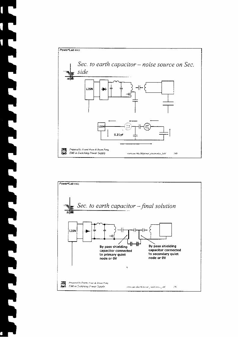
Sec. to eorth capacitor - noise source on Sec.side
Preparcd bv Franki Poon & Bryu Pong
EMI in Switching Power Supply w\e. e e e. h k u. h l,Jpo \9 e r _e I e c t r o n i q _l a b/
Power.Lab HKU
capncitor - final solution
By pass shielding By pass shieldingcapacitor connectedto secondary quietnode or 0V
capacitor connectedto primary quietnode or 0V
l'reparet! hv Franki Putn & Bruan Ponc
EMI in Sttitching Power Supniv $rw cee rku hl!po\|cr :lectrann:s obt

Powe-LabHKu
B1t pass or simply short circuit
By pass any noisegoing r ight
By pass anY noisegoing left
Prepared by Franki Poon & Bryan Pong
EW in Swilching Power SUPPIY ww. eee nku. hfu power -e lec rrunit -[abl
Power'Lab HKU
Iqlk Don't forget the leakage capacitors
ffi P,eorct ht F-nkt P't,tn & Bnon l','ng
{t f f . t t l ,n Sui lchng Po*er SuPPlt sr w eee. h ku. h lJ Do\eer I I ec I n ) n tcs -i ab/

Shielding, by pass or short circuit 7
Fiqla
Does it "shi€ild" all the noisegoing out ? qtuQ'ffifu:
Prepared hy Franki Poon & Bryan Pong
EMI in Switching Power Supply wvw.eee.hku.hly'power_electroniu_lob/ t5J
Pawer.Lab HKU
/i\- 1 J F -
\-l __.] L_l l
,4hp'il--
Large Metal
Prqared hv Frunki Poon & Erran l>onc
EMI in S*itchinq i)ower \upplv
i.-:-_)
r i"r--J\,1JL- --ll--r L "
i l l ;--:E::--
'"*w eee hltu.hlloower':leorontcs loht
Rer-ision again - I

Power.Lab HKU
rwv It #
I -
TLarge Metal
ITI
AvI
Prepared bv Fronki Poon & Bruan Pong
E'Vl in Switching Power Supply
-.rA--rLJL[�-l\ 7 r r L - - - - : j
'*w. eee. h k u. h lo power -cl ec! ron t 6 _lah/
Revision again - 2
Power.LabHKU
II
I
4W Don't float the metal plate/:__
Nc l / - .| / h l
h'Ae \7 -JF
Larse Metar -'1F
--:-i W\'tti tr - lt.I.1.'r..I-"l.]--ffi.I-
r-lt l
\Z| ,-., lou , r:::r,
-lv q : ! - J ! J F l " l I
\ i / " ' _ :
HH
'.Tarcd hv Frdnh Pmn .J Bnun P ny
# t.Ut .n S*ttcntnq I 'tuer Supplv 'avw cee hku.hApower _4lcctronics _lah/ i 5 6
T

Power.Lab HKU
By pass all thenoise currentback to 0V
| ^ 11 [g:Zt-; -l
rhevictimwourdovL{:}- itr -ll- |
" j see any noise\-./ | | Curlent IIOW ln
--]"]..].]Ttr].ffifEE-
The victim wouldonly see the 0Vof the noisesource
ww.eee.hku.hk/power electroniu lab/
By pass and short circuit
Prepared bv Franki Poon & Bftan Pong
EMI in Switching Power Supply
POweFLabHKu
-aaShielding -Usually come acrosscharacteristic impedance,attenuation, refl ectionlosses
The Truth is -Plane wave propagation, or noise source is located at a far distancefrom the shield.
Prepared hv Frotki Poon & Eoun Pong
E,lll i.n Switching Power Supplv
Wait a minute
N|| eee.hku-hupower electronrcs .'uot i58

Power.LabHKU
Sttll Ltse by pass and short circuit concept
r l l w V 1
.:I
T c'arf
If far enough,C*17)) C*o1"
\+ ) 0 -tF
Prepared bv Franki Poon & Bdan Pong
EMI in Switching Power Supplv w\|. eee. h ku. hk/lb'9er _e I ec I ro n i6 -l a b/
€-
Power.LabHKu
Prepored bv Franki Poon & Bnan h)nr
Elvll in Switchins Power Supol.v '"ww eee.hku.hk/powcr jlectrontcs,lab/ I 60
Short summary. Lump element circuit is possible to simulate EMi
behavior,' Parasitic elements is not enough to explain all
cases. (More concept will be introduced.). So call electric field shielding rnust be
terminated one end to a quiet node or 0V of thenoise source. NO FLOATING I
. So call electric field shielding is a kind of bypass/ shunt or Sbcd-Cjrcuit equivalent in a lumpelement modell
H,*

Power.Lab t|KU
Prepared bv Franki Poon & Bnaa Pong
EMI in Switching Power Supply ww.eee.hku.hUpowerelectrcni t lab/ 16l
iil|]fi qufl$t10fi
H
PoweTLaO HKU
Duringperiod
Prcpaftd hv F,anki Poon & Snun Pong
E,Vl in Switching Power Supoiv
bridg€ conductiont = Tcon
:vtvw cca nku hllpwer t:leoronrc-t labt
Input terminal - conduction period
! 6 2

Power.Lab ItKU
During Oiiage non-conductionperiod t * ' [con
Prepared by Franki Poon & Bryan Pong
EMI in Swrtching Power Supply
Input terminal - non-conduction period
Power.Lab HKU
Input terminal - coupling capacitor
=0 .01 cm I
0 .1 cm
Inputtrace
oo
H ' - . .Dar (u . t f ' r D tk t i> ,Dn. i Bn 'un t "ns
-$ r . l l l tn " * i t ch tnq Pcwer Supp l . t ' 'mvw. eec. h ku. h lv power -: i 4 | rt ) n tc i _ db/

IIIIIIIIItIIIIIIIIIII
Power.Lab HKU
Input terminal - coupling capacitor value
" lrace lrace -
0.0885a(e , + l ) / :l 0 - r 4
z (
/ t n ( - )' W + t '
5 1 = 5 c m
52 = 5.4 cm
W = 0 , 1 c m
t = 0 .01 cm
E r = 4
Prepare<l bv Franki Poon & Bryan Pong
EMI in Swtching Power Supply w. eee. h ku. h Apowe r _e I ec r ro n t u _l a bi
0.0056 pf
PowefLabilKu
:
0.0055 pf
Vpeak =4OO vT r = 5 0 n sT f = 5 0 n s
s o a / l50uH x2
P w = 2 u sPtr = 6.6 us
:ww eee. h ku. hA power ! | ectron tLs - oh/
terminal - simulation
0.0055 pf
ffi !',cpar.tt hv Fnnti "oon & 8^an Poa\:
Ss+} f j . !11 n Swrchtnq Power Suoptv t 6 6

IIL .
[ -
IIIIIIIIIIIIIIIIItr
PoweFLab HKU
Input terminal - imbalance impedance
Prepared by Franki Poon & Bman Pong
EW in Switching Power Supply qw\| cec. hku. hvpo\'er _e I ec t ron er -l ab/
Powe-LabuKu
Input imbalanc e impedance- simulation
Limit Exceeded !! .,; t - t t n - u h v i . ; t t h / > . " n < i 3 r . n . ' o y
E,Vl i.n Swrtching Power Supolv
0.0055 pf
100 uH 0.5 Q 0 '
5O uH 0 .2Q
Power.Lab HKU
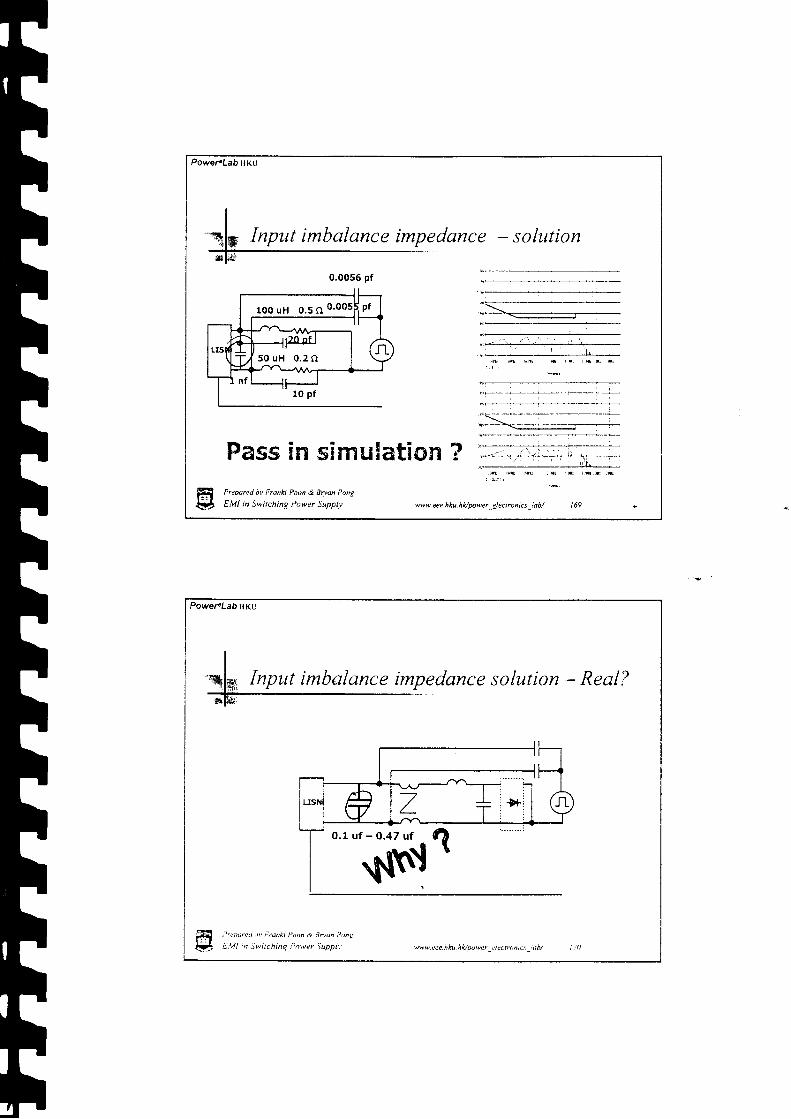
Input imbalance impedance - sohttion
Pass in s!ffrulation ?Prepmred by Franki Poon & Bryan Pong
EMI in Switching Power Supply ww.eee.hku.hVpowerAecrronics-lab/ 169
0,0055 pf
1OO uH 0.5 n 0.005
50 uH 0 .2O
Power.Lab HKU
Input imbalance impedance solution - Real?
w|| cee hku hfupo\|er zlectrontc\ lttb/ i1A
0.1 uf - Q.47 ut

tItITIIIIttIIttI
Powef Lab Hriu
-T3fr Input imbalance impedance solutiorl -_hence
'f'P'th t-' b l4t3q2oo'
@\{fur
ff i ,ta",,u,'v;.,nn Po,n & Btuun p,)nt
V E.ll l .n j*uchtnq Pcwer Suppiv 'w* .cee.hhu.n lonwer : tec t ron tcs , th r
0.1 uf - O.47 uf
Power'Lab lrNU
*i= Dont forget* l -
llllis,'.*''U l*J Magnetic Noisevoltage
: / \l--\ -,^/-=-
-'- \,/Vu pi"k uo
EMI in Switching Power Supply ww.eee.hku.hk/power-elrctronis_lab/ f 7t
I I l" 1r,"o,.,. o.,o | |7 t + i + r N o i s e
& ;.-I--&H tst --r/ ----,/!0"--Scffirrri eoon & Bruu Pong
vr pitk up

PowereLab vKU
Input imbalance impedance - bad CMC
A filter is formed by the leakage inductance ofthe CMC to provide extra attenuation cln thenoise picked up by CMC
Prepared bv Franki Poon & Bnan Ponq
EW in Switchinq Power Supply twteeehku.hk/power_electronics_lab/ l7J
0.1 uf - O,47 uf
Power.LabilKu
Input again - is everything fine?The large input X-capacitorprovides a final lowimpedance loop with theLISN. Magnetic couple wil lcontribute to noise pick upby the LISN
Prepared bv Fruilki Poon d 8^vn ['')n\
eMl in Swtchinq Power Suopil' .6t9' tec.hku.hlrlpo*er -lectrontct lttb/

PowereLab HKU
1 c m
5 c m
2 c m
2 c m
- - l -
-Ll-
f
f:Z^| . . .1 { . ' \ y
ffi Preparetl bv Franki Poon & Boan Pong
V EM! n Switching Power Supply ww.eee.hku. hupower electront6 lab/
Input again - mutual inductance
Power'Lab HKU
I l cm
I
Ioop mutual inductance
W'= 7 cm
W = 5 c m
L = 2 c m
Ltine_top = 0.73 nH
Ll' * W'L I ir, - t n,, p = 0'00: I ( ln(--------- ) u H'
W'= 7 cm
W = 7 c m
L = 2 c m
Ltinc_toop = 0,53 nH
T -Lline_loop_Eqv. -
,''repared hv Frunki Poon,i 9ryan Pong
E.lll in Swtchrnq Power Suoolv
O.2 nH
t 7 6
Approximated line to
M eee- h ku. h *! powe r _el ec tron rcs -i tb/

Prepared bv Franki Poon & Bman Pong
EMI in Switching Power Supply
fs = 150 kHz
uww. eee. h ku. h fu power _e I ec t ro n i u _l ab/
Input loop noise - example
Power'Lab HKU
LIS!I I AVi 'F
{E
TI
Ip€ak =25AI in i =15 AT r = 5 0 n sT f = 5 0 n sP w = 2 u s
Exceed limit becauseof small input loop.
Input loop noise - magnetic tnduction
0.1 ufPer = 5.5 us
Power.Lab HKU
a\v||- eee. hku. h Apo\|er _c I ectron rcs ! ob/
ffi ,'r"oareu hv Frank P'nn 3 Brydn p.nq
t j EVI inS*ttchrng Power Suoolv

r|IIIh
PoweFLabHKu
Prepared bv Frunki Poon & Boan Pong
e Ml in Switchinq Power Supplv '^ew eee.hku ie Dower _ 1ccnonrcs, ahl
Converter to
Power.Lab ilKU
Zvo-rt
Prepared bv Franki Prcn & Bman Pong
EMI in Switching Power Supply ww. eee h ku hupower _c I cc tron i6 _l abi t79
Other noise loop ?

iI
I
IIThtrhhhhtttttIIr|r|r|
PoweraLabHKu
Loop - capacitor
+
Let the total surfacearea of the wholeconverter is equal to asphere with equivalentradius r
r= 5cm
As the self capacitanceof a sphere of rcm
Croh"r.=4x0.0885rpf
The equivalent drainself capacitance is
Cdrrio = 5,5 pf
Prepared by Franki P@n & Bryu Pong
EMI in Switching Power Supply \ww.eee-hku.hupo'|er -electront6 _lab/ t ll I
Converter
Powe.LabuKU
- Qpical value
r = 1 c m
R = 2 c m'V ,,r" -,u,,,
R i R r ._ - / { _ ) - _ t _ ) -
r 0 0 ! ' r o o ' ' 1 0 0 '
The mutual inductance is
Z,^.-rjo!. =3,3 nH
fr P.'parel hv Flnk Pd,,a & Bnan P,ns
l# E.lll n Swtchtnq Power Suoplv
Converter earth Loop
, rw , :pe .hku .hLouvc , le t ! ron ic t ieb /

Converter to eartlt Loop - resonate loop
Fh
ELTF
h
EhIt!I
Prepared ov Frunki Poon & qruan P'tng
ELll in Switching Power -iupply, ww eee.hku.hlopower .4ectronrcs ,ab/
Converter to earth Loop - raw noise
25A still can'tfail it!
Be careful,,***,r*8"3.[[y;[oseEMI in Swilching Power Supplv
!w\9. eee. h ku. h Apowe r _e I ec I ro n i 6 _! a b/
Ip€ak = 25AI in i =15 AT r = 5 0 n sT f = 5 0 n sP w = 2 u sPs = 6,6 qs
300 uA fail it by30 dB
Fail, much worse :rii r/r !
than the 25A case !

L1 Lz c r lF * "7
,7 t , r6
',|tft'E '
[* t- \ IE'h "
r *
ttItIIthhtrhhhtrTrIII
Power.LabHKu
sto'\ l l i; i.: '
L 3.3 nH 11
22O pt
00 nH vn
vp€ak =400 VT r = 5 0 n sT f = 5 0 n sP w = 2 u s
t ,
Atrnductor only di ift theresonate point.
Prepared hv Franki Poon & Boan Pong
EMI in Switchine Power Supplv
gt't('Nw. eee. h ku. h Apo w e r _e I ec t r o n i6 -! a b/ Iil5
(
Resonate loop - CMC c
Power.Lab HKU
Resistor reflectingcoae loss€s
Resistor reflecting Resistor reflectingskin / proximity dc winding losseslosses
Frequencydependence
Frequencydependence
Frequencydependence &windingstructure
Wire sizedependence
Remember this ?Prcpareci hy Fnnkr Paon & ?rudn Ptn{
E,Vl in Swtching Power Suppiv
Resonate loop - RES/STOR
'ttvw ece.hltu.hlvpuwer clettft)nics ub/

PowefLab ilKU
Resonate loop - increase resistance
1OO uH +10l / L p f
Unfortunately, notmuch better.
Prepare<l bv Franki Poon & Bryan Pong
EiVI in Swilching Power Supply www. e e e. h k u. h Apower _e I ec t ro n t cs.�i a b /
22O pt
Vp€ak =400 VT r = 5 0 n sT f = 5 0 n sP w = 2 u s
Power.Lab HKU
Increasing resistance - at. ,
- ' . r | |tne rtgnt place
Much better, but how ?
! i i ! lr;r ' i ir, :..!t j f^lr . Llr ::!.1 j$' : :
!'repared bv Fronn Poon d Bnon Pony
E,lll Ln Swirchnq Power Supplv
22O pf
Vpsk =4O0 VT r = 5 0 n sT f = 5 0 n sP w = 2 u s
tww eee.hku.hloDo||er riectrontct iab/ i88
hIInI

'r{ d"' Pt LS
PowefLab HKU
Prepared hv franki Poon & Bryan pong
EMI in Switching Power Supply
II
p c n
\r- a
ww. eee. h ku. hHDower e I ecrrcnis labt
Increasing resistance - lossy ferrite
22o pt
i',tuarea hv irukt Pnon & Boun l,on\
E,l/l in Switchins Power Supolv
Power.Lab tlKU
Ferrite beads
'ww.eee hku.hh,power cledronrcs lob/

FtIhhtthhhhhhtIII-t
IIIr|I
PowePLab HKt)
Invisible loop - inside xformer
Xformer is tightly packed and has large stray capacitor tointroduce many loops inside.
Prepared bv Franki Poon & Boan Pong
EMI in Switching Power Supply ww. eee. hku. hApower -e I ec r ron rcs -l ab/
PoweFLabrrKU
I"qk Short summary
. Capacitive coupling to input terminal causes EMI.
. Solutions for capacitive coupling lead to moremagnetic coupling effect.
. The whole convefter to earth has a large capacitor.
. Magnetic coupling causes EMI due to the loop formby the convefter to earth capacitor.
,j;if, Resonance causes unexpected EMI level.. Damping/not inductor, is the solution for resonance.
+6-tv ttad . 4{ r;l r Q fit g-'? I"4 t t ld--'
ffi P-eparet hv Ftunxt P.on d 7tudn P,,n\
i f i S,Vt n Swilchng Pnwer Supplv *rw.eee.hku-nlapoler_t lectrcntcs_labt i92

I|I
t
III
Power.LabfiKU
finy $mqtle$tiun?FH{!a
Prepare<l hv Franki Poon & 9ryil Pong
EMI in Switching Power Supply ww.eee.hku. hvpowcr _electronia _lab/ 193
Power.LabAKu
How does EMI come out?Contacted -
can be understood
through circuit diagram
Non-Contacted -
Mufual invisiblecapacitor & Mufualinvisible inductor
avw ree hku hioAner 'lecrntnrc.t !ah, ,94

httIIIIrll
PowePLab HKU
Preporerl bv Franh Poon & Bnon Pong
EMI in Switching Power Supply ww eee. h ku. hApower -eI ecton iu _!ab/
V & I O n l y
Power.Lab HKU
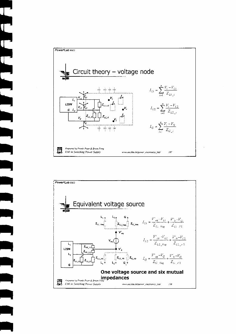
Only LISN terminals voltage are
L1
LISN
G L ,
l,^,l v , ) I
f f i .I I,:'' A
-'tI z.
r No matter howcomplicated a circuit,EMI are voltagemeasuremenB, VL,r",and VLine2, across LISNterminals.
. Vlinet = VL1-VG
. Vtine2 = VL2 - VG
r Is there a simple wayto look at it?
ffi P'eutr.a hv F,an<t i','on & 3nun Ponq
l!|. t.Vtt tn S\rilcnmq, Pnwer Supph' *vw.eee.hku-hl</powerelectronrcs lab/ 196
t*rhhhhhtttIIIFI
tttIIIIt
PoweFLabHKU
r - S / , ' Y l , ll t t - / /
t t f l f l
l . ^ = T Y , - Y L :' L t / -
, L t 1 ,t = l
' t f / f ,
r - Y Y i - ' Gr c - /" ? 2 . ,
Pr.psred hv Franki Poon & Bmm Ponu
EMI in Switching Power Supply ww.eee.hku. hUpawer _electroniu -lab/ 197
vL1
LTSN
G L z
\tV* V'u
t n o u " " i
\Ir
PowefLabHKu
Zn-u-
r / ' V t / l,
' e q - ' L l r l - Y L lr / t = -
7 7L L l veq - L l v t )
. v ' ; o - v r = v , u _ v t :f - ' t ' -
ZL7 , "0 Zra , ,
a' , i ' : - : t , , V'"r-VO V',)-VCu0,., i .Zt:-uo j . i zc-uo t . = -
L, i Lr i c.; "
26 _req Zc _r,t
One voltage source and six mutual.impedances
i'rypareol hv Funkt Poon ,7 Bnan Ponr
EMI in Switching Power Supplv .ww.eee.hku.hk/power clectrcnrcs !ob/ t98

PoweraLab tlKU
vr-rr-r, t , / - \ - r z' . " 1 _ L l . L : -
L t r L . r l - l . l _ L : , i
m
t r ' - \ - r z' V _ L l - G -
L . ' i u . U _ L l . G _ r
m
t . / - \ - l z' . u - G -
/ r r i L , v _ G _ i
f. . . - - t
i it . . ' . . :
Prepare<l bv Franki Poon & Bnoa Pong
EMI in Switching Power Supply w\9. eee hku. hupower -electroni6 _lab/
Power.Lab ltKU
source
l / - I 7' v . L t - L :
- t . q . \ t L t . L 2 - t e q
' , V - C - r e q L . V G l e q
\; t - "Ddr (d rv Fr ' i l t k t P . "n , i Bnan P, tny
E,Vl in Switchtnq Power Suopiv
' . V L l G - l e o L \ 4 L l G l e o
One current source and threemutual impedance
ww.eee.hku.hk/powerelectrontcsiab/ :ll0
Equivalent current
tI-1'
!-
E

Powet LabHKv
Total 9 eguivalent mutual coupling impedances
1 equivalent voltage source
1 equivalent current source
Prepwred bv Franki Poon & Bnon Pong
EMI in Switching Power Supply www. eee.hku. hUpower _electroni* -lab/ 20 I
PowefLabHKu
0%-utn'Hot switchingnode to eafthequivalentcapacitor
HF'
Prepared bv Frcnki i>oon & Bn-an Pong
EMI in Switchinq Power Supplv
Physical meaning
,nw. e e e. h ku. h kl pow er _e l ec t ro n r cs.�l ab/

hhhIIhIIIII
Power.Lab HKU
Crr-r.o&Ctz-ves-
Hot switching nodeto input tracesrepresented byequivalentcapacitors
Prepared hv Franki Prnn & Bryan Pong
EMI in Switching Power Supply ww. eee. h ku. h lo power _e I ecrrun tcs _la bt
Power.Lab fiKU
LVo & Cr'-no
Preparetl nv Franki Poon d Bnan Pong
E,Vl in S\litchinq Power Suopiy
Ctt-no&Ctr-vo-
0V node to inputtraces haveequivalentcapacitors
e
Absorbed in theinput impedance.
'ww eee.hku-hL/g)wer -Llectronrcs _,an/ :01
Physical meaning - Ct

t;
t;
;
;
tr|tI|ttttttttttt
Power"Lab tr(u
Ce-ro-
Converterto eafthequivalentcapacitor
Prepared bv Franki Pooh & Bnan Pong
EMI in Swrtchinq Power Supplv twtr - e e e- h ku - h Apow e r _e I ect r o n ics _l a b t'
Power.Lab ilKu
aLttt_tl_Lz_req-
Input l ines loopmutual inductiveimpedance
i ) r "pare , l t v F . .nx t i ' , rn * . lnan P n t
E,lll in Switchinq I'cwer Suoplv t\'\r v r ec. il tu. n B Do |9er -!l ectro n Lct _idb/

V,vr - S r zC
- / J ' t L , \ l _ G _ i
7L M_G_req
Earth toconverter loopmutual inductiveimpedance
Prepared hv Fraaki Poon & Bryon Pong
EMI in Switching Power Supply ww. eee. h ku. h Apo w e r -e I ec r ro n r c s -l a b/
Power'LaD HKU
I+r+rtI
I
tIIttr|ttr|tt
' \ l - L l i - t L q L . l l _ L l , , i l e q Zr-tt-n-req-
Cross section ofLine 1, l ine 2 andeafth loop mutualinductiveimpedance
Preparecl bv Franki Poon & ]ruon Pong
E.Vl in Switching Power Suoplv
PoweFLab HKU
wttw. eee. h ku. hlo powe r -.i ec Iron ics _l db/

Power.Lab ilKu
vp = 4oovtr = 75O ns
t f=20ns
D = 0 . 2
Fs = 75O kHz U = ISO ns
ffi PrepareJ hv Franki Paon & Bdok Ponq
$f, t.Ut ,, Switchinq Ptwer Supplv
fs = 15O kHz
twv. eee. h ku. h Apower -e I ec tron iu -lab/
Overall simulation
O = 0 . 2 n s
PoweraLab HKU
4 c m II o.1 cm
I l-TIr I n
l l\z
) o'rr.^
420.085I - - n f-sphere-
| YJ
Prepared hv Franki I'oon & Enun Pong
E,Vl m Svitchtng Power Supplv
Cn_ruo = 0,2 pf'qvwcee.hku.nhpower-"l""rror,r.r-tnllrt 2t0

Powel.Lab HKU
Realistic palameter - Crr_vuq & Cu_r",t = 0,01 cm
+
0 .1 cm
oo
5 c m
0.4 cm
C trace rroce0,0885a(e . + i ) /2
zSl l n (
- - )
W + t '
l o - ' '
5 1 = 5 c m
52 = 5.4 cm
W = 0 . 1 c m
t = 0,01 cm
ef = 4
Crr_rn = 0.0056 pf
Crr_r* = 0.0055 pfi>repared bv Franki Poon & Soan Pong
EMI in Swttching Power Supplv wts.eee.hku.hApower_electonrq_lab/ 2ll
Powe,-Lab vKU
Errl@ parameter - Cr, ,o & Cr, ,o
Absorbed ininputimpedance.
708 uH O.tO
H , ' - 'o"r" , l n fntnxi Poon & dn,n p,,nt
t7r-h f:.Ul .n Swtrchrng P,rwer Suporv ,ww eee. hku.hltpower,:iectrenlcr l.b/
IIr|

PoweFLabHKU
Measured as
Co_no = 6 pf
Prepared hv Franki Poon & Bpan pong
EMI in Switchine Power Suppll, ww.eeehku.hUpower electrunis lab/ 2l l
Power"Lab HKu
r = 2 c m
R -- 7.9 cm
The mutual inductance is
Zn-c-r.q =77 nHfi
..-ea,.u ;v i,"^x, il,,i ';'j;",
,,.,,r$tl E,l// tn Swttchnq PawaT \ypoi, ,qew.cee.hku_nttoower elerronrcs lab/
r|
Power.Lab HKU
As the input loops are small and havingquite a high input impedance, hence forsimplicity,
Just set
Zr-rr-G-r.q = o
7 - 0aM_L2_G_feg - |
Prepcred hv Ftunki Poon & Bmm Pong
EMI in Switching Power Supply ww. eee. h ku. h A power -e I e c tr on iu -l ab/
PowefLabHKu
I'rk PSPICE Simulation
r $ : 1 . / { r o o 5 . o
i
/{'w
r b ).*v*.eee.hku.hAytwer clec,ronics iab/
f f i , ' r "ooret . \v ; . ,nxi . ' r tn & \ryun?ong
IJb tUt in iwilchnq l'ower Suoplv
IIIII

PowereLab UKU
Simulation & Measured Results -
ii,rril'frL,,,,1 *J'
tily6,ttiu'"ff* w-*6r'�{{a+ 4+"errp"e'- r'l
Line 1 measured result 51 open Line 2 measured result 51 open
Line 1 simulated result 51 open Line 2 simulated result 51 open
Prepared bv Franki Poon & Bryan Pong
E,VI in Switching Power Supplv w\r.eee.hku.hl4po*er-electronics-iab/ :17
51 open
PowefLab fiKU
Line 1 measured result 51 close Line 2 measured result 51 close
Line 1 simulated result S1 close
P,epared hy Frun*i Poon & Sdun Ponq
Etlll n jvtching Power gappiy'
Line 2 simulated result 51 close
.ww tee.hku.hloutwer :tectronrc: lab/ I lE
Simulat ion?: 51 closed
tIII

PoweraLab HKU
S1 open - Capacitive coupling only
Resonate behaviorbetween the inputequivalentimpedances
Prepared bv Franki Poon & Btuan Pong
EMI in Switching Power Supply
Line 1 measured result 51 open
ww.eee. hku. hlvytwer -electroncs _{ab/ : I9
Line 1 measured result 51 open
Power"Lab ilKu
51 close - Capacitive & inductive coupling
equivalent impedance-
Resonatebehaviors of thesource loop andmutual inductivecoupling
Line 1 measured result 51 close
f f i Pnpanu hv F,ann Ptnn. i dnon P.nt l
*4 E.Ul m Swtchng I 'o\9er SuDptv *s\9 eee.hku-n*/oo*er electronE\ idb/
Ir|

PowereLab AKU
Prepared hv Fronh Poon & Bn'an Pong
EMI in Swrtching Power Suppl.v
Minimum Coupling Model. A minimum of stx capacitive mutual
coupl ing impedance is concluded.r A minimum of three inductive mutual
coupl ing impedance is concluded.. Complicated EMI waveform can be
simulated by simple lump elementcircuit.
r I t is a minimum model, not maximum. Good for diagnosis purpose.
fT{t" @w.ece.hku.hlupowcr elecrranrcs labt -'-'/
Power.LaD HKU
Hr!'
^l^Sil|)fi nrrc '' 0'u*ur r tllltsll0il i
!'repored bv Frunki Poon & Bnnn i'ong
EMI in Swilchrnq Power Suppi,.' , v tswcee.hku.h t lpower 4ecr ronrcs .ob / )22

Power.LabHKU
Don't let anycurrent flowinto theLISN
ffi P.eoare,l h F,nnkt Poon & Bmun ponq
.t!:t t.t1l in Swuchinq Power Supplv \Nw. eee.hku. hlqpower _e[ecrroniu -lob/ :: ]
-1, Shielding - Purpose
Shield or being shielded
I lock upthe wholeWOrId, HE,h a , . *
i)reparel bv Franki Poon <,) ilruun pont
.i,lll in Swtchinq Power SuDplv ' v rvu eee h l iu .hk l *e r t l cc r r ,n ts lahr

Power"LabHKu
Fi{:?
Prepored bv Fronki Patn & Boon Pong
EMI in Switching Power Supply ^w w. eec. hk u. hkt pot e r _cl eer ron rcr -tab/
L1LISN L2
G
Put a metal enclosure to "shield"
noise from going out - Wrong
PowercLabHKU
I
"1k Shielding - total recall 1*l* tffil- :
tLarge Metal
No electricshield
IT
A(rL)I
Prepored hv Fronki Poon & gruan ?'tn(
E,Vl in Switching Power Supoiv
Actually, increasecoupl ing
-lF--tF "== IH{!? .uww tee.,:tku-nbttowar tlectn)nrcs lobl
hII

Power.Lab HKU
Preporcd b| Frcnki Poon & Bryan Pong
EMI in Switching Power Supply wlw.eee.hku.h lvpower . : lec t ran ics lab / : :7
L1LISN L2
+l l Gt_f
Put a earthed enclosure to "shield"
noise from going out - Wrong
PowercLabHlr(U
*k Shielding - total recatl 2*tr*
An eafthed enclosureactually increases theequivalent hot node toeafth capacitanceCn=*oand increasesnotse.
LISN 2, zvo Lt
f f i P-cpa,eu nv;rank / 'an & 7ruon P.,nt
I ! | , 5.ut 'n Swtchnq Ptwer Sunpn 't'v*' eee.eku.ngc,;wer ricctrlntcs db/
Ir|r|

Shielding
The vict im wouldonly see the 0Vof the noisesource
is all about bypassing or short circuit
ww e e e. h ku. h Hpower _e I ec tro n i 6 -i a b/
h'-V
By pass all thenoise current
back to 0V
Power.Lab HKU
Prepared bv Franki Poon & Bb^.1n Pong
EMI in Switching Power Suoply
IIl-
II
IT -
Ih
I
hh-
tIIrlIIIrIIIIII
Preared bv Franv Poon Li /)n'un Pong
E,V l in Swi tch tnq Power Suop l t ,
PowefLab HKU
L1LISN L2
GThe so cal l "shielding" should short to noise
source 0V to rdturn al l the noise coupling tooutside.
nvw eee.hku.h l tgwer ' i t c r r tn r t ,an t

fftthhhhhbItL-rhhtttttt!I
I
PoweFLab HKU
a[ 0V is the point - Xformer* t *
To secondaryequivalent 0V
I -t-ta-An-- W2
-I _/-t/-Y-Y-\_
To primaryequivalent 0V
To primary To secondaryequivalent 0V eguivalent 0V
Prepared hv Franki Poon & Bryan Pong
EMI in Switchine Power Supplv ww- ee e. h ku. h lr/ pow e r _e I ec t r on i u _l a bt
PoweraLab flKu
I
-lu 0V is the point - MOSFET
i, r l . . l . ! l . l . l
t . l t i l . . . 4; ;: a: -n . rdn l_ inp ! t
. Cra-tnprt
! . . . . . . . . . . . . . . . . . . . . . . . ::
Crct-ncaunr I
l1-vpar"u tr Frunn P nn .t Bn an l' ,ns
EMI in Swi tch tnq Power Suoo ly , @\ | ece .hku .h fu ! )wer lec th 'n rc , rn ,

r|IIII
hh
PoweraLab HKU
Grounded Case ?
Prepare<l by Fronki Poon & Bn'an Ponc
EMI in Swilching Power Supply avw ze e. h ku. h lo powe | _e I ec I rDn t6 ., ab/
L1LISN L2
G
The "shielding" to 0V wire is replaced by largecapacitor to provide ac short circuit effect.Then the case can be shorted to earth forsafety purpose.
Powe.LabHKU
Poor grounding wire or parasit ic impedance ofthe grounding capacitor force the couplingcurrent f low back to G terminal of LISN.
l'r?pored hv Fronii Poon & Boun i'ong
E,lll in Switchinq Power Supglv '""w ue nku.ak pt)wer lecrronrcs _ktb/

IItII
hIr|
PowereLabHKU
I
Ek Grounding choker&ls"
,+ww eee hku.hUpnwcr _'Iectrontcs -[ab/
A ground choke can be used to furtherincrease the impedance of the groundpath to avoid noise current flowing in.
PowefLabHKu
I,qk Magnetic shielding ?
-l*tCopper foil, Ae2=2cm2
Transformer
O""=,.-,r&1cm
ftScm
fi n,"oorru ru rranki Poon & Boon P,,ny
S E.Vl n S-trching Power Supplv .rww L'ee. h ku. h la po\| ( r -,, ecln rn rc.\ _i dh/

PoweFLab ltKU
I
=k Flux band modeling
I
' d . t ' S l . q
Itf{?
Prepared bv Franhi Poon & B4,an Pong
E,VI in Switching Power Supply ww ec e. hku. kvpo wc r _e I cc t r.n t6 | ab.j
Power"Lab nKu
InputtoLISN
Lrnpt,xrmcrr I Ilr..-rt"-*<
|lt"t ,ro*- | |z Z-rZ\ |
/I l r r l q| / \ |
Tror-
Prepared hv Frunki I,oon <l Bdon Pong
E,lll in Swtchinq Power Suppl.v
T,n-,-rro**
ww.cee.hku.hlvao\9er elecrronrcs iaar
3 Xformers

PowePLab uKtJ
-i* SimulationOnly 6 dBreduction !
2.5 nHi
0 .1 uH+
to.r nn
",;fEa,.my I I-.4 \(d. t
- CISI'R22 ."alu.ne. d^n I l ini l l inz
'- .\ok. *i lhou! uryFt bit thietdbtg
roi.\e wilh cqFt !i l I shieldinq
lndtctite.oilpic nd.te dttpled hn d.1, tdntrot
ffi P,eeare,l hv F,anh Pnn & Bruan Ponq
$j e,W n Switchinq Power Supplv rnvl. e ee. h ku. h k/ powe r -e I e c t ro n i u _l a b/
hhhtttt
PoweFLab HKU
*|* Flux concept - Believe it or Not?
. Bleakagel = Bt".kage2 ,.'; Elerasez
I|

ItII
Power€Lab HKr
I| - '-'tls Flux concept - air core is core,,. ---\...
il
You can't take it away ! Itexist even in emptyspace!!
v'v\. e e e. h ku. h lJp o || c r _e I e c r ro n i c.t,l o h i
Power"Lab HI'LI
Flux concept - air core and ferrite core
ur = 2000
,r7 7
Prryar(l br Frdnlit Pun 6 Baon puntr
EMI in Su{tching Power Supplt ,IHqlf veu .ee( -hku. hL/po\|er _elecIroni6 _lab/

PowePLabHKv
i:'�\-\,\'
iFerrite cannot /block or shieldthe magnetic jflux. It only jincrease flux Ilevel inside ithe ferrite Icore according\to ul
ww.eee.hku.hApowerelectroniuiab/ :4J
Flux concept - as a result
aQ*r..e"r
Power.LahHKU
I Flux concept -
3k general coupling-
Noise Source Pick upShort Ring
rH :'n'Darud hv Ft,nki f aun & ciilan pon\!
Q E.ll/ :n J,vttcnnq power Supplv qew eee.hku. hblb\9er elecrronrc..: tdb/

tIIIIII
Power'Lab HKU
Inlr General coupling - Xformer model
- l *
H Preporcd bv Franki Poon & Bruan Pong
EMI in Switching Power Supply ww. eee. h ku. h Upower _e I ec t ron iq -l a b/
PoweFLabHKU
Noise source is shorted
l'reparetl hv Franki Poon & Bryan Pong
EMI in S\9itchins Power Supply )6e'|.eee.hku.hklpo||er electronrcs lab/ :16

thhhhIlIIIIIItIttttt
PowetrLab ilKL
II-4* General coupling - close to pick up
.-t-
Pick up is shorted
Pn1,u,el t , , f ,ank, Putn & Bryan Ptn.
EM! n Swirching Pou,er Suppl.v vu,v.eee. h ku. hvpov,er _electronics _lobi 2 4,
Powel.Lab H N r
General coupling - somewhere in
Also a kind of bypassing circuit
[i{ P.elr,-i br Fran*t I'oort ti bnun Ponl
{ J r - ' f M t n S u t t c h t n g P o u e r S u p p l t
Or an impefectshort circuit
utLu.eee.hku.hApower_elecrronrct_lobt' 218

PowefLabHKu
I-ls Short Summary
-t*
. By pass or short circuit is a basicconcept for electric or magnetic"sh ie ld ing" .
. Easier to by pass capacitive couplingeffect.
. Surrounding the noise source withground or earth is f lOt a general"shielding" concept.
fr ,::r:*u
!, ,.antt Pt'n & 3n an Ponq
E'r E.VI in SwuLhinq i'ower Supplt' wvw. eee. h ku. h Apower _ei eclro n t6 _iob/
Power<Lab HKU
Aryshffiqun$tiorl?ffi{!�t
Prepared bv Fran*i Poon & 3n,un Pitnq
E,Vl in Switchinq Power Suppiv vr\ | .eeehku.hvDower,4ectronicsiab/ )50
||
I

Power"LabHKU
Inductor Model - not onlyparasitics
-/^\a\_
il lRr(o L(0
Thingschangewithoperatingfrequency
Itl$a
Prepared hv Franki Poon & Bn'an Pong
EMI in Switchins Power Supply ww. eee. h ku. hUpower -el ecr ron t cs I aht
PoweraLab HKU
Inductor Model - permeability u{0
No inductor-l .^^ l- .af hinhar ,^ .xrrafi#n r^tr *!?43t!ryger ?",$r" H , 4. t^frdguency.Not caused bystray u,
capacitor
Frequency (Log scale)
Prepared bv Franki Poon & 9ruan Pon.q
EIvII in Switchinq Power SupolvH tww eee.hku.hVpnwer _zlecrrontcs iabr ,'-l-'

Power"Lab trKu
Inductor Model - losses
Very smallresistor at lowerfrequency. Muchmuch biggerresistor at high u"
frequency.
Frequency (Log scale)
Prepared hv Franki Poon & Bruan PonH
EMI in Switching Power Supply qww eee hku hlupower _elecrroncs _lab'
Frequency (Log scale)
hhIItIT
PoweFLabHKu
Permeability - interpolationInterpolate the permeabilityagainst frequency with thefollowingl relation
l r ,"( i f ' -1', , , t^ru). I u , . I
a.' j ! = '-----------.-----]' ; t t n f 4 j
JJ J ur l
t lWhere m should satisfy the
Frequency (Log scale)
From data sheet
following relation
liu*r'f',," - t,,,: ull-
I LJ,,:" - /* ' ' I
l r
Relative permeability
- (f,,' 'u,r)
f i nr"oor"4 rr r ,onkt Po,,n - i Bruun ?,tns
€l g. t l i Ln Swtchtnq Power Suoplv ww.eee.hku.hApower electmnrcs lab/

tItIIIhtIIIIl r
hhhlhhhl.tI
PowercLab Hxr
H5C2 TDK data is sampled fromdata sheet as
un = LOa,
ua = O,7XLOa, fn = O,Zxlos,
u,z= 22OO, /,.: = 0.55x10⁶
Hence m can be calculated as
m = 7,47
I t f t r x , ' ' t o l T I o t | t c ' r . t o l ' t . t r ' : . t o r t . r o qFreguen.r (bs rcale)
- lnterpolalcd ur o[ a ]cn doneter MC) r troi t l
I nterpoia,ed peneabil ih'
Prepared by Fran*i Poon & Bryan Pohg
EMI in Switching Power Suppll' \ew h. ee c. h tu. h kl po |9e | _e I ec | rcn i c\ _l a b,
POMleFLab HXU
We start with lossesHysteresis losses -
Losses ccArea of B/H loop
Losses cB2
Or
Wn = khvro,Bf,
ffi, Prenored hL Frunh Poon & B+an Pong
V- tUt n Su'itchng Power Suppl.v uttu. ee c. h k u. h A ptwe r _e I e ct re n ics _l ab./

PoweFLabHKu
As
W,, = krVolrB,,r2 f
Approximate flux level is dominated by injecting current, or
A/n l r '. 5 = I l o l l , - 1
l"n
Hence
- , 1 - -. u^u-N-Vol
W , = k . - s f l 2' h ' ' h
, 1 J t r m St -'eq s
Prepared bv Franki Poon & B-ryan ponfl
E MI in Swirching Power Supply
trl n I lv v , = x , I
h - - h - r m s
ww. eee. h ku. h Upwr -e I ec t rcn iu _l a b/
hTtTItrrI
PoweFLabHKu
*k Eddy currentx Flux
OSSCS
Flux penetrate theferrite core
Induced currcntflowing round thecore
Equivalent voltagesource anddistributed resistor
X 1 xy X
X X
' i " : xX X X
X ; ffifi
Prepared bv frunki Poon & Bruan p,tnq
&*. t,Vt n Switching power Supptv w\9 eee.nLa.hvFbwer _rlccttunrcs loD/ _'J8

Power.Lab ltKU
l l_,*ll l"+ Il +\-jl--"llr s'1J - )
EquivalentXformer model
Transfer resistor toprimary side
Simplified From parallel toversion series
configuration
Prepared bv Franki Poon & Bnm Pong
EMI in Switching Power Supply ww.zee.hkt.hADwrelectrcnt* lab/ 259
Power.LabsKu
Cross section of a toroid
Prepared bv Franki Poln & Bruan Pong
EMI in Switchng Power Suppl.v
The equivalent voltagegenerated at the feruite ring dr
dd r" r2t / = - _' A r
t 1dt r;
Or
tB rzt f / q "
/ 1 , . = . a e . :- . . l i
For sine wave ercitation, theq rms equivalent voltage is
r -Vo,,r^, = AeraB,^" ---;
rl
rww. eee. hku.hVpower -electmntcs,lab/ :60H':!*
I
II
l -L
.a
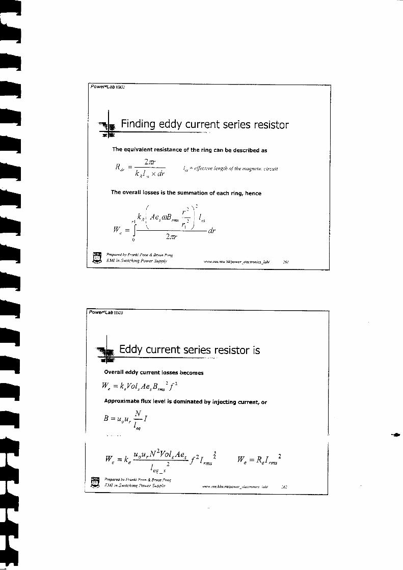
It
th-t
ttt
ItIt
tItII
Powet4LabHKu
Prepared bv Fronki Poon & Boan Pong
EMI in Switchinq Power gypp!1'
w"=k,*++g.f,r,^,i' e q s
V[/" = R"I, ,
Eddy current series resistor is
Overall eddy current losses becomes
W" = k,Irol,AerB,^'f'
Approximate flux level is dominated by injecting current, or
MB = u o u r ! - l
I' e q
Hr9
PoweFLabHKu
The equivalent resistance of the ring can be described as
) r rn
r ) e l
1\.t, = -;-----; 1"" = e/fective length rdthe magnetic circuitK R l , ,s x d r
The overall losses is the summation of each ring, hence
Prepared hy Franki Poon & Boan Pong
EMI in Switching Power Supply wv eee. hku. hApwer _e learcnq -l ob/
'w\|.eee.hku.hApower:4eanhrca_iah/ :62

Power.Lab HKU
Total losses becomes
W, = (Rn+Ro) I , . . r 2
and, , , , , r r ]
D I t \ - t - ' t t ) L ' t " t V O I '
,t t 1 , \ J ) - Nh - - ] __ -7 - Jlu, - . r-
L(0
R,(J') = k"uou, .N2Vol . ,Ae. ,
, 1I nq -r-
J-).
Rn(O
fi P.epare<t hv Franki Pcon & Bman Ponq
*L t.Ut in Swtchtng Power Suppl.v \rw \|. eee. h ku. h ly'powe r _e I e c t m n t6 -! a b/
PoweFLabHKu
t.I te -
Wror"rfrB ,r'
: the coefficients
-Wroor. f rBr '
-f, fr 'B ort B or'Ae,vol,- -fr' -frB or' B or' Ae,vol,
k n =w ror"r fr' B p22 - w rorrrfr'� B r'�
-frfr'B or'B rr'vol, - -fr'"-frB or'B ortvol,
Fflr-!tPrepared bv Frcnki Pcon & gryan PonL
E'Vl in Swilching Power Supplv
Ferrite losses
'ee\|.cee. hku.hAtu\eer electbnics idb/
tI

Power'Lab HKU
Ferrite losses- some approximated idea
c € l ( a n d € F
Prepared bv Franki Poon & Bilan Pong
EMI in Swrtching Power Supply ww. eee. h ku. hUpoqr clec trcn i6, ab/
Power.Lab HKU
Series resistor can bemuch higher thanwinding resistance,
Inductance fall at around
N=707
HSCZ T0mmtorcid
A. = 0,07 cm2
L" = 2'2 cm
Prepred hv Franki Poon & iJnan Pong
EMI in Switchine Power Supplv
- lnlorwleld qu@bnl sfrt @ra bttat dgstafta- lntwlet& hdrctercc
S€das c@ bJs rusblrnct
\wweee.hku.hUFnwer_electmnrcs_lab/ :66
Ferrite losses resistor
0n
il6'
r r r f '
T
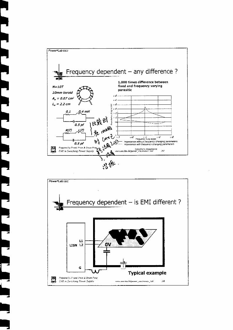
*.k
TI!Tt!FTFlFFFrBh
Fh
t '
h!t
Frequencydependent - any difference?
N=7OT
7Omm toroid
A. = 0,07 cmz
Le = 2.2 cm
1,000 times difference betweenfixed and frequency varyingparasitic
0.1
r . 1 d
r . r d
g r . r d
, 1 1 0
e r ' 1 0
Power*Lab HKU
Prepared by Franki Poon & Bdan Pons
EMI in Swtching Power Supplv
Power.Lab ilKu
Typical example

Power.Lab HKU
EMI is different - typical example
50 pfVpeak =4OO V
T r = 5 0 n s
T f = 5 0 n s
P w = 2 u s
Per = 5.6 us0.03 pf
Resonate occurs due to Land C, But you seldom seeresonance after adding
{01i ,i0{} : S L! i.rl i;Kr ii$r
269
Prepared hv Franh P,ton & Bryan Pong
EMI in Switching Power Supply ww. e ee. h k u. h A lnwe r -e I ec r rcn i t _! a b/
ground choke.2200 pf
2 5 u H I
25r l
0.5 pf
0.4 mH 0,1
htttIbI-
tITT
EMI is different - changing L and CThe inductor change it's value atwhere it should resonate. Dampingresistor increase at resonatefrequency
Prepared bv Franki Poon & Edan Pong
E,VI in Swtching Power Suopl.v
- shi€ld & tilteQd CM noise without FGq. paremateE
CM noise with Frcq. dependent lilter
vww eee-hku-hl</gtwer Jlectronrcs _iah/ :70
50 pf
2200 pf
2 5 u H 1
2:t n
o.5 pf

r|
ThI
-
PoweFLabHKu
Changing L and C - no more simple
Prepared hv Franki Poon & Bryan Pong
EMI in Swilching Power Supply ww. e ee. h * u. h l</powr _t I e c t rcn ru _l ab/ 271
prediction
22OO pf
2 5 u H 1
25 r l
0.5 pf
Filter designp 1 -
minate
. S t e p 2 -order
Power.LabHKu
I
+ Example 2 - ferrite beadRsirlo8e d hhctMel Log.tdlc)
oX
A small ferritebead givesalmost 1O flat 10O MHz,while keeping0.O1O only at10O kHz.
o r . r l , . r o o r . r o j r . r d ' r . t o 7 r . r o * t . r o )Fary(os@U
- Equiwlat con lw s*iq rcbtwc* E_futiye indactwc agai8t ftqu^cy
Core {oss seria rqisrance & lndrctmce agairetlrequency
ff i PrcW.i bv F.dnh Poon & Boan i 'onq
d]\, E,UI n Swtrchinq power Supplv tww. e ee. h ku. h A trnwer _e I e c t mh Es -l o b/

PowercLab ilKu
E x a m p l e 3 - s e r i e s C M C
5O pf 5 p f
High u,for high impedance atlow frequency
ffi Prepared hv Franki P,rcn & Bman Punq
E , EMI n Switchinq Power Supply
Low arfor high impedance athigh frequenry
www.eee.hku.hUptwerelectmniulab/ :73
PoweFLabHKU
Series CMC - cheap alternative
50 pf 5 p f
High n for high impedance atlow frequency
Prepored bv Franh i,oon & 9ruan Pon(
E,Vl in Swnching Power Suppllt
Low stray capacitpor formedium impedance at highfrequency
www tee.nku.hldwwer electnnics lab/ :71
rl
TI

r|I
hhttttt
PoweFLab HKU
I"'q[ Short SummaryPermeability of a high permeability ferrite usuallystart to roll off at around 200kHz.So it usually give maximum impedance at thatfrequency
. Resistive Losses can be very high depending onM and P.The equivalent loss resistor pay a great role infiltering design to provide damping effect.Magnetic material do not work on the way Iapproximate. It is more complicated and highlynon-l inear.
ffi P.ewrecl bv F.onki Poon & 3mun Ponq
I!, EMI in S.ttching Power Supptv \ww. e e e, h ku. h Apowr _e I ec r ro n i6 _l a b/
PoweFLabilKu
finy uhtfiqutntion?flB{lt
t>repared bv Franki Poon & Boan Pong
E.Vl in Switchinq Power Supplv 'n \|. eee. hku. hkrwwer jlecrmntcs _iab/ :76
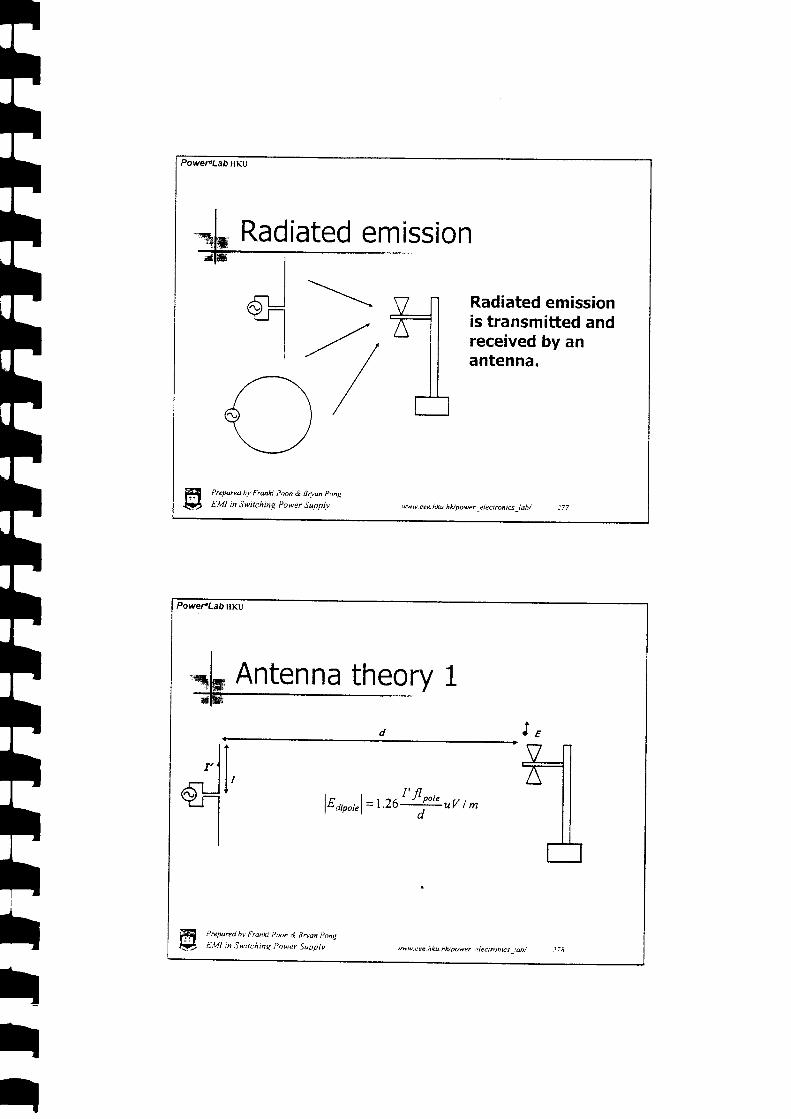
Power"Lab HKU
Radiated emissionI
d sJrl - / , a l l
\ / [ ]
Radiated emissionis transmitted andreceived by anantenna.
Prepnred by Franki Poon & Bryan Pong
EMI in Switching Power Supply "vw. eee. h ku. hUpower el ect rcnt6 | abl
Power.LabHKU
I
5k Antenna theory 1
l lr 1 l
6-'.Jt'I
Il , orr"l= 1.261' f lJo'" uv / m
t. E
_LfrllilA
Hq!?Prcpared hv Fronh Pooh d EDdn pong
EMI in Switchiaq Power Supplv 'ww.eee.nku hhpwcr tlecrnnrs tab/
III

, d ,
I J rIl tt
-\I
t t nI t t t
. l = t ) 6 '' ' r c
tared bv Franki Poon
I in Switchng Pou
r|hhh
f l
hth
I
hhlhItIIIII
Antenna theory 2
| | , , , f l r t '
lu,,, , ,r l= l i l 6x lo-t ') | ' , ! ' t tv ' m
cl
I
9-Jq lt lt l
E
Preryred h)' Frcnki Poon & Bryon Ponq
EMI in Switching Power Supply ww. e ee - h ku. h Apowe r _e I ec t rc n tu -l a b/
Dipole - capacitive like antenna
rww.eee.hiu.hl4utwert lectrcnrcsluir / )80

o.31pf--/
ww. eee. h ku. h Apowr _e I e c t rc n i cr _l a b/
PoweraLab HKU
ol;;}__{ill l \ - / l- - l
I tPrepared hv Franki Poon & Bdan Ponta
EMI in Switching Power Suppll,EN.ila
r|r|tr|r|r|r|r|tIIIIIItttttt
Cable and converter - 10m simulation
lz o,r","l= t.zo I fli''" uv t *s rd r.rd r.nO z.d z.srf
FBq@rcy- C|SPR22 ndieted class B limit lins- 10m radidtad noise amt trcm dipole
10m rcdiated noise generated by cabte
rww cee.hku.hlapower _,4ecrmntcs _lob/ :82
Limit Exceeded !!Vp€ak =40O
T r = 5 0 n s
T f = 5 0 n g
h v = 2 u s
Ps = 5,6 us siq
*
r0.31pf
PowePLabHKu
fi P,epared bv Fronki ?oon,l Bruan I'ong
V, E.Ul n Swtchrnq Power Suoplv

Power.Lab HKU
tE
l - | , ^ t 2 . 1 1 'lE r " r l = l 3 l . 6x 1g - t v ! - - ! ! - uV t m
I P.eparetl bv Franki Pun & Bddn pong
) E,VI in Swtching Power Supplv 'Nw. cee. hku. hvwwcr c I ec I mn t6 I ub./
ttth-
IIT
Power.LabHKU
Loop antenna - current source excitation
f., ,-, = O.5A
C-*=o'ae 7tr=So ns A \tr=f lons (f l)r=o.oooz)t * = 2 u s \ 6 : /T= 6.6us
\.-/
Very very little noise isgenerated
| | . . t 2 l t '
, E n u o l = l i I . 6 ^ 1 0 - t ' t ' " " t t V i md
ssE
s.rf r.rd r.1rd z.i z.stl :.rdtsaq@ncy- C|SPR?2 nidatad clas I limit line- 10m radiatdd noise emittad frcm cui€nt source toop
10m radiated noise by loop antenna
'ww eee.hku.hAgtwer 4ectruntcs lob/ :81fi
PreOmd bv F,onki poon & Bruan pon!
V, E.Vll n Swiching Powvr Suopl.r,
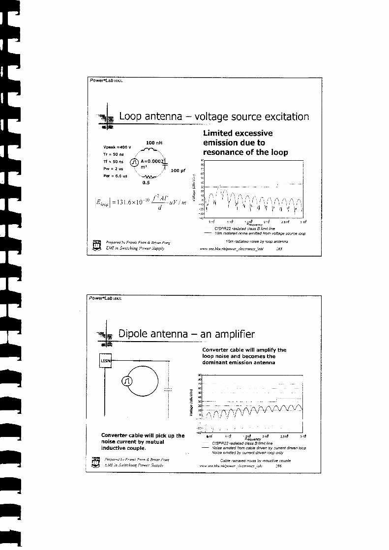
Power.Lab nKU
Loop antenna - voltage source excitationLimited excessiveemission due toresonance of the loop
100 nHVpeak =40O V
...i,\rar.T r = 5 0 n s
rf = so ns f?f n=O.OOOZIP w = 2 u s Y t ' f
1OO pfPer = 6.6 us
0.5
, r , ^ l ' | l t '
lg , . .^- l = i i I .6 x 1g- to J '11 , ,v 1 .
| ' " " P 1 d
a
ili iltl l^i/y
Prepared hv Franki Poon & Bn'an Pong
EMI in Switching Power Supplv
s . rd r . rd r 5 rd 2 . f i : . : rd ; rdFrcquency
- C|SPR22 raidated class I limit line- 10m rcdiated noisa emilled frcm voltage source ioop
.1Om radiated noise by loop antenna
ww.eeehks.hupow.r_elecrrcnis-lab/ :8J
IIIItIrt
PowerlLab \KU
Converter cable will pick up thenoise current by mutualinductive couple.
fi l,rorur"q 5, p,anxr ltrn & Bnan pont
l#. t,Ut n Swilchmq Po\|er Suoplv
Dipole antenna - an amplif ier
ss
:
loop noise and becomes thedominant emission antenna
*1d tad r5rd z'rd 2s10 r.rdFEq@Ny
- C|SPR22 Ediatad class I limit line- Noise emilted frcm cable drivan by curent dnven loop
- Noise emittad by curenl diven i@p only
Cable ndiatad no6e by nductive couple)ww.eee.hku.hUpower-elecntnrcs_iuh/ :86

Power.Lab nKu
Cable and converter - suppression
l il r i1 . . . i . .
A iY i/ :
\ > i\ i
6 i
By passnoise \current
Small CMC
Prepared bv Franki Poon & Bman Ponq
EMI in Switching Power Supply ww. ee e. h ku. h Apow r -e I e c t rcn iu _l ab/
IIthItT
Power.LabHKu
Loop antenna - suppression
Ferritebead
Add ferrite bead atthe current loop
Ferrite bead
t'repsled hv Franki Poon & Bdon Pong
Elvll in Svtching Power Supp$, ^Nw cce.hku ntlpowcr ,:lcctronics ,tb/

PoweraLabHKU
I
Th Short summary. F
. Cables generally emit more noise than loop
. A loop can emit substantial noise atresonate condition.
' A cable acts as an amplif ier & picks up noisefrom a loop close by and emits at a muchgreater level.
' Impedance with small stray capacitance andhigh resistance can reduce radiated noise.
Preparerl bv Franki Poon & 9ryan Pong
EMI in Switching Power Supply rww.eee.hku.hk/power_electtuni6 _lab/ :89
Power"Lab HKU
radiated EMI
vii-t,
Predicting
I
ItIII

Assuming input and outputcable are the same and thereceiving antenna is 10maway
,, 254 E ti.,, , noY ttsN nF Linit =:=:-:-lu-L./.O Jl cabte
rfla
Arti f icial Limit l ine of CISPR22measured at LISN
rrd rril r.sd z.tt zsd^ FQq@rcy
- AtTificial class E limit line for 1m cabtee Aftificialclass B limit line lor 2m cable* Atlificial class B limit line for 3m cabla
Atlilicial rcdiated class E limlt lne
\!w. eee. h ku. h lq pow r -e I ec | rcn E\ _i a b /
so
s
r|IhhhI
Fh
nII
It
rrd
Power.Lab lrKU
Misc. - Predicting radiated EMI
J ,,,_o
As E field is generated by adipole
I t t ll - | , ^ . ' J ' n o l , '
lE Lir"ul= | '26--:--::::-uv I m
The corresponding current l imitf lowing in the input cable is
t r )| - u L t m r t " r n t lr | , - ; r - - t V
I .26 JI , obto
The corresponding voltage l imitmeasured at the USN
v'ri-i,
E6-1fi> r'u-it4 vii-i, t/E L',,,dZ L's,u ,_
1 0 6I .26 / l c ,b te
ffi Preporecl bv Franki Poon & Bdan p.nq
\fi E.Vl in Swrrching Power Supplr vww. eee. h ku. hUpower e lect rcni6 lab/
JqMrIz -230MHz
230MHz- tG
fuasi peak linit(l0n I SOaAuVclass 8) ',
im37dBuV/m
Prepored hv Franki Poon & Snan Pong
labi :92

Powel.Lab HKU
firry shufiqunntjon?H Preparecl by Franki Pnn & Bnan Pong
EMI in Switching Power Supply wveee.hku.hUpower_rlectrcnt*_lab/ :9J
Powet LabHKU
MISC - Cancellationv,
F
A full-bridge configuration has an inherentcancellation ofvoltagesring. The left leg will having an egud but opposite swing comparedwith the right leg.
H{t
Prepored bv Fronki l)oon & Bdan pong
EMI in Switchine Power Suoplv .ww aee. hku. hlvoower elecrrcnics ldb/

tI
II
Power.Lab HKU
I.,, ---\.,, C, * = Ca t- _ l _ | -
Then,
Vvictim = O
Prepnred bv Frann Poon & Bnon Pont
EMI in Switching Power Supplv w w. e ee. h ku. h Apowr _e I e c t rcn i u _l a b/
Power.Lab HIKU
MISC - capacitive coupling cancellation
A two wheeler forward or flybad< configuradon has an inherentcancellation of voltage swing, The leS leg has an equal but oppositeswing compared with the right leg.
ffi ?n'oarea bv Fronki P,,rn & Bnun t'nng
V E.VI :n Swtkhtnq P,twer Suppiv .w\9 ee.hku hvpower _,:lectmnics _loh/ )96

PowefLab HKU
A general method forvoltage cancellation canmake use of an anti phasewinding to complete thetask.
.1Tt^';'-L4.'-t^"\-
t- ,-- II lbooorn | |l 4 l
Prepore<l bv Fronki Poon & Bryan Pong
EMI in Swirching Power Supply w w - eee. h ku. h ll pow e r _e I e c r rcn i a _l a b/
PoweFLabHKu
MISC - capacitive coupling cancellationA 20 ns delay wil l el iminate thecancellation effect at 10 MHz
/5it) = Vs1(t+;0 ns)
Be careful withtime delay !
P,"pur"d hv Fronki P^on & Btuon Pnns
E.Vll in S)eitchinq Power Suoolv
' . r ld r .rd rroT r.rdFaucty (LoE iut.)
- ,Yomalized spectrun o[Vg1
- .\lomolize<l specttun ol VSI(|)-r'St(tsTd)
Yonaii:e<i notse source spectrum
tw\|.eee.hku.hldpowerllectronrcs_iab/ )98

Powel'Lab HKU
A single frequency injection into to a receiver make the detector producea dc voltage output with ripple where the peak, quasi-peak and averageare the same
Prepnreu hv F.anh Poon & Bnnn Pong
EMI in Switching Power Suppl;t t*w- eee- hku. h Apowe r _e I ec trcn i6 _l ab/
PoweFLab HKL)
Misc - Frequency jitter-ingO.SHz
7,7fs
lower value.
Prepared bv Franki Poon tl B^,an Pong
Etr4l in Switching Power jupply,
avaragad valueforfrquanty.mdubdott
7/f_
A changing frequency injection into tbe receiver make the detectorproduce a pulsing output voltage where the averag€ value will have much
,ww.eee-hku.h l tDo\ |e r r lec tmncs \$ / j00
ItIIr|

I
PowereLab ilKu
, l| -----_I.t L . \ \ \ \ lr * - . l
Band pesJfilter movingalong thefreguency axis
f{t)=fs+l/2kpwx(t)
. . . . . . . . . . . . . . f t .
time for a frequency changing signal
: : : : : f: : : : :: : : : !
i i : i :
Envelop det&tor output against time for a t. frquency changing signal
rrepared Dv r fonkt roon & a^'on Ponp
EMI in Swtching Power Suppl.y |9w\9.eee.hku.hL/power-electrcni6-tab/ i0r
Frequency
Power.Lab HKU
Don(fBW) = normalized averagevalue at the detector output
' 8 Wi l + -
Donlf a*) = l ui, Pdf (f)dJf"J -_;
The frequency jitte? in a way
"f :.fs + l/2kpWsin(2nf^t)
The probability density functionof the operating frequency is
The average value undera sine wave modulationwill have a factor shownbelow
es
Pdf (f) =' - a s r f - . r s r d _ ' s s r d ' o r d6eno pass illeas centof trequency
Averaged Btio kf=2 BW=gkHz
I'reparel hv F tonkt Poon .l tJwan Ponq
EMI in.Switchtnq Power Suoplt,
Average ratio
'qvw.*e-hku.hkio,twerjlectronrcs,iob/ 102

PoweFLab fiKu
n n/ \ / \/ \ / \Linear type modulat ion
A A ^ l \A t \I V V V V V \
White noise modulat ion
t \ A ^ i lni \I V V V V V \
Chaotic type modulation
Prepared bv Franki Poon & Bryon Pong
EMI in Switching Power Supplv
Yield flat frequencydistribution
Aqflwww. ee e. h ku. h Upaw r _e I e c t rcn i t _l a b/
PowefLabHKu
Band ,ass ftItermovealongftquancyaxb
f{t)=b+Y21pg1rr,
tII
Frequency will overlap at high frequency range.
H l'rcFzreti bv F,ankr Phon & 3ryan pong
& E,Vfl :n iwttshinq Power \upplt 'ww eee.nku.nlopower _. lectrcnrcs _ ao/

Power.Lab HKU
Misc - Frequency' f itteringIf f- << time constant of peak orquasi-peak detector charge time
f,(t)=fs+l/2kpwx(t)
. . . . . . . . . . r i '
Band passftlter movealongfrequency axis
Don't be cheated by the spectrum screed !Prepored hy Franki Poon & Bryan Pong
EMI in Swttching Power Supply ww. eee. h *u. h A power _e I ec t mn iu _l a b/
Frcquen.y
' 1 . . . . . . . i . . ! . .
:
IIIIIII
Power.Lab HKU
I
3k Input cable*]*
Refresh
Cy = 22oo pf
Prepared hv Frunci Poon & gruan Pone
EMI in Swuchrng Power Supplv ww. eee. hku-n Hytwer _el ectmn tcs.�l ab/
No input cable parameteris considered.
No problem !
t . &
cMC = 20 mH +0.5n// sopf
*=
/'I
: t t i r, 1 ! i :
Hr:!t

Power.Lab ilKU
l -.-qh Input cableInput Cable
Input Cable
usN ZI
'F -4Cy O'37Pf
Consider theinductance ofeach wire
Prepare.l hy Franhi Poon & Brvon pong
EMI in Switching Power Supplv ww.eee.hku.hk/pwet etec,rcniq lab/ j07
L2 Z )} -d-tacv T ' o.3
Power.LabHKu
I
=b Input cable
A I
l, = 0.002/(ln (L - o.l r)"n" d
For a 1m cable
l = l O O a n
d =O.7 qn
hene
L = 7 , 5 u H
Input Cable
H ?rcpared hv F.onkt po(,n & Bruan pong
{ LVI in Swttchtnq power jupplv .vww eee nku nlowrver ,lcctntnrcs .,tnt

rtIIIIIIIIItIhhIIttIIr|
Power.Lab HKU
.sP! - rrR*tvfBi*o
ut cable - cEble inductance
: I i : N . t { 0 r r : . t x . K ,: I tS i i )
Prepnred bv Franki Poon & Boan Pong
EMI in Switching Power Supply
J0(! {0sr i08n i.Nr: {u l in i : t
tFtrrr
w. eee. hku h lupower -e lycrmn tu _, abi
f , t ' . i l t : i s l
J09
PoweFLabHKU
Consider themutual and selfinductance of theinput cable
2 t wLtz = 0.0021 (1n(:) - I + --)uH' ' w ' I 'Fora 1m cabl€
I = 7(XI otr
W= O,4cm
hence
L p = 7 u H
Input Cable
H P.eparea hv F.ann poon d Sryan pailq
$ E.VI n Swrrchnq Power Supptv wbree.hku.hfupo\'er,clecrmnta_lab/ II0

Power€Lab HKt
FIIr|r|IIIIIIIIIIIIItItI
ri l : , i l .r. i f i ,a i 0-r. I ft i : i h tryi. i I
: i L J , 5 r . . .
Preparel h.r' Franki Poon & BDan Pohg
EM m Switching Power Suppit w w u,. eec. h k u. h lu powe r _e I e c t rc n i ct _i o br--'it-€t
Consider themutual capacitor,mutual and selfinductance of theinput cable
Input cable - inductance & capacitor
r_ 0.08851 trc,c - ' n F
w rI / ^ .t n r / _ I
t la
ffi P.eforcd h, fronh Poon & Boan pong
$rr. - €,lZl i" Su itchtng Power Suppl.r
For a lm cable
l = l O O c m
W = O . 4 c m
hene t
C = 5 4 p f
w _
Input Cable
27 pfeach
Power.Lab HKL
27 pfeach
tlusNl i
lL2r-|..T.. :.
I c i '
+Z Z :I
-h
Z-T
cy T ' 0.37pfCy
wu eee. hku. h Alnwer _electrcn ics *lab I

PowefLabHKU
cable - inductance & capacitance
i0r,
i ! [ i
PoweFLabHKu
able - inductance & capacitance
frqu?rcDafea bv Frankr Prytn & Bruun t'onc
EMI in Switching Power gupply
Input c
Solution6vw eee. hku. hl(po\9er eiectrcnrcs lab/ J H

PowefLabHKu
I
ah Short SummaryI F
. An anti-phase noise source is a possiblesolution to eliminate noise.
r Frequency j ittering or modulation canreduce average reading.
r Input cable construction contributes tonoise distribution pick up by the LISN.
'ffi Prepared bv Franh Poon & Bnan Ponq
V EUt in S.itching Power Supply w.eee.hku.hupowr-electtuni6_lab/ I 15
PowefLabHKu
Faraday shield produceemore invisible loops
Prcpdred hv Franki i)oon & Snun l'ong
E:VI in Swtching Power Suoplv
Good or Bad ?
.t'ww.eee.itku.hlloower llectronics ;db/

Power{Lab HKU
D'courea hr F,anxt P.on d Brttn p ,ny
EMI in Switchinp Power Suopiv
Add choke or CMC will pick up more noisee
IIr|r|IIr|r|
PoweraLab |KU
Increase number of turns will increase straycapacitance
ffi Prepared hv F,anxt pun & Bn,an pong
Sj E,Vt in S-rching Po\9er Suppl.y w\'. eee. h ku. hApo|9e r _e I ec I m n i6 -l a b/
Good or Bad ?
Good or Bad ?
6ew tpe .nku Fboo\ tp r . re (mntc t ab j l ) l

.Lfg;+.=�ffi
MWffi*wwffiffi?
Power.Lab HKU
Pr'pared hv !1nil !'hn & 3Nrn ,,an\
E.lll in Switchinq Power.\upplv ,ww eee. h ku. hH N\9er t I ec tio nics I abl
Question ?
Ir|FhhhhhhhhtIIIthIII+l
ffiMffiffiffimm
ffi P.epared hv F,onki Puon & Bnan pong
$ t.Ut in Switcning Power Supplv wv eee. hku. hUpower clectroniu lab/ J I 9
PoweFLab nKU

PoweraLab HK:],
Statement 1 - All my corect solution doesn't work
Statement 2 - If there exist a solution
Logic derivation - The solution mustbe incorrect !
H Prcpared bv Franki Poon & Bman Pong
$ EUt i" Snirching Power Suppl.y w.eee.hku.hApowr_electrcnis_lab/ 321
Simple logic
PoweFLabHKIJ
Sometimes we have to
*$s$d*t
Preoored bv Franki Poon d Eoan Ponl
EMI in Switching Power Supplv
1:>j
ww. e ee. h ku. h A powe r -c I e c t mn rcs _l a b/

r|FF
IhI
IFFhhhtTtI
t
Pow€l'Lab HKU
Overall SummaryEMI behaviorsummation ofdiscussions.It is never anEMI result.
iS,a l l
at least, aof the above
I easy task to predict
Better understanding helpprevention and diagnosis.
g Ptepared hv Franki Poon & BNon Pong
EMI in Switching Power Supply w. ee. h ku. hApwr -e I ecttu ni6 -l aU
Power.LabAKU
Prepared bv Franki Poon & Bryon Pong
EW in Switching Power Supplv w eec.hku.hvpower clectrcntE lail
t1l, Tim Willlam, EMC for product Designers, Butterworth-Heinemann Ltd.1994
l2l. Jeffrrey P.Mill, Electro-magnetic Interference Reduction in ElectonicSystems, PTR Prentlce Hall, Engl€wood Cliffs, Ncw Jers€y 07632, 1993
t3l. Mark D. Herema, Designlng for Etectrrmagnedc Compatlbility, Hp1l949BH€wlett Packard.
t4l. Dongbing Zrangi Dan Chcri Sablc* D. NorlndnCc dlttbrenth&modG rotsocauscd by ground cur"entln anol?-ltnerpowersupptr. Irowcf,El€cEonb+adaltrtgCon ercnca; 1998; pESrC 9& R€co|tL 2g{t}Annual IEEE volumc3 2r feeC^ fag!(q;ltilt-ltlXlvolz j. .] -
I51. \tei Zhang; Zhang, M.T.; Leq F.C; RoudcG,Jt ChvchE,CondudElf!aralysb of a boost PFrcdrcl|it, Applt€d porH Fl€eb.onk*Con{brtncrandEqdtfonr1997. APEC'97 Confer€nce Proce€dlngs 1997., TWellUr Annual Volume-; t,';ggt ,Page(s): 2Il -229 vol.l,
Reference
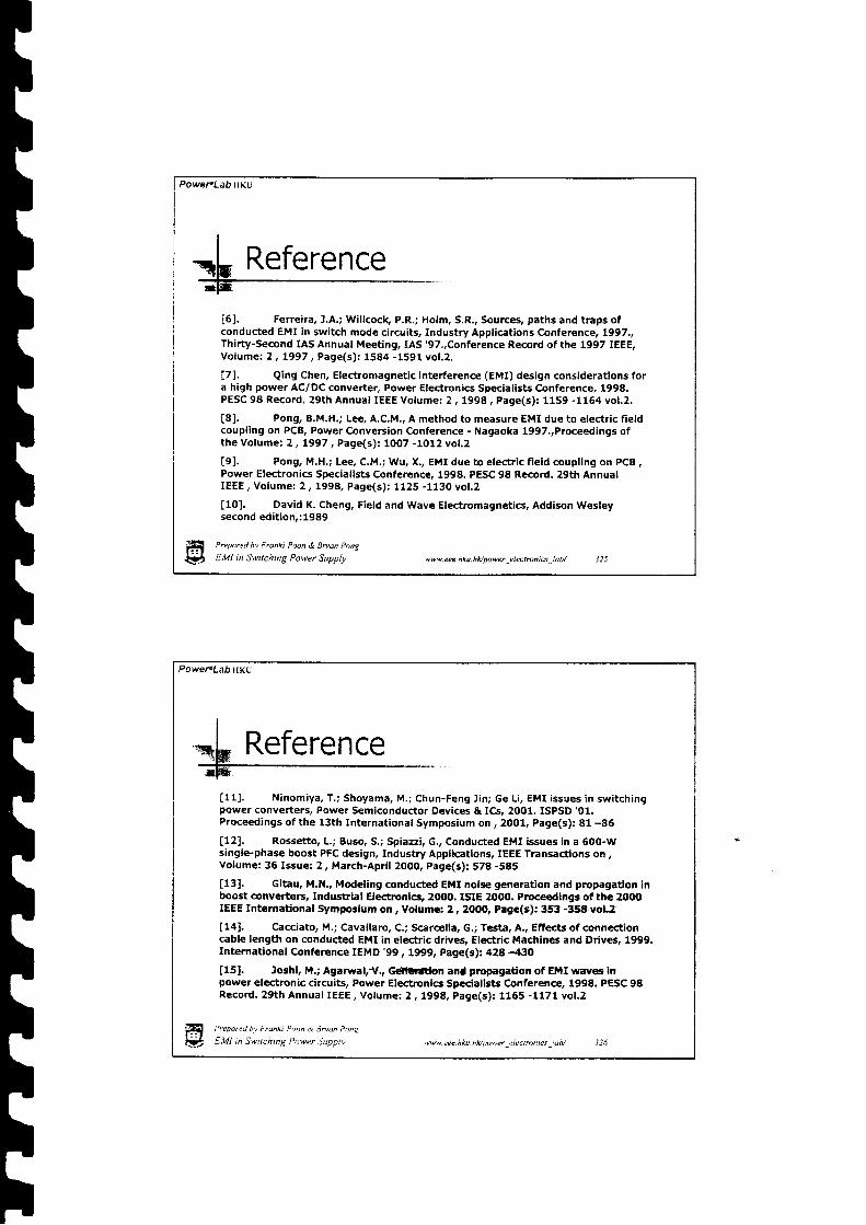
hTTttI
PoweFLab rrKU
I-o[ Reference
i5l. Ferreira, J,A.; Willcock, P.R.; Holm, S.R., Sources, paths and traps ofconducted EMI in switch mode circuits, Industry Applications Conference, L997.,Thirty-Second IAS Annual Meeting, IAS '97.,Conference Record of the 1997 IEEE,Vofume: Z, L997, Page(s) : 1584 -1591 vol .2,
17l. Qing Chen, Electromagn€tic interference (EMI) design considerations fora high power AC/DC converter, Power Electronics Specialists Confer€nce, 1998,PESC 98 Record. 29th Annual IEEE volume: 2, 1998, Page(s) : 1159 -1164 vol .2,
t8l. Pong, B,M.H,; Lee. A.C,M., A method to measure EMI due to electric fieldcoupling on PCB, Power Conversion Conference - Nagaoka lgg7,,Proceedings ofthe Vofume: 2, L997, Page(s) : 1007 -1012 vol .2
tgl. Pong, M.H.; Lee, C.M.; Wu, X., EMI due to electric field coupling on pCB ,Pow€r Electronics Specialists Conference, 1998. PESC 98 Record, 29th AnnualIEEE, Volume: 2, 1998, Page(s) : 1125 -1130 vol ,2
[10]. David K. Cheng, Field and Wave Electromagnetics, Addison Wesleysecond edition,:1989
Prepared bv Fronki Poon & Bryan Pong
EMI in Swttching Power Supply ww.eee.hku.hlt/power_elecrrcniu-lab/ J25
Powet"Lab HKU
[11] , Ninomiya, T. ; Shoyama, M.; Chun-Feng l in; Ge Li , EMI issues in swi tchingpower converters, Power Semiconductor Devices & ICs, 2001, ISPSD '01.
Proceedings of the 13th International Symposium on , 2001, Page(s): 81 -86
[12]. Rossetto, L.; Buso, S,; Spiazzi, G., Conducted EMI issues in a 6OO-Wsingle-phase boost PFC design, Industry Applications, IEEETransactions on,Volumes 36 Issue: 2, March-April 2OO0, Page(s): 578 -585
t131, Gitau, M.N., Modeling conducted Ett{I nois€ gen€ration and propagadon inboost converters, Industrlal Electronics, 2000. ISIE 2OO0. Proce€dlngs of the 2OOOIEEE Internadonal Symposium on , Volume: 2 , 2OOt0, Page(s): 353 -358 vol.2
t141. Cacciato, M.; Cavallaro, C,; Scarcella, G.; Testa, A., Effects of connectioncable length on conducted EMI in electric drives, Electric Machines and Driv$, 1999,Int€rnational Conference IEMD '99, 1999, Pag€(s): 428 -430
[15]. loshl, M.; Agarwal,"'1r,, GdltGftlon and prcpagaHon of EMI way€r inpowe. electronic circuits, Power Electronics Specialists Conference, 1998. PESC 98Record, 29th Annual IEEE, Volume: 2 | L998, Page(s): 1165 -1171 vol.2
f i Prepar"a bv trdng o /)n, t 3oan P.ns
&5 f .W in Swuchtnq Power iuaprv \w\'.cee.hku.hldpo\|er electnnics !db/
Reference
PoweFlab HKU
Prepared bv Frunki Poon & Bruan Pong
E;VI in Swirching Power Supply ww.cee.hku.hluwwr electrcnts lab/
!rei. okyere, P,F.; Heinemann, L., computer-aided analysis and reduction ofconductedEMI in switched-mode power converter, Applied power El€ctronics conference andExposition' 1998, APEC '98. conference proceedings 199g., Thirteenth Annual , volume: 2,1998, Page(s) : 924 -928 vot .2
[17]. Ferreira, J.A,; Willcoclq p.R.; Holm, S.R., Sources, paths and traps of conductedEMI in switch mode circuits, Industry Applications conferenc€, 1997, Thirty-s€cond IAsAnnual Meeting, IAs '97., conference Record of the 1997 IEEE, volume3 z', LggTt page(s):1584 -1591 vol .2
i181. Wei Zhang; Zhang, M.T.; Lee, F.C,; Roudet, J.; Clavel, E., Conducted EMI analysis ofa boost PFC circuit, Applied power Electronics conference and Exposition, 1997. ApEc'97conference Proceedings 1997., Twelfth Annual , volume: | , tggT rage(sj: 223 -z2g vol.r,
!rg:. Bardos, P.' Predicting the EMc performance of high frequency inverters, AppriedPower Electronics conference and Exposition, 2o01. ApEc 2001. sixteenth Annual rEEE,Vofume: L ,2OOt, Page(s) : 213 -219 vol .1
Reference
PoweFLabHKu
Prcpared bv Frantt Poon & 7n,an ponc
E,VI in Switching Power Supplv ww. eee. hku.hlc/mwer -electonrcs _iab/ Jld
II
"- I P aforc' ? t t r l \ l s l t g l \ -rss rnce
t2ol. Laboure, E,; Costa, F.; Gautier, C.; Melhem, W., Accurate simulation ofconducted interferences in isolated Dc to Dc converters regarding to Er.rIstandards, Power Electronics specialists conference, tgg6, prscig6 Record.,27th Annual IEEE , Votume: 2 , !996, page(s): 1973 -1978 vol.2
!211, Knurek, D.F., Reducing EMt in switclr mode power supplles,lgt^aolmulications Energy conference, fggs. fNfeLiC ,ee., 16ih Inierna$onat ,1988, Page(s):411 -4ZO
l2Z!. Poon, R,K.; Liu, Cp.; pong, M.H, Leastcoupltng paths model fur non-contact EMI base on lump element approach ln swltch moie converter. pow€rElectronlcs speciarlsts conferenc€, 2ob1. pEsc, zoot rEEE 32nd Annuir, volumo.2 , 2AOt Page(s): 577 -SB2 vol.2
LZSI. .- _Paolo Tentl, Giorgio Spiazi, One-day Course ofi €l€ctromagnedcCompaUbility in Industrial Equipment: Stand#d, problems and Soluuon, IEEEHong Kong Joint Chapter of power Engineering, Industry Application, powerElectronics and Industrial Electronics Societies, 25 Feb. 2OO2

[e[e, lmlsspuallf,
Prepored bv Fr@hi Poon & |ru@ Pong
QI E,V] i, Sn rching Power Supplv ww.ue.hku.hvpowr_electtuni$_lav 329
r|r|r|r|tttr|