numerical modeling of boundary layer control using ...webx.ubi.pt/~pjpo/mefte2012c.pdf · numerical...
TRANSCRIPT

1
Numerical Modeling of Boundary Layer Control Using Dielectric Barrier Discharge
M. Abdollahzadeh, J. Páscoa, P. Oliveira
University of Beira Interior, Department of Electromechanical Engineering, Center for Aerospace Sciences and Technology, Covilhã, Portugal
Email: [email protected] http://clusterdem.ubi.pt
Abstract
A numerical investigation of flow control was performed to determine the effect of Dielectric Barrier Discharge (DBDs) actuator to modify the characteristics of a flow over an airfoil and to examine its ability to prevent flow separation. Moreover, in this computational study, several parameters have been studied to evaluate the effectiveness of plasma actuator including actuator position and the mode of actuation. The case under consideration includes a flow past a NACA 0021 airfoil at 23 deg angle of attack and an external velocity of 35 m/s with a single DBD actuator. A 2D computational model was developed to simulate the incompressible turbulent flow over the airfoil. A body force treatment is devised to model the effect of plasma actuator and link the plasma dynamics and fluid dynamics. The body force can be derived from first principles. In order to compute this body force vector, the model solves two additional equations: one for the electric field due to the applied AC voltage at the electrodes and the other for the charge density representing the ionized air. Comparisons with previously published works show the accuracy of the obtained results. These results demonstrate that the discharge can induce an important acceleration of the flow close to the surface and therefore cause a decrease in the size of separation bubble.
Keywords: Flow control; Plasma actuator; Dielectric barrier discharge; Separated airflow;
1 INTRODUCTION
The application of active flow control is very important in the field of aeronautical applications. Efficient flow control systems are capable of manipulating the flow to achieve certain desired effects, such as drag reduction, mitigation of noise pollution, and help increase reducing stall margins on airfoils. In order to achieve these results two main techniques are used; separation control and laminar-to-turbulent transition suppression. The most popular flow control methods usually involve the use of mechanical flaps, suction and blowing techniques, piezoelectric actuators, synthetic jets, as well as MEMS devices. A detailed review on active flow control techniques can be found in [1].Recently, the introduction of plasma actuators in the field of aerodynamics has demonstrated to be very promising to achieve flow control at reduced cost and weight. Plasma-based devices exploit the momentum coupling between the surrounding gas and plasma to manipulate the flow. Unlike other flow control techniques, such as suction and mechanical actuators, plasma actuators require low power consumption, involve no moving mechanical parts, and have a very fast frequency response that allows real-time control. For these reasons, the plasma actuator has become a very promising and attractive device in the flow control community. Plasma actuators can be sub-categorized into two major families: the corona discharge, and the dielectric-barrier-discharge. Recently, the most commonly used plasma actuator has become the single-dielectric barrier- discharge (SDBD). Two electrodes are typically separated by a dielectric barrier usually glass, Kapton or teflon as depicted in Figure 1. When a high AC voltage signal, of sufficient amplitude (5-40 kV ) and frequency (1-20 kHz), is applied between the electrodes the intense electric field partially ionizes the surrounding air producing a non thermal plasma on the dielectric surface. The collisions between the neutral particles and accelerated ions generate a net body force on the surrounding fluid leading to the formation of the so called “ ionic wind” . The body force can be used to impart the desired flow control outcome on a given fluid system. For the SDBD configuration the momentum coupling of the plasma and fluid induces an initial vortex
MEFTE 2012 IV Conferência Nacional em Mecânica dos Fluidos, Termodinâmica e Energia
Lisboa • LNEC • 28 e 29 de maio de 2012
2
that propagates downstream. Very promising results for the application of plasma actuators have been observed in a wide range of applications. Hanson et al. [2] were able to effectively control transient growth instability in a Blasius boundary layer and delaying transition through the injection of a counter-disturbance into the boundary layer using plasma actuators, their results were obtained experimentally. Separation control has also been successfully achieved for a wide range of bodies, including a NACA 0015 airfoil, a cylinder and a hump in the presence of a turbulent boundary layer [3-6]. Other applications include the control of a rotor blade wake [7], increasing the lift on a UAV [8], and noise reduction [9]. In this paper, we intend to numerically model the controlling effect of DBD’s on NACA 0021 at angle of attack of 23 and M=0.1 and investigate the effect of electrode positions on the performance enhancement of plasma actuators. The center line of the actuators was placed at x/C = 0, 0.016131, 0.049581 respectively. Results have been demonstrated through comparison of Lift and Drag coefficient and comparison of the size of separation zone around the airfoil.
2 PROBLEM STATMENT AND BOUNDARY CONDITION
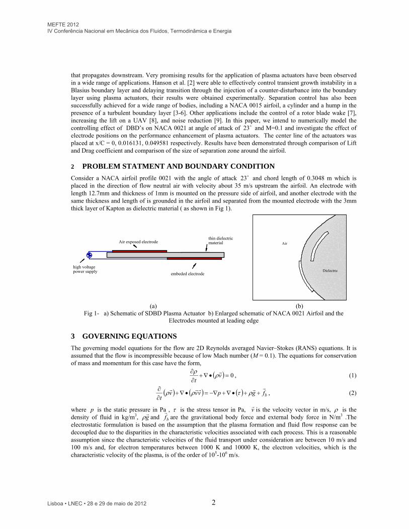
Consider a NACA airfoil profile 0021 with the angle of attack 23 and chord length of 0.3048 m which is placed in the direction of flow neutral air with velocity about 35 m/s upstream the airfoil. An electrode with length 12.7mm and thickness of 1mm is mounted on the pressure side of airfoil, and another electrode with the same thickness and length of is grounded in the airfoil and separated from the mounted electrode with the 3mm thick layer of Kapton as dielectric material ( as shown in Fig 1).
Air exposed electrode
embeded electrode
thin dielectricmaterial
high voltagepower supply
Air
Dielectric
(a) (b) Fig 1- a) Schematic of SDBD Plasma Actuator b) Enlarged schematic of NACA 0021 Airfoil and the
Electrodes mounted at leading edge
3 GOVERNING EQUATIONS
The governing model equations for the flow are 2D Reynolds averaged Navier–Stokes (RANS) equations. It is assumed that the flow is incompressible because of low Mach number (M = 0.1). The equations for conservation of mass and momentum for this case have the form,
0
vt
, (1)
bfgpvvvt
, (2)
where p is the static pressure in Pa , is the stress tensor in Pa, v
is the velocity vector in m/s, is the density of fluid in kg/m3, g
and bf
are the gravitational body force and external body force in N/m3 .The
electrostatic formulation is based on the assumption that the plasma formation and fluid flow response can be decoupled due to the disparities in the characteristic velocities associated with each process. This is a reasonable assumption since the characteristic velocities of the fluid transport under consideration are between 10 m/s and 100 m/s and, for electron temperatures between 1000 K and 10000 K, the electron velocities, which is the characteristic velocity of the plasma, is of the order of 105-106 m/s.
MEFTE 2012 IV Conferência Nacional em Mecânica dos Fluidos, Termodinâmica e Energia
Lisboa • LNEC • 28 e 29 de maio de 2012
3
The plasma actuators are formed by a pair of electrodes separated by a dielectric material. The actuator is placed in the surface with one electrode exposed to the surroundings and the other one embedded in the surface below the dielectric material (Figure 1).When a high-voltage AC is supplied to the electrodes, this arrangement causes the air in their vicinity to weakly ionize. The ionized air in the presence of the electric field gradient produced by the electrodes, results in a body force vector acting on the external flow that can induce steady or unsteady velocity components. This body force can be expressed in terms of the applied voltage and incorporated into the Navier Stokes equations. By neglecting magnetic forces, the electrohydrodynamic (EHD) force can be expressed as
Ef cb
(3)
where, bf
is the body force per unit volume, c is net the charge density and E
is the electric field. This body force is a body force per volume of plasma. This body force is the basis of the plasma actuator effect on neutral air. Considering the Maxwell equations (respectively Gauss law, Gauss law for magnetism, Faraday's law of induction and Ampere’s circuital law) :
,,,0,t
DJH
t
BEBD c
(4)
where H
is the magnetic field strength, B
is the magnetic induction, E
is the electric field strength, D
is the electric induction , J
is the electric current. We assume that the charges in the plasma have sufficient amount of
time for the redistribution process and the whole system is quasi-steady, and that the time variation of the magnetic field is negligible, as is often the case in plasma. These assumptions imply that the electric current J
,
the magnetic field H
, and the magnetic induction B
are equal to zero, as well as the time derivatives of the electric tD /
and the magnetic induction, tB /
.Therefore, the Maxwell’s equations give rise to
,0, ED c
(5)
The relation between the electric induction and the electric field strength:
ED
, (6)
where is the permittivity. The permittivity can be expressed as r 0 where r is the relative permittivity of the medium, and 0 is the permittivity of free space. Using Eq. (6), Eqs (5) can be rewritten as :
,0, EE c
(7)
This implies that the electric field can be derived from the gradient of a scalar potential:
E
(8) Therefore,
0 c
r (9)
If we use the Boltzmann relation we have:
Tk
en
Tk
enn
bbie
1exp 00, (10)
with being the local electric potential, and 0n the background plasma density, T the temperature of the species, the elementary charge e , and the Boltzmann constant bk . In the above equation, the positive sign applies to electrons and the minus sign applies to the ions. The net charge density at any point in plasma is defined as the difference between the net positive charge produced by ions and the net negative charge of electrons. The difference can be related to the local electric potential , by the Boltzmann relation (10). Assuming a quasi-steady state with a time scale long enough for the charges to redistribute themselves, the following relation can be written
)exp(exp)(0
0
00
ebibei
c
Tk
e
Tk
eennn
e
(11)
Where in and en are the ion and electron densities in the plasma. Expanding the exponential functions in a Taylor series for T , Equation (11) becomes, to lowest order of T/
MEFTE 2012 IV Conferência Nacional em Mecânica dos Fluidos, Termodinâmica e Energia
Lisboa • LNEC • 28 e 29 de maio de 2012
4
)11
(0
02
0 ebib
c
TkTk
ne
(12)
The Debye length which is the characteristic length for electrostatic shielding in a plasma, is defined as
2
1
0
02
)11
(
ebibd TkTk
ne
(13)
The free charges in the plasma are shielded out in a distance given by the Debye length. The Debye shielding is valid if there are enough particles in the charge cloud. The criteria for this is the dimensionless plasma parameter, , that characterizes unmagnetized plasma systems, defined as
ed n3
3
4 (14)
If the plasma parameter is 1 , then it means that the plasma is weakly-coupled, and the Debye shielding is valid. For plasma with the Debye length of approximately 0.00017 m and the density of the charged particles is on the order of 1016 particles/m3 , the criteria is 5105.3 , indicating that the assumption of the Debye shielding is true. With the use of definition of Debye length we have:
2
0
1
d
c
(15)
Experiments indicate that independent of which electrode the voltage is applied to, and independent of the polarity of the applied voltage, the resultant body force and therefore the induced flow is in the direction towards the embedded electrode. The exposed surface of the dielectric plays a critical role. Even before the air ionizes, the dielectric surface communicates the potential charge from the covered electrode. When the voltage potential is large enough to ionize the air, the surface of the dielectric collects or discharges additional charge. As a result the dielectric surface is referred as a virtual electrode. Therefore there is the need for a better model that can account for these effects. According to [10-11] (Split potential field model), since the gas particles are weakly ionized, we can assume the potential can be decoupled into two parts: one being a potential due to the external electric field, , and the other being a potential due to the net charge density in the plasma, ,
(16)
Assuming that the Debye length is small and the charge on the wall above the encapsulated electrode is small, the distribution of charged particles in the domain is governed by the potential due to the electric charge on the wall and is unaffected by the external electric field. Note that the grid spacing should not be larger than the Debye length. The smaller the Debye length, the narrower the plasma region located near the electrode and dielectric surface becomes.For the potential due to the external electric field, we have:
0 r , (17)
and for the potential due to the net charge density, we have,
0 c
r (18)
Using Eq. (15) we can rewrite Eq. (18) as follows,
2d
ccr
(19)
3.1 Boundary Condition
Equation (17) is solved for the electric potential, , using the applied voltage on the electrodes as boundary condition. The applied AC voltage is imposed at the exposed (upper) electrode as boundary condition:
)()( max tft (20)
The wave form function )(tf can be either a sine wave or a square wave given by,
MEFTE 2012 IV Conferência Nacional em Mecânica dos Fluidos, Termodinâmica e Energia
Lisboa • LNEC • 28 e 29 de maio de 2012
5
),(
0)2sin(;1
0)2sin(;1)(
wave),sine()2sin()(
wavesquaret
ttf
ttf
(21)
where is the frequency and max is the amplitude. The embedded electrode is prescribed as ground by setting the electric potential to zero on that electrode. At the outer boundaries 0/ n is assumed. The wave form function )(tf is a time dependent boundary condition and can be used to model both steady and unsteady actuator arrangements. For the steady case, )(tf can be set to be a square wave. For unsteady cases, different frequencies and wave forms can be used to simulate actuation with different duty cycles. Equation (19) is solved for the net charge density c , only on the air side of the domain. A zero normal gradient for the net charge density is imposed on the solid walls except in the region covering the lower electrode. The charge density is set to zero on the outer boundaries. On the wall downstream of the exposed electrode where the embedded electrode is located (virtual electrode), the charge density is prescribed in such a way that it is matched with the time variation of the applied voltage )(t on the exposed electrode,
)()()( max, tfxGt cwc (22)
where maxc is the maximum value of the charge density allowed in the domain ( 3/ mC ). The variation of the
charge density on the wall, wc, in the streamwise direction, x , is prescribed by a function )(xG chosen to resemble the plasma distribution over the embedded electrode. Experimental results suggest that this distribution is similar to a half Gaussian distribution given by
0)2/)(exp()( 22 xforxxG (23)
In equation (23) is the location parameter indicating the x location of the maximum, and is a scale parameter determining the rate of decay. The location parameter is chosen such that the peak corresponds to the left edge of the embedded electrode. Moreover, it is assumed that takes a value of 0.3 to allow a gradual decay of the charge density distribution from the left edge to the right edge. It should be noted that in order to solve the above equation, it is necessary to specify two parameters, namely, max
c and d . These parameters control the strength of the plasma actuator's effects on the flow field and extent of these effects into the flow field. These two parameters should be calibrated using available experimental data. The values for max
c and d were empirically defined by Suzen et al. (2005) [] as 4108 C/m3, and 0.001m. Since Eqs (17) and (19) do not contain a time derivative term. Therefore, Equation (17) can be normalized using the value of voltage of the exposed electrode, )(max tf and be solved by imposing a constant boundary condition equal to unity at the upper electrode. Once the dimensionless distribution is determined, the dimensional values at any given time can be obtained by multiplying this distribution with the corresponding value of )(max tf . Similarly, equation (19) can be solved by normalizing with )(max tfc . This implies that the boundary condition for the dimensionless charge density on the wall region covering the embedded electrode is )(xG . Non-dimensional form of Eqs (17) and (19) is as follows.
)(
,0max
**
tfr (24)
)(
,max
*2
**
tfrc
cc
d
cc
(25)
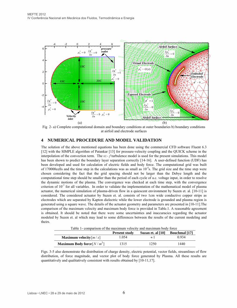
The corresponding boundary conditions and the computational domain are shown in Fig 2.
MEFTE 2012 IV Conferência Nacional em Mecânica dos Fluidos, Termodinâmica e Energia
Lisboa • LNEC • 28 e 29 de maio de 2012
6
-4 -2 0 2 4 6
-4
-2
0
2
4
6
15C
21C15C
15C
Velocityinlet
pressureoutlet
EmbededElectrode
Virtual Electrode
Exposed Electrode
Airfoil Surface
Airfoil Surface
(a) (b) Fig 2- a) Complete computational domain and boundary conditions at outer boundaries b) boundary conditions
at airfoil and electrode surfaces
4 NUMERICAL PROCEDURE AND MODEL VALIDATION
The solution of the above mentioned equations has been done using the commercial CFD software Fluent 6.3 [12] with the SIMPLE algorithm of Patankar [13] for pressure-velocity coupling and the QUICK scheme in the interpolation of the convection term. The υ2 - f turbulence model is used for the present simulations. This model has been shown to predict the boundary layer separation correctly [14-16]. A user-defined function (UDF) has been developed and used for calculation of electric fields and body force. The computational grid was built of 170000cells and the time step in the calculations was as small as 10-5s. The grid size and the time step were chosen considering the fact that the grid spacing should not be larger than the Debye length and the computational time step should be smaller than the period of each cycle of a.c. voltage input, in order to resolve the dynamic motions of the plasma. The convergence was checked at each time step, with the convergence criterion of 10-7 for all variables. In order to validate the implementation of the mathematical model of plasma actuator, the numerical simulation of plasma-driven flow in a quiescent environment by Suzen et. al. [10-11] is considered. The considered actuator by Suzen et. al. consists of two 1cm wide conductive copper strips as electrodes which are separated by Kapton dielectric while the lower electrode is grounded and plasma region is generated using a square wave. The details of the actuator geometry and parameters are presented in [10-11].The comparison of the maximum velocity and maximum body force is provided in Table.1. A reasonable agreement is obtained. It should be noted that there were some uncertainties and inaccuracies regarding the actuator modeled by Suzen et. al which may lead to some differences between the results of the current modeling and theirs.
Table 1- comparison of the maximum velocity and maximum body force Present study Suzan et. al [10] Bouchmal [17]
Maximum velocity ]/[ sm 1.054 1 0.934
Maximum Body force ]/[ 3mN 1315 1250 1440
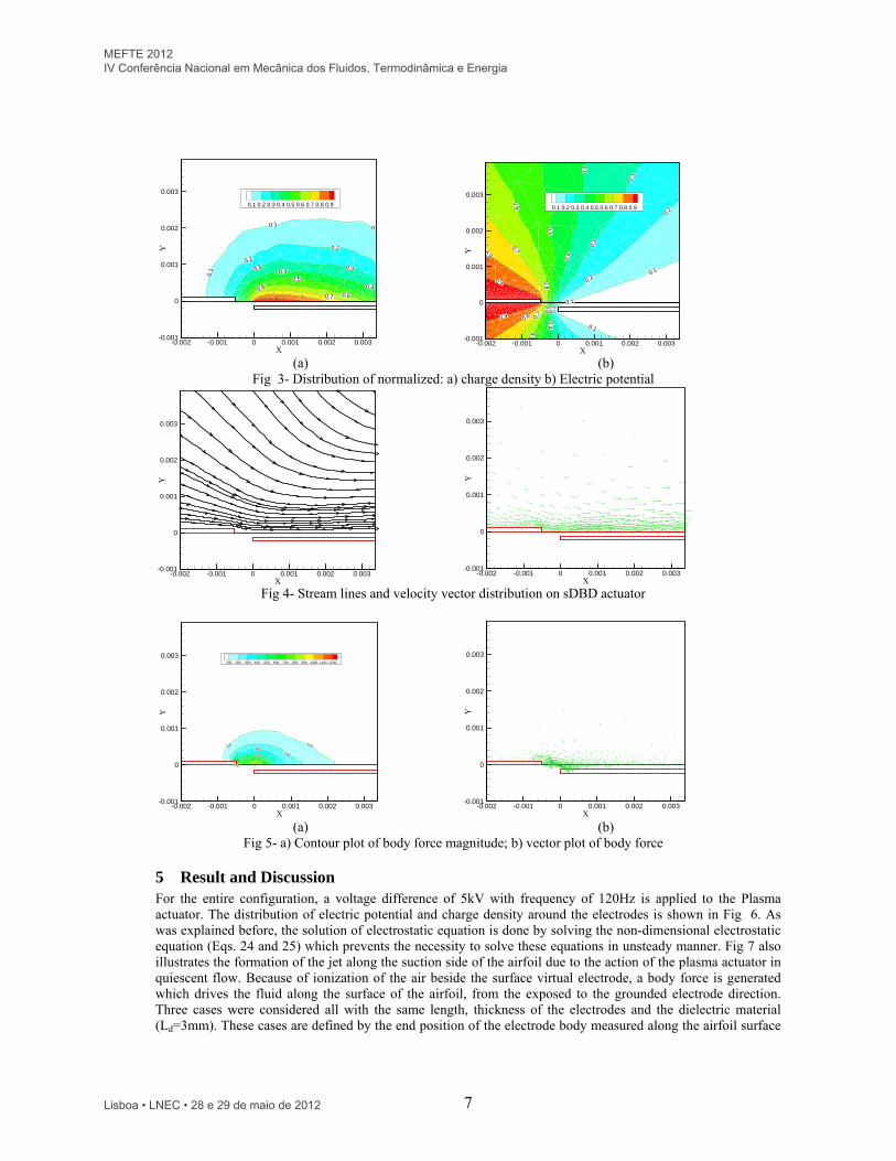
Figs. 3-5 also demonstrate the distribution of charge density, electric potential, vector fields, streamlines of flow distribution, of force magnitude, and vector plot of body force generated by Plasma. All these results are quantitatively and qualitatively consistent with results obtained by [10-11,17].
MEFTE 2012 IV Conferência Nacional em Mecânica dos Fluidos, Termodinâmica e Energia
Lisboa • LNEC • 28 e 29 de maio de 2012
7
0.10.1
0.1
0.2
0.20.30.3
0.4
0.40.5
0.60.6
0.7
X
Y
-0.002 -0.001 0 0.001 0.002 0.003-0.001
0
0.001
0.002
0.003
0.1 0.2 0.3 0.4 0.5 0.6 0.7 0.8 0.9
0.1
0.1
0.1
0.2
0.2
0.3
0.3
0.3
0.4
0.4
0.4
0.5
0.5
0.6
0.6
0.6
0.7
0.7
0.8
0.8
0.9
0.9
X
Y
-0.002 -0.001 0 0.001 0.002 0.003-0.001
0
0.001
0.002
0.003
0.1 0.2 0.3 0.4 0.5 0.6 0.7 0.8 0.9
(a) (b)
Fig 3- Distribution of normalized: a) charge density b) Electric potential
X
Y
-0.002 -0.001 0 0.001 0.002 0.003-0.001
0
0.001
0.002
0.003
X
Y
-0.002 -0.001 0 0.001 0.002 0.003-0.001
0
0.001
0.002
0.003
Fig 4- Stream lines and velocity vector distribution on sDBD actuator
100100
200
300
400
500
X
Y
-0.002 -0.001 0 0.001 0.002 0.003-0.001
0
0.001
0.002
0.003100 200 300 400 500 600 700 800 900 1000 1100 1200
X
Y
-0.002 -0.001 0 0.001 0.002 0.003-0.001
0
0.001
0.002
0.003
(a) (b)
Fig 5- a) Contour plot of body force magnitude; b) vector plot of body force
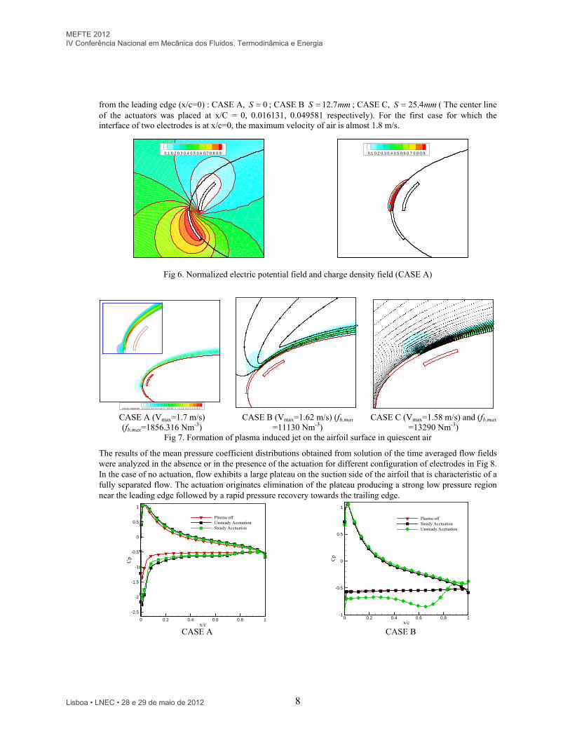
5 Result and Discussion For the entire configuration, a voltage difference of 5kV with frequency of 120Hz is applied to the Plasma actuator. The distribution of electric potential and charge density around the electrodes is shown in Fig 6. As was explained before, the solution of electrostatic equation is done by solving the non-dimensional electrostatic equation (Eqs. 24 and 25) which prevents the necessity to solve these equations in unsteady manner. Fig 7 also illustrates the formation of the jet along the suction side of the airfoil due to the action of the plasma actuator in quiescent flow. Because of ionization of the air beside the surface virtual electrode, a body force is generated which drives the fluid along the surface of the airfoil, from the exposed to the grounded electrode direction. Three cases were considered all with the same length, thickness of the electrodes and the dielectric material (Ld=3mm). These cases are defined by the end position of the electrode body measured along the airfoil surface
MEFTE 2012 IV Conferência Nacional em Mecânica dos Fluidos, Termodinâmica e Energia
Lisboa • LNEC • 28 e 29 de maio de 2012
8
from the leading edge (x/c=0) : CASE A, 0S ; CASE B mmS 7.12 ; CASE C, mmS 4.25 ( The center line of the actuators was placed at x/C = 0, 0.016131, 0.049581 respectively). For the first case for which the interface of two electrodes is at x/c=0, the maximum velocity of air is almost 1.8 m/s.
0.1 0.2 0.3 0.4 0.5 0.6 0.7 0.8 0.9
0.1 0.2 0.3 0.4 0.5 0.6 0.7 0.8 0.9
Fig 6. Normalized electric potential field and charge density field (CASE A)
velocity-magnitude: 0.1 0.2 0.3 0.4 0.5 0.6 0.7 0.8 0.9 1 1.1 1.2 1.3 1.4 1.5 1.6 1.7 CASE A (Vmax=1.7 m/s) (fb,max=1856.316 Nm-3)
CASE B (Vmax=1.62 m/s) (fb,max =11130 Nm-3)
CASE C (Vmax=1.58 m/s) and (fb,max =13290 Nm-3)
Fig 7. Formation of plasma induced jet on the airfoil surface in quiescent air
The results of the mean pressure coefficient distributions obtained from solution of the time averaged flow fields were analyzed in the absence or in the presence of the actuation for different configuration of electrodes in Fig 8. In the case of no actuation, flow exhibits a large plateau on the suction side of the airfoil that is characteristic of a fully separated flow. The actuation originates elimination of the plateau producing a strong low pressure region near the leading edge followed by a rapid pressure recovery towards the trailing edge.
x/c
Cp
0 0.2 0.4 0.6 0.8 1
-2.5
-2
-1.5
-1
-0.5
0
0.5
1
Plasma offUnsteady AcctuationSteady Acctuation
x/c
Cp
0 0.2 0.4 0.6 0.8 1-1
-0.5
0
0.5
1
Plasma offSteady AcctuationUnsteady Acctuation
CASE A CASE B
MEFTE 2012 IV Conferência Nacional em Mecânica dos Fluidos, Termodinâmica e Energia
Lisboa • LNEC • 28 e 29 de maio de 2012
9
x/cC
p
0 0.2 0.4 0.6 0.8 1
-1.5
-1
-0.5
0
0.5
1
Plasma offSteady AcctuationUnsteady Acctuation
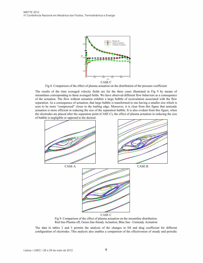
CASE C Fig 8. Comparison of the effect of plasma actuation on the distribution of the pressure coefficient
The results of the time averaged velocity fields are for the three cases illustrated in Fig 9 by means of streamlines corresponding to these averaged fields. We have observed different flow behaviors as a consequence of the actuation. The flow without actuation exhibits a large bubble of recirculation associated with the flow separation. As a consequence of actuation, that large bubble is transformed to one having a smaller size which is seen to be more “compressed” closer to the trailing edge. Moreover, it is clear from this figure that unsteady actuation is more efficient in reducing the size of the separation bubble. It is also evident from this figure, when the electrodes are placed after the separation point (CASE C), the effect of plasma actuation in reducing the size of bubble is negligible or opposed to the desired.
CASE A CASE B
CASE C Fig 9. Comparison of the effect of plasma actuation on the streamline distribution. Red line-Plasma off, Green line-Steady Actuation, Blue line –Unsteady Actuation
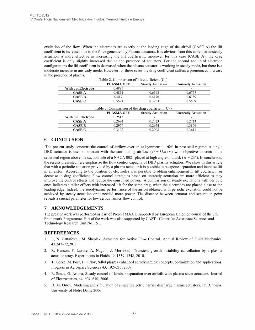
The data in tables 2 and 3 permits the analysis of the changes in lift and drag coefficient for different configuration of electrodes. This analysis also enables a comparison of the effectiveness of steady and periodic
MEFTE 2012 IV Conferência Nacional em Mecânica dos Fluidos, Termodinâmica e Energia
Lisboa • LNEC • 28 e 29 de maio de 2012
10
excitation of the flow. When the electrodes are exactly at the leading edge of the airfoil (CASE A) the lift coefficient is increased due to the force generated by Plasma actuators. It is obvious from this table that unsteady actuation is more effective in increasing the lift coefficient; moreover for this case (CASE A), the drag coefficient is only slightly increased due to the presence of actuators. For the second and third electrode configurations the lift coefficient is decreased when the plasma actuator is working in steady mode, but there is a moderate increase in unsteady mode. However for these cases the drag coefficient suffers a pronounced increase in the presence of plasma.
Table 2. Comparison of lift coefficient (CL) PLASMA OFF Steady Actuation Unsteady Actuation
With out Electrode 0.4885 - - CASE A 0.4851 0.6398 0.6777 CASE B 0.417 0.4176 0.6139 CASE C 0.5521 0.3953 0.5509
Table 3. Comparison of the drag coefficient (CD) PLASMA OFF Steady Actuation Unsteady Actuation
With out Electrode 0.2513 - - CASE A 0.2694 0.2723 0.2713 CASE B 0.2976 0.2974 0.3866 CASE C 0.3102 0.2908 0.3611
6 CONCLUSION
The present study concerns the control of airflow over an axisymmetric airfoil in post-stall regime. A single DBD actuator is used to interact with the surrounding airflow ( smU /35 ) with objective to control the
separated region above the suction side of a NACA 0021 placed at high angle of attack ( 23 ). In conclusion, the results presented here emphasize the flow control capacity of DBD plasma actuators. We show in this article that with a periodic actuation provided by a plasma actuator it is possible to postpone separation and increase lift in an airfoil. According to the position of electrodes it is possible to obtain enhancement in lift coefficient or decrease in drag coefficient. Flow control strategies based on unsteady actuation are more efficient as they improve the control effects and reduce the consumed power. A comparison of steady excitations with periodic ones indicates similar effects with increased lift for the same drag, when the electrodes are placed close to the leading edge. Indeed, the aerodynamic performance of the airfoil obtained with periodic excitation could not be achieved by steady actuation or it needed more power. The distance between actuator and separation point reveals a crucial parameter for low aerodynamics flow control.
7 AKNOWLEDGEMENTS The present work was performed as part of Project MAAT, supported by European Union on course of the 7th Framework Programme. Part of the work was also supported by CAST - Center for Aerospace Sciences and Technology Research Unit No. 151.
REFEREENCES 1. L, N. Cattafesta , M. Sheplak ,Actuators for Active Flow Control, Annual Review of Fluid Mechanics,
43,247–72,2011
2. R. Hanson, P. Lavoie, A. Naguib, J. Morrison, Transient growth instability cancellation by a plasma actuator array. Experiments in Fluids 49, 1339–1348, 2010.
3. T. Corke, M. Post, D. Orlov, Sdbd plasma enhanced aerodynamics: concepts, optimization and applications. Progress in Aerospace Sciences 43, 192–217, 2007.
4. R. Sosaa, G. Artana, Steady control of laminar separation over airfoils with plasma sheet actuators, Journal of Electrostatics, 64, 604–610, 2006.
5. D. M. Orlov, Modeling and simulation of single dielectric barrier discharge plasma actuators. Ph.D. thesis, University of Notre Dame.2006
MEFTE 2012 IV Conferência Nacional em Mecânica dos Fluidos, Termodinâmica e Energia
Lisboa • LNEC • 28 e 29 de maio de 2012
11
6. D. M. Orlov, T. Apker, C. He, H. Othman , T. C. Corke, Modeling and Experiment of Leading Edge Separation Control Using SDBD Plasma Actuators, AIAA 45th Aerospace Sciences Meeting, 8-11 January 2007, Reno, Nevada
7. S. Lemire, H. D. Vo, Reduction of fan and compressor wake defect using plasma actuation for tonal noise reduction. Journal of Turbomachinery 133,2011
8. Grundmann, S., Frey, M., Tropea., C., Unmanned aerial vehicle (UAV) with plasma actuators for separation control. 47th AIAA Aerospace Sciences Meeting Including the New Horizons Forum and Aerospace Exposition in Orlando Florida, 2009–698.
9. F. Thomas, A. Kozlov, T. Corke, Plasma actuators for cylinder flow control and noise reduction. AIAA Journal, 46, 1921–1931,2008
10. Y. B. Suzen, P. G. Huang, Simulations of Flow Separation Control using Plasma Actuators , 44th AIM Aerospace Sciences Meeting and Exhibit, Reno, Nevada, 9 - 12 January 2006.
11. Y. B. Suzen, P. G. Huang, J. D. Jacob, D. E. Ashpis, Numerical Simulations of Plasma Based Flow Control Applications, 35th Fluid Dynamics Conference and Exhibit June 6-9, 2005, Toronto, Ontario AIAA 2005-4633
12. FLUENT 6.3 Documentation.
13. S.V. Patankar, Numerical heat transfer and fluid flow, Hemisphere Pub. Corp., 1980
14. P. Durbin, Separated flow computations with the k -ε-v2 model, AIAA Journal, 33 659–64, 1995.
15. P. Durbin, Computation of transonic flow with v2–f turbulence model, International Journal of Heat and Fluid Flow 22 53–61, 2001.
16. S. Perneix, P. Durbin, M. Behnia, Computation of 3-D turbulent boundary layers using the v2-f model, Flow Turbulance and Combustion. 10,19,1998
17. A. Bouchmal, Modeling of Dielectric-Barrier Discharge Actuator, Delft University of Technology, Master of Science Thesis. March 2011
MEFTE 2012 IV Conferência Nacional em Mecânica dos Fluidos, Termodinâmica e Energia
Lisboa • LNEC • 28 e 29 de maio de 2012