nfpa 69 - پارسیان اطفاء ایرانیان
TRANSCRIPT
Copyright NFPA
NFPA 69 Standard on
Explosion Prevention Systems
2002 Edition
Copyright © 2002, National Fire Protection Association, All Rights Reserved
This edition of NFPA 69, Standard on Explosion Prevention Systems, was prepared by the Technical Committee on Explosion Protection Systems, and acted on by NFPA at its May Association Technical Meeting held May 19–23, 2002, in Minneapolis, MN. It was issued by the Standards Council on July 19, 2002, with an effective date of August 8, 2002, and supersedes all previous editions.
This edition of NFPA 69 was approved as an American National Standard on July 19, 2002.
Origin and Development of NFPA 69
In 1965, an NFPA Committee was appointed to develop standards for explosion protection systems. These standards would include information on inerting to prevent explosions and on venting to minimize damage from an explosion.
A tentative draft on explosion prevention systems was presented at the NFPA Annual Meeting in New York City in May 1969. This tentative document was officially adopted in May 1970. NFPA 69 was revised in 1973 and reconfirmed in 1978.
In 1982, the Committee on Explosion Protection Systems began a thorough review of NFPA 69, including the development of a chapter on the technique of deflagration pressure containment. The results of that effort became the 1986 edition.
The 1992 edition of NFPA 69 incorporated a new chapter, on deflagration isolation systems. Partial amendments were made to refine definitions, improve descriptions of oxidant concentration reduction techniques, improve material on deflagration suppression, and finetune deflagration pressure containment material.
The 1997 edition of this standard included some reorganization and updating of the technical material to improve its usability. New material was added on enrichment to operate above the upper flammable limit as a means of explosion protection with minimum oxidant concentrations for preventing explosions. Material was added for provisions on reliability of explosion protection control systems and deflagration suppression systems for consistency
Copyright NFPA
with other NFPA standards.
The 2002 edition of NFPA 69 includes new information on spark detection and extinguishment system design. A reorganization of the protection methods now reflects a hierarchy based upon the degree of explosion prevention. The LOC values for gases and vapors in Annex C have been updated based upon recent research. The standard has been revised to reflect NFPAManual of Style requirements.
Technical Committee on Explosion Protection Systems
David C. Kirby, Chair Dow Corporation, WV [U]
Richard F. Schwab, Vice Chair Honeywell, Inc., NJ [U]
Luke S. Morrison, Secretary Professional Loss Control Inc., Canada [SE]
Joe R. Barton, Fountaintown, IN [SE]
William J. Bradford, Brookfield, CT [SE]
Reinhard E. Bruderer, PredEngineering Inc., FL [U] Rep. CibaGeigy Corporation
Kenneth L. Cashdollar, U.S. National Institute of Occupational Safety & Health, PA [RT]
Kris Chatrathi, Fike Corporation, MO [M]
Henry L. Febo, Jr., FM Global, MA [I]
Mark A. Fry, Mark A. Fry & Associates, Inc., NJ [SE]
Joseph P. Gillis, Westboro, MA [SE]
Stanley S. Grossel, Process Safety & Design, Inc., NJ [SE]
Dan A. Guaricci, ATEX Explosion Protection L.P., FL [M]
Michael D. Hard, Hard Fire Suppression Systems, Inc., OH [IM] Rep. Fire Suppression Systems Association
David D. Herrmann, E.I. duPont de Nemours & Co., DE [U]
Walter B. Howard, Omaha, NE [SE]
Copyright NFPA
George Lobay, Canada Department of Natural Resources, Canada [E]
R. A. Mancini, BP Amoco Corporation, IL [U] Rep. American Petroleum Institute
Steven A. McCoy, National Starch & Chemical Co., IN [U] Rep. NFPA Industrial Fire Protection Section
Robert W. Nelson, Pocasset, MA [I] Rep. Industrial Risk Insurers
John Joseph Plunkett, U.S. Coast Guard, DC [E]
Mitchel L. Rooker, BS&B Safety Systems, OK [M]
Kevin Sheddrick, Engineered Storage Products Co., KS [M]
Timothy F. Simmons, Eastman Kodak Company, NY [U]
Bill Stevenson, Cv Technology, Inc., FL [M]
Stephen M. Stuart, Marsh USA, Inc., MI [I]
Erdem A. Ural, Fenwal Safety Systems, MA [M]
Roy A. Winkler, Solutia Inc., MO [U]
Robert G. Zalosh, Worcester Polytechnic Institute, MA [SE]
Alternates
Laurence G. Britton, Union Carbide Corporation, WV [U] (Alt. to D. C. Kirby)
Gary A. Chubb, Chubb Engineering, KS [M] (Alt. to K. Sheddrick)
David G. Clark, E. I. duPont de Nemours & Co., DE [U] (Alt. to D. D. Herrmann)
Ettore Contestabile, Canadian Explosives Research Laboratory/CANMET, Canada [E] (Alt. to G. Lobay)
Thomas A. Gray, Akzo Nobel Inc., IL [U] (Alt. to S. A. McCoy)
Copyright NFPA
Edward J. Haas, Jr., Marsh USA, Inc., NY [I] (Alt. to S. M. Stuart)
Paul F. Hart, Industrial Risk Insurers, IL [I] (Alt. to R. W. Nelson)
George A. Krabbe, Automatic Fire Controls, Inc., AZ [IM] (Alt. to M. D. Hard)
Arnold L. Mundt, BS&B Safety Systems, OK [M] (Alt. to M. L. Rooker)
Samuel A. Rodgers, Honeywell, Inc., VA [U] (Alt. to R. F. Schwab)
Joseph A. Senecal, Fenwal Safety Systems, MA [M] (Alt. to E. A. Ural)
Nonvoting
Vladimir Molkov, University of Ulster at Jordanstown, United Kingdom SE]
Harry Verakis, U.S. Dept. of Labor, WV
Guy R. Colonna, NFPA Staff Liaison
Committee Scope: This Committee shall have primary responsibility for documents on explosion protection systems for all types of equipment and for buildings, except pressure venting devices designed to protect against overpressure of vessels such as those containing flammable liquids, liquefied gases, and compressed gases under fire exposure conditions, as now covered in existing NFPA standards.
This list represents the membership at the time the Committee was balloted on the final text of this edition. Since that time, changes in the membership may have occurred. A key to classifications is found at the back of the document.
NOTE: Membership on a committee shall not in and of itself constitute an endorsement of the Association or any document developed by the committee on which the member serves.
NFPA 69 Standard on
Explosion Prevention Systems 2002 Edition
NOTICE: An asterisk (*) following the number or letter designating a paragraph indicates that explanatory material on the paragraph can be found in Annex A.
A reference in brackets [ ] following a section or paragraph indicates material that has been extracted from another NFPA document. As an aid to the user, Annex F lists the complete
Copyright NFPA
title and edition of the source documents for both mandatory and nonmandatory extracts. Editorial changes to extracted material consist of revising references to an appropriate division in this document or the inclusion of the document number with the division number when the reference is to the original document. Requests for interpretations or revisions of extracted text shall be sent to the appropriate technical committee.
Information on referenced publications can be found in Chapter 2 and Annex F.
Chapter 1 Administration
1.1 Scope. (Reserved)
1.2 Purpose.
1.2.1 This standard shall cover the minimum requirements for installing systems for the prevention of explosions in enclosures that contain flammable concentrations of flammable gases, vapors, mists, dusts, or hybrid mixtures.
1.2.2 This standard shall provide basic information for design engineers, operating personnel, and authorities having jurisdiction.
1.3 Application.
1.3.1 This standard shall apply to systems and equipment used for the prevention of explosions by the prevention or control of deflagrations.
1.3.2 This standard shall not apply to following:
(1) Devices or systems designed to protect against detonations
(2)* Design, construction, and installation of deflagration vents
(3) Protection against overpressure due to phenomena other than internal deflagrations
(4) Chemical reactions other than combustion processes
(5) Unconfined deflagrations, such as openair or vapor cloud explosions
(6) Rock dusting of coal mines, as covered by 30 CFR 75
(7) General use of inert gas for fire extinguishment
(8)* Preparation of tanks, piping, or other enclosures for hot work, such as cutting and welding
(9) Ovens or furnaces handling flammable or combustible atmospheres, as covered by the following:
(a) NFPA 86, Standard for Ovens and Furnaces
(b) NFPA 86C, Standard for Industrial Furnaces Using a Special Processing Atmosphere
Copyright NFPA
(c) NFPA 86D, Standard for Industrial Furnaces Using Vacuum as an Atmosphere
(10) Marine vapor control systems regulated by 33 CFR 154
(11) Marine vessel tanks regulated by 46 CFR 30, 32, 35, and 39
1.4 Retroactivity.
The provisions of this standard reflect a consensus of what is necessary to provide an acceptable degree of protection from the hazards addressed in this standard at the time the standard was issued.
1.4.1 Unless otherwise specified, the provisions of this standard shall not apply to facilities, equipment, structures, or installations that existed or were approved for construction or installation prior to the effective date of the standard. Where specified, the provisions of this standard shall be retroactive.
1.4.2 In those cases where the authority having jurisdiction determines that the existing situation presents an unacceptable degree of risk, the authority having jurisdiction shall be permitted to apply retroactively any portions of this standard deemed appropriate.
1.4.3 The retroactive requirements of this standard shall be permitted to be modified if their application clearly would be impractical in the judgment of the authority having jurisdiction, and only where it is clearly evident that a reasonable degree of safety is provided.
1.5 Equivalency.
Nothing in the standard is intended to prevent the use of systems, methods, or devices of equivalent or superior quality, strength, fire resistance, effectiveness, durability, and safety over those prescribed by this standard.
1.5.1 Technical documentation shall be submitted to the authority having jurisdiction to demonstrate equivalency.
1.5.2 The system, method, or device shall be approved for the intended purpose by the authority having jurisdiction.
Chapter 2 Referenced Publications
2.1 General.
The documents or portions thereof listed in this chapter are referenced within this standard and shall be considered part of the requirements of this document.
2.2 NFPA Publications.
National Fire Protection Association, 1 Batterymarch Park, P.O. Box 9101, Quincy, MA 022699101.
NFPA 70, National Electrical Code ® , 2001 edition.
Copyright NFPA
NFPA 72 ® , National Fire Alarm Code ® , 1999 edition.
NFPA 86, Standard for Ovens and Furnaces, 1999 edition.
NFPA 86C, Standard for Industrial Furnaces Using a Special Processing Atmosphere, 1999 edition.
NFPA 86D, Standard for Industrial Furnaces Using Vacuum as an Atmosphere, 1999 edition.
NFPA 651, Standard for the Machining and Finishing of Aluminum and the Production and Handling of Aluminum Powders, 1998 edition.
2.3 Other Publications.
2.3.1 ASME Publications.
American Society of Mechanical Engineers, Three Park Avenue, New York, NY 100165990.
ASME Boiler and Pressure Vessel Code, Section VIII, 1998.
ASME B31.3, Process Piping, 1999.
2.3.2 ASTM Publication.
American Society for Testing and Materials, 100 Barr Harbor Drive, West Conshohocken, PA 194282959.
ASTM E 2079, Standard Test Method for Limiting Oxygen (Oxidant) Concentration for Gases and Vapors, 2000.
2.3.3 U.S. Government Publications.
U.S. Government Printing Office, Washington, DC 20402.
Title 30, Code of Federal Regulations, Part 75.
Title 33, Code of Federal Regulations, Part 154, “Waterfront Facilities.”
Title 46, Code of Federal Regulations, Part 30.
Title 46, Code of Federal Regulations, Part 32, “Shipping.”
Title 46, Code of Federal Regulations, Part 35.
Title 46, Code of Federal Regulations, Part 39.
Chapter 3 Definitions
3.1 General.
The definitions contained in this chapter shall apply to the terms used in this standard. Where terms are not included, common usage of the terms shall apply.
Copyright NFPA
3.2 NFPA Official Definitions.
3.2.1* Approved. Acceptable to the authority having jurisdiction.
3.2.2* Authority Having Jurisdiction (AHJ). The organization, office, or individual responsible for approving equipment, materials, an installation, or a procedure.
3.2.3 Labeled. Equipment or materials to which has been attached a label, symbol, or other identifying mark of an organization that is acceptable to the authority having jurisdiction and concerned with product evaluation, that maintains periodic inspection of production of labeled equipment or materials, and by whose labeling the manufacturer indicates compliance with appropriate standards or performance in a specified manner.
3.2.4* Listed. Equipment, materials, or services included in a list published by an organization that is acceptable to the authority having jurisdiction and concerned with evaluation of products or services, that maintains periodic inspection of production of listed equipment or materials or periodic evaluation of services, and whose listing states that either the equipment, material, or service meets appropriate designated standards or has been tested and found suitable for a specified purpose.
3.2.5 Shall. Indicates a mandatory requirement.
3.2.6 Should. Indicates a recommendation or that which is advised but not required.
3.2.7 Standard. A document, the main text of which contains only mandatory provisions using the word “shall” to indicate requirements and which is in a form generally suitable for mandatory reference by another standard or code or for adoption into law. Nonmandatory provisions shall be located in an appendix or annex, footnote, or fineprint note and are not to be considered a part of the requirements of a standard.
3.3 General Definitions.
3.3.1 Blanketing (or Padding). The technique of maintaining an atmosphere that is either inert or fuelenriched in the vapor space of a container or vessel.
3.3.2 Burning Velocity.
3.3.2.1 Flame Burning Velocity. The burning velocity of a laminar flame under specified conditions of composition, temperature, and pressure for unburned gas.
3.3.2.2 Fundamental Burning Velocity. The burning velocity of a laminar flame under stated conditions of composition, temperature, and pressure of the unburned gas. [68:3.3]
3.3.3 Combustible. Capable of undergoing combustion.
3.3.4 Combustible Dust. Any finely divided solid material, 420 microns or smaller in diameter (material passing a U.S. No. 40 standard sieve), that presents a fire or deflagration hazard. [654:1.5]
3.3.5* Combustible Particulate Solid. A combustible solid material comprised of distinct particles or pieces, regardless of size, shape, or chemical composition, that is capable of being pneumatically conveyed.

Copyright NFPA
3.3.6 Combustion. A chemical process of oxidation that occurs at a rate fast enough to produce heat and usually light in the form of either a glow or flame.
3.3.7 Concentration Reduction.
3.3.7.1 Combustible Concentration Reduction. The technique of maintaining the concentration of combustible material in a closed space below the lower flammable limit.
3.3.7.2 Oxidant Concentration Reduction. The technique of maintaining the concentration of an oxidant in a closed space below the concentration required for ignition to occur.
3.3.8 Deflagration. Propagation of a combustion zone at a velocity that is less than the speed of sound in the unreacted medium. [68:3.3]
3.3.9 Deflagration Pressure Containment. The technique of specifying the design pressure of a vessel and its appurtenances so they are capable of withstanding the maximum pressures resulting from an internal deflagration.
3.3.10 Deflagration Suppression. The technique of detecting and arresting combustion in a confined space while the combustion is still in its incipient stage, thus preventing the development of pressures that could result in an explosion.
3.3.11 Detonation. Propagation of a combustion zone at a velocity that is greater than the speed of sound in the unreacted medium. [68:3.3]
3.3.12 Explosion. The bursting or rupture of an enclosure or a container due to the development of internal pressure from a deflagration.
3.3.13 FastActing Valve. A valve that closes a path of deflagration propagation in a pipe or duct in response to upstream detection of a deflagration.
3.3.14* Flame Arrester. A device that prevents the transmission of a flame through a flammable gas/air mixture by quenching the flame on the surfaces of an array of small passages through which the flame must pass.
3.3.15 Flame Front Diverter. A device that opens in response to the pressure wave preceding the flame front of the deflagration, thereby venting the pressure wave and flame front.
3.3.16 Flame Speed. The speed of a flame front relative to a fixed reference point. Flame speed is dependent on turbulence, the equipment geometry, and the fundamental burning velocity. [68:3.3]
3.3.17* Flammable Limits. The minimum and maximum concentrations of a combustible material in a homogeneous mixture with a gaseous oxidizer that will propagate a flame.
3.3.17.1 Lower Flammable Limit (LFL). The lower flammable limit is the lowest concentration of a combustible substance in an oxidizing medium that will propagate a flame.
3.3.17.2 Upper Flammable Limit (UFL). The upper flammable limit is the highest concentration of a combustible substance in an oxidizing medium that will propagate a flame.
3.3.18 Flammable Range. The range of concentrations between the lower and upper
Copyright NFPA
flammable limits. [68:3.3]
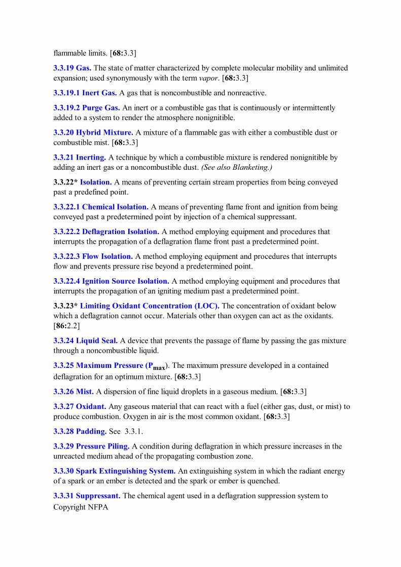
3.3.19 Gas. The state of matter characterized by complete molecular mobility and unlimited expansion; used synonymously with the term vapor. [68:3.3]
3.3.19.1 Inert Gas. A gas that is noncombustible and nonreactive.
3.3.19.2 Purge Gas. An inert or a combustible gas that is continuously or intermittently added to a system to render the atmosphere nonignitible.
3.3.20 Hybrid Mixture. A mixture of a flammable gas with either a combustible dust or combustible mist. [68:3.3]
3.3.21 Inerting. A technique by which a combustible mixture is rendered nonignitible by adding an inert gas or a noncombustible dust. (See also Blanketing.)
3.3.22* Isolation. A means of preventing certain stream properties from being conveyed past a predefined point.
3.3.22.1 Chemical Isolation. A means of preventing flame front and ignition from being conveyed past a predetermined point by injection of a chemical suppressant.
3.3.22.2 Deflagration Isolation. A method employing equipment and procedures that interrupts the propagation of a deflagration flame front past a predetermined point.
3.3.22.3 Flow Isolation. A method employing equipment and procedures that interrupts flow and prevents pressure rise beyond a predetermined point.
3.3.22.4 Ignition Source Isolation. A method employing equipment and procedures that interrupts the propagation of an igniting medium past a predetermined point.
3.3.23* Limiting Oxidant Concentration (LOC). The concentration of oxidant below which a deflagration cannot occur. Materials other than oxygen can act as the oxidants. [86:2.2]
3.3.24 Liquid Seal. A device that prevents the passage of flame by passing the gas mixture through a noncombustible liquid.
3.3.25 Maximum Pressure (P max ). The maximum pressure developed in a contained deflagration for an optimum mixture. [68:3.3]
3.3.26 Mist. A dispersion of fine liquid droplets in a gaseous medium. [68:3.3]
3.3.27 Oxidant. Any gaseous material that can react with a fuel (either gas, dust, or mist) to produce combustion. Oxygen in air is the most common oxidant. [68:3.3]
3.3.28 Padding. See 3.3.1.
3.3.29 Pressure Piling. A condition during deflagration in which pressure increases in the unreacted medium ahead of the propagating combustion zone.
3.3.30 Spark Extinguishing System. An extinguishing system in which the radiant energy of a spark or an ember is detected and the spark or ember is quenched.
3.3.31 Suppressant. The chemical agent used in a deflagration suppression system to
Copyright NFPA
extinguish the deflagration.
3.3.32 Vapor. See 3.3.19.
3.3.33 Ventilation. The changing of an atmosphere of any space by natural or mechanical means.
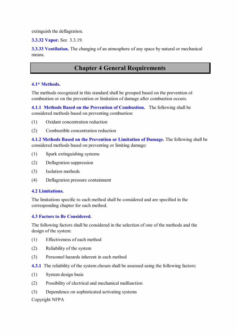
Chapter 4 General Requirements
4.1* Methods.
The methods recognized in this standard shall be grouped based on the prevention of combustion or on the prevention or limitation of damage after combustion occurs.
4.1.1 Methods Based on the Prevention of Combustion. The following shall be considered methods based on preventing combustion:
(1) Oxidant concentration reduction
(2) Combustible concentration reduction
4.1.2 Methods Based on the Prevention or Limitation of Damage. The following shall be considered methods based on preventing or limiting damage:
(1) Spark extinguishing systems
(2) Deflagration suppression
(3) Isolation methods
(4) Deflagration pressure containment
4.2 Limitations.
The limitations specific to each method shall be considered and are specified in the corresponding chapter for each method.
4.3 Factors to Be Considered.
The following factors shall be considered in the selection of one of the methods and the design of the system:
(1) Effectiveness of each method
(2) Reliability of the system
(3) Personnel hazards inherent in each method
4.3.1 The reliability of the system chosen shall be assessed using the following factors:
(1) System design basis
(2) Possibility of electrical and mechanical malfunction
(3) Dependence on sophisticated activating systems

Copyright NFPA
(4) Need for special installation, training, operating, testing, and maintenance procedures
(5) Further limitations as presented in each chapter
4.3.2 In general, explosion prevention systems shall be used to protect processing, storage, and materials handling equipment.
4.3.3 When explosion prevention techniques are applied to rooms, buildings, or other enclosures where personnel are present, consideration shall be given to the safety of the personnel.
4.4 Plans.
4.4.1 Plans, system specifications, and manufacturer's recommendations for testing and maintenance shall contain information that enables the authority having jurisdiction to evaluate the explosion hazard and the effectiveness of the system.
4.4.2 Details of the plans shall include the following:
(1) Pertinent chemical and physical characteristics of the materials involved
(2) Location of hazards
(3) Enclosures or limits and isolation of the hazards
(4) Exposures to the hazards
4.5 Acceptance Test.
All new system installations and modifications shall be tested or otherwise evaluated to confirm the operational integrity of the system.
4.5.1 Tests shall be in accordance with the manufacturer's recommendations.
4.5.2 A written report of the tests shall be provided to the users.
4.6* Inspection and Maintenance.
4.6.1* All systems shall be inspected for operability in accordance with the manufacturer's recommendations.
4.6.2 An inspection and preventive maintenance schedule shall be established in accordance with the manufacturer's recommendations.
Chapter 5 Deflagration Prevention by Oxidant Concentration Reduction
5.1 Application.
The technique for oxidant concentration reduction for deflagration prevention shall be permitted to be considered where a mixture of oxidant and flammable material is confined to an enclosure within which the oxidant concentration can be controlled.
Copyright NFPA
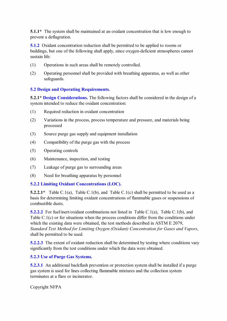
5.1.1* The system shall be maintained at an oxidant concentration that is low enough to prevent a deflagration.
5.1.2 Oxidant concentration reduction shall be permitted to be applied to rooms or buildings, but one of the following shall apply, since oxygendeficient atmospheres cannot sustain life:
(1) Operations in such areas shall be remotely controlled.
(2) Operating personnel shall be provided with breathing apparatus, as well as other safeguards.
5.2 Design and Operating Requirements.
5.2.1* Design Considerations. The following factors shall be considered in the design of a system intended to reduce the oxidant concentration:
(1) Required reduction in oxidant concentration
(2) Variations in the process, process temperature and pressure, and materials being processed
(3) Source purge gas supply and equipment installation
(4) Compatibility of the purge gas with the process
(5) Operating controls
(6) Maintenance, inspection, and testing
(7) Leakage of purge gas to surrounding areas
(8) Need for breathing apparatus by personnel
5.2.2 Limiting Oxidant Concentrations (LOC).
5.2.2.1* Table C.1(a), Table C.1(b), and Table C.1(c) shall be permitted to be used as a basis for determining limiting oxidant concentrations of flammable gases or suspensions of combustible dusts.
5.2.2.2 For fuel/inert/oxidant combinations not listed in Table C.1(a), Table C.1(b), and Table C.1(c) or for situations when the process conditions differ from the conditions under which the existing data were obtained, the test methods described in ASTM E 2079, Standard Test Method for Limiting Oxygen (Oxidant) Concentration for Gases and Vapors, shall be permitted to be used.
5.2.2.3 The extent of oxidant reduction shall be determined by testing where conditions vary significantly from the test conditions under which the data were obtained.
5.2.3 Use of Purge Gas Systems.
5.2.3.1 An additional backflash prevention or protection system shall be installed if a purge gas system is used for lines collecting flammable mixtures and the collection system terminates at a flare or incinerator.
Copyright NFPA
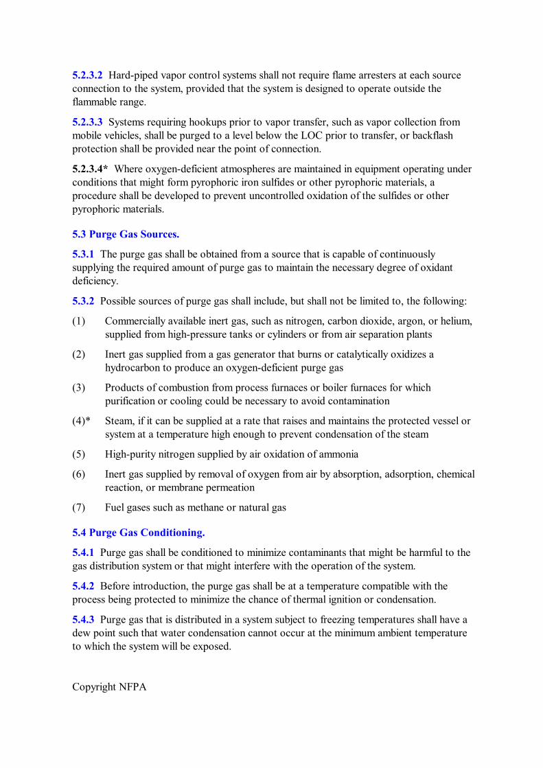
5.2.3.2 Hardpiped vapor control systems shall not require flame arresters at each source connection to the system, provided that the system is designed to operate outside the flammable range.
5.2.3.3 Systems requiring hookups prior to vapor transfer, such as vapor collection from mobile vehicles, shall be purged to a level below the LOC prior to transfer, or backflash protection shall be provided near the point of connection.
5.2.3.4* Where oxygendeficient atmospheres are maintained in equipment operating under conditions that might form pyrophoric iron sulfides or other pyrophoric materials, a procedure shall be developed to prevent uncontrolled oxidation of the sulfides or other pyrophoric materials.
5.3 Purge Gas Sources.
5.3.1 The purge gas shall be obtained from a source that is capable of continuously supplying the required amount of purge gas to maintain the necessary degree of oxidant deficiency.
5.3.2 Possible sources of purge gas shall include, but shall not be limited to, the following:
(1) Commercially available inert gas, such as nitrogen, carbon dioxide, argon, or helium, supplied from highpressure tanks or cylinders or from air separation plants
(2) Inert gas supplied from a gas generator that burns or catalytically oxidizes a hydrocarbon to produce an oxygendeficient purge gas
(3) Products of combustion from process furnaces or boiler furnaces for which purification or cooling could be necessary to avoid contamination
(4)* Steam, if it can be supplied at a rate that raises and maintains the protected vessel or system at a temperature high enough to prevent condensation of the steam
(5) Highpurity nitrogen supplied by air oxidation of ammonia
(6) Inert gas supplied by removal of oxygen from air by absorption, adsorption, chemical reaction, or membrane permeation
(7) Fuel gases such as methane or natural gas
5.4 Purge Gas Conditioning.
5.4.1 Purge gas shall be conditioned to minimize contaminants that might be harmful to the gas distribution system or that might interfere with the operation of the system.
5.4.2 Before introduction, the purge gas shall be at a temperature compatible with the process being protected to minimize the chance of thermal ignition or condensation.
5.4.3 Purge gas that is distributed in a system subject to freezing temperatures shall have a dew point such that water condensation cannot occur at the minimum ambient temperature to which the system will be exposed.
Copyright NFPA
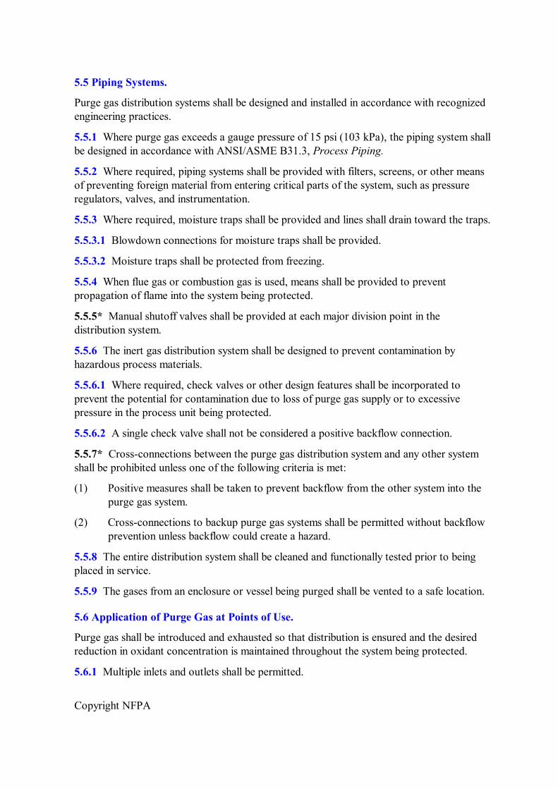
5.5 Piping Systems.
Purge gas distribution systems shall be designed and installed in accordance with recognized engineering practices.
5.5.1 Where purge gas exceeds a gauge pressure of 15 psi (103 kPa), the piping system shall be designed in accordance with ANSI/ASME B31.3, Process Piping.
5.5.2 Where required, piping systems shall be provided with filters, screens, or other means of preventing foreign material from entering critical parts of the system, such as pressure regulators, valves, and instrumentation.
5.5.3 Where required, moisture traps shall be provided and lines shall drain toward the traps.
5.5.3.1 Blowdown connections for moisture traps shall be provided.
5.5.3.2 Moisture traps shall be protected from freezing.
5.5.4 When flue gas or combustion gas is used, means shall be provided to prevent propagation of flame into the system being protected.
5.5.5* Manual shutoff valves shall be provided at each major division point in the distribution system.
5.5.6 The inert gas distribution system shall be designed to prevent contamination by hazardous process materials.
5.5.6.1 Where required, check valves or other design features shall be incorporated to prevent the potential for contamination due to loss of purge gas supply or to excessive pressure in the process unit being protected.
5.5.6.2 A single check valve shall not be considered a positive backflow connection.
5.5.7* Crossconnections between the purge gas distribution system and any other system shall be prohibited unless one of the following criteria is met:
(1) Positive measures shall be taken to prevent backflow from the other system into the purge gas system.
(2) Crossconnections to backup purge gas systems shall be permitted without backflow prevention unless backflow could create a hazard.
5.5.8 The entire distribution system shall be cleaned and functionally tested prior to being placed in service.
5.5.9 The gases from an enclosure or vessel being purged shall be vented to a safe location.
5.6 Application of Purge Gas at Points of Use.
Purge gas shall be introduced and exhausted so that distribution is ensured and the desired reduction in oxidant concentration is maintained throughout the system being protected.
5.6.1 Multiple inlets and outlets shall be permitted.
Copyright NFPA
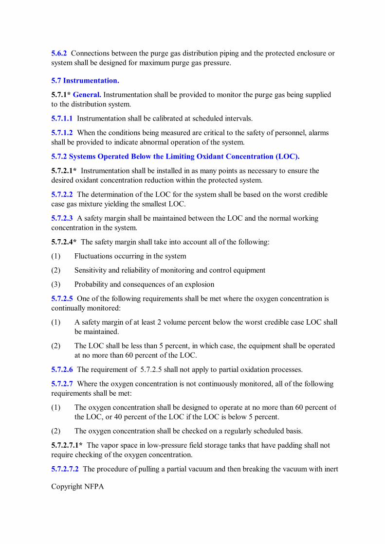
5.6.2 Connections between the purge gas distribution piping and the protected enclosure or system shall be designed for maximum purge gas pressure.
5.7 Instrumentation.
5.7.1* General. Instrumentation shall be provided to monitor the purge gas being supplied to the distribution system.
5.7.1.1 Instrumentation shall be calibrated at scheduled intervals.
5.7.1.2 When the conditions being measured are critical to the safety of personnel, alarms shall be provided to indicate abnormal operation of the system.
5.7.2 Systems Operated Below the Limiting Oxidant Concentration (LOC).
5.7.2.1* Instrumentation shall be installed in as many points as necessary to ensure the desired oxidant concentration reduction within the protected system.
5.7.2.2 The determination of the LOC for the system shall be based on the worst credible case gas mixture yielding the smallest LOC.
5.7.2.3 A safety margin shall be maintained between the LOC and the normal working concentration in the system.
5.7.2.4* The safety margin shall take into account all of the following:
(1) Fluctuations occurring in the system
(2) Sensitivity and reliability of monitoring and control equipment
(3) Probability and consequences of an explosion
5.7.2.5 One of the following requirements shall be met where the oxygen concentration is continually monitored:
(1) A safety margin of at least 2 volume percent below the worst credible case LOC shall be maintained.
(2) The LOC shall be less than 5 percent, in which case, the equipment shall be operated at no more than 60 percent of the LOC.
5.7.2.6 The requirement of 5.7.2.5 shall not apply to partial oxidation processes.
5.7.2.7 Where the oxygen concentration is not continuously monitored, all of the following requirements shall be met:
(1) The oxygen concentration shall be designed to operate at no more than 60 percent of the LOC, or 40 percent of the LOC if the LOC is below 5 percent.
(2) The oxygen concentration shall be checked on a regularly scheduled basis.
5.7.2.7.1* The vapor space in lowpressure field storage tanks that have padding shall not require checking of the oxygen concentration.
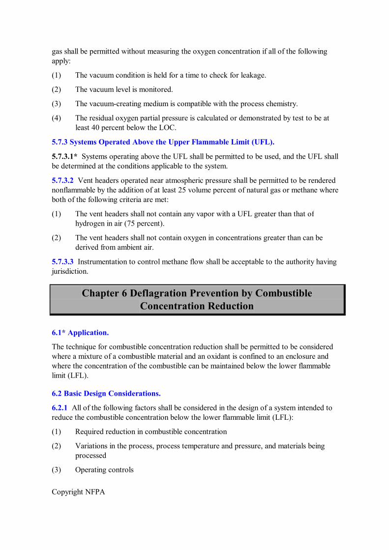
5.7.2.7.2 The procedure of pulling a partial vacuum and then breaking the vacuum with inert
Copyright NFPA
gas shall be permitted without measuring the oxygen concentration if all of the following apply:
(1) The vacuum condition is held for a time to check for leakage.
(2) The vacuum level is monitored.
(3) The vacuumcreating medium is compatible with the process chemistry.
(4) The residual oxygen partial pressure is calculated or demonstrated by test to be at least 40 percent below the LOC.
5.7.3 Systems Operated Above the Upper Flammable Limit (UFL).
5.7.3.1* Systems operating above the UFL shall be permitted to be used, and the UFL shall be determined at the conditions applicable to the system.
5.7.3.2 Vent headers operated near atmospheric pressure shall be permitted to be rendered nonflammable by the addition of at least 25 volume percent of natural gas or methane where both of the following criteria are met:
(1) The vent headers shall not contain any vapor with a UFL greater than that of hydrogen in air (75 percent).
(2) The vent headers shall not contain oxygen in concentrations greater than can be derived from ambient air.
5.7.3.3 Instrumentation to control methane flow shall be acceptable to the authority having jurisdiction.
Chapter 6 Deflagration Prevention by Combustible Concentration Reduction
6.1* Application.
The technique for combustible concentration reduction shall be permitted to be considered where a mixture of a combustible material and an oxidant is confined to an enclosure and where the concentration of the combustible can be maintained below the lower flammable limit (LFL).
6.2 Basic Design Considerations.
6.2.1 All of the following factors shall be considered in the design of a system intended to reduce the combustible concentration below the lower flammable limit (LFL):
(1) Required reduction in combustible concentration
(2) Variations in the process, process temperature and pressure, and materials being processed
(3) Operating controls
Copyright NFPA
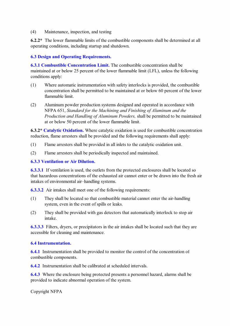
(4) Maintenance, inspection, and testing
6.2.2* The lower flammable limits of the combustible components shall be determined at all operating conditions, including startup and shutdown.
6.3 Design and Operating Requirements.
6.3.1 Combustible Concentration Limit. The combustible concentration shall be maintained at or below 25 percent of the lower flammable limit (LFL), unless the following conditions apply:
(1) Where automatic instrumentation with safety interlocks is provided, the combustible concentration shall be permitted to be maintained at or below 60 percent of the lower flammable limit.
(2) Aluminum powder production systems designed and operated in accordance with NFPA 651, Standard for the Machining and Finishing of Aluminum and the Production and Handling of Aluminum Powders, shall be permitted to be maintained at or below 50 percent of the lower flammable limit.
6.3.2* Catalytic Oxidation. Where catalytic oxidation is used for combustible concentration reduction, flame arresters shall be provided and the following requirements shall apply:
(1) Flame arresters shall be provided in all inlets to the catalytic oxidation unit.
(2) Flame arresters shall be periodically inspected and maintained.
6.3.3 Ventilation or Air Dilution.
6.3.3.1 If ventilation is used, the outlets from the protected enclosures shall be located so that hazardous concentrations of the exhausted air cannot enter or be drawn into the fresh air intakes of environmental air–handling systems.
6.3.3.2 Air intakes shall meet one of the following requirements:
(1) They shall be located so that combustible material cannot enter the airhandling system, even in the event of spills or leaks.
(2) They shall be provided with gas detectors that automatically interlock to stop air intake.
6.3.3.3 Filters, dryers, or precipitators in the air intakes shall be located such that they are accessible for cleaning and maintenance.
6.4 Instrumentation.
6.4.1 Instrumentation shall be provided to monitor the control of the concentration of combustible components.
6.4.2 Instrumentation shall be calibrated at scheduled intervals.
6.4.3 Where the enclosure being protected presents a personnel hazard, alarms shall be provided to indicate abnormal operation of the system.
Copyright NFPA
Chapter 7 Deflagration Prevention by Hot Particle Detection and Intervention Systems
7.1 Application.
Spark extinguishing systems shall be permitted to be considered for reducing the frequency of deflagrations in transport and receiving systems that handle combustible particulate solids.
7.1.1 Spark detection and extinguishing shall be used in conjunction with other explosion prevention or explosion protection measures, such as deflagration suppression or deflagration venting, for those systems posing a dust explosion hazard.
7.1.2 Spark extinguishing systems shall be used for the detection and extinguishment of sparks or embers as they pass through ducts that transport combustible dusts or solids.
7.1.3 The spark extinguishing system shall operate by means of detectors that sense the radiation from a hot or glowing particle and actuate a special extinguishing system that quenches the particle.
7.1.4 Because the detection is by means of radiation, spark detection systems shall not be used in duct systems that have openings through which incident light could affect the detectors, unless the detectors are designed to be insensitive to visible light.
7.2 Limitations.
7.2.1 Spark extinguishing systems shall not be used for ducts designed to transport flammable gases.
7.2.2 Spark extinguishing systems shall not be used where the extinguishing agent creates a hazard.
7.2.3* Spark detection and spark extinguishing systems shall be limited to the detection and extinguishment of sparks or embers traveling at the system transport velocity.
7.2.4 Spark detection and spark extinguishing systems shall not be used in extinguishing deflagration flame fronts or flow isolation.
7.3 Spark Detection and Spark Extinguishing System Design Considerations.
7.3.1* General. Spark detection and spark extinguishing systems shall be listed or approved.
7.3.2 Detectors.
7.3.2.1 Spacing between a detector and the extinguishing agent injection point shall be based on all of the following:
(1) Linear velocity of the material in the duct
(2) Response time of the detector
(3) Actuator circuitry.
Copyright NFPA
7.3.2.2 The number of detectors shall be sufficient to detect a glowing particle at any location in the crosssectional area of the duct.
7.3.2.3 Provisions shall be made to prevent obscuration of radiant energy detectors.
7.3.2.4 Detectors shall be protected from the accumulation of foreign material that would prevent functioning.
7.3.3 Power/Control Units.
7.3.3.1 A power/control unit with a minimum 24hour standby battery backup shall be provided with each suppression system and shall supply energy to accomplish all of the following:
(1) Power all detection devices
(2) Energize all electrically actuated extinguishing systems
(3) Energize visual and audible alarms
(4) Transfer all auxiliary control and alarm contacts
(5) Control systemdisabling interlock and process shutdown circuits
7.3.3.2 The power/control unit shall meet the applicable requirements of 1.5.2 and Chapter 3 of NFPA 72, National Fire Alarm Code ® .
7.3.3.3 The power/control unit shall, as a minimum, fully and continuously supervise all of the following:
(1) Wiring circuits for opens and other faults
(2) AC power supply (primary)
(3) Battery voltage, presence, and polarity
(4) System safety interlock circuitry
(5) Systemdisabling interlock circuitry
(6) Releasing outputs
(7) Electrical extinguishing actuators
(8) Detectors
(9) Visible and audible alarms
(10) Circuit ground fault
7.3.3.4 In addition to noncritical trouble alarms, the power/control unit shall have separate contacts capable of initiating an orderly shutdown of the protected process upon receipt of any trouble signal that indicates a disabled protection system.
7.3.3.5 The supervisory signal circuits shall be provided with a visual and audible trouble signal.
Copyright NFPA
7.3.4 Extinguishing System.
7.3.4.1 Discharge nozzles shall be located and arranged so that solid particles cannot obstruct the nozzles.
7.3.4.2 If water is used as the extinguishing agent, the water supply system shall be equipped with an inline strainer.
7.3.4.3 The extinguishing agent supply system shall be capable of supplying all discharge nozzles at the rated volume and pressure.
7.3.4.4 The system shall contain enough extinguishing agent to provide for no less than 100 operations of the system.
7.3.4.5 An alarm shall sound when the pressure of the extinguishing agent falls below the minimum supply pressure specified by the manufacturer.
7.3.4.6 Auxiliary heating systems for extinguishing agent storage shall be provided, when necessary, and shall comply with all of the following:
(1) The temperature of the extinguishing agent shall be supervised.
(2) An alarm shall sound at both the low and high temperature limits.
7.3.5 Other Intervention Systems. Other intervention systems, including the following, shall be permitted to be actuated by the optical detection system:
(1) Water deluge
(2) Carbon dioxide flooding
(3) Automatic fastacting valves
(4) Diverting valves
(5) Steam snuffing
7.4 Testing.
A functional test of the extinguishing portion of the system shall be conducted in accordance with the manufacturer's specifications.
7.5 Spark Detection and Spark Extinguishing System Inspection and Maintenance.
Spark extinguishing systems shall be inspected and maintained in accordance with the manufacturer's recommendations.
7.5.1 A written report on the most recent inspection shall be kept on file for review.
7.5.2 The report shall include test and calibration data on all system components.
Chapter 8 Deflagration Control by Suppression
Copyright NFPA
8.1 Application.
8.1.1 The technique for deflagration suppression shall be permitted to be considered for most flammable gases, combustible mists, or combustible dusts that are subject to deflagration in a gas phase oxidant.
8.1.2 Enclosures that can be protected by a deflagration suppression system shall include, but shall not be limited to, the following:
(1) Processing equipment, such as reactor vessels, mixers, blenders, pulverizers, mills, dryers, ovens, filters, screens, and dust collectors
(2) Storage equipment, such as atmospheric or lowpressure tanks, pressure tanks, and mobile facilities
(3) Materialhandling equipment, such as pneumatic and screw conveyors and bucket elevators
(4) Laboratory and pilot plant equipment, including hoods, glove boxes, test cells, and other equipment
(5) Aerosol filling rooms
8.2 Limitations.
8.2.1 Deflagration suppression is successful only where the suppressant can be distributed during the early stages of flame development.
8.2.2 Deflagration suppression is limited by the physical and chemical properties of the reactants in the system, as well as the design and construction of the enclosure.
8.2.3 The strength of the protected enclosure shall be greater than the maximum suppressed deflagration pressure (including effects of suppressant discharge).
8.3 Personnel Safety.
8.3.1* Disarming and Lockout/Tagout Procedures.
8.3.1.1 Disarming and lockout/tagout procedures shall be followed prior to entering equipment protected by deflagration suppression systems.
8.3.1.2 The deflagration suppression system shall be disarmed prior to performing maintenance operations on the protected equipment if discharging the suppressant could result in injury.
8.3.1.3 Operation of the protected equipment shall be interlocked through the suppression system control panel so that operation cannot be resumed until the suppression system is armed.
8.3.2 Training. Personnel shall be trained in the safety procedures that are to be carried out prior to, during, and after maintenance.
8.4 Basic Design Considerations.
Copyright NFPA
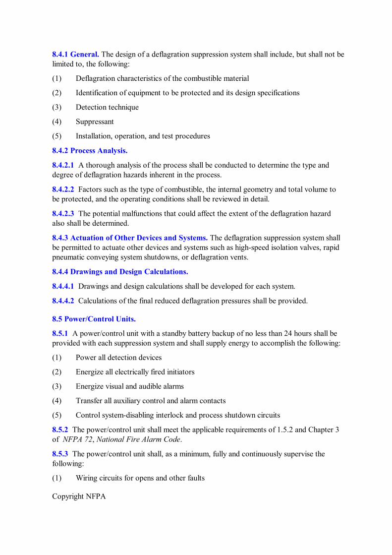
8.4.1 General. The design of a deflagration suppression system shall include, but shall not be limited to, the following:
(1) Deflagration characteristics of the combustible material
(2) Identification of equipment to be protected and its design specifications
(3) Detection technique
(4) Suppressant
(5) Installation, operation, and test procedures
8.4.2 Process Analysis.
8.4.2.1 A thorough analysis of the process shall be conducted to determine the type and degree of deflagration hazards inherent in the process.
8.4.2.2 Factors such as the type of combustible, the internal geometry and total volume to be protected, and the operating conditions shall be reviewed in detail.
8.4.2.3 The potential malfunctions that could affect the extent of the deflagration hazard also shall be determined.
8.4.3 Actuation of Other Devices and Systems. The deflagration suppression system shall be permitted to actuate other devices and systems such as highspeed isolation valves, rapid pneumatic conveying system shutdowns, or deflagration vents.
8.4.4 Drawings and Design Calculations.
8.4.4.1 Drawings and design calculations shall be developed for each system.
8.4.4.2 Calculations of the final reduced deflagration pressures shall be provided.
8.5 Power/Control Units.
8.5.1 A power/control unit with a standby battery backup of no less than 24 hours shall be provided with each suppression system and shall supply energy to accomplish the following:
(1) Power all detection devices
(2) Energize all electrically fired initiators
(3) Energize visual and audible alarms
(4) Transfer all auxiliary control and alarm contacts
(5) Control systemdisabling interlock and process shutdown circuits
8.5.2 The power/control unit shall meet the applicable requirements of 1.5.2 and Chapter 3 of NFPA 72, National Fire Alarm Code.
8.5.3 The power/control unit shall, as a minimum, fully and continuously supervise the following:
(1) Wiring circuits for opens and other faults
Copyright NFPA
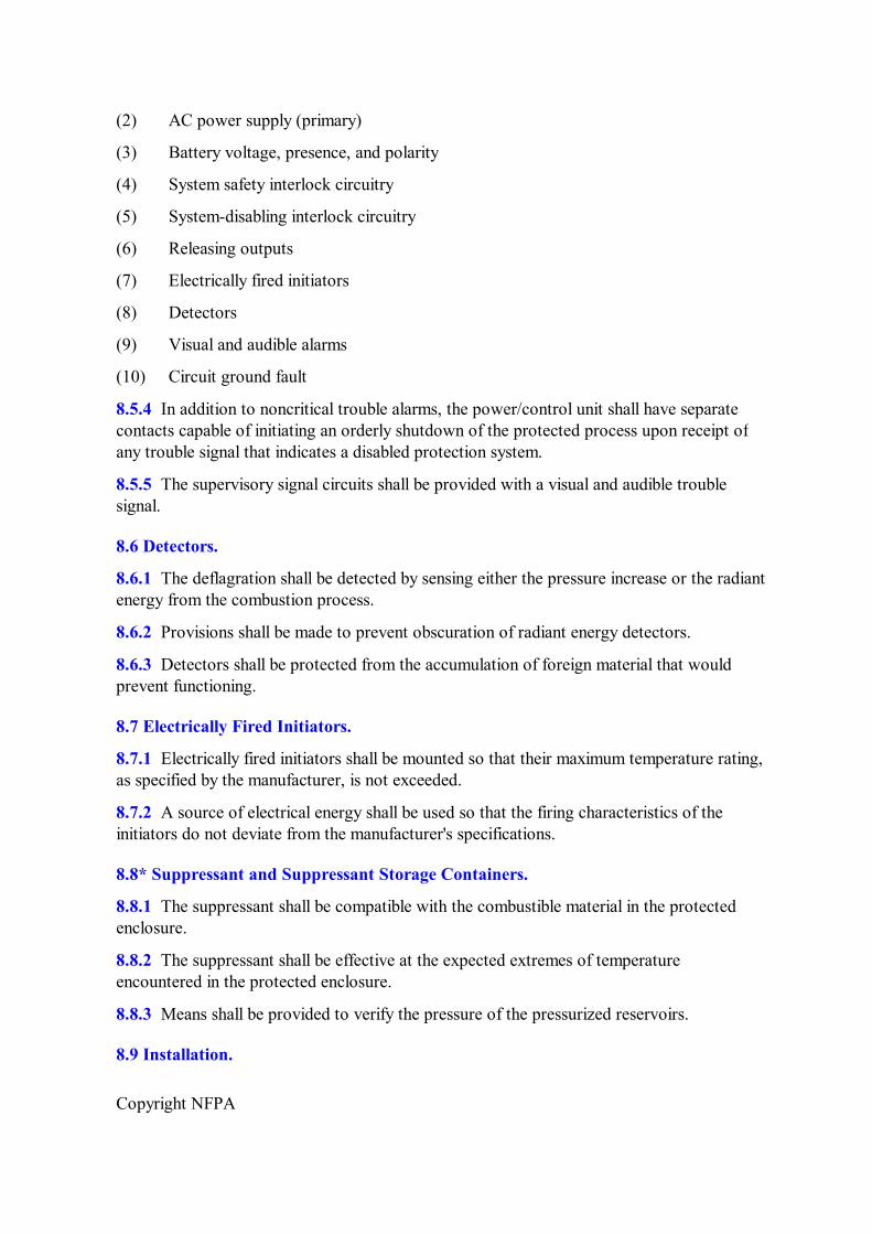
(2) AC power supply (primary)
(3) Battery voltage, presence, and polarity
(4) System safety interlock circuitry
(5) Systemdisabling interlock circuitry
(6) Releasing outputs
(7) Electrically fired initiators
(8) Detectors
(9) Visual and audible alarms
(10) Circuit ground fault
8.5.4 In addition to noncritical trouble alarms, the power/control unit shall have separate contacts capable of initiating an orderly shutdown of the protected process upon receipt of any trouble signal that indicates a disabled protection system.
8.5.5 The supervisory signal circuits shall be provided with a visual and audible trouble signal.
8.6 Detectors.
8.6.1 The deflagration shall be detected by sensing either the pressure increase or the radiant energy from the combustion process.
8.6.2 Provisions shall be made to prevent obscuration of radiant energy detectors.
8.6.3 Detectors shall be protected from the accumulation of foreign material that would prevent functioning.
8.7 Electrically Fired Initiators.
8.7.1 Electrically fired initiators shall be mounted so that their maximum temperature rating, as specified by the manufacturer, is not exceeded.
8.7.2 A source of electrical energy shall be used so that the firing characteristics of the initiators do not deviate from the manufacturer's specifications.
8.8* Suppressant and Suppressant Storage Containers.
8.8.1 The suppressant shall be compatible with the combustible material in the protected enclosure.
8.8.2 The suppressant shall be effective at the expected extremes of temperature encountered in the protected enclosure.
8.8.3 Means shall be provided to verify the pressure of the pressurized reservoirs.
8.9 Installation.
Copyright NFPA
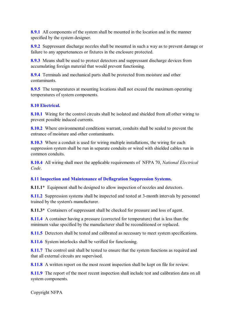
8.9.1 All components of the system shall be mounted in the location and in the manner specified by the system designer.
8.9.2 Suppressant discharge nozzles shall be mounted in such a way as to prevent damage or failure to any appurtenances or fixtures in the enclosure protected.
8.9.3 Means shall be used to protect detectors and suppressant discharge devices from accumulating foreign material that would prevent functioning.
8.9.4 Terminals and mechanical parts shall be protected from moisture and other contaminants.
8.9.5 The temperatures at mounting locations shall not exceed the maximum operating temperatures of system components.
8.10 Electrical.
8.10.1 Wiring for the control circuits shall be isolated and shielded from all other wiring to prevent possible induced currents.
8.10.2 Where environmental conditions warrant, conduits shall be sealed to prevent the entrance of moisture and other contaminants.
8.10.3 Where a conduit is used for wiring multiple installations, the wiring for each suppression system shall be run in separate conduits or wired with shielded cables run in common conduits.
8.10.4 All wiring shall meet the applicable requirements of NFPA 70, National Electrical Code.
8.11 Inspection and Maintenance of Deflagration Suppression Systems.
8.11.1* Equipment shall be designed to allow inspection of nozzles and detectors.
8.11.2 Suppression systems shall be inspected and tested at 3month intervals by personnel trained by the system's manufacturer.
8.11.3* Containers of suppressant shall be checked for pressure and loss of agent.
8.11.4 A container having a pressure (corrected for temperature) that is less than the minimum value specified by the manufacturer shall be reconditioned or replaced.
8.11.5 Detectors shall be tested and calibrated as necessary to meet system specifications.
8.11.6 System interlocks shall be verified for functioning.
8.11.7 The control unit shall be tested to ensure that the system functions as required and that all external circuits are supervised.
8.11.8 A written report on the most recent inspection shall be kept on file for review.
8.11.9 The report of the most recent inspection shall include test and calibration data on all system components.
Copyright NFPA
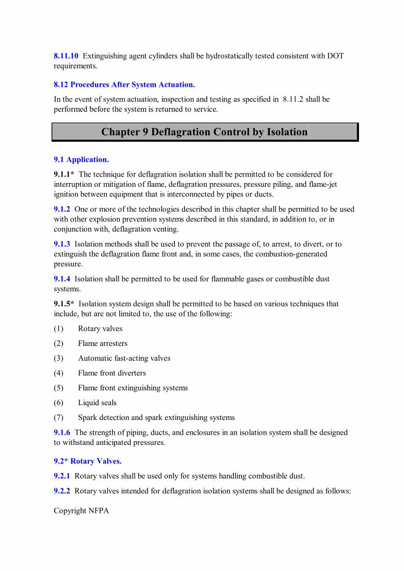
8.11.10 Extinguishing agent cylinders shall be hydrostatically tested consistent with DOT requirements.
8.12 Procedures After System Actuation.
In the event of system actuation, inspection and testing as specified in 8.11.2 shall be performed before the system is returned to service.
Chapter 9 Deflagration Control by Isolation
9.1 Application.
9.1.1* The technique for deflagration isolation shall be permitted to be considered for interruption or mitigation of flame, deflagration pressures, pressure piling, and flamejet ignition between equipment that is interconnected by pipes or ducts.
9.1.2 One or more of the technologies described in this chapter shall be permitted to be used with other explosion prevention systems described in this standard, in addition to, or in conjunction with, deflagration venting.
9.1.3 Isolation methods shall be used to prevent the passage of, to arrest, to divert, or to extinguish the deflagration flame front and, in some cases, the combustiongenerated pressure.
9.1.4 Isolation shall be permitted to be used for flammable gases or combustible dust systems.
9.1.5* Isolation system design shall be permitted to be based on various techniques that include, but are not limited to, the use of the following:
(1) Rotary valves
(2) Flame arresters
(3) Automatic fastacting valves
(4) Flame front diverters
(5) Flame front extinguishing systems
(6) Liquid seals
(7) Spark detection and spark extinguishing systems
9.1.6 The strength of piping, ducts, and enclosures in an isolation system shall be designed to withstand anticipated pressures.
9.2* Rotary Valves.
9.2.1 Rotary valves shall be used only for systems handling combustible dust.
9.2.2 Rotary valves intended for deflagration isolation systems shall be designed as follows:
Copyright NFPA
(1) A clearance that is small enough to prevent the passage of flame shall be provided between the rotor and the valve housing.
(2) At least two vanes on each side of the valve housing shall be in a position of minimum clearance at all times.
9.2.3 Rotary valves shall be capable of withstanding the maximum expected pressure.
9.2.4* Rotary valves intended for deflagration isolation systems shall have metal bodies and vanes unless it is shown by test data that nonmetallic or composite materials prevent flame passage.
9.3* Flame Arresters.
9.3.1 Section 9.3 shall not apply to the following:
(1) Devices that utilize a liquid seal to prevent the passage of flame
(2) Devices that rely on gas flow velocity to prevent upstream propagation of flame
(3) Systems handling combustible dusts
9.3.2* Flame arresters shall be placed in the potential flame path between the source of ignition and the system to be protected.
9.3.3 Flame arresters shall be installed in accordance with the manufacturer's instructions.
9.3.4* Flame arresters for inline use shall be tested for such an application.
9.3.5* An inline arrester that experiences continued burning for a time longer than that for which it was tested shall meet the following criteria:
(1) A means of detecting the burning shall be provided on both sides of the arrester along with an alarm or automatic device to interrupt flow prior to failure.
(2) If thermocouples are used, they shall not be placed in thermowells.
9.3.6* Arresters shall be inspected periodically, based on facility experience, and after each incident where they have been called upon to function.
9.3.6.1 The inspection shall determine whether any damage has occurred that could affect the performance of the device.
9.3.6.2 Damaged components shall be replaced.
9.4* Automatic FastActing Valve Systems.
9.4.1 Automatic fastacting valve systems shall be designed to detect a deflagration and to prevent propagation of flame and combustiongenerated pressure beyond the fastacting valves by providing a positive mechanical seal.
9.4.2 Factors that affect the performance of fastacting automaticclosing valves shall be considered in the design and applications and shall include, but not be limited to, the following:
Copyright NFPA
(1) Deflagration characteristics of the combustible material
(2) Volume, configuration, and operating characteristics of the vessel
(3) Type of deflagration protection used on the vessel and piping
(4) Volume, length, crosssectional area, configuration, and strength of the piping
(5) Velocity of the combustible air mixture in the pipe
(6) Location of system components
(7) Closure time of the valve, including control and detection components
(8) Detection technique
9.4.3 Fastacting valves and deflagration detectors shall be capable of withstanding the maximum expected deflagration pressures, including pressure piling.
9.4.4* The fastacting valve systems shall be of a design that has been tested under deflagration conditions to verify their performance.
9.4.5 Spacing between a detector and the fastacting valve shall be based on the maximum flame speed expected in the duct and the response time of the detector, the valve, and the actuator circuitry.
9.4.6 The diameter of the pipe leading to the automatic fastacting valve shall not be decreased, unless the automatic fastacting valve has been specifically tested for the configuration.
9.4.7 Personnel shall be trained in the safety procedures that are to be carried out prior to, during, and after maintenance.
9.4.8 A power/control unit with a minimum 24hour standby battery backup shall be provided with each suppression system and shall supply energy to accomplish the following:
(1) Power all detection devices
(2) Energize all electrically actuated valve systems
(3) Energize visual and audible alarms
(4) Transfer all auxiliary control and alarm contacts
(5) Control system–disabling interlock and process shutdown circuits
9.4.8.1 The power/control unit shall meet the applicable requirements of 1.5.2 and Chapter 3 of NFPA 72, National Fire Alarm Code.
9.4.8.2 The power/control unit shall, as a minimum, fully and continuously supervise the following:
(1) Wiring circuits for opens and other faults
(2) AC power supply (primary)
(3) Battery voltage, presence, and polarity
Copyright NFPA
(4) System safety interlock circuitry
(5) Systemdisabling interlock circuitry
(6) Releasing outputs
(7) Electrically actuated valves
(8) Detectors
(9) Visual and audible alarms
(10) Circuit ground fault
9.4.8.3 The supervisory signal circuits shall be provided with a visual and audible trouble signal.
9.4.8.4 In addition to noncritical trouble alarms, the power/control unit shall have separate contacts capable of initiating an orderly shutdown of the protected process upon receipt of any trouble signal that indicates a disabled protection system.
9.4.9 The deflagration shall be detected by sensing either the pressure increase or the radiant energy from the combustion process.
9.4.9.1* Provisions shall be made to prevent obscuration of radiant energy detectors.
9.4.9.2 Detectors shall be protected from the accumulation of foreign material that would prevent functioning.
9.4.10 Electrically fired initiators shall be mounted so that their maximum temperature rating, as specified by the manufacturer, is not exceeded.
9.4.11 Pneumatic valve actuator systems shall comply with the following requirements:
(1) Pneumatic valve actuators shall be mounted so that their maximum temperature rating, as specified by the manufacturer, is not exceeded.
(2) Means shall be provided to verify the pressure of the pressurized reservoir for the pneumatic valve actuator.
9.4.12 Wiring for the control circuits shall be isolated and shielded from all other wiring to prevent possible induced currents.
9.4.12.1 Where environmental conditions warrant, conduits shall be sealed to prevent the entrance of moisture and other contaminants.
9.4.12.2 Where a conduit is used for wiring multiple installations, the wiring for each automatic fastacting valve system shall be run in a separate conduit. Alternatively, each system shall be permitted to be wired with shielded cables run in common conduit.
9.4.12.3 All wiring shall meet the applicable requirements of NFPA 70, National Electrical Code.
9.4.13 All components of the system shall be mounted in the location and in the manner specified by the system designer.
Copyright NFPA
9.4.13.1 Where necessary, measures shall be used to protect detectors and fastacting valves from accumulating foreign material that would prevent operation.
9.4.13.2 Terminals and mechanical parts shall be protected from moisture and other contaminants.
9.4.13.3 The temperatures at mounting locations shall not exceed the maximum operating temperatures of system components.
9.4.14 Inspection and maintenance of automatic fastacting valve systems shall comply with the following requirements:
(1) Automatic fastacting valve systems shall be inspected and maintained in accordance with the manufacturer's recommendations.
(2) Containers of suppressant shall be checked for pressure and loss of agent.
(3) A container having a pressure (corrected for temperature) that is less than the minimum value specified by the manufacturer shall be reconditioned or replaced.
(4) A written report on the most recent inspection shall be kept on file for review. The report shall include test and calibration data on all system components.
9.4.15 In the event of system actuation, inspection and testing as specified by the manufacturer shall be performed before the system is returned to service.
9.5* Flame Front Diverters.
9.5.1 Flame front diverters shall be permitted to be used as a deflagration loss control measure.
9.5.2 Flame front diverter system design considerations shall include, but not be limited to, the following:
(1) Deflagration characteristics of the combustible material
(2) Volume, configuration, and operating characteristics of the equipment to be protected and the conveying system
(3) Type of deflagration protection used on the vessel
(4) Length, crosssectional area, configuration, and strength of the piping
(5) Velocity of the combustible air mixture in the pipe
(6) Location of the flame front diverter and its associated piping
(7) Turbulencegenerating features in the piping such as fittings, valves, elbows, and wall roughness
(8) Location of probable ignition sources
9.5.3 The body design shall divert the flame front to atmosphere and away from the downstream piping.
Copyright NFPA
9.5.4 The body shall be capable of withstanding expected deflagration pressure.
9.5.5 The closure device shall be either a rupture disc or a cover plate.
9.5.6 Where the closure device could be a missile hazard, it shall be either tethered or contained in a cage.
9.5.7 The hazard of flame discharge from the flame front diverter shall be considered when designing the placement of the device.
9.5.8 The flame front diverter shall discharge to a safe, unrestricted, outdoor location.
9.5.9* Flame front diverters shall be tested for the application.
9.6 Chemical Isolation Systems.
9.6.1 General Requirements.
9.6.1.1 Chemical isolation systems shall be permitted to be used to isolate interconnected process volumes from the effects of deflagration flame passage through interconnecting pipe.
9.6.1.2 Chemical isolation systems shall be designed to detect a deflagration flame event and to cause discharge of an extinguishing agent into a length of pipe sufficient to prevent flame propagation past the point of agent discharge.
9.6.1.3 Chemical isolation system components exposed to the process environment shall be capable of withstanding the maximum expected deflagration pressure.
9.6.1.4 A chemical isolation system shall be of a design that has been tested under deflagration conditions to verify performance.
9.6.1.5 The distance between the position of a deflagration flame event detector and the associated agent discharge point shall be based on the following:
(1) Maximum deflagration flame speed expected in the pipe
(2) Response time characteristics of the detector
(3) Discharge rate from the agent containers
9.6.1.6 Chemical isolation systems shall be disarmed before maintenance operations are performed on the system components.
9.6.1.7 Personnel shall be trained in safety procedures to be carried out prior to, during, and after maintenance.
9.6.2 Detectors.
9.6.2.1 Deflagration flame event detectors shall be of the pressure sensing or radiant energy sensing type.
9.6.2.2 Provisions shall be made to prevent obscuration of radiant energy detectors.
9.6.2.3 Provisions shall be made to prevent blockage of access to the sensing surface of pressuretype detectors.
Copyright NFPA
9.6.3 Extinguishing Agent and Containers.
9.6.3.1 The extinguishing agent shall be chemically compatible with the material normally conveyed through the pipe system being protected.
9.6.3.2 The extinguishing agent shall be of a type that is effective at all temperatures to be encountered in the application.
9.6.3.3 Extinguishing agent containers, if used as shipping containers, shall be designed to meet the requirements of the U.S. Department of Transportation.
9.6.3.3.1 If not used as shipping containers, extinguishing agent containers shall be designed, fabricated, inspected, certified, and stamped in accordance with Section VIII of the ASME Boiler and Pressure Vessel Code.
9.6.3.3.2 The design pressure shall be suitable for the maximum pressure developed at 55°C (130°F) or at the maximum controlled temperature limit.
9.6.4 Electrically Fired Initiators. Electrically fired initiators shall be mounted so that their maximum temperature rating, as specified by the manufacturer, is not exceeded.
9.6.5 Power/Control Units.
9.6.5.1 A power/control unit with a minimum 24hour standby battery backup shall be provided with each chemical isolation system and shall supply energy to accomplish the following:
(1) Power all detection devices
(2) Energize all electrically actuated chemical isolation systems
(3) Energize visual and audible alarms
(4) Transfer all auxiliary control and alarm contacts
(5) Control systemdisabling interlock and process shutdown circuits
9.6.5.2 The power/control unit shall meet the applicable requirements of 1.5.2 and Chapter 3 of NFPA 72, National Fire Alarm Code.
9.6.5.3 The power/control unit shall, as a minimum, fully and continuously supervise the following:
(1) Wiring circuits for opens and other faults
(2) AC power supply (primary)
(3) Battery voltage, presence, and polarity
(4) System safety interlock circuitry
(5) Systemdisabling interlock circuitry
(6) Releasing outputs
(7) Electrical extinguishing actuators
Copyright NFPA
(8) Detectors
(9) Visual and audible alarms
(10) Circuit ground fault
9.6.5.4 The supervisory signal circuits shall be provided with a visual and audible trouble signal.
9.6.5.5 In addition to noncritical trouble alarms, the power/control unit shall have separate contacts capable of initiating an orderly shutdown of the protected process upon receipt of any trouble signal that indicates a disabled protection system.
9.6.5.6 The power and control unit shall meet applicable requirements of NFPA 70, National Electrical Code.
9.6.6 Electrical.
9.6.6.1 Wiring for the control circuits shall be isolated and shielded from all other wiring to prevent possible induced currents.
9.6.6.2 When a conduit is used for wiring multiple installations, the wiring for each chemical isolation system shall be run in separate conduit or wired with shielded cables run in common conduit.
9.6.6.3 All wiring shall meet the applicable requirements of NFPA 70, National Electrical Code.
9.6.7 Installation of Chemical Isolation Systems.
9.6.7.1 All components of the system shall be mounted in the location and in the manner specified by the system designer.
9.6.7.2 Where necessary, measures shall be used to protect detectors and extinguisher components from accumulating foreign material that would prevent operation.
9.6.7.3 Terminals and mechanical parts shall be protected from moisture and other contaminants.
9.6.7.4 The temperatures at mounting locations shall not exceed the maximum operating temperatures of system components.
9.6.8 Inspection and Maintenance of Chemical Isolation Systems.
9.6.8.1 Chemical isolation systems shall be inspected and maintained in accordance with the manufacturer's recommendations.
9.6.8.2 Containers of suppressant shall be checked for pressure and loss of agents.
9.6.8.3 A container having a pressure (corrected for temperature) that is less than the minimum value specified by the manufacturer shall be reconditioned or replaced.
9.6.8.4 A written report on the most recent inspection shall be kept on file for review.
9.6.8.5 The report shall include test and calibration data on all system components.
Copyright NFPA
9.6.9 Procedures After System Trouble or Actuation. In the event of system actuation, inspection and maintenance as specified in 9.6.8 shall be performed before the system is returned to service.
9.7* Liquid Seals.
A liquid seal shall be used for preventing the passage of flame by passing gas through a liquid.
9.7.1 Liquid seal devices shall be designed for the gases being handled at the flow velocities range in the system and to withstand the maximum anticipated deflagration pressure.
9.7.2 Liquid seals shall be designed in accordance with other recognized practices.
9.7.3* Means for providing and maintaining the liquid level shall be provided, as well as an alarm to detect malfunction.
Chapter 10 Deflagration Control by Pressure Containment
10.1 Application.
10.1.1 The technique for deflagration pressure containment shall be permitted to be considered for specifying the design pressure of a vessel and its appurtenances so they are capable of withstanding the maximum pressures resulting from an internal deflagration.
10.1.2 This chapter shall provide the basis for determining the vessel design pressure required to withstand the pressures resulting from an internal deflagration.
10.1.3 This chapter shall be limited to systems in which the oxidant is air.
10.1.4 The design pressure specified by this chapter shall be based on the most severe set of system conditions that can occur.
10.1.5* Deflagration pressure containment shall be applied to a vessel with attached equipment to protect such equipment from imposed pressure loads that could equal or be greater than the pressure loads experienced by the protected vessel.
10.2 Design Limitations.
10.2.1* Deflagration pressure containment techniques shall not be applied to systems for the purpose of containing a detonation.
10.2.2* Deflagration pressure containment shall not be applied to systems where two or more vessels are connected by largediameter pipes or ducts, unless one of the following criteria is met:
(1) Deflagration pressure containment shall be permitted to be used where interconnected piping is provided with deflagration isolation.
(2) Deflagration pressure containment shall be permitted to be used where venting is provided for interconnected piping.
Copyright NFPA
(3) Deflagration pressure containment shall be permitted to be used where interconnected vessels are designed to contain the increased pressures due to the effects of prepressurization.
(4) Deflagration isolation or venting of one vessel shall be permitted to be used.
(5) Deflagration pressure containment shall be permitted to be used for initial gauge pressures exceeding 2 bar (30 psi) only when the maximum deflagration pressure ratio (R) is determined by test or calculations.
10.2.3* The alternative of 10.2.2(5) shall not be permitted where test data are available.
10.3 Design Bases.
10.3.1 Vessels designed for deflagration pressure containment shall be designed and constructed according to Section VIII, Division 1, of the ASME Boiler and Pressure Vessel Code, which takes into consideration sources of overpressure other than deflagration.
10.3.2 The design pressure of the vessel, as calculated in 10.3.3, shall be based either on preventing rupture of the vessel (the ultimate strength of the vessel) or on preventing permanent deformation of the vessel (the yield strength of the vessel) from internal positive overpressure. Due to the vacuum that could follow a deflagration, all vessels whose deflagration pressure containment design is based on preventing deformation also shall be designed to withstand an absolute internal pressure of 68.95 kPa (10 psi), or they shall be provided with vacuum relief.
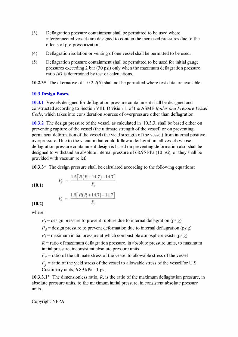
10.3.3* The design pressure shall be calculated according to the following equations:
(10.1)
(10.2)
where:
P f = design pressure to prevent rupture due to internal deflagration (psig) P d = design pressure to prevent deformation due to internal deflagration (psig) P i = maximum initial pressure at which combustible atmosphere exists (psig) R = ratio of maximum deflagration pressure, in absolute pressure units, to maximum initial pressure, inconsistent absolute pressure units F u = ratio of the ultimate stress of the vessel to allowable stress of the vessel F y = ratio of the yield stress of the vessel to allowable stress of the vesselFor U.S. Customary units, 6.89 kPa =1 psi
10.3.3.1* The dimensionless ratio, R, is the ratio of the maximum deflagration pressure, in absolute pressure units, to the maximum initial pressure, in consistent absolute pressure units.
Copyright NFPA
10.3.3.2 For use as a practical design basis (since optimum conditions seldom exist in industrial equipment), the value of R shall be as follows:
(1) For most gas/air mixtures, the value of R shall be 9.
(2) For St1 and St2 dust/air mixtures, the value of R shall be 11.
(3) For St3 dust/air mixtures, the value of R shall be 13.
10.3.3.3 A value for R other than the values specified in 10.3.3.2 shall be permitted to be used if such value can be substantiated by test data or calculations.
10.3.3.4 The vessel design pressure shall be based on the wall thickness of the vessel, excluding any allowance for corrosion or erosion.
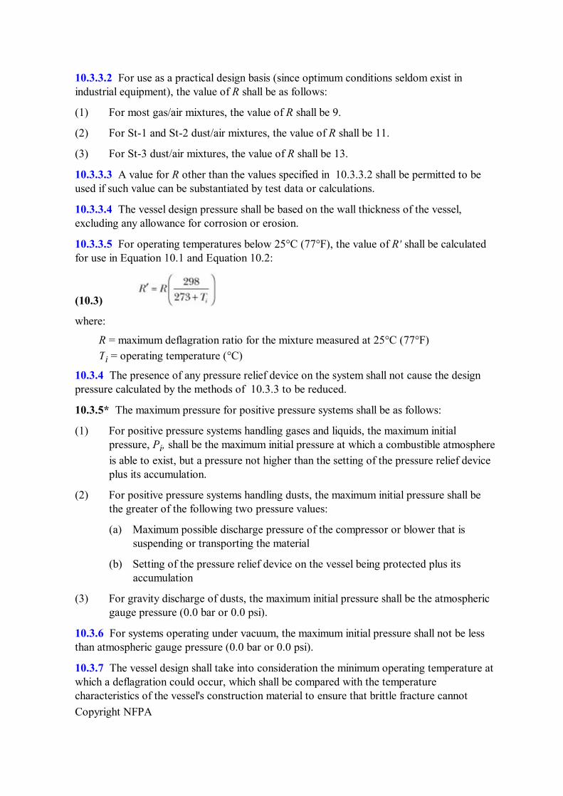
10.3.3.5 For operating temperatures below 25°C (77°F), the value of R' shall be calculated for use in Equation 10.1 and Equation 10.2:
(10.3)
where:
R = maximum deflagration ratio for the mixture measured at 25°C (77°F) T i = operating temperature (°C)
10.3.4 The presence of any pressure relief device on the system shall not cause the design pressure calculated by the methods of 10.3.3 to be reduced.
10.3.5* The maximum pressure for positive pressure systems shall be as follows:
(1) For positive pressure systems handling gases and liquids, the maximum initial pressure, P i , shall be the maximum initial pressure at which a combustible atmosphere is able to exist, but a pressure not higher than the setting of the pressure relief device plus its accumulation.
(2) For positive pressure systems handling dusts, the maximum initial pressure shall be the greater of the following two pressure values:
(a) Maximum possible discharge pressure of the compressor or blower that is suspending or transporting the material
(b) Setting of the pressure relief device on the vessel being protected plus its accumulation
(3) For gravity discharge of dusts, the maximum initial pressure shall be the atmospheric gauge pressure (0.0 bar or 0.0 psi).
10.3.6 For systems operating under vacuum, the maximum initial pressure shall not be less than atmospheric gauge pressure (0.0 bar or 0.0 psi).
10.3.7 The vessel design shall take into consideration the minimum operating temperature at which a deflagration could occur, which shall be compared with the temperature characteristics of the vessel's construction material to ensure that brittle fracture cannot
Copyright NFPA
result from a deflagration.
10.3.8 Auxiliary equipment such as vent systems, manways, fittings, and other openings into the vessel shall be designed to ensure integrity of the total system and shall be inspected periodically.
10.4 Maintenance.
Relief devices shall be inspected periodically to ensure that they are not plugged, frozen, or corroded.
10.5 Threaded Fasteners.
Threaded fasteners on vessel appurtenances shall be inspected to ensure that design pressure ratings are maintained.
10.6 Inspection After a Deflagration.
Any vessel designed to contain a deflagration that experiences a deflagration shall be inspected to verify that the vessel is still serviceable for its intended use.
Annex A Explanatory Material
Annex A is not a part of the requirements of this NFPA document but is included for informational purposes only. This annex contains explanatory material, numbered to correspond with the applicable text paragraphs.
A.1.3.2(2) For information on deflagration venting, see NFPA 68, Guide for Venting of Deflagrations.
A.1.3.2(8) For information on cutting and welding practices, see NFPA 51B, Standard for Fire Prevention During Welding, Cutting, and Other Hot Work. For information on preparation of tanks, piping, or other enclosures for hot work, see NFPA 326, Standard for the Safeguarding of Tanks and Containers for Entry, Cleaning, or Repair.
A.3.2.1 Approved. The National Fire Protection Association does not approve, inspect, or certify any installations, procedures, equipment, or materials; nor does it approve or evaluate testing laboratories. In determining the acceptability of installations, procedures, equipment, or materials, the authority having jurisdiction may base acceptance on compliance with NFPA or other appropriate standards. In the absence of such standards, said authority may require evidence of proper installation, procedure, or use. The authority having jurisdiction may also refer to the listings or labeling practices of an organization that is concerned with product evaluations and is thus in a position to determine compliance with appropriate standards for the current production of listed items.
A.3.2.2 Authority Having Jurisdiction (AHJ). The phrase “authority having jurisdiction,” or its acronym AHJ, is used in NFPA documents in a broad manner, since jurisdictions and approval agencies vary, as do their responsibilities. Where public safety is primary, the authority having jurisdiction may be a federal, state, local, or other regional department or
Copyright NFPA
individual such as a fire chief; fire marshal; chief of a fire prevention bureau, labor department, or health department; building official; electrical inspector; or others having statutory authority. For insurance purposes, an insurance inspection department, rating bureau, or other insurance company representative may be the authority having jurisdiction. In many circumstances, the property owner or his or her designated agent assumes the role of the authority having jurisdiction; at government installations, the commanding officer or departmental official may be the authority having jurisdiction.
A.3.2.4 Listed. The means for identifying listed equipment may vary for each organization concerned with product evaluation; some organizations do not recognize equipment as listed unless it is also labeled. The authority having jurisdiction should utilize the system employed by the listing organization to identify a listed product.
A.3.3.5 Combustible Particulate Solid. Combustible particulate solids include dusts, fibers, fines, chips, chunks, flakes, or mixtures of these. A definition of this breadth is necessary because it is crucial to address the fact that there is attrition of the material as it is conveyed. Pieces and particles rub against each other and collide with the walls of the duct as they travel through the system. The rubbing and collision breaks down the material and produces a mixture of pieces and much finer particles, called “dusts.” Consequently, it is expected that every conveying system produces dusts, regardless of the starting size of the material, as an inherent byproduct of the conveying process.
A.3.3.14 Flame Arrester. The emerging gases are sufficiently cooled to prevent ignition on the protected side.
A.3.3.17 Flammable Limits. See NFPA 325, Guide to Fire Hazard Properties of Flammable Liquids, Gases, and Volatile Solids. (Note: Although NFPA 325 has been officially withdrawn from the National Fire Codes ® , the information is still available in NFPA's Fire Protection Guide to Hazardous Materials.)
A.3.3.22 Isolation. Stream properties include deflagration, mass flow, ignition capability.
A.3.3.23 Limiting Oxidant Concentration (LOC). Materials other than oxygen can act as oxidants.
A.4.1 It should be recognized that there are other methods for preventing combustion. These include changing the process to eliminate combustible material either used or generated in the process. (Deflagration venting is not addressed in this standard; see NFPA 68, Guide for Venting of Deflagrations.)
A.4.6 Inspection, maintenance, and operator training are necessary requirements of any explosion prevention system. Reliability of the system and its instrumentation is only as good as the inspection and periodic preventive maintenance they receive. Operator response and action to correct adverse conditions, as indicated by instrumentation or other means, is only as good as the frequency and thoroughness of training provided.
A.4.6.1 Analyzers and other system instrumentation can require more frequent periodic inspection than that required for other components of the system. Inspections should be made according to the manufacturer's recommendations or as required by operating conditions and inspection history.
Copyright NFPA
A.5.1.1 Operation of a system with an oxidant concentration low enough to prevent a deflagration does not mean that incipient fires are prevented. Smoldering can occur in fibrous materials or dust layers at very low oxidant concentrations, which can ultimately result in a fire or explosion when exposed to higher oxidant concentrations. Caution should be exercised when opening such systems to the air. (See Annex B for a discussion of the control of combustible gas mixtures. Also see Annex C for limiting oxidant concentrations.)
A.5.2.1 Purge gases generated by any of the acceptable methods described in this standard might not necessarily be compatible for all applications. In general, the physical and chemical properties of the combustible materials involved govern the type and required purity of the purge gas needed. Chlorinated and fluorinated hydrocarbons are sometimes used. Although these gases are more costly than carbon dioxide or nitrogen, the allowable oxygen concentration might be higher. The user is cautioned, however, that some halogenated hydrocarbons, carbon dioxide, and even nitrogen at elevated temperatures might react violently with certain dusts. Also, such gases might not be effective in providing explosion protection for certain combustible metal dusts, such as aluminum, magnesium, titanium, zirconium, thorium, and uranium. Argon, helium, and other rare gases might have to be used for inerting certain systems.
In general, personnel should not enter enclosures where the atmosphere is oxygen deficient. If it is necessary to enter such an enclosure, personnel should use selfcontained breathing apparatus, preferably the positivepressure type. Canistertype gas masks should not be used; they do not supply oxygen and do not offer any protection. The toxicity of certain purge gases should be recognized. The potential for accidental release of purge gases into normally occupied areas should be recognized and the necessary precautions taken.
A.5.2.2.1 The values were obtained under the conditions specified in the Table C.1(a), Table C.1(b), Table C.1(c), and Table C.2. Higher energy ignition sources, higher temperatures, or higher pressures could reduce the LOC values shown. LOC values for dusts of a particular chemical composition could also differ with variations of physical properties such as particle size, shape, and surface characteristics. A particular dust could have combustion properties that differ from those shown in the tables in Annex C. Tabular data for combustion characteristics are provided as examples only.
A.5.2.3.4 Under certain conditions of reducing atmospheres in the presence of sulfur compounds, pyrophoric iron sulfides could form in airstarved atmospheres. When admitting air into such an atmosphere, the iron sulfides could ignite. A typical procedure for controlling such ignition is to thoroughly wet the iron sulfide deposits with water and maintain a wetted surface until all deposits are removed and disposed of safely and properly. Another method is to maintain an inert atmosphere in the tank or vessel containing pyrophoric iron sulfides. ANSI/API 2016, Guidelines and Procedures for Entering and Cleaning Petroleum Storage Tanks (August 2001), provides information covering the control and removal of pyrophoric iron sulfide deposits.
Rapid oxidation tends to occur when the deposits dry out. Thus, even though air is admitted slowly, nothing happens until the deposits dry out, a process that could take more time than used to admit air. A common practice in industries that deal with such deposits is to keep them wet until they can be removed to a safe location.
Copyright NFPA
Iron sulfide deposits are often thick or are shielded from air by layers of nonreactive materials. When the layers are subsequently disturbed, the deposits could ignite. Furthermore, although procedures are often used to neutralize or remove such deposits before admitting air, it is often difficult to remove all traces of pyrophoric material.
A.5.3.2(4) The rate of application for steam inerting should be sufficient to maintain a steam concentration of at least 1.13 kg/min/2.83 m 3 (2.5 lb/min/100 ft 3 ).
A.5.5.5 This requirement is intended to provide for a sufficient number of isolation points to facilitate maintenance, while holding the number of isolation valves to a manageable number so that accidental shutoff is minimized.
A.5.5.7 Consideration should be given to providing a positive means of preventing the backflow of purge gas into other systems where such flow would present a hazard.
A.5.7.1 The objective is to maintain operation outside of the flammable region. This can be achieved by adding either enrichment gas (natural gas or methane) or an inert gas such as nitrogen. In either case, a safety factor should be maintained between the operating condition and the closest point of the flammable region. Instrumentation should have redundancy, depending on the criticality of the operation.
A.5.7.2.1 As shown in Annex B, any system of fuel plus oxidant plus inert gas requires a certain minimum concentration of oxidant for combustion. For oxidant concentrations less than the limiting oxidant concentration (LOC), no combination of fuel plus diluent can result in a flammable mixture.
A.5.7.2.4 Calculation of the LOC can result in an overestimation of up to at least 2 volume percent oxygen relative to measured values, and this potential error should be taken into account when applying the safety margin.
A.5.7.2.7.1 Products with relatively high vapor pressures can, by themselves, maintain an atmosphere above the upper flammability limit of the vapor. Where flammable atmospheres are predicted, it is common practice to use a padding gas to maintain the oxygen content at less than the LOC. Because such maintenance typically involves almost complete replacement of air, oxygen analysis of the vapor space is not generally needed. It should be ensured that padding gas capacity maintains padding under adverse conditions, such as simultaneous pumpout of several tanks connected to the same padding supply, possibly with a contraction of vapor volume caused by a sudden summer rainstorm. Such conditions might cause air to be drawn into a container to avoid underpressure damage. Also, some monomer tanks need several percent of oxygen to activate dissolved inhibitors. Such tanks might need oxygen monitoring.
A.5.7.3.1 The use of enrichment gas (methane or natural gas) serves the following three purposes:
(1) It elevates the total fuel concentration and can raise it to above the upper flammable limit (UFL).
(2) It decreases the oxidant concentration in proportion to the concentration of enrichment gas.
Copyright NFPA
(3) It elevates the LOC due to the better diluent qualities of enrichment gas relative to nitrogen in the air.
Where header systems continuously convey vapors to a combustion device such as a flare, operation above the UFL can greatly reduce the quantity of enrichment gas relative to operation below the LOC.
Marine vent collecting header operation is regulated by 33 CFR 154.
Nonmarine vent collection headers operated near atmospheric pressure and not containing any vapor with a UFL greater than 75 percent in air, or oxygen in concentrations greater than can be derived from ambient air, can be rendered nonflammable by the addition of 25 volume percent or more of natural gas or methane. The use of oxygen analyzers to control enrichment gas flow is only practical in cases where the nitrogentooxygen ratio is the same as in the air. Where a container has been partly inerted with a diluent such as nitrogen, enrichment gas should be added using flow control, since control via oxygen analyzers would otherwise add insufficient enrichment gas to provide nonflammability. The flow control system can be augmented with gas analyzers to verify correct operation during installation and for periodic performance checks.
No specific recommendations can be provided, and testing is necessary to develop an enrichment method under the following conditions:
(1) Where system temperatures and pressures significantly exceed atmospheric conditions
(2) Where gases with UFL above 75 percent in air are involved
(3) Where oxygen enrichment might occur
The UFL generally increases with increased temperature and pressure; it can be sensitive to the precise gas composition and test conditions. Special procedures are needed for decomposable gases, and such procedures can involve inerting, enrichment, or deflagration isolation systems as described in Chapter 9.
The UFL is a continuous function of oxygen concentration. The greatest UFL corresponds to pure oxygen as the oxidant and the smallest corresponds to the LOC concentration of oxidant (see Figure B.1). Systems containing high concentrations of fuel might be safely operated above the LOC, provided that they are nonflammable with respect to the actual UFL envelope. If the oxygen concentration in a system is constrained below a value whose corresponding UFL is U, a safety factor should be applied such that the fuel concentration in the system is maintained at not less than 1.7 U. This is consistent with the method in 33 CFR 154, for enrichment of marine vapor collection headers with air as the oxidant. Realistic testing is required to develop the ULF locus as a function of oxygen concentration under worst credible case operating conditions.
A.6.1 See Annex B for a discussion of the control of flammable gas mixtures. Also, see Annex D for information on calculating the time required for ventilation.
A.6.2.2 See NFPA 325, Guide to Fire Hazard Properties of Flammable Liquids, Gases, and Volatile Solids. (Note: Although NFPA 325 has been officially withdrawn from the
Copyright NFPA
National Fire Codes ® , the information is still available in NFPA's Fire Protection Guide to Hazardous Materials.)
A.6.3.2 The combustible concentration can be reduced by recirculating the atmosphere in which it is contained through a catalytic oxidation unit where the combustible material and oxidant undergo catalytic oxidation at concentrations below the lower flammable limit.
A.7.2.3 The effectiveness of spark detection and spark extinguishing systems is limited by detection of radiant energy emitted from sparks or embers in the material being conveyed and by the ability to deliver extinguishment medium (usually water) in a timely manner. For pneumatic conveying systems, detection of sparks or embers is a function of the following:
(1) Pipe diameter
(2) Materialtoair ratio
(3) Conveying velocity
(4) Material density and particle size distribution
(5) Radiant energy absorption characteristic of the material
Manufacturers should be consulted for the applicability of spark detection and spark extinguishing systems for specific applications. In some cases, testing could be required.
A.7.3.1 Optical detectors operating in the infrared and nearinfrared wavelength can be used for this technology. For information on detectors, see NFPA 72, National Fire Alarm Code.
A.8.3.1 Experience has shown that performing maintenance operations without disarming a suppression system could result in inadvertent discharge of the suppression system.
A.8.8 Halogenated hydrocarbons, such as bromochloromethane, or dry chemical agents might be used with most combustibles. The suitability of the suppressant should be determined if elevated temperatures or pressures are anticipated or if the oxidant is a material other than air.
Water might also be used as a suppressant if it can be demonstrated to be effective. If ambient temperatures below 0°C (32°F) are expected, freeze protection should be provided.
A.8.11.1 Ease of inspection should be taken into account when designing systems.
A.8.11.3 The quantity of agents in containers can be checked by weighing or by using a reliable levelmeasuring device.
A.9.1.1 It is frequently impossible to design and operate equipment without interconnecting pipes or ducts. Uses for pipes or ducts include conveying, transferring, and ventilating. Where the pipes or ducts contain flammable or combustible materials plus an oxidant, ignition can result in the communication of combustion between the interconnected equipment. Such communication of combustion can sometimes increase the violence of the deflagration, resulting in pressure piling and accelerated rates of pressure rise in the interconnected equipment from flamejet ignition. Pressure piling can increase maximum pressure, P max , thus increasing the demands of deflagration pressure containment; and flamejet ignition can increase deflagration venting requirements (see NFPA 68, Guide for
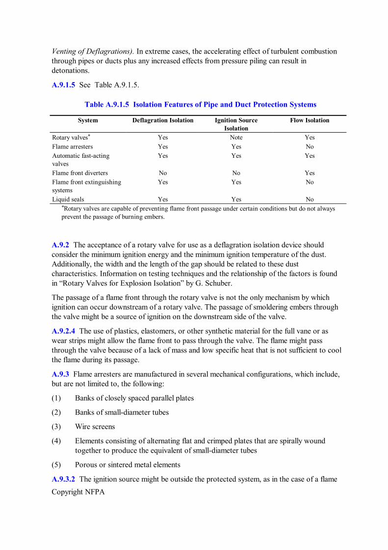
Copyright NFPA
Venting of Deflagrations). In extreme cases, the accelerating effect of turbulent combustion through pipes or ducts plus any increased effects from pressure piling can result in detonations.
A.9.1.5 See Table A.9.1.5.
Table A.9.1.5 Isolation Features of Pipe and Duct Protection Systems
System Deflagration Isolation Ignition Source Isolation
Flow Isolation
Rotary valves * Yes Note Yes Flame arresters Yes Yes No Automatic fastacting valves
Yes Yes Yes
Flame front diverters No No Yes Flame front extinguishing systems
Yes Yes No
Liquid seals Yes Yes No * Rotary valves are capable of preventing flame front passage under certain conditions but do not always prevent the passage of burning embers.
A.9.2 The acceptance of a rotary valve for use as a deflagration isolation device should consider the minimum ignition energy and the minimum ignition temperature of the dust. Additionally, the width and the length of the gap should be related to these dust characteristics. Information on testing techniques and the relationship of the factors is found in “Rotary Valves for Explosion Isolation” by G. Schuber.
The passage of a flame front through the rotary valve is not the only mechanism by which ignition can occur downstream of a rotary valve. The passage of smoldering embers through the valve might be a source of ignition on the downstream side of the valve.
A.9.2.4 The use of plastics, elastomers, or other synthetic material for the full vane or as wear strips might allow the flame front to pass through the valve. The flame might pass through the valve because of a lack of mass and low specific heat that is not sufficient to cool the flame during its passage.
A.9.3 Flame arresters are manufactured in several mechanical configurations, which include, but are not limited to, the following:
(1) Banks of closely spaced parallel plates
(2) Banks of smalldiameter tubes
(3) Wire screens
(4) Elements consisting of alternating flat and crimped plates that are spirally wound together to produce the equivalent of smalldiameter tubes
(5) Porous or sintered metal elements
A.9.3.2 The ignition source might be outside the protected system, as in the case of a flame
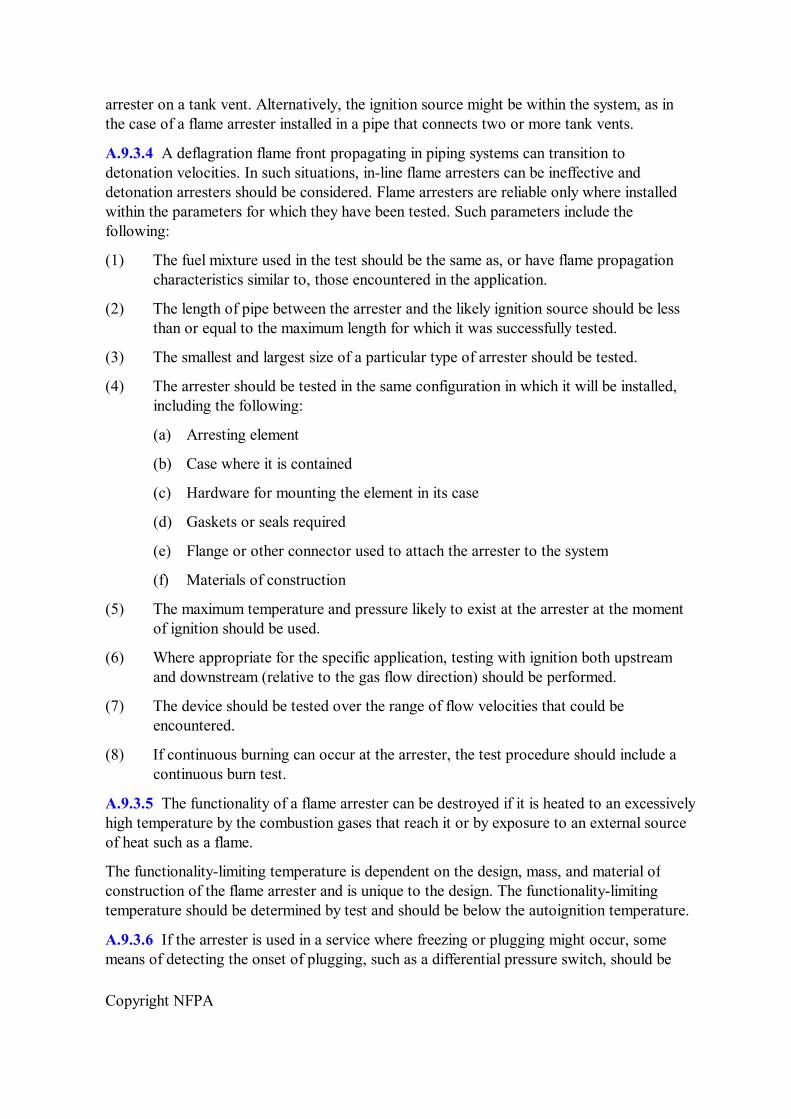
Copyright NFPA
arrester on a tank vent. Alternatively, the ignition source might be within the system, as in the case of a flame arrester installed in a pipe that connects two or more tank vents.
A.9.3.4 A deflagration flame front propagating in piping systems can transition to detonation velocities. In such situations, inline flame arresters can be ineffective and detonation arresters should be considered. Flame arresters are reliable only where installed within the parameters for which they have been tested. Such parameters include the following:
(1) The fuel mixture used in the test should be the same as, or have flame propagation characteristics similar to, those encountered in the application.
(2) The length of pipe between the arrester and the likely ignition source should be less than or equal to the maximum length for which it was successfully tested.
(3) The smallest and largest size of a particular type of arrester should be tested.
(4) The arrester should be tested in the same configuration in which it will be installed, including the following:
(a) Arresting element
(b) Case where it is contained
(c) Hardware for mounting the element in its case
(d) Gaskets or seals required
(e) Flange or other connector used to attach the arrester to the system
(f) Materials of construction
(5) The maximum temperature and pressure likely to exist at the arrester at the moment of ignition should be used.
(6) Where appropriate for the specific application, testing with ignition both upstream and downstream (relative to the gas flow direction) should be performed.
(7) The device should be tested over the range of flow velocities that could be encountered.
(8) If continuous burning can occur at the arrester, the test procedure should include a continuous burn test.
A.9.3.5 The functionality of a flame arrester can be destroyed if it is heated to an excessively high temperature by the combustion gases that reach it or by exposure to an external source of heat such as a flame.
The functionalitylimiting temperature is dependent on the design, mass, and material of construction of the flame arrester and is unique to the design. The functionalitylimiting temperature should be determined by test and should be below the autoignition temperature.
A.9.3.6 If the arrester is used in a service where freezing or plugging might occur, some means of detecting the onset of plugging, such as a differential pressure switch, should be
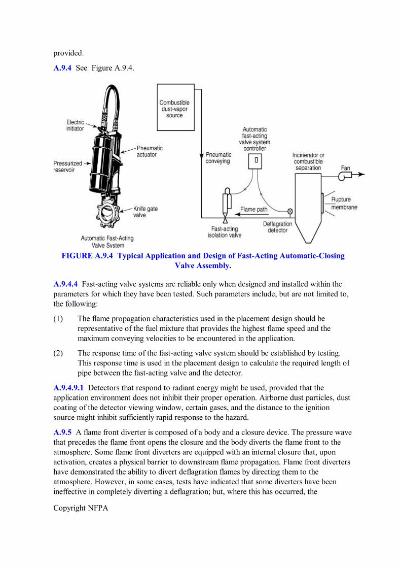
Copyright NFPA
provided.
A.9.4 See Figure A.9.4.
FIGURE A.9.4 Typical Application and Design of FastActing AutomaticClosing Valve Assembly.
A.9.4.4 Fastacting valve systems are reliable only when designed and installed within the parameters for which they have been tested. Such parameters include, but are not limited to, the following:
(1) The flame propagation characteristics used in the placement design should be representative of the fuel mixture that provides the highest flame speed and the maximum conveying velocities to be encountered in the application.
(2) The response time of the fastacting valve system should be established by testing. This response time is used in the placement design to calculate the required length of pipe between the fastacting valve and the detector.
A.9.4.9.1 Detectors that respond to radiant energy might be used, provided that the application environment does not inhibit their proper operation. Airborne dust particles, dust coating of the detector viewing window, certain gases, and the distance to the ignition source might inhibit sufficiently rapid response to the hazard.
A.9.5 A flame front diverter is composed of a body and a closure device. The pressure wave that precedes the flame front opens the closure and the body diverts the flame front to the atmosphere. Some flame front diverters are equipped with an internal closure that, upon activation, creates a physical barrier to downstream flame propagation. Flame front diverters have demonstrated the ability to divert deflagration flames by directing them to the atmosphere. However, in some cases, tests have indicated that some diverters have been ineffective in completely diverting a deflagration; but, where this has occurred, the
Copyright NFPA
deflagration severity in the system has been reduced. See Figure A.9.5.
FIGURE A.9.5 Typical Application and Design of Flame Front Diverters.
A.9.5.9 The testing of flame front diverters should include, but not be limited to, the following:
(1) The test fuel mixture should be the same as, or have flame propagation characteristics similar to, those encountered.
(2) The length of pipe between the installed flame front diverter and the ignition source should be less than or equal to the maximum length for which the diverter was tested.
(3) Ignition source location (upstream, downstream, or both locations) should be tested in the same configuration as the protection application.
(4) For upstream ignition, the diverter should be tested over the range of flow velocities that could be encountered at the time of ignition or that might develop as a result of ignition.
(5) Installation and maintenance should be as follows:
(a) Flame front diverters should be installed and maintained according to manufacturer's instructions.
(b) Flame front diverters should be inspected periodically, based on facility experience, and after each operation.
Copyright NFPA
(c) Inspection should determine whether any damage that could affect the performance of the device has occurred.
(d) Damaged components should be repaired or replaced.
A.9.7 For most systems, API Recommended Practice 521, Guide for PressureRelieving and Depressuring Systems, should be used when designing liquid seals. For systems where the oxidant/flammable gas might approach a stoichiometric mixture, tests should be performed to determine the design of liquid seals.
A.9.7.3 Where the inlet gas is a combustible mixture, additional precautions should be taken to prevent overheating of inlet piping within the liquid seal device by a continuous fire in the seal enclosure.
A.10.1.5 Pressure piling and flamejet ignition can significantly increase deflagration pressures in attached equipment. Techniques such as isolation or venting should be considered.
A.10.2.1 Deflagration pressure containment is not adequate for detonable systems because the maximum pressure rise is much greater than the factors established in 10.3.3.1 through 10.3.3.4. It should be recognized that some systems might be capable of deflagration or detonation. For example, systems containing a substantial proportion of hydrogen are prone to detonation, as are systems containing acetylene or acetylenic compounds. Saturated organic compounds such as propane, ethane, and alcohols generally do not detonate in vessels but might do so in pipework. Internals in equipment can promote the transition from deflagration to detonation.
A.10.2.2 When two vessels connected by a largediameter pipe both contain a combustible mixture, a deflagration in one vessel can precompress the unburned mixture in the other vessel. The maximum deflagration pressure that can be developed in the second vessel might be substantially greater than would normally happen in a single vessel. (See W. Bartknecht, Explosions: Course, Prevention, Protection, pp. 18–23.)
A.10.2.3 Only limited information is available for deflagration containment of systems with initial gauge pressures exceeding 2 bar (30 psi). Increased initial pressure might increase the potential for detonation. For this reason it is recommended that, for systems that might operate at an initial gauge pressure of 2 bar (30 psi) or higher, deflagration pressure containment should be used only where applicable test data are available. The testing should be carefully designed because the detonation potential of a system is affected by vessel dimensions.
A.10.3.3 For vessels fabricated of lowcarbon steel and lowalloy stainless steel, F u equals approximately 4.0 and F y equals approximately 2.0. The formulas are based on a paper by Noronha et al., “Deflagration Pressure Containment for Vessel Safety Containment for Vessel Safety Design, Plant/Operations Progress.”
A.10.3.3.1 The maximum deflagration pressures for several dusts can be found in Annex D of NFPA 68, Guide for Venting of Deflagrations.
A.10.3.5 The maximum initial pressure depends on the origin of the pressure. In some cases,
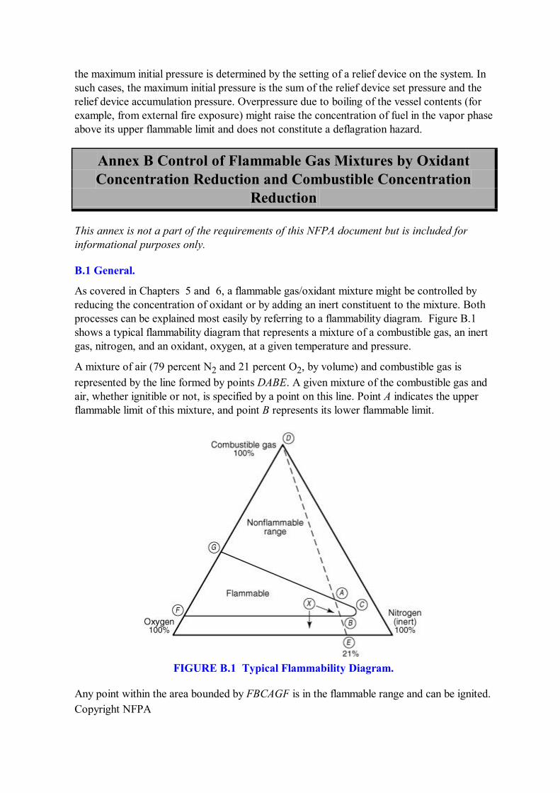
Copyright NFPA
the maximum initial pressure is determined by the setting of a relief device on the system. In such cases, the maximum initial pressure is the sum of the relief device set pressure and the relief device accumulation pressure. Overpressure due to boiling of the vessel contents (for example, from external fire exposure) might raise the concentration of fuel in the vapor phase above its upper flammable limit and does not constitute a deflagration hazard.
Annex B Control of Flammable Gas Mixtures by Oxidant Concentration Reduction and Combustible Concentration
Reduction
This annex is not a part of the requirements of this NFPA document but is included for informational purposes only.
B.1 General.
As covered in Chapters 5 and 6, a flammable gas/oxidant mixture might be controlled by reducing the concentration of oxidant or by adding an inert constituent to the mixture. Both processes can be explained most easily by referring to a flammability diagram. Figure B.1 shows a typical flammability diagram that represents a mixture of a combustible gas, an inert gas, nitrogen, and an oxidant, oxygen, at a given temperature and pressure.
A mixture of air (79 percent N 2 and 21 percent O 2 , by volume) and combustible gas is represented by the line formed by points DABE. A given mixture of the combustible gas and air, whether ignitible or not, is specified by a point on this line. Point A indicates the upper flammable limit of this mixture, and point B represents its lower flammable limit.
FIGURE B.1 Typical Flammability Diagram.
Any point within the area bounded by FBCAGF is in the flammable range and can be ignited.
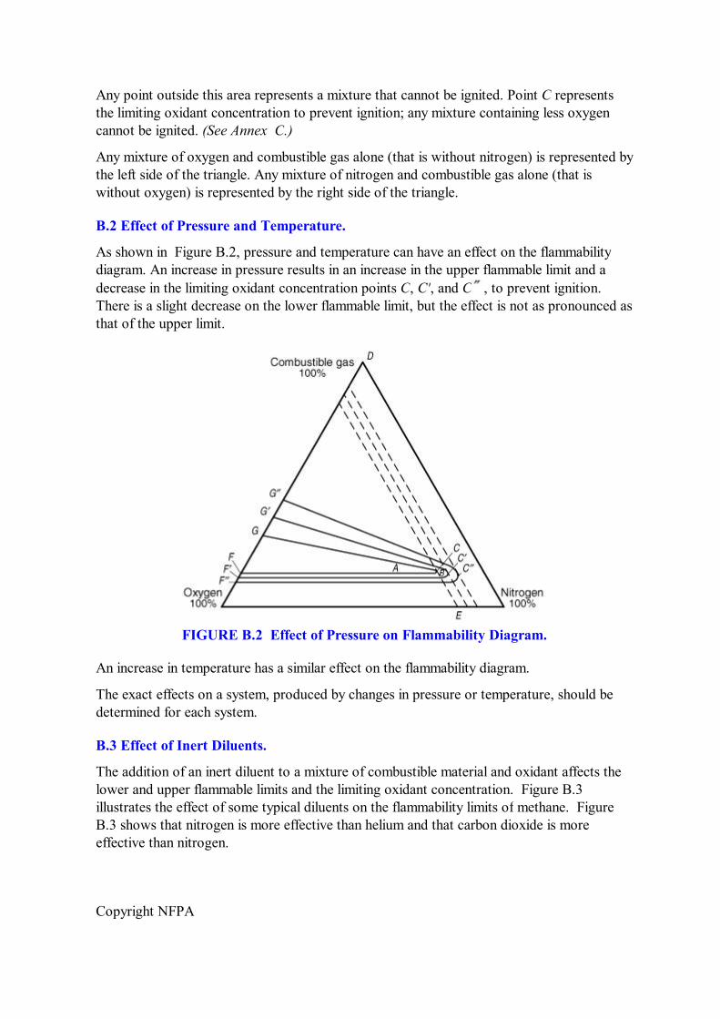
Copyright NFPA
Any point outside this area represents a mixture that cannot be ignited. Point C represents the limiting oxidant concentration to prevent ignition; any mixture containing less oxygen cannot be ignited. (See Annex C.)
Any mixture of oxygen and combustible gas alone (that is without nitrogen) is represented by the left side of the triangle. Any mixture of nitrogen and combustible gas alone (that is without oxygen) is represented by the right side of the triangle.
B.2 Effect of Pressure and Temperature.
As shown in Figure B.2, pressure and temperature can have an effect on the flammability diagram. An increase in pressure results in an increase in the upper flammable limit and a decrease in the limiting oxidant concentration points C, C', and C , to prevent ignition. There is a slight decrease on the lower flammable limit, but the effect is not as pronounced as that of the upper limit.
FIGURE B.2 Effect of Pressure on Flammability Diagram.
An increase in temperature has a similar effect on the flammability diagram.
The exact effects on a system, produced by changes in pressure or temperature, should be determined for each system.
B.3 Effect of Inert Diluents.
The addition of an inert diluent to a mixture of combustible material and oxidant affects the lower and upper flammable limits and the limiting oxidant concentration. Figure B.3 illustrates the effect of some typical diluents on the flammability limits of methane. Figure B.3 shows that nitrogen is more effective than helium and that carbon dioxide is more effective than nitrogen.
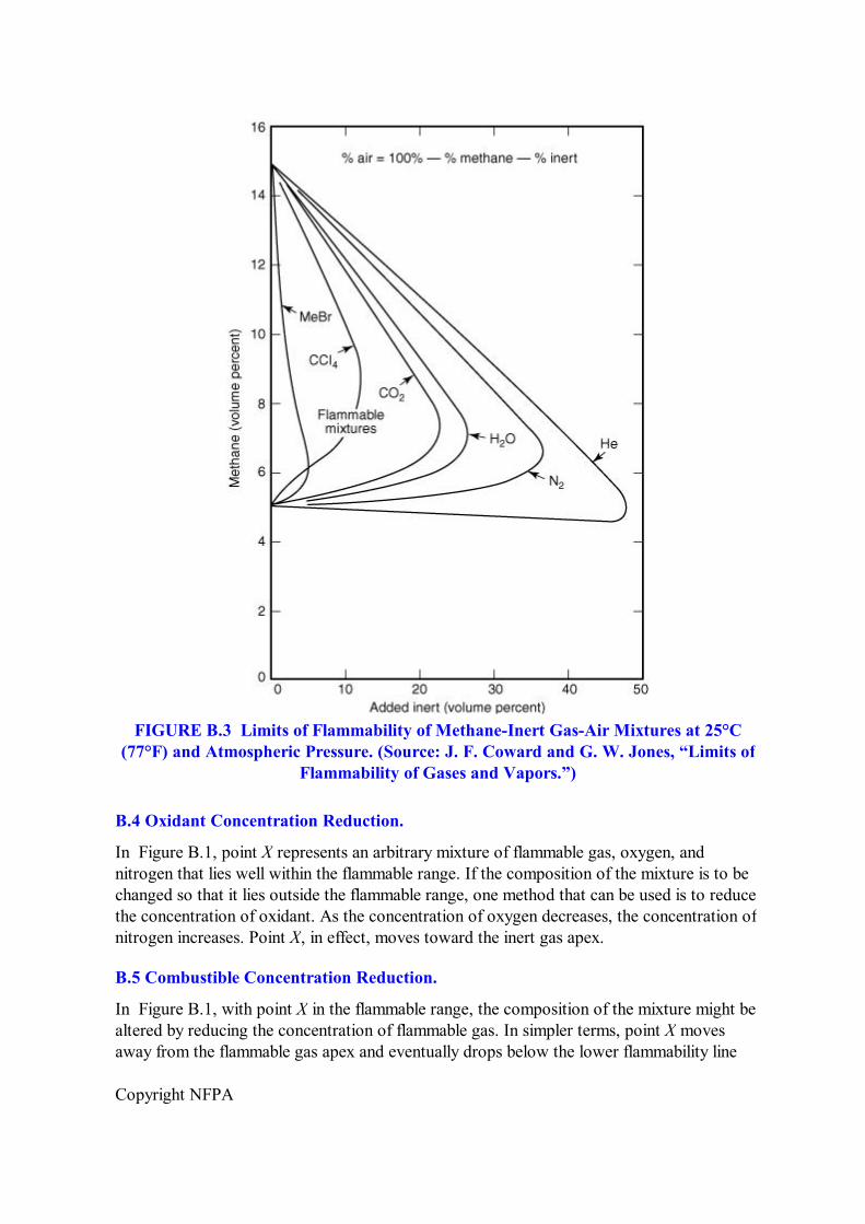
Copyright NFPA
FIGURE B.3 Limits of Flammability of MethaneInert GasAir Mixtures at 25°C (77°F) and Atmospheric Pressure. (Source: J. F. Coward and G. W. Jones, “Limits of
Flammability of Gases and Vapors.”)
B.4 Oxidant Concentration Reduction.
In Figure B.1, point X represents an arbitrary mixture of flammable gas, oxygen, and nitrogen that lies well within the flammable range. If the composition of the mixture is to be changed so that it lies outside the flammable range, one method that can be used is to reduce the concentration of oxidant. As the concentration of oxygen decreases, the concentration of nitrogen increases. Point X, in effect, moves toward the inert gas apex.
B.5 Combustible Concentration Reduction.
In Figure B.1, with point X in the flammable range, the composition of the mixture might be altered by reducing the concentration of flammable gas. In simpler terms, point X moves away from the flammable gas apex and eventually drops below the lower flammability line
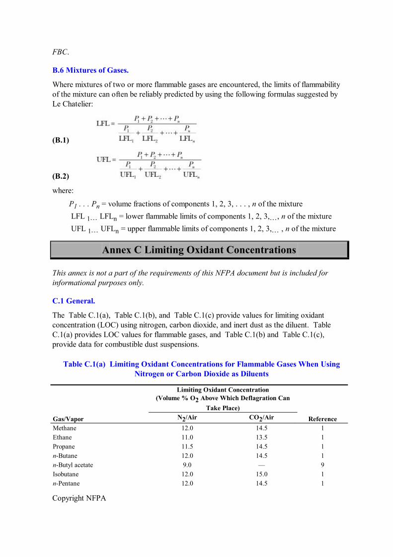
Copyright NFPA
FBC.
B.6 Mixtures of Gases.
Where mixtures of two or more flammable gases are encountered, the limits of flammability of the mixture can often be reliably predicted by using the following formulas suggested by Le Chatelier:
(B.1)
(B.2)
where:
P 1 . . . P n = volume fractions of components 1, 2, 3, . . . , n of the mixture LFL 1 LFL n = lower flammable limits of components 1, 2, 3, , n of the mixture UFL 1 UFL n = upper flammable limits of components 1, 2, 3, , n of the mixture
Annex C Limiting Oxidant Concentrations
This annex is not a part of the requirements of this NFPA document but is included for informational purposes only.
C.1 General.
The Table C.1(a), Table C.1(b), and Table C.1(c) provide values for limiting oxidant concentration (LOC) using nitrogen, carbon dioxide, and inert dust as the diluent. Table C.1(a) provides LOC values for flammable gases, and Table C.1(b) and Table C.1(c), provide data for combustible dust suspensions.
Table C.1(a) Limiting Oxidant Concentrations for Flammable Gases When Using Nitrogen or Carbon Dioxide as Diluents
Gas/Vapor
Limiting Oxidant Concentration (Volume % O 2 Above Which Deflagration Can
Take Place) Reference N 2 /Air CO 2 /Air
Methane 12.0 14.5 1 Ethane 11.0 13.5 1 Propane 11.5 14.5 1 nButane 12.0 14.5 1 nButyl acetate 9.0 — 9 Isobutane 12.0 15.0 1 nPentane 12.0 14.5 1
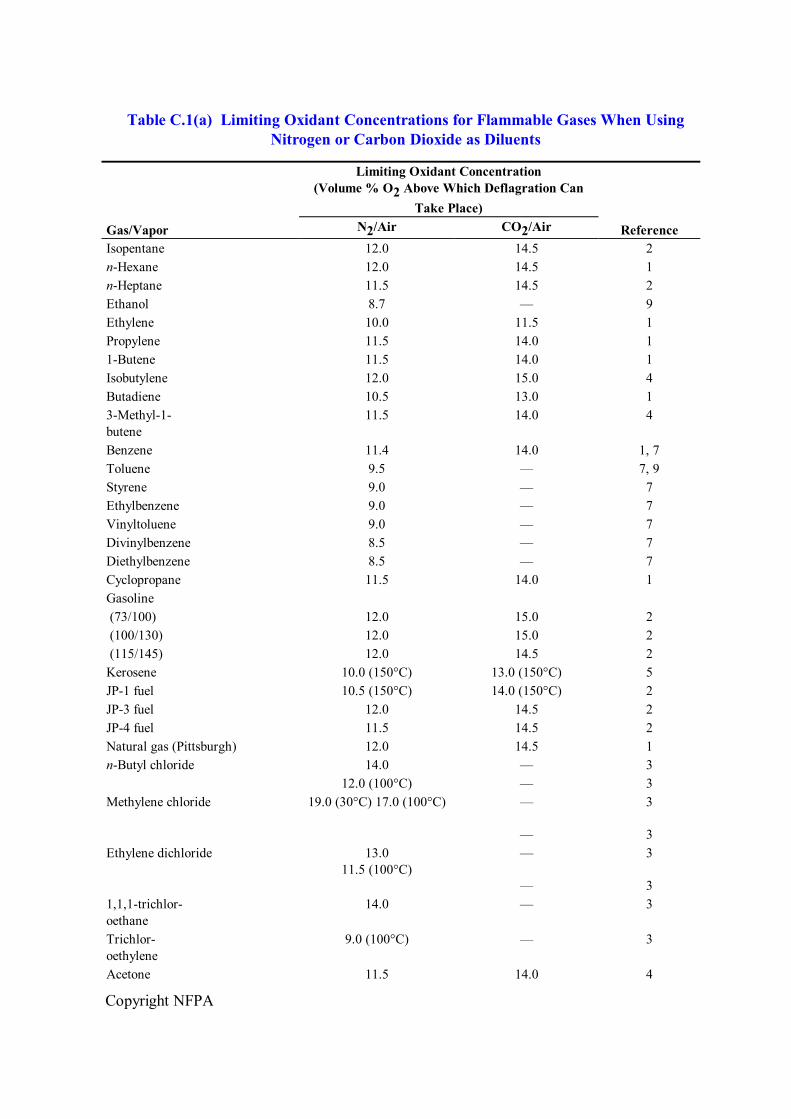
Copyright NFPA
Table C.1(a) Limiting Oxidant Concentrations for Flammable Gases When Using Nitrogen or Carbon Dioxide as Diluents
Gas/Vapor
Limiting Oxidant Concentration (Volume % O 2 Above Which Deflagration Can
Take Place) Reference N 2 /Air CO 2 /Air
Isopentane 12.0 14.5 2 nHexane 12.0 14.5 1 nHeptane 11.5 14.5 2 Ethanol 8.7 — 9 Ethylene 10.0 11.5 1 Propylene 11.5 14.0 1 1Butene 11.5 14.0 1 Isobutylene 12.0 15.0 4 Butadiene 10.5 13.0 1 3Methyl1 butene
11.5 14.0 4
Benzene 11.4 14.0 1, 7 Toluene 9.5 — 7, 9 Styrene 9.0 — 7 Ethylbenzene 9.0 — 7 Vinyltoluene 9.0 — 7 Divinylbenzene 8.5 — 7 Diethylbenzene 8.5 — 7 Cyclopropane 11.5 14.0 1 Gasoline (73/100) 12.0 15.0 2 (100/130) 12.0 15.0 2 (115/145) 12.0 14.5 2 Kerosene 10.0 (150°C) 13.0 (150°C) 5 JP1 fuel 10.5 (150°C) 14.0 (150°C) 2 JP3 fuel 12.0 14.5 2 JP4 fuel 11.5 14.5 2 Natural gas (Pittsburgh) 12.0 14.5 1 nButyl chloride 14.0 — 3
12.0 (100°C) — 3 Methylene chloride 19.0 (30°C) 17.0 (100°C) —
—
3
3 Ethylene dichloride 13.0
11.5 (100°C) —
—
3
3 1,1,1trichlor oethane
14.0 — 3
Trichlor oethylene
9.0 (100°C) — 3
Acetone 11.5 14.0 4
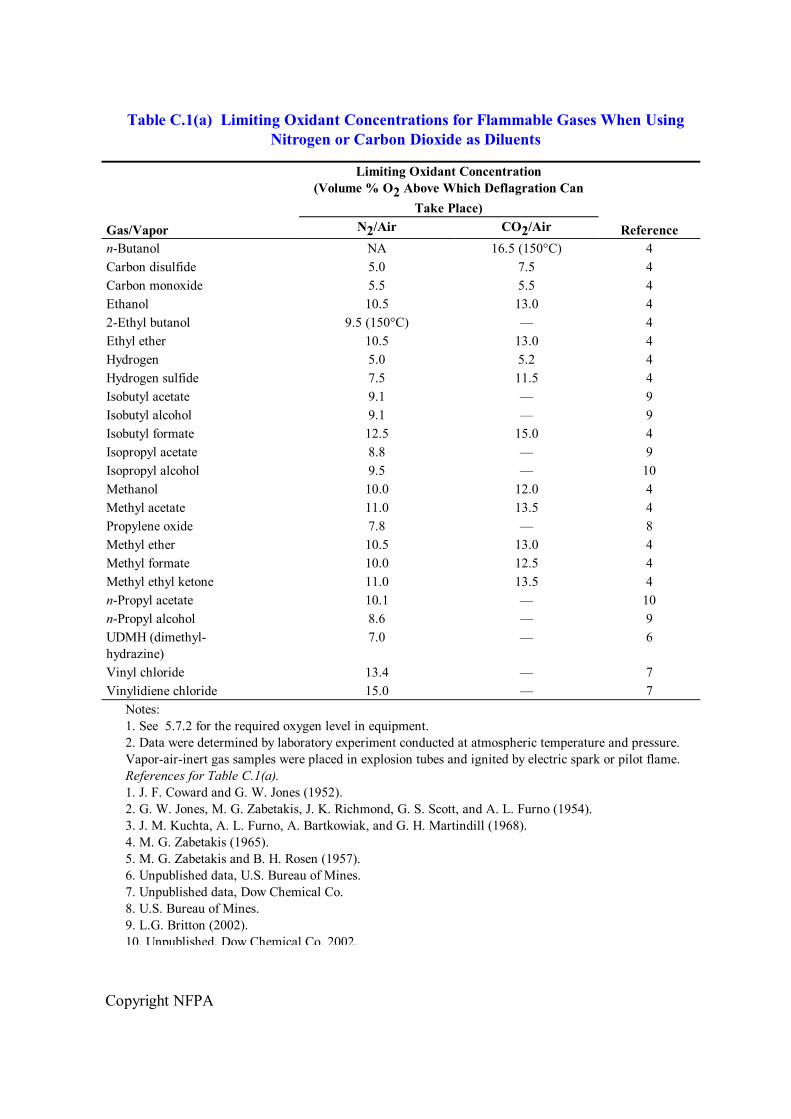
Copyright NFPA
Table C.1(a) Limiting Oxidant Concentrations for Flammable Gases When Using Nitrogen or Carbon Dioxide as Diluents
Gas/Vapor
Limiting Oxidant Concentration (Volume % O 2 Above Which Deflagration Can
Take Place) Reference N 2 /Air CO 2 /Air
nButanol NA 16.5 (150°C) 4 Carbon disulfide 5.0 7.5 4 Carbon monoxide 5.5 5.5 4 Ethanol 10.5 13.0 4 2Ethyl butanol 9.5 (150°C) — 4 Ethyl ether 10.5 13.0 4 Hydrogen 5.0 5.2 4 Hydrogen sulfide 7.5 11.5 4 Isobutyl acetate 9.1 — 9 Isobutyl alcohol 9.1 — 9 Isobutyl formate 12.5 15.0 4 Isopropyl acetate 8.8 — 9 Isopropyl alcohol 9.5 — 10 Methanol 10.0 12.0 4 Methyl acetate 11.0 13.5 4 Propylene oxide 7.8 — 8 Methyl ether 10.5 13.0 4 Methyl formate 10.0 12.5 4 Methyl ethyl ketone 11.0 13.5 4 nPropyl acetate 10.1 — 10 nPropyl alcohol 8.6 — 9 UDMH (dimethyl hydrazine)
7.0 — 6
Vinyl chloride 13.4 — 7 Vinylidiene chloride 15.0 — 7
Notes: 1. See 5.7.2 for the required oxygen level in equipment. 2. Data were determined by laboratory experiment conducted at atmospheric temperature and pressure. Vaporairinert gas samples were placed in explosion tubes and ignited by electric spark or pilot flame. References for Table C.1(a). 1. J. F. Coward and G. W. Jones (1952). 2. G. W. Jones, M. G. Zabetakis, J. K. Richmond, G. S. Scott, and A. L. Furno (1954). 3. J. M. Kuchta, A. L. Furno, A. Bartkowiak, and G. H. Martindill (1968). 4. M. G. Zabetakis (1965). 5. M. G. Zabetakis and B. H. Rosen (1957). 6. Unpublished data, U.S. Bureau of Mines. 7. Unpublished data, Dow Chemical Co. 8. U.S. Bureau of Mines. 9. L.G. Britton (2002). 10. Unpublished, Dow Chemical Co. 2002.
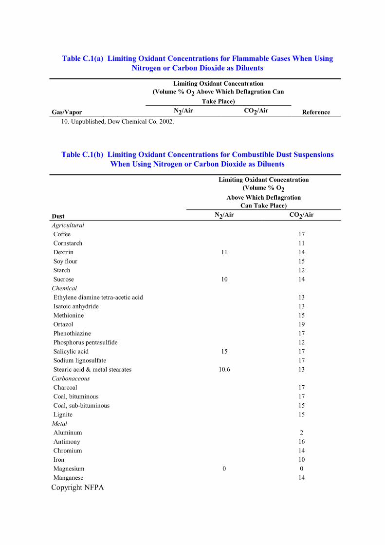
Copyright NFPA
Table C.1(a) Limiting Oxidant Concentrations for Flammable Gases When Using Nitrogen or Carbon Dioxide as Diluents
Gas/Vapor
Limiting Oxidant Concentration (Volume % O 2 Above Which Deflagration Can
Take Place) Reference N 2 /Air CO 2 /Air 9. L.G. Britton (2002).
10. Unpublished, Dow Chemical Co. 2002.
Table C.1(b) Limiting Oxidant Concentrations for Combustible Dust Suspensions When Using Nitrogen or Carbon Dioxide as Diluents
Dust
Limiting Oxidant Concentration (Volume % O 2
Above Which Deflagration Can Take Place)
N 2 /Air CO 2 /Air Agricultural Coffee 17 Cornstarch 11 Dextrin 11 14 Soy flour 15 Starch 12 Sucrose 10 14 Chemical Ethylene diamine tetraacetic acid 13 Isatoic anhydride 13 Methionine 15 Ortazol 19 Phenothiazine 17 Phosphorus pentasulfide 12 Salicylic acid 15 17 Sodium lignosulfate 17 Stearic acid & metal stearates 10.6 13 Carbonaceous Charcoal 17 Coal, bituminous 17 Coal, subbituminous 15 Lignite 15 Metal Aluminum 2 Antimony 16 Chromium 14 Iron 10 Magnesium 0 0 Manganese 14
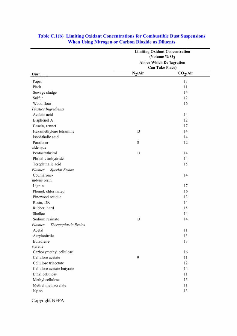
Copyright NFPA
Table C.1(b) Limiting Oxidant Concentrations for Combustible Dust Suspensions When Using Nitrogen or Carbon Dioxide as Diluents
Dust
Limiting Oxidant Concentration (Volume % O 2
Above Which Deflagration Can Take Place)
N 2 /Air CO 2 /Air Cellulose 13 Paper 13 Pitch 11 Sewage sludge 14 Sulfur 12 Wood flour 16 Plastics Ingredients Azelaic acid 14 Bisphenol A 12 Casein, rennet 17 Hexamethylene tetramine 13 14 Isophthalic acid 14 Paraform aldehyde
8 12
Pentaerythritol 13 14 Phthalic anhydride 14 Terephthalic acid 15 Plastics — Special Resins Coumarone indene resin
14
Lignin 17 Phenol, chlorinated 16 Pinewood residue 13 Rosin, DK 14 Rubber, hard 15 Shellac 14 Sodium resinate 13 14 Plastics — Thermoplastic Resins Acetal 11 Acrylonitrile 13 Butadiene styrene
13
Carboxymethyl cellulose 16 Cellulose acetate 9 11 Cellulose triacetate 12 Cellulose acetate butyrate 14 Ethyl cellulose 11 Methyl cellulose 13 Methyl methacrylate 11 Nylon 13
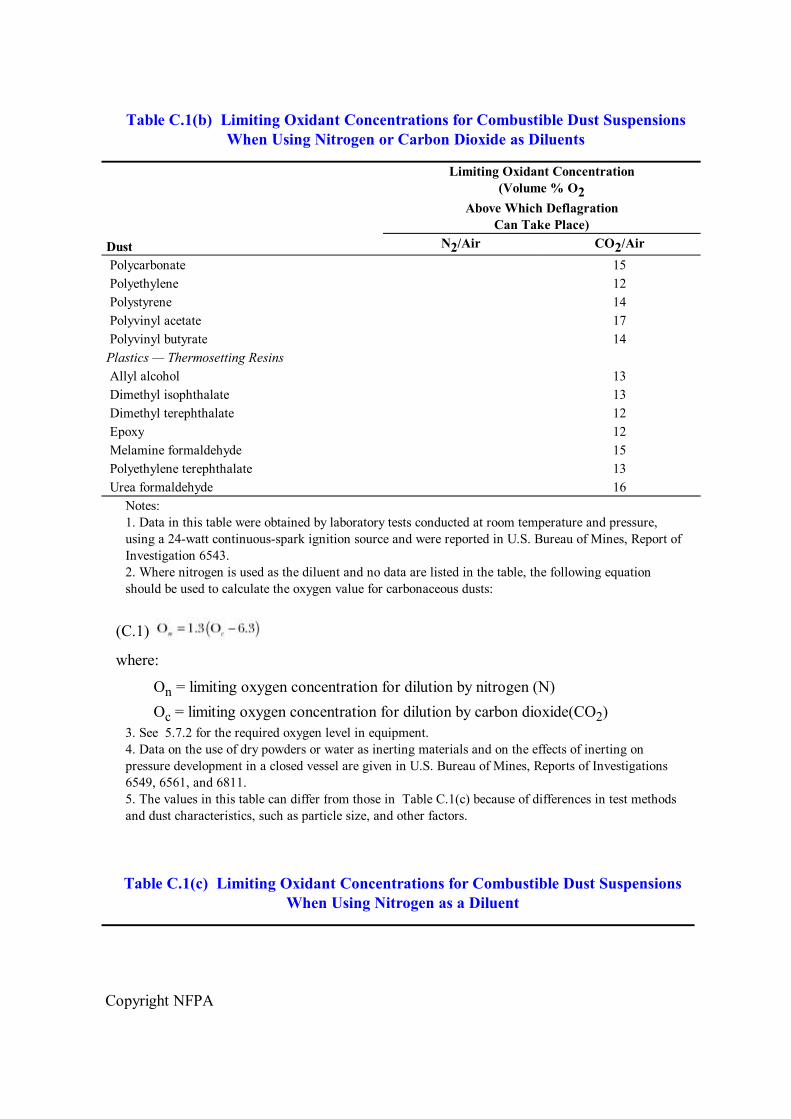
Copyright NFPA
Table C.1(b) Limiting Oxidant Concentrations for Combustible Dust Suspensions When Using Nitrogen or Carbon Dioxide as Diluents
Dust
Limiting Oxidant Concentration (Volume % O 2
Above Which Deflagration Can Take Place)
N 2 /Air CO 2 /Air Polycarbonate 15 Polyethylene 12 Polystyrene 14 Polyvinyl acetate 17 Polyvinyl butyrate 14 Plastics — Thermosetting Resins Allyl alcohol 13 Dimethyl isophthalate 13 Dimethyl terephthalate 12 Epoxy 12 Melamine formaldehyde 15 Polyethylene terephthalate 13 Urea formaldehyde 16
Notes: 1. Data in this table were obtained by laboratory tests conducted at room temperature and pressure, using a 24watt continuousspark ignition source and were reported in U.S. Bureau of Mines, Report of Investigation 6543. 2. Where nitrogen is used as the diluent and no data are listed in the table, the following equation should be used to calculate the oxygen value for carbonaceous dusts:
(C.1)
where:
O n = limiting oxygen concentration for dilution by nitrogen (N) O c = limiting oxygen concentration for dilution by carbon dioxide(CO 2 )
3. See 5.7.2 for the required oxygen level in equipment. 4. Data on the use of dry powders or water as inerting materials and on the effects of inerting on pressure development in a closed vessel are given in U.S. Bureau of Mines, Reports of Investigations 6549, 6561, and 6811. 5. The values in this table can differ from those in Table C.1(c) because of differences in test methods and dust characteristics, such as particle size, and other factors.
Table C.1(c) Limiting Oxidant Concentrations for Combustible Dust Suspensions When Using Nitrogen as a Diluent
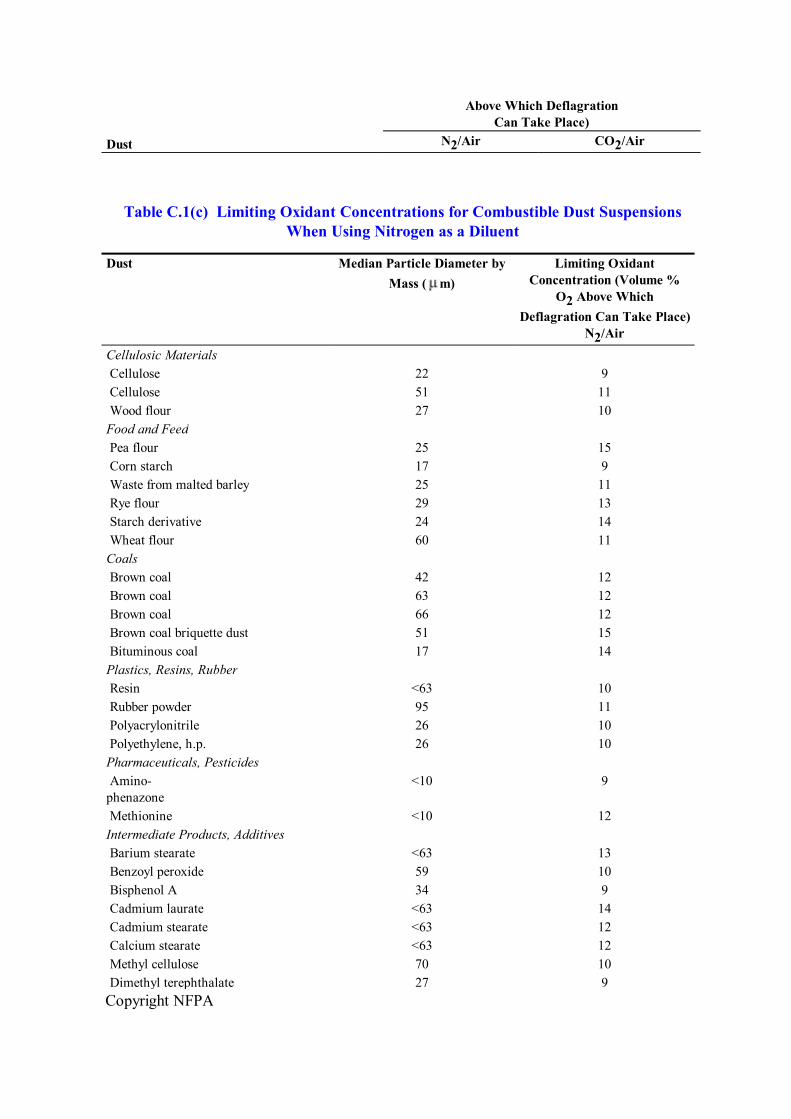
Copyright NFPA
Dust
(Volume % O 2 Above Which Deflagration
Can Take Place) N 2 /Air CO 2 /Air
Table C.1(c) Limiting Oxidant Concentrations for Combustible Dust Suspensions When Using Nitrogen as a Diluent
Dust Median Particle Diameter by Mass ( m)
Limiting Oxidant Concentration (Volume %
O 2 Above Which Deflagration Can Take Place)
N 2 /Air Cellulosic Materials Cellulose 22 9 Cellulose 51 11 Wood flour 27 10 Food and Feed Pea flour 25 15 Corn starch 17 9 Waste from malted barley 25 11 Rye flour 29 13 Starch derivative 24 14 Wheat flour 60 11 Coals Brown coal 42 12 Brown coal 63 12 Brown coal 66 12 Brown coal briquette dust 51 15 Bituminous coal 17 14 Plastics, Resins, Rubber Resin <63 10 Rubber powder 95 11 Polyacrylonitrile 26 10 Polyethylene, h.p. 26 10 Pharmaceuticals, Pesticides Amino phenazone
<10 9
Methionine <10 12 Intermediate Products, Additives Barium stearate <63 13 Benzoyl peroxide 59 10 Bisphenol A 34 9 Cadmium laurate <63 14 Cadmium stearate <63 12 Calcium stearate <63 12 Methyl cellulose 70 10 Dimethyl terephthalate 27 9
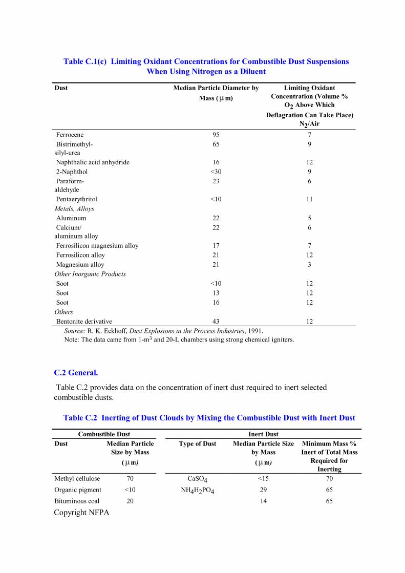
Copyright NFPA
Table C.1(c) Limiting Oxidant Concentrations for Combustible Dust Suspensions When Using Nitrogen as a Diluent
Dust Median Particle Diameter by Mass ( m)
Limiting Oxidant Concentration (Volume %
O 2 Above Which Deflagration Can Take Place)
N 2 /Air Ferrocene 95 7 Bistrimethyl silylurea
65 9
Naphthalic acid anhydride 16 12 2Naphthol <30 9 Paraform aldehyde
23 6
Pentaerythritol <10 11 Metals, Alloys Aluminum 22 5 Calcium/ aluminum alloy
22 6
Ferrosilicon magnesium alloy 17 7 Ferrosilicon alloy 21 12 Magnesium alloy 21 3 Other Inorganic Products Soot <10 12 Soot 13 12 Soot 16 12 Others Bentonite derivative 43 12 Source: R. K. Eckhoff, Dust Explosions in the Process Industries, 1991. Note: The data came from 1m 3 and 20L chambers using strong chemical igniters.
C.2 General.
Table C.2 provides data on the concentration of inert dust required to inert selected combustible dusts.
Table C.2 Inerting of Dust Clouds by Mixing the Combustible Dust with Inert Dust
Combustible Dust Inert Dust Dust Median Particle
Size by Mass ( m)
Type of Dust Median Particle Size by Mass ( m)
Minimum Mass % Inert of Total Mass
Required for Inerting
Methyl cellulose 70 CaSO 4 <15 70
Organic pigment <10 NH 4 H 2 PO 4 29 65
Bituminous coal 20 14 65
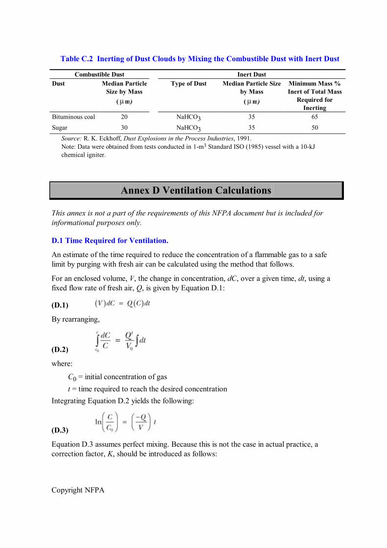
Copyright NFPA
Table C.2 Inerting of Dust Clouds by Mixing the Combustible Dust with Inert Dust
Combustible Dust Inert Dust Dust Median Particle
Size by Mass ( m)
Type of Dust Median Particle Size by Mass ( m)
Minimum Mass % Inert of Total Mass
Required for Inerting
Bituminous coal 20 NaHCO 3 35 65
Sugar 30 NaHCO 3 35 50 Source: R. K. Eckhoff, Dust Explosions in the Process Industries, 1991. Note: Data were obtained from tests conducted in 1m 3 Standard ISO (1985) vessel with a 10kJ chemical igniter.
Annex D Ventilation Calculations
This annex is not a part of the requirements of this NFPA document but is included for informational purposes only.
D.1 Time Required for Ventilation.
An estimate of the time required to reduce the concentration of a flammable gas to a safe limit by purging with fresh air can be calculated using the method that follows.
For an enclosed volume, V, the change in concentration, dC, over a given time, dt, using a fixed flow rate of fresh air, Q, is given by Equation D.1:
(D.1)
By rearranging,
(D.2)
where:
C 0 = initial concentration of gas t = time required to reach the desired concentration
Integrating Equation D.2 yields the following:
(D.3)
Equation D.3 assumes perfect mixing. Because this is not the case in actual practice, a correction factor, K, should be introduced as follows:
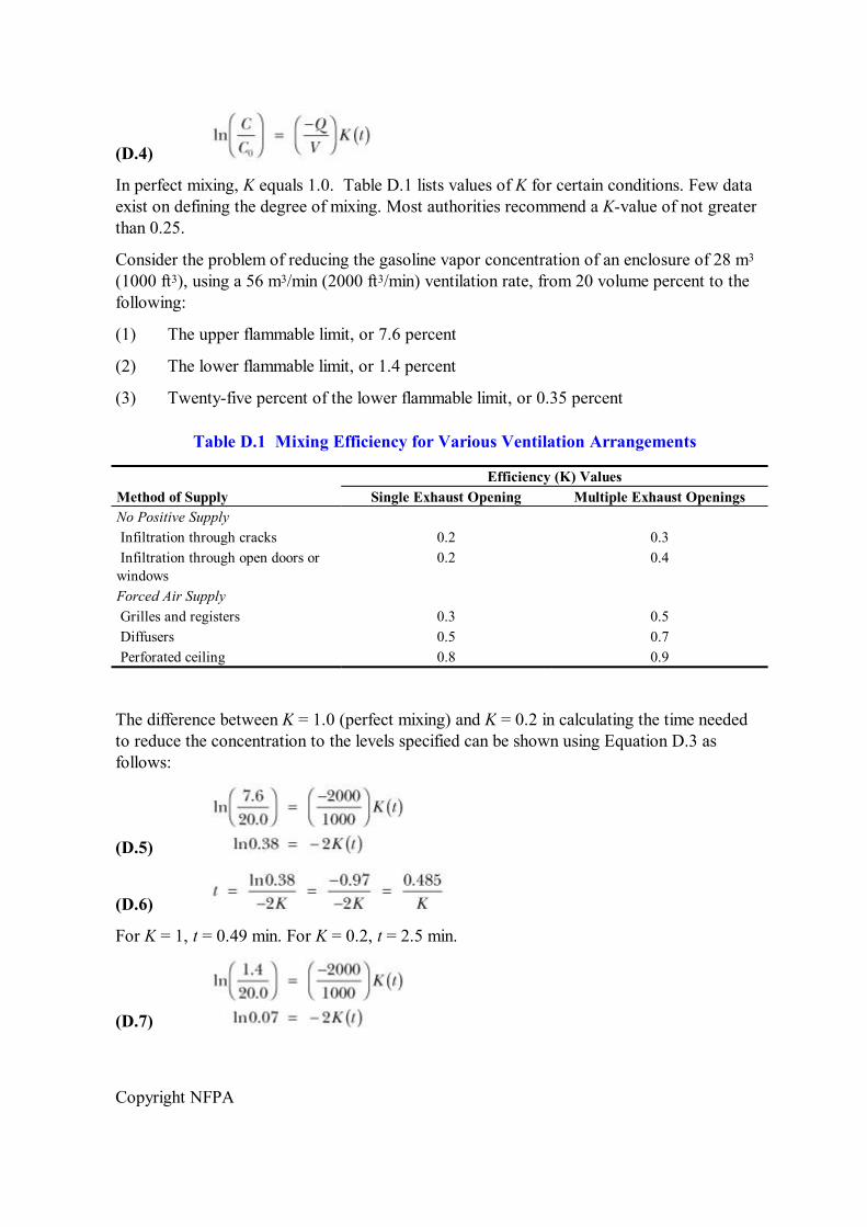
Copyright NFPA
(D.4)
In perfect mixing, K equals 1.0. Table D.1 lists values of K for certain conditions. Few data exist on defining the degree of mixing. Most authorities recommend a Kvalue of not greater than 0.25.
Consider the problem of reducing the gasoline vapor concentration of an enclosure of 28 m 3 (1000 ft 3 ), using a 56 m 3 /min (2000 ft 3 /min) ventilation rate, from 20 volume percent to the following:
(1) The upper flammable limit, or 7.6 percent
(2) The lower flammable limit, or 1.4 percent
(3) Twentyfive percent of the lower flammable limit, or 0.35 percent
Table D.1 Mixing Efficiency for Various Ventilation Arrangements
Efficiency (K) Values Method of Supply Single Exhaust Opening Multiple Exhaust Openings No Positive Supply Infiltration through cracks 0.2 0.3 Infiltration through open doors or windows
0.2 0.4
Forced Air Supply Grilles and registers 0.3 0.5 Diffusers 0.5 0.7 Perforated ceiling 0.8 0.9
The difference between K = 1.0 (perfect mixing) and K = 0.2 in calculating the time needed to reduce the concentration to the levels specified can be shown using Equation D.3 as follows:
(D.5)
(D.6)
For K = 1, t = 0.49 min. For K = 0.2, t = 2.5 min.
(D.7)
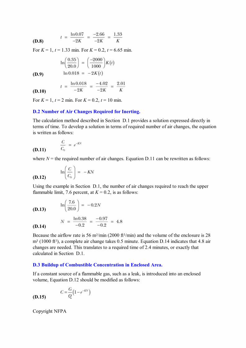
Copyright NFPA
(D.8)
For K = 1, t = 1.33 min. For K = 0.2, t = 6.65 min.
(D.9)
(D.10)
For K = 1, t = 2 min. For K = 0.2, t = 10 min.
D.2 Number of Air Changes Required for Inerting.
The calculation method described in Section D.1 provides a solution expressed directly in terms of time. To develop a solution in terms of required number of air changes, the equation is written as follows:
(D.11)
where N = the required number of air changes. Equation D.11 can be rewritten as follows:
(D.12)
Using the example in Section D.1, the number of air changes required to reach the upper flammable limit, 7.6 percent, at K = 0.2, is as follows:
(D.13)
(D.14)
Because the airflow rate is 56 m 3 /min (2000 ft 3 /min) and the volume of the enclosure is 28 m 3 (1000 ft 3 ), a complete air change takes 0.5 minute. Equation D.14 indicates that 4.8 air changes are needed. This translates to a required time of 2.4 minutes, or exactly that calculated in Section D.1.
D.3 Buildup of Combustible Concentration in Enclosed Area.
If a constant source of a flammable gas, such as a leak, is introduced into an enclosed volume, Equation D.12 should be modified as follows:
(D.15)
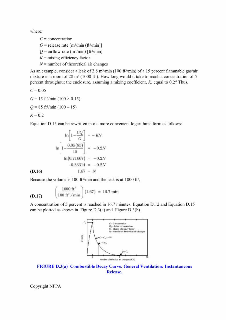
Copyright NFPA
where:
C = concentration G = release rate [m 3 /min (ft 3 /min)] Q = airflow rate (m 3 /min) [ft 3 /min] K = mixing efficiency factor N = number of theoretical air changes
As an example, consider a leak of 2.8 m 3 /min (100 ft 3 /min) of a 15 percent flammable gas/air mixture in a room of 28 m 3 (1000 ft 3 ). How long would it take to reach a concentration of 5 percent throughout the enclosure, assuming a mixing coefficient, K, equal to 0.2? Thus,
C = 0.05
G = 15 ft 3 /min (100 × 0.15)
Q = 85 ft 3 /min (100 – 15)
K = 0.2
Equation D.15 can be rewritten into a more convenient logarithmic form as follows:
(D.16)
Because the volume is 100 ft 3 /min and the leak is at 1000 ft 3 ,
(D.17)
A concentration of 5 percent is reached in 16.7 minutes. Equation D.12 and Equation D.15 can be plotted as shown in Figure D.3(a) and Figure D.3(b).
FIGURE D.3(a) Combustible Decay Curve. General Ventilation: Instantaneous Release.
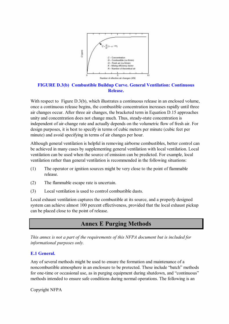
Copyright NFPA
FIGURE D.3(b) Combustible Buildup Curve. General Ventilation: Continuous Release.
With respect to Figure D.3(b), which illustrates a continuous release in an enclosed volume, once a continuous release begins, the combustible concentration increases rapidly until three air changes occur. After three air changes, the bracketed term in Equation D.15 approaches unity and concentration does not change much. Thus, steadystate concentration is independent of airchange rate and actually depends on the volumetric flow of fresh air. For design purposes, it is best to specify in terms of cubic meters per minute (cubic feet per minute) and avoid specifying in terms of air changes per hour.
Although general ventilation is helpful in removing airborne combustibles, better control can be achieved in many cases by supplementing general ventilation with local ventilation. Local ventilation can be used when the source of emission can be predicted. For example, local ventilation rather than general ventilation is recommended in the following situations:
(1) The operator or ignition sources might be very close to the point of flammable release.
(2) The flammable escape rate is uncertain.
(3) Local ventilation is used to control combustible dusts.
Local exhaust ventilation captures the combustible at its source, and a properly designed system can achieve almost 100 percent effectiveness, provided that the local exhaust pickup can be placed close to the point of release.
Annex E Purging Methods
This annex is not a part of the requirements of this NFPA document but is included for informational purposes only.
E.1 General.
Any of several methods might be used to ensure the formation and maintenance of a noncombustible atmosphere in an enclosure to be protected. These include “batch” methods for onetime or occasional use, as in purging equipment during shutdown, and “continuous” methods intended to ensure safe conditions during normal operations. The following is an
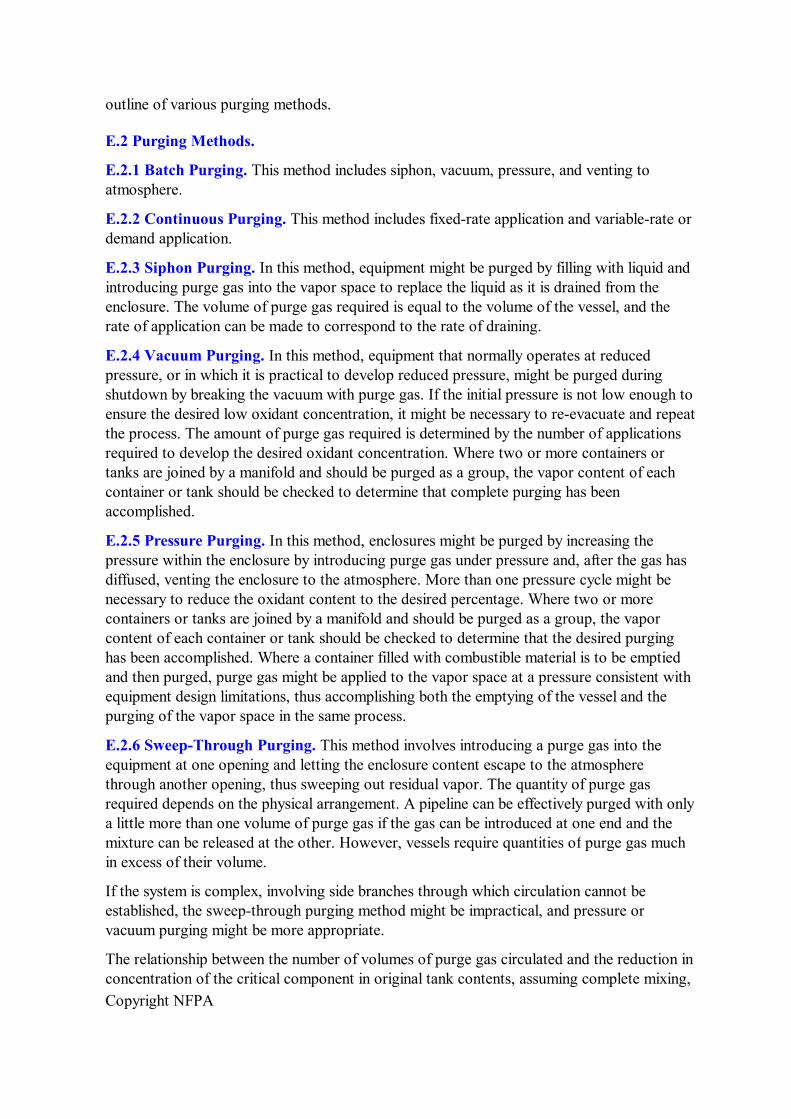
Copyright NFPA
outline of various purging methods.
E.2 Purging Methods.
E.2.1 Batch Purging. This method includes siphon, vacuum, pressure, and venting to atmosphere.
E.2.2 Continuous Purging. This method includes fixedrate application and variablerate or demand application.
E.2.3 Siphon Purging. In this method, equipment might be purged by filling with liquid and introducing purge gas into the vapor space to replace the liquid as it is drained from the enclosure. The volume of purge gas required is equal to the volume of the vessel, and the rate of application can be made to correspond to the rate of draining.
E.2.4 Vacuum Purging. In this method, equipment that normally operates at reduced pressure, or in which it is practical to develop reduced pressure, might be purged during shutdown by breaking the vacuum with purge gas. If the initial pressure is not low enough to ensure the desired low oxidant concentration, it might be necessary to reevacuate and repeat the process. The amount of purge gas required is determined by the number of applications required to develop the desired oxidant concentration. Where two or more containers or tanks are joined by a manifold and should be purged as a group, the vapor content of each container or tank should be checked to determine that complete purging has been accomplished.
E.2.5 Pressure Purging. In this method, enclosures might be purged by increasing the pressure within the enclosure by introducing purge gas under pressure and, after the gas has diffused, venting the enclosure to the atmosphere. More than one pressure cycle might be necessary to reduce the oxidant content to the desired percentage. Where two or more containers or tanks are joined by a manifold and should be purged as a group, the vapor content of each container or tank should be checked to determine that the desired purging has been accomplished. Where a container filled with combustible material is to be emptied and then purged, purge gas might be applied to the vapor space at a pressure consistent with equipment design limitations, thus accomplishing both the emptying of the vessel and the purging of the vapor space in the same process.
E.2.6 SweepThrough Purging. This method involves introducing a purge gas into the equipment at one opening and letting the enclosure content escape to the atmosphere through another opening, thus sweeping out residual vapor. The quantity of purge gas required depends on the physical arrangement. A pipeline can be effectively purged with only a little more than one volume of purge gas if the gas can be introduced at one end and the mixture can be released at the other. However, vessels require quantities of purge gas much in excess of their volume.
If the system is complex, involving side branches through which circulation cannot be established, the sweepthrough purging method might be impractical, and pressure or vacuum purging might be more appropriate.
The relationship between the number of volumes of purge gas circulated and the reduction in concentration of the critical component in original tank contents, assuming complete mixing,
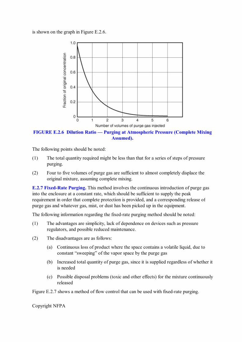
Copyright NFPA
is shown on the graph in Figure E.2.6.
FIGURE E.2.6 Dilution Ratio — Purging at Atmospheric Pressure (Complete Mixing Assumed).
The following points should be noted:
(1) The total quantity required might be less than that for a series of steps of pressure purging.
(2) Four to five volumes of purge gas are sufficient to almost completely displace the original mixture, assuming complete mixing.
E.2.7 FixedRate Purging. This method involves the continuous introduction of purge gas into the enclosure at a constant rate, which should be sufficient to supply the peak requirement in order that complete protection is provided, and a corresponding release of purge gas and whatever gas, mist, or dust has been picked up in the equipment.
The following information regarding the fixedrate purging method should be noted:
(1) The advantages are simplicity, lack of dependence on devices such as pressure regulators, and possible reduced maintenance.
(2) The disadvantages are as follows:
(a) Continuous loss of product where the space contains a volatile liquid, due to constant “sweeping” of the vapor space by the purge gas
(b) Increased total quantity of purge gas, since it is supplied regardless of whether it is needed
(c) Possible disposal problems (toxic and other effects) for the mixture continuously released
Figure E.2.7 shows a method of flow control that can be used with fixedrate purging.
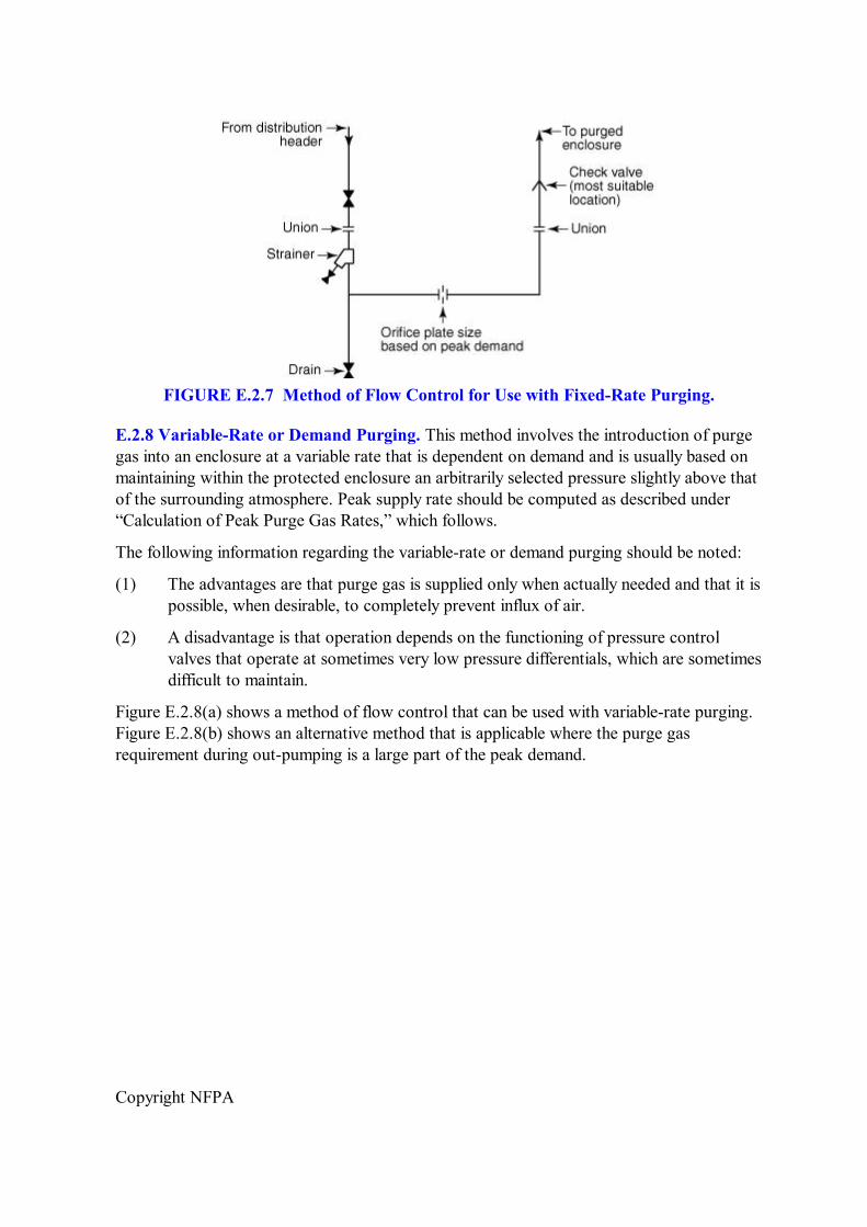
Copyright NFPA
FIGURE E.2.7 Method of Flow Control for Use with FixedRate Purging.
E.2.8 VariableRate or Demand Purging. This method involves the introduction of purge gas into an enclosure at a variable rate that is dependent on demand and is usually based on maintaining within the protected enclosure an arbitrarily selected pressure slightly above that of the surrounding atmosphere. Peak supply rate should be computed as described under “Calculation of Peak Purge Gas Rates,” which follows.
The following information regarding the variablerate or demand purging should be noted:
(1) The advantages are that purge gas is supplied only when actually needed and that it is possible, when desirable, to completely prevent influx of air.
(2) A disadvantage is that operation depends on the functioning of pressure control valves that operate at sometimes very low pressure differentials, which are sometimes difficult to maintain.
Figure E.2.8(a) shows a method of flow control that can be used with variablerate purging. Figure E.2.8(b) shows an alternative method that is applicable where the purge gas requirement during outpumping is a large part of the peak demand.
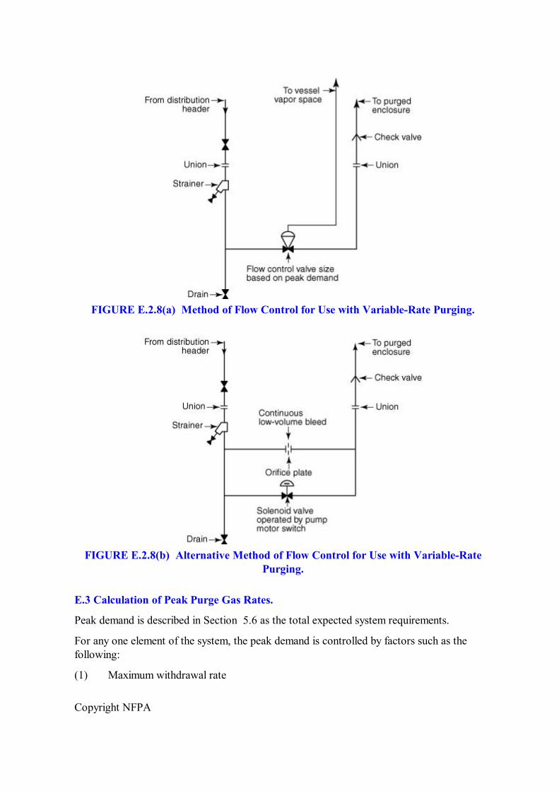
Copyright NFPA
FIGURE E.2.8(a) Method of Flow Control for Use with VariableRate Purging.
FIGURE E.2.8(b) Alternative Method of Flow Control for Use with VariableRate Purging.
E.3 Calculation of Peak Purge Gas Rates.
Peak demand is described in Section 5.6 as the total expected system requirements.
For any one element of the system, the peak demand is controlled by factors such as the following:
(1) Maximum withdrawal rate
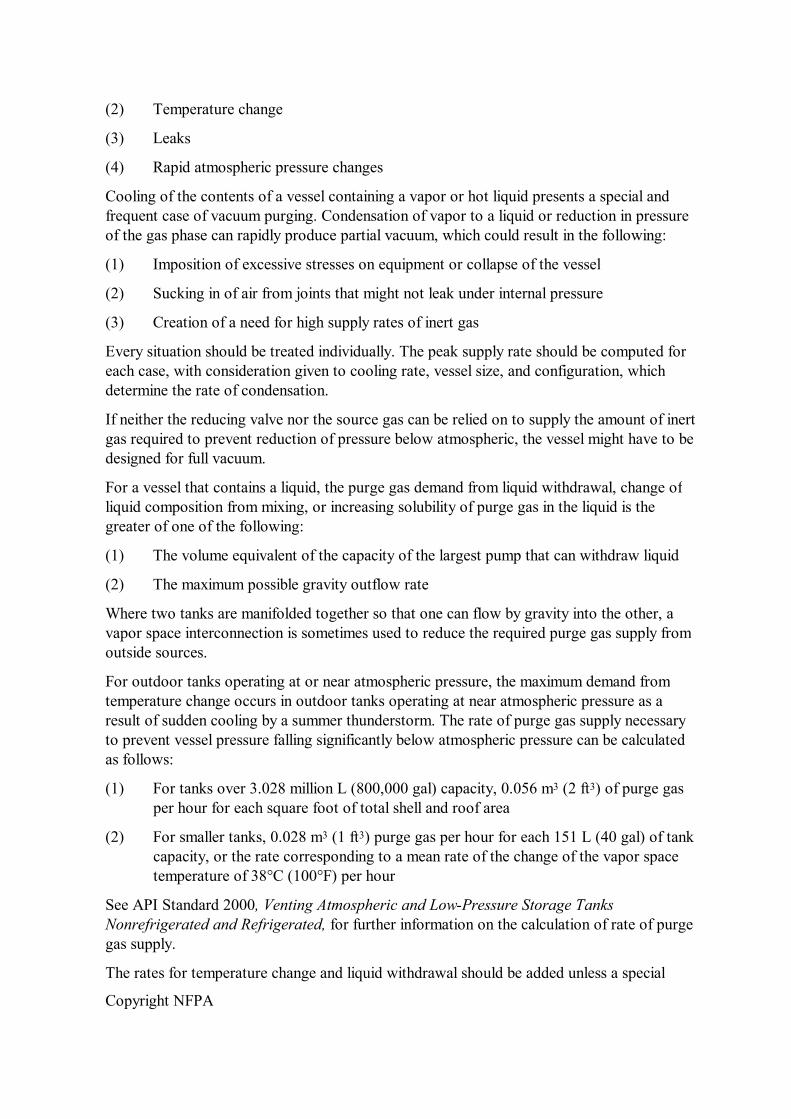
Copyright NFPA
(2) Temperature change
(3) Leaks
(4) Rapid atmospheric pressure changes
Cooling of the contents of a vessel containing a vapor or hot liquid presents a special and frequent case of vacuum purging. Condensation of vapor to a liquid or reduction in pressure of the gas phase can rapidly produce partial vacuum, which could result in the following:
(1) Imposition of excessive stresses on equipment or collapse of the vessel
(2) Sucking in of air from joints that might not leak under internal pressure
(3) Creation of a need for high supply rates of inert gas
Every situation should be treated individually. The peak supply rate should be computed for each case, with consideration given to cooling rate, vessel size, and configuration, which determine the rate of condensation.
If neither the reducing valve nor the source gas can be relied on to supply the amount of inert gas required to prevent reduction of pressure below atmospheric, the vessel might have to be designed for full vacuum.
For a vessel that contains a liquid, the purge gas demand from liquid withdrawal, change of liquid composition from mixing, or increasing solubility of purge gas in the liquid is the greater of one of the following:
(1) The volume equivalent of the capacity of the largest pump that can withdraw liquid
(2) The maximum possible gravity outflow rate
Where two tanks are manifolded together so that one can flow by gravity into the other, a vapor space interconnection is sometimes used to reduce the required purge gas supply from outside sources.
For outdoor tanks operating at or near atmospheric pressure, the maximum demand from temperature change occurs in outdoor tanks operating at near atmospheric pressure as a result of sudden cooling by a summer thunderstorm. The rate of purge gas supply necessary to prevent vessel pressure falling significantly below atmospheric pressure can be calculated as follows:
(1) For tanks over 3.028 million L (800,000 gal) capacity, 0.056 m 3 (2 ft 3 ) of purge gas per hour for each square foot of total shell and roof area
(2) For smaller tanks, 0.028 m 3 (1 ft 3 ) purge gas per hour for each 151 L (40 gal) of tank capacity, or the rate corresponding to a mean rate of the change of the vapor space temperature of 38°C (100°F) per hour
See API Standard 2000, Venting Atmospheric and LowPressure Storage Tanks Nonrefrigerated and Refrigerated, for further information on the calculation of rate of purge gas supply.
The rates for temperature change and liquid withdrawal should be added unless a special
Copyright NFPA
circumstance exists that prevents them from occurring simultaneously.
In some equipment, such as pulverizers, the rate of purge gas supply necessary to exclude air might be dominated by leakage, and temperature change can be ignored.
Annex F Informational References
F.1 Referenced Publications.
The following documents or portions thereof are referenced within this standard for informational purposes only and are thus not part of the requirements of this document unless also listed in Chapter 2.
F.1.1 NFPA Publications. National Fire Protection Association, 1 Batterymarch Park, P.O. Box 9101, Quincy, MA 022699101.
NFPA 51B, Standard for Fire Prevention During Welding, Cutting, and Other Hot Work, 1999 edition.
NFPA 68, Guide for Venting of Deflagrations, 2002 edition.
NFPA 72 ® , National Fire Alarm Code ® , 2002 edition.
NFPA 326, Standard for the Safeguarding of Tanks and Containers for Entry, Cleaning, or Repair, 1999 edition.
Fire Protection Guide to Hazardous Materials, 1997 edition.
F.1.2 Other Publications.
F.1.2.1 API Publications. American Petroleum Institute, 1220 L Street, NW, Washington, DC 20005.
API RP 521, Guide for PressureRelieving and Depressuring Systems, Third Edition, 1990.
API STD 2000, Venting Atmospheric and LowPressure Storage Tanks Nonrefrigerated and Refrigerated, Fourth Edition, 1992.
API 2016, Guidlelines and Procedures for Entering and Cleaning Petroleum Storage Tanks, 2001.
F.1.2.2 USBM Publications. U.S. Bureau of Mines, Columbia Plaza, 2401 E Street, NW, Washington, DC 20241.
Nagy, J., H. G. Dorsett, Jr., and M. Jacobson, Preventing Ignition of Dust Dispersions by Inerting, Report of Investigations 6543, 1964.
Nagy, J., A. R. Cooper, and J. M. Stupar, Pressure Development in Laboratory Dust Explosions, Report of Investigations 6561, 1964.
Nagy, J. and D. J. Surincik, Thermal Phenomena During Ignition of a Heated Dust Dispersion, Report of Investigation 6811, 1966.
F.1.2.3 U.S. Government Publications. U.S. Government Printing Office, Washington, DC
Copyright NFPA
20402.
Title 33, Code of Federal Regulations, Part 154.
F.2 Informational References.
The following documents or portions thereof are listed here as informational resources only. They are not a part of the requirements of this document.
Bartknecht, W., Explosions: Course, Prevention, Protection, SpringerVerlag, Heidelberg, 1981.
L. G. Britton, “Using Heats of Oxidation to Evaluate Flammability Hazards,” March 2002, Process Safety Progress.
Coward, J. F., and G. W. Jones, “Limits of Flammability of Gases and Vapors,” Bulletin 503, U.S. Bureau of Mines, Pittsburgh, PA, 1952.
Eckhoff, R. K., Dust Explosions in the Process Industries, ButterworthHeinemann, Oxford, England, 1991.
Jones, G. W., M. G. Zabetakis, J. K. Richmond, G. S. Scott, and A. L. Furno, “Research on the Flammability Characteristics of Aircraft Fuels,” Wright Air Development Center, WrightPatterson AFB, OH, Technical Report 5235, Supplement I, 1954, 57 pp.
Kuchta, J. M., A. L. Furno, A. Bartkowiak, and G. H. Martindill, “Effect of Pressure and Temperature on Flammability Limits of Chlorinated Combustibles in OxygenNitrogen and Nitrogen TetroxideNitrogen Atmospheres,” Journal of Chemical and Engineering Data, Vol. 13, No. 3, July 1968 (American Chemical Society, Washington, D.C.) p. 421.
Noronha, J. A., J. T. Merry, and W.C. Reid, “Deflagration Pressure Containment for Vessel Safety Design, Plant/Operations Progress,” Vol. 1, No. 1, American Institute of Chemical Engineers, New York, NY, Jan., 1982.
Schuber, G., “Rotary Valves for Explosion Isolation: Approval Without Testing,” European Information Centre for Explosion Protection—International Symposium, Antwerp, Belgium, September, 1989.
Zabetakis, M. G., “Flammability Characteristics of Combustible Gases and Vapors,” Bulletin 627, U.S. Bureau of Mines, Pittsburgh, PA, 1965.
Zabetakis, M. G., and B. H. Rosen, “Considerations Involved in Handling Kerosine,” Proceedings, API, Vol. 37, Sec. III, 1957, p. 296.
F.3 References for Extracts.
The following documents are listed here to provide reference information, including title and edition, for extracts given throughout this standard as indicated by a reference in brackets [ ] following a section or paragraph. These documents are not a part of the requirements of this document unless also listed in Chapter 2 for other reasons.
NFPA 68, Guide for Venting of Deflagrations, 2002 edition.
Copyright NFPA
NFPA 86, Standard for Ovens and Furnaces, 1999 edition.
NFPA 220, Standard on Types of Building Construction, 1999 edition.
NFPA 654, Prevention of Fire and Dust Explosions from the Manufacturing, Processing and Handling of Combustible Particulate Solids, 2000 editions.
F.4 Additional References.
Brennund ExplosionsKenngrossen von Stauben, Berufsgenossenschaftliches Institut fur Arbeitssicherheit (BIA) BergbauVersuchsstrecke, Institut fur Explosionsschutz und Sprengtechnik, Sonderdruck der sicherheitstechnischen.
VDI Richtlinie 3673, Verein Deutscher IngenieureKommission Reinhalting der Luft, Dusseldorf, VDI Verlag GmbH, Dusseldorf, 1979 and 1983.
Zabetakis, M.G., Gasfreeing of Cargo Tanks, Information Circular 7994, U.S. Bureau of Mines, Pittsburgh, PA, 1961.