mu uuuu ui iiui iiui mii iuu mii uui um uui uuii uu uii miu.s. patent jun. 16, 2009 sheet 1 of 10 us...
TRANSCRIPT
mu uuuu ui iiui iiui mii iuu mii uui um uui uuii uu uii mi
(12) United States PatentWinternitz et al.
(54) RADIATION-HARDENED FASTACQUISITION/WEAK SIGNAL TRACKINGSYSTEM AND METHOD
(75) Inventors: Luke Winternitz, Greenbelt, MD (US);Gregory J. Boegner, White Hall, MD(US); Steve Sirotzky, Arlington, VA(US)
(73) Assignee: The United States of America asrepresented by the Administrator ofthe National Aeronautics and SpaceAdministration, Washington, DC (US)
(*) Notice: Subject to any disclaimer, the term of thispatent is extended or adjusted under 35U.S.C. 154(b) by 302 days.
(21) Appl. No.: 11/239,458
(22) Filed: Sep. 20, 2005
(65) Prior Publication Data
US 2006/0082496 Al Apr. 20, 2006
Related U.S. Application Data
(60) Provisional application No. 60/612,396, filed on Sep.20, 2004.
(51) Int. Cl.GOIS 5114 (2006.01)
(52) U.S. Cl . ................................................. 342/357.15(58) Field of Classification Search ............ 342/357.06,
342/357.12, 357.15See application file for complete search history.
(56) References Cited
U.S. PATENT DOCUMENTS
5,404,007 A * 4/1995 Hotaling ..................... 250/2165,459,473 A * 10/1995 Dempster et al. ...... 342/357.12
5,594,453 A 1/1997 Rodaletal.
(1o) Patent No.: US 7,548,199 B2(45) Date of Patent: Jun.16, 2009
6,014,080 A * 1/2000 Layson, Jr .............. 342/357.07
6,211,822 B1 4/2001 Dougherty et al.
6,261,508 131* 7/2001 Featherby et al. ........... 264/408
6,278,404 B1 8/2001 Niles
6,289,041 B1 9/2001 Krasner
6,366,599 B1 4/2002 Carlson et al.6,466,958 131* 10/2002 Van Wechel et al. ........ 708/422
6,735,243 B1 5/2004 Akopian
6,888,879 B1 5/2005 Lennen
(Continued)
OTHER PUBLICATIONS
J. Srinivasan et al., microGPS: On-Orbit Demonstration of a NewApproach to GPS for Space Applications, Proceedings of the IONGPS '98, p. 1537-1545, Sep. 1998.*
(Continued)
Primary Examiner Thomas H TarczaAssistant Examiner Fred H Mull(74) Attorney, Agent, or Firm Matthew Johnston
(57) ABSTRACT
A global positioning system (GPS) receiver and method ofacquiring and tracking GPS signals comprises an antennaadapted to receive GPS signals; an analog radio frequencydevice operatively connected to the antenna and adapted toconvert the GPS signals from an analog format to a digitalformat; a plurality of GPS signal tracking correlators opera-tively connected to the analog RE device; a GPS signal acqui-sition component operatively connected to the analog REdevice and the plurality of GPS signal tracking correlators,wherein the GPS signal acquisition component is adapted tocalculate a maximum vector on a databit correlation grid; anda microprocessor operatively connected to the plurality ofGPS signal tracking correlators and the GPS signal acquisi-tion component, wherein the microprocessor is adapted tocompare the maximum vector with a predetermined correla-tion threshold to allow the GPS signal to be fully acquired andtracked.
26 Claims, 10 Drawing Sheets
RECEIVING GPS SIGNALS YV 51
SUBDIVIDING THE GPS SIGNALS INTO A 53PLURALITY OF FREQUENCY INCREMENTS
PERFORMING A FREQUENCY DOMAIN 55CORRELATION PROCESS ON THE GPS SIGNALS
COMPARING THE CORRELATED GPS SIGNALS ^V57WITH A PREDETERMINED THRESHOLD
ACQUIRING A GPS SIGNAL IF A CORRELATED ^SqGPS SIGNAL EXCEEDS THE PREDETERMINED
THRESHOLD
TRACKING THE ACQUIRED GPS SIGNAL L , 61
https://ntrs.nasa.gov/search.jsp?R=20090043123 2020-06-18T04:31:45+00:00Z

US 7,548,199 B2Page 2
U.S. PATENT DOCUMENTS
7,069,019 B2 * 6/2006 Sahai et al . ............ 342/357.152002/0067307 Al * 6/2002 Lin et al . ............... 342/357.122002/0072853 Al 6/2002 Sullivan2002/0196180 Al * 12/2002 Chang ................... 342/357.062004/0143392 Al 7/2004 Kilfeather et al.2004/0220734 Al 11/2004 Gronemeyer2005/0010362 Al* 1/2005 Dong-Sik ................... 342/3582006/0055596 Al * 3/2006 Bryant et al. .......... 342/357.06
OTHER PUBLICATIONS
Eleanor Ketchum et al., "Modular GPS Review "PiVoT" PeerReview", Nov. 25, 1997, pp. 1-86, Greenbelt, MD, USA.
Mark L. Psiaki, "Block Acquisition of Weak GPS Signals in a Soft-ware Receiver", ION GPS 2001, Sep. 11-14, 2001, pp. 2838-2850,Salt Lake City, UT, USA.Luke Winternitz, "Overview of GPS Signal Processing, Weak SignalIssues, and the PiVoT-2.0 GPS Receiver", Jul. 16, 2003, pp. 1-33,Greenbelt, MD, USA.Luke Winternitz, "Hardware Accelerator FPGA Design Document",DrEvil FPGA, PiVoT2, Revision 0.3, Jul. 16, 2003, pp. 1-20,Greenbelt, MD, USA.Luke Winternitz, "Tracking FPGA Design Document", PowersFPGA, PiVoT2, Revision 0. 1, Jul. 16, 2003, pp. 1-16, Greenbelt, MD,USA.
* cited by examiner
U.S. Patent Jun. 16, 2009 Sheet 1 of 10 US 7,548,199 B2
T- Cl)
U) In
caQ ZOW
Lu
cn
z
J JUa Qz
co N
r co
N W
C7 0 Cy
LL z 2 W
wZ OVW p> J
w a
tiN
JZNO
IL OWC
o=
Q wJZ
OWU~W2wH ^
ZaQ
a~
v
toin
2
NJQ
Z ZQ^OaD ^^- Wv=Z^WZ^O
u-wa^Z ILIL^z^OO^U.^JW WCL w
O0
0) T-U)
DD
Q ? Q
W w Z
WW O
W
V W C9
aw o
U. d WLu J
Z ~_
CO N C1
U)Lu aCL 0 W
X H
Q J z
Z Z Y
^ ^ V
c a
CYa ~
Q C7

Y
OLO9N MNWz
Mx-
N
dLL
U)zOQ W
Z CL N^ 0^Q0v
WaQ o ^Q TQO
Wa ^^
N G NoQ
qqN2O t°^w
W^aLU?WQ^^
0z Q
ti
U.S. Patent
Jun. 16, 2009
Sheet 2 of 10
US 7,548,199 B2
of
U^NV,
OI
V ^

Q LO C) LO
1/fir
+
ropSs01 1
QT
8PSS0l
1 1 N
C 1r Ni 1
^ T
N 1
Q LO1
U.S. Patent Jun. 16, 2009
Sheet 3 of 10 US 7,548,199 B2
T N
00
O LOT
'M_VLL
ci
0
NO
C? LU
4NO
E
C)
1
flo
T
LQ0
I--
OZt
d
1
T
LqT

0r 00
U.S. Patent Jun. 16, 2009 Sheet 4 of 10 US 7,548,199 B2
C?u-
v
a?
EC04-^s0
C
ca)0 ^00
N
aLOV-
N
N
r d) CO CO tfj .p m N r
0 o Ca o 0 0 0 o a
00 ^-
ad

U.S. Patent Jun. 16, 2009 Sheet 5 of 10 US 7,548,199 B2
C)T
NC)V-
C)N
C)T
UNin4?E
CD C:O O
C3?v
c
0
t; 7T
N
to
Lt's
0LL
im
LON
.-- 0) co P,- (D LO I;T M N T-
O O C? O O o Q 0
ad
u N
O °

#
L ^V
,w
- # O
a ^-N#
Qi#
# to cn= ^ c c
O O
U U(1) N
#
O N N-C4 4+
Ic ^
#
w
4MN.gyi'^HiC@ Wq
LOTO
V
LL
Qu-
CNO
U')O
O
O
U.S. Patent Jun. 16, 2009 Sheet 6 of 10 US 7,548,199 B2
•- O QO ^ CQ to et CO N T- rnO m O O W O m O O OO O CO O O O O O O
ad

U.S. Patent Jun. 16, 2009 Sheet 7 of 10 US 7,548,199 B2
LOU)U)VL
OC
Oe-
•v OE
1` ^ LC
n OOAW ♦•+
LMO
crVH O
V Q
OWr
=CQ
0
LL
= OOf+
r
QrOr

U.S. Patent Jun. 16, 2009 Sheet 8 of 10 US 7,548,199 B2
Nr
Tr
C)T
rWV_ VJ ^
co
r—
JLO 00 w ;:T (N I' 00 CD
NC+7 M
(8p) ui6jew uoilisinboe

U.S. Patent Jun. 16, 2009
Sheet 9 of 10 US 7,548,199 B2
..................................
_ a° T-
aCL '°T OE 1- 0
as ° L
O a .n U Q
n E L
HX LLLL
^O T N
•aL ;72.•
n LL•
TT T •
O r n
T T •n ^ Tn LL• LL
nO: T •
S. n . n nn ... nn
. n ........ n ... n ......a
N0
P - -
I
- - - - - - - -
I
1 L OC 02 E 1
+.. 0 0
1 aoLL
Ec°>ET
IO t t 0 T I
" OV T
It o
a, I
0I T C I
co NT
_ T
IY +
la Ic6O^
N "°0 cam°'O O ENI T " I
I
I
— — —
I
I
— d
I
-- — — — —

U.S. Patent Jun. 16, 2009 Sheet 10 of 10 US 7,548,199 B2
U
L ^ U
O WO 0^ N ^°_
NUO WL Z
o N0 w 0 .^ 0CU E mC '> s ^
N Ncaz Q'
wQ
ca
O cnL
_32 o N0 co
0D'V
Q Pipe-wall
Q E
\iaai
Ei
CL vLL. c
0 N iL Ln U
'=3 0cr cQ U
c ^ c
0
U.
US 7,548,199 B21 2
RADIATION-HARDENED FAST ingly, there remains a need for a new, fully space-qualifiedACQUISITION/WEAK SIGNAL TRACKING weak signal GPS receiver targeted for high altitude applica-
SYSTEM AND METHOD tions.
CROSS-REFERENCE TO RELATEDAPPLICATION
5 SUMMARY
This application claims the benefit of U.S. ProvisionalPatent Application No. 60/612,396 filed on Sep. 20, 2004,which is herein incorporated by reference in its entirety.
GOVERNMENT INTEREST
The embodiments of the invention described herein weremade by employees of the United States Government, andmay be manufactured and used by or for the United StatesGovernment for governmental purposes without payment ofany royalties thereon or therefor.
BACKGROUND
1. Field of the InventionThe embodiments of the invention generally relate to sig-
nal processing and, more particularly, to techniques for signalacquisition and tracking.
2. BackgroundGlobal positioning systems (GPS) have found wide appli-
cation for precision spacecraft navigation and formation fly-ing applications in Low Earth Orbits (LEO), but recentadvances in GPS receiver designs and signal processing capa-bilities now make it feasible to consider using GPS to provideautonomous, onboard navigation capabilities for geostation-ary (GEO) or other high altitude space missions.
Conventional (GPS) receivers are generally not readilycapable of operating effectively at altitudes above LEO. Thisis primarily due, in part, to the fact that the GPS signalsavailable there are approximately 10-100 times weaker muchmore sparsely present than on Earth or at LEO. However, GPSreceivers typically provide a very accurate and economicalmeans of navigation and have become very popular for LEOmissions and could be just as popular for High Earth Orbit(HEO-above LEO) missions if the technology were available.
Generally, GPS signal processing can be divided into twomajor tasks: signal acquisition (or detection) and then signaltracking (and demodulation). Signal acquisition is the pro-cess of finding a GPS signal within a two-dimensionalunknown parameter space. Signal tracking is the process ofcontinuously updating the estimates of these two and othersignal parameters. Signal acquisition is generally a more dif-ficult process than signal tracking, and it is the inadequacy ofconventional GPS acquisition techniques that generally pre-vents the use of weak signals in GPS receivers.
The generally inadequate (for weak signals) conventionalapproach is to employ a serial search of the two-dimensionalparameter space during acquisition. Typically, the same hard-ware that is used in signal tracking is reconfigured to affect thesearch. During a cold-start, which is a lack of any prior (apriori) information about visible GPS signals, acquisition byserial search can take upwards of 20 minutes for a very strongsignal. To acquire weak signals, more data must be examined.Approximately 10 times the data record length is required fora 10 times weaker signal. Using serial search methods acqui-sition times grow quadratically, which results in a 20-minutesearch increasing to approximately 33 hours, which practi-cally means that the signal cannot be acquired at all. Accord-
Disclosed herein is a global positioning system (GPS)receiver comprising a GPS signal acquisition componentincluding a frequency domain correlation module, wherein
10 said GPS signal acquisition component is adapted to acquiresaid GPS signal with an Effective Isotropic Received Power(EIRP) of at least about —180 dBW, and wherein said GPSreceiver is adapted to operate in a space environment. TheGPS receiver may further comprise a plurality of GPS signal
15 tracking correlators adapted to track said GPS signals with anEIRP of at least about —175 dBW. The GPS signal trackingcorrelators may comprise a Field-Programmable Gate Array(FPGA). The GPS signal acquisition component also maycomprise an FPGA. The GPS signal acquisition component
20 may be adapted to acquire a GPS signal within about oneminute for GPS signals with an EIRP greater than about —180dBW. The GPS signal acquisition component may be adaptedto acquire a GPS signal within about one second for GPSsignals with an EIRP greater than about —160 dBW. The GPS
25 signal acquisition component alternately may be adapted toacquire a GPS signal within about one minute for GPS signalswith an EIRP greater than about —180 dBW, and to acquire aGPS signal within about one second for GPS signals with anEIRP greater than about —160 dBW. The GPS signal acqui-
30 sition component may be adapted to perform a Fast FourierTransform (FFT) correlation process on said GPS signals.The GPS signal acquisition component may be adapted toacquire a GPS signal without a priori data.
Also disclosed heroin is a GPS receiver comprising a GPS35 signal acquisition component including a frequency domain
correlation module, wherein said GPS signal acquisitioncomponent is adapted to acquire a GPS signal within aboutone second for GPS signals with an EIRP greater than about—160 dBW, and wherein said GPS receiver is adapted to
40 operate in a space environment. The GPS receiver may furthercomprise a plurality of GPS signal tracking correlatorsadapted to track said GPS signals with an EIRP of at leastabout —175 dBW. The GPS signal tracking correlators mayalso comprise an FPGA. The GPS signal acquisition compo-
45 nent optionally may comprise an FPGA. Also, the GPS signalacquisition component may comprise a frequency domaincorrelation module. The GPS signal acquisition componentmay be adapted to acquire a GPS signal with an EIRP greaterthan about —180 dBW. The GPS signal acquisition compo-
5o nent may be adapted to acquire a GPS signal within about oneminute for GPS signals with an EIRP greater than about —180dBW. The GPS signal acquisition component may be adaptedto perform an FFT correlation process on said GPS signals.Alternately, the GPS signal acquisition component may be
55 adapted to acquire a GPS signal without a priori data for GPSsignals with an EIRP greater than about —180 dBW.
Also disclosed herein is a GPS receiver comprising a GPSsignal acquisition component including a frequency domaincorrelation module, wherein said GPS signal acquisition
60 component is adapted to acquire said GPS signals with anEIRP of at least about —180 dBW without a priori data, andwherein the acquired GPS signal is acquired substantially inreal time. The GPS receiver may further comprise a pluralityof GPS signal tracking correlators adapted to track said GPS
65 signals with an EIRP of at least about —175 dBW. The GPSsignal tracking correlators also may comprise an FPGA. TheGPS signal acquisition component may comprise an FPGA.

US 7,548,199 B23
The GPS signal acquisition component may be adapted toacquire a GPS signal within about one minute for GPS signalswith an EIRP greater than about —180 dBW. The GPS signalacquisition component may be adapted to acquire a GPSsignal within about one second for GPS signals with an EIRP 5
greater than about —160 dBW. The GPS signal acquisitioncomponent may be adapted to acquire a GPS signal withinabout one minute for GPS signals with an EIRP greater thanabout —180 dBW and to acquire a GPS signal within aboutone second for GPS signals with an EIRP greater than about io—160 dBW. The GPS signal acquisition component may beadapted to perform an FFT correlation process on said GPSsignals. The GPS signal acquisition component may beadapted to acquire a GPS signal without a priori data.
Also disclosed herein is a method of acquiring and tracking 15
GPS signals, comprising the steps of: receiving GPS signals;performing a frequency domain correlation process on saidGPS signals; comparing the correlated GPS signals with apredetermined threshold; and acquiring a GPS signal if acorrelated GPS signal exceeds the predetermined threshold. 20
The step of performing a frequency domain correlation pro-cess may comprise performing an FFT correlation process fora plurality of frequency increments of the received GPS sig-nals. The step of acquiring a GPS signal may comprise acquir-ing the GPS signal if a correlated GPS signal exceeds the 25
predetermined threshold for any of the frequency increments.The method of acquiring and tracking GPS signals furthermay comprise receiving GPS signals for a plurality of timeincrements, and accumulating the correlated GPS signalsover a plurality of time increments to permit the acquisition of 30
GPS signals with substantially lower received EIRP. Each ofthe plurality of time increments preferably is about 1 ms. Themethod further may comprise acquiring said GPS signals atan EIRP of at least about —180 dBW. The method further maycomprise tracking said GPS signals at an EIRP of at least 35
about —175 dBW. The method further may comprise acquir-ing a GPS signal within about one minute for GPS signalswith an EIRP greater than about —180 dBW. The methodfurther may comprise acquiring a GPS signal within aboutone second for GPS signals with an EIRP greater than about 40
—160 dBW The method further may comprise acquiring aGPS signal with an EIRP greater than about —180 dBWwithin about one minute and acquiring a GPS signal with anEIRP greater than about —160 dBW within about one second.The method further may comprise acquiring a GPS signal 45
with an EIRP greater than about —180 dBW without a prioridata.
Also disclosed herein is a method of acquiring and trackingGPS signals, comprising the steps: receiving GPS signals fora plurality of time increments; performing a frequency 50
domain correlation process on said GPS signals for each ofthe plurality of time increments; comparing the correlatedGPS signals with a predetermined threshold; and acquiring aGPS signal if a correlated GPS signal exceeds the predeter-mined threshold for any of the plurality of time increments. 55
Each of the plurality of time increments preferably is about 1ms. The step of performing a frequency domain correlationprocess may include performing an FFT correlation processfor a plurality of frequency increments of the received GPSsignals for each of the plurality of time increments. The step 60
of acquiring The GPS signal may include acquiring a GPSsignal if a correlated GPS signal exceeds the predeterminedthreshold for any of the frequency increments for any of thetime increments. The method further may comprise acquiringa GPS signal with an EIRP of at least about —180 dBW. The 65
method further may comprise tracking a GPS signal with anEIRP of at least about —175 dBW. The method further may
4comprise acquiring a GPS signal with an EIRP greater thanabout —180 dBW within about one minute. The method fur-ther may comprise acquiring a GPS signal with an EIRPgreater than about —160 dBW within about one second. Themethod further may comprise acquiring a GPS signal withinabout one minute for GPS signals with an EIRP greater thanabout —180 dBW and acquiring a GPS signal within about onesecond for GPS signals with an EIRP greater than about —160dBW. The method further may comprises acquiring a GPSsignal with an EIRP greater than about —180 dBW without apriori data.
Also disclosed herein is a computer program embodied ina computer readable medium for acquiring and tracking GPSsignals, which comprises a receiver module for receivingGPS signals, a correlation module for performing a frequencydomain correlation process on said GPS signals, a compari-son module for comparing the correlated GPS signals with apredetermined threshold, and an acquisition module foracquiring a GPS signal if a correlated GPS signal exceeds thepredetermined threshold to allow said GPS signal to beacquired and tracked. The correlation module may be adaptedto perform the frequency domain correlation process by con-trolling a hardware acquisition component. The hardwareacquisition component may comprise an FPGA. The com-puter readable medium may be radiation hardened. Thereceiver module may be adapted to receive GPS signals forone or more time increments. The frequency domain corre-lation process may comprise an FFT correlation process for aplurality of frequency increments of the received GPS signalsfor each of the one or more time increments. The acquisitionmodule may be adapted to acquire a GPS signal if the corre-lated GPS signal exceeds the predetermined threshold for anyof the frequency increments for any of the one or more timeincrements. The acquisition module may be adapted toacquire GPS signals with an EIRP of at least about —180dBW. The computer program further may comprises a track-ing module for tracking GPS signals with an EIRP of at leastabout —175 dBW. The acquisition module may be capable ofacquiring a GPS signal with an EIRP greater than about —180dBW within about one minute. The acquisition module maybe capable of acquiring a GPS signal with an EIRP greaterthan about —160 dBW within about one second. The receivermodule may receive GPS signals via a hardware receiver.
The present invention overcomes the problems and disad-vantages associated with conventional methods and systems,and provides improved systems and methods for fast signalacquisition and weak signal tracking.
Other embodiments and advantages of the invention are setforth in part in the description that follows, and in part, will beobvious from this description, or may be learned from thepractice of the invention.
BRIEF DESCRIPTION OF THE DRAWINGS
The embodiments of the invention will be better under-stood from the following detailed description with referenceto the drawings, in which:
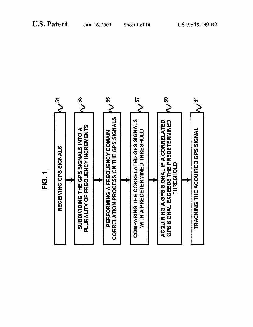
FIG. 1 is a flow diagram illustrating a preferred methodaccording to an embodiment of the invention;
FIG. 2 is a computer architecture diagram according to anembodiment of the invention;
FIG. 3 illustrates graphical representations of ambiguityfunction cross-sections according to an embodiment of theinvention;
FIGS. 4 and 5 illustrate graphical representations of per-formance curves according to an embodiment of the inven-tion;

US 7,548,199 B25
FIG. 6 illustrates graphical representations of receiveroperating characteristic (ROC) curves according to anembodiment of the invention;
FIG. 7 illustrates a system block diagram according to anembodiment of the invention;
FIG. 8 illustrates a graphical representation of an output ofa simulation testing an embodiment of the invention;
FIG. 9 illustrates a dual mode acquisition block diagramaccording to an embodiment of the invention; and
FIG. 10 illustrates a software/hardware interface schematicdiagram according to an embodiment of the invention.
DETAILED DESCRIPTION
The embodiments of the invention and the various featuresand advantageous details thereof are explained more fullywith reference to the non-limiting embodiments that are illus-trated in the accompanying drawings and detailed in the fol-lowing description. It should be noted that the features illus-trated in the drawings are not necessarily drawn to scale.Descriptions of well-known components and processingtechniques are omitted so as to not unnecessarily obscure theembodiments of the invention. The examples used herein areintended merely to facilitate an understanding of ways inwhich the embodiments of the invention may be practiced andto further enable those of skill in the art to practice theembodiments of the invention. Accordingly, the examplesshould not be construed as limiting the scope of the embodi-ments of the invention.
As mentioned, there remains a need for a new, fully space-qualified weak signal GPS receiver targeted for high altitudeapplications. The embodiments of the invention achieve thisby providing a space-borne GPS receiver that can operateeffectively in the full range of Earth orbiting missions fromLEO to GEO and beyond. Specifically, the embodiments ofthe invention provide a fully space flight qualified GPSreceiver optimized for fast signal acquisition and weak signaltracking. The fast acquisition capabilities provide exceptionaltime to fix performance with no a priori receiver state or GPSalmanac information, even in the presence of high Dopplershifts present in LEO (or near perigee in highly eccentricorbits). The fast acquisition capability also makes it feasibleto implement extended correlation intervals and thereforesignificantly reduce the acquisition threshold of the embodi-ments of the invention. This greatly improves GPS observ-ability when the receiver is above the GPS constellation (andsatellites must be tracked from the opposite side of the Earth)by providing at least about 15 dB of increased acquisitionsensitivity. One of skill in the art will recognize that thepresent invention, while particularly advantageous for space-based applications, from LEO to GEO and beyond, is notlimited to the particular embodiments enclosed herein andcan also be applied to other applications known to those ofskill in the art where weak signal acquisition and tracking orfast signal acquisition are desireable. Some exemplaryembodiments of the present invention are disclosed in thepaper Luke Winternitz, et al, "Navigator GPS Receiver forFast Acquisition and Weak Signal Tracking Space Applica-tions," Proceedings of the Institute of Navigation GNSS 2004Conference, Long Beach, Calif. September 2004, which isherein incorporated by reference in its entirety.
Referring now to the drawings, and more particularly toFIGS. 1 through 10, where similar reference charactersdenote corresponding features consistently throughout thefigures, there are shown preferred embodiments of the inven-tion.
6FIG. 1 is a flow diagram illustrating a method of acquiring
and tracking GPS signals according to an embodiment of theinvention, wherein the method comprises receiving (51) GPSsignals; subdividing (53) the GPS signals into a plurality of
5 frequency increments; performing (55) a frequency domaincorrelation process on a plurality of the frequency incrementsof said GPS signals; comparing (57) the correlated GPS sig-nals with a predetermined threshold; and acquiring (59) aGPS signal if a correlated GPS signal exceeds the predeter-
io mined threshold for any of the frequency increments of a GPSsignal. The method optionally further includes tracking (61)the acquired GPS signal The step of performing a frequencydomain correlation process preferably comprises performinga Fast Fourier Transform (FFT) correlation process to corre-
15 late the GPS signals.Furthermore, the method may further comprise acquiring
GPS signals at an EIRP of at least about —180 dBW; andtracking the GPS signals at an EIRP of at least about —180dBW. Moreover, the method may further comprise fast acqui-
20 sition of a GPS signal within about one second for GPSsignals with an EIRP greater than about —160 dBW. In yetanother embodiment, the method comprises fast acquisitionof weak GPS with an EIRP greater than about —180 dBWwithin about one minute. One of skill in the art will recognize
25 that a GPS receiver capable of fast acquisition of both strongand weak signals falls within the scope of the present inven-tion. In yet another embodiment, the method may furthercomprise acquiring a GPS signal with an EIRP greater thanabout —180 dBW. without a priori data. One of skill in the art
so will recognize that the present invention permits acquisitionof GPS signals more quickly for signals with higher receivedEIRP with no prior knowledge of the GPS signal.
Additionally, the method may further comprise acquiring aGPS signal within about one minute for GPS signals with an
35 EIRP greater than about —180 dBW. The method optionallymay further comprise combining the shifted GPS signalsoutput by the FFT correlation process with a pre-computed,conjugated Discrete Fourier Transform (DFT) output. Addi-tionally, the method preferably comprises performing an
40 Inverse Fast Fourier Transform of the combined GPS signalsand DFT output.
The embodiments of the invention can take the formincluding bothhardware and software elements. The softwareembodiment includes but is not limited to firmware, resident
45 software, microcode, etc. Furthermore, the embodiments ofthe invention can take the form of a computer programembodied in a computer-readable medium providing pro-gram code for use by or in connection with a computer or anyinstruction execution system. For the purposes of this
5o description, a computer-usable or computer readable mediumcan be any apparatus that can comprise, store, communicate,propagate, or transport the program for use by or in connec-tion with the instruction execution system, apparatus, ordevice.
55 The medium can be an electronic, magnetic, optical, elec-tromagnetic, infrared, or semiconductor system (or apparatusor device) or a propagation medium. Examples of a computer-readable medium include a semiconductor or solid-statememory, magnetic tape, a removable computer diskette, a
6o random access memory (RAM), a read-only memory (ROM),a rigid magnetic disk and an optical disk. Current examples ofoptical disks include compact disk read only memory (CD-ROM), compact disk read/write (CD-R/W) and DVD. Oneof skill in the art will recognize that the foregoing types of
65 computer readable media are merely exemplary and that othertypes of computer readable media are contemplated by thepresent invention.

US 7,548,199 B27
A data processing system suitable for storing and/orexecuting program code preferably will include at least oneprocessor coupled directly or indirectly to memory elementsthrough a system bus. The memory elements can include localmemory employed during actual execution of the programcode, bulk storage, and cache memories which provide tem-porary storage of at least some program code in order toreduce the number of times code must be retrieved from bulkstorage during execution.
Input/output (I/O) devices (including but not limited tokeyboards, displays, pointing devices, etc.) can be coupled tothe system either directly or through intervening I/O control-lers. Network adapters may also be coupled to the system toenable the data processing system to become coupled to otherdata processing systems or remote printers or storage devicesthrough intervening private or public networks. Modems,cable modem and Ethernet cards are just a few of the currentlyavailable types of network adapters.
A representative hardware environment for practicing theembodiments of the invention is depicted in FIG. 2. Thisschematic drawing illustrates a hardware configuration of aninformation handling/computer system in accordance withthe embodiments of the invention. The system comprises atleast one processor or central processing unit (CPU)10. TheCPUs 10 are interconnected via system bus 12 to variousdevices such as a random access memory (RAM) 14, read-only memory (ROM) 16, and an input/output (I/O) adapter18. The I/O adapter 18 can connect to peripheral devices, suchas disk units 11 and tape drives 13, or other program storagedevices that are readable by the system. The system can readthe computer program on the computer readable media andexecute the computer program to implement the methodol-ogy of the embodiments of the invention. The system furthermay include a user interface adapter 19 that connects a key-board 15, mouse 17, speaker 24, microphone 22, and/or otheruser interface devices such as a touch screen device (not
shown) to the bus 12 to gather user input. Additionally, acommunication adapter 20 may connect the bus 12 to a dataprocessing network 25, and a display adapter 21 connects thebus 12 to a display device 23 which may be embodied as anoutput device such as a monitor, printer, or transmitter, forexample.
Another embodiment of the invention provides aGPSreceiver adapted for use in a space environment. In yetanother embodiment, the GPS receiver may be adapted foroperation in LEO orbit, a GEO orbit, or a variety of orbitalconditions above or below GEO orbit. The GPS receiver maybe fully space flight qualified using radiation-hard parts.Another embodiment preferably implements methodologiesor algorithms in field-programmable gate arrays (FPGAs) toallow for easy modification, upgrading, and customization.Alternately, the method of the present invention may beimplemented in one or moreASICs. One of skill in the art willrecognize that a variety of hardware combinations fall withinthe scope of the present invention.
Another embodiment provides a GPS receiver which canacquire and track signals at an EIRP of —180 dBW. Anotherembodiment of the invention provides a GPS receiver capableof acquiring GPS signals within about one second for strongsignals (with an EIRP greater than —160 dBW) and oneminute for weak signals (with an EIRP greater than —180dBW). One of skill in the art will recognize that the presentinvention permits acquisition of GPS signals more quickly forsignals with higher received EIRP with or without a prioriknowledge of the GPS signals.
The embodiments of the present invention provide perfor-mance improvements over the conventional receivers: (1)
8signals can be reliably acquired and tracked down to areceived EIRP of about —180 dBW, which is at least a 15 dBimprovement in sensitivity; and (2) Fast Fourier Transform(FFT) based acquisition algorithms provide extremely short
5 acquisition times even for the weakest signals.In order to make use of a GPS signal coming from a
particular satellite, a GPS receiver first acquires and thentracks the signal. Again, the acquisition process is a muchmore computationally demanding task than the tracking pro-
mo cess, requiring a search across a three-dimensional space ofunknown time delay, Doppler shift, and satellite number. It isalso a limiting factor for sensitivity for the common GPSreceiver architecture. The acquisition methodologies imple-mented in the embodiments of the invention may be adapted
15 from the weak GPS signal acquisition technique provided byPsiaki, M. L., `Block Acquisition of Weak GPS Signals in aSoftware Receiver," ION GPS 2001, 11-14 Sep. 2001, SaltLake City, Utah, the complete disclosure of which, is hereinincorporated by reference in its entirety. Psiaki presents a
20 detection statistic and hypothesis testing scheme that enablesthe acquisition of very weak GPS signals with no a prioriknowledge; in particular, no knowledge of the GPS data mes-sage bits. An embodiment of the present invention employsthe methodologies taught in Psiaki using specialized hard-
25 ware implemented in radiation-hardened FPGAs. In anotherembodiment, the acquisition process is capable of runningsubstantially in real-time. For the purposes of this embodi-ment, substantially in real time means that the signal param-eters of the acquired signal are valid for tracking purposes
30 when acquired. In another embodiment, the GPS receiver iscapable of achieving the desired sensitivity with acquisitiontimes of only a few seconds.
The received, down converted and sampled GPS signal canbe preferably modeled as:
35
Yk=sk+nk k=1,2,... (1)
sk \
Ad( kT —r`I
I/ kT — r C AT
k k=Ad c Cp"T^40 1+ n /\ 1+ n
A = IAIe'a = c- T eta , nk — CN(0, c-2)0
45 Computationally, the received signal is yk, comprising thesum of the GPS signal, sk, and complex white Gaussian noise,nk (real and imaginary part of nk are N(O, c^/2) and indepen-dent). Here, d(.) is the 50 bps GPS data message and c(.) is the1.023 Mcps, 1 ms (1023 chip) periodic Pseudo Random
5o Noise (PRN) spreading code, both taking values in {-1,+1 }.Moreover, A comprises the complex GPS signal amplitude/phase, which is related to the received C/N, as shown with Ts,which comprises the sampling period in seconds. Moreover,w connotes the Doppler shift inrad/s and q —w/ L 57542x 109 is
55 the unitless Doppler compression factor on the PRN code.Additionally, ti represents the time delay in the seconds mod-ule and is approximately 0.001 sec. Furthermore, ck and dk arethe appropriately compressed and delayed code and datasamples (ck(i) is denoted when it is desired to make depen-
60 dence on ti explicit). The noise can be modeled as whitebecause it is assumed that the signal is bandpass filtered tocapture only the mainlobe and then sampled at the Nyquistrate for the resulting bandwidth.
For simplicity, it preferably is first assumed that there is65 only one known satellite signal potentially present and the
data modulation d(.) is ignored. Then, GPS signal acquisitioncomprises determining whether this signal is present and, if
US 7,548,199 B29
so, at which point, (w,T). Given a finite set of samples, y—(yo,yv • • • y,--,) (s, n defined analogously), it is desired to testbetween the following hypotheses, and if H, is accepted,(w,T) is preferably estimated as:
Ho:y=np1A1=0
H1 : y=s+nom 1 A 1 >0 (2)
The signal, s, may depend on a number of unknown param-eters (A,W,i) which lie in some known space. The true valuesof these parameters are denoted as: (A.),w.,i.). Because ofthese unknowns, no clear optimal test generally exists underany common criteria. One approach is to use a GeneralizedLikelihood Ratio Test (GLRT). This procedure will usuallyproduce the optimal test if it exists and otherwise generallygives effective sub-optimal testing procedures. The GLRTprescribes the following test:
GLR = sup,,,)ft (Y; A , w, T) > (3)
fo(Y)Y
Here, f (.) denotes the joint probability density of the dataunder hypothesis H i . That is, the ratio of the correspondingjoint probability densities of the data under each hypothesis iscomputed, with the observed data substituted in (the likeli-hoods). Then, H, is decided if this ratio exceeds some thresh-old, which is preferably chosen to fix or bound the false alarmprobability, Pf,As, using the Neyman-Pearson (NP) criterion.Unknown parameters preferably are replaced by their maxi-mum likelihood (ML) estimates under H i . The ML estimateofA may easily be determined (as a function of w and ti) to be:
10is declared at that particular (w,T). In the serial search newdata is used at each grid point. This amounts to performing anindependent binary test at each grid point with (w,ti) known(thus no need to estimate them). In fact, if phase is treated as
5 random and uniformly distributed in (0, 27t), this is a preferred(Uniformly Most Powerful for Al >0) test under the NP andBayes criteria. In this case, there is no maximization and thestatistics of Z, from Equation (5), completely, specify theperformance of the test. The false alarm probability prefer-
10 ably is set for the individual tests and thus is actually the falsealarm rate. This rate can be traded off against the detectionprobability. In the serial search false alarms slow the acqui-sition process, but are not devastating because the trackingeventually fails when initialized with a false signal. After the
15 failure, acquisition can continue where it is left off.In the parallel search, a single block of data is used to
maximize IZI over the test grid. Although the same computa-tions are performed as in the serial case (only on a fixed blockof data rather than new blocks), the problem is statistically
20 very different. In this case, the test statistic is max1Z1 whoseexact distribution is very difficult to obtain since there is adependence between the correlations across the search grid.The "(W,i) known" statistics, which fully characterize theserial test, can be used in the parallel case to obtain bounds on
25 the false alarm probability as well as the approximate perfor-mance.
One method for controlling Pf,A, in the parallel search, isvia the union bound. Here, one preferably divides the desiredoverall false alarm probability by the number of grid points
30 and uses that to set the threshold assuming (W,i) known. Inanother embodiment, one can assume:
1 N-1A ML(&) , T)=
N ,Yk Ck^ J^kTs
k=0
Pr(ma^Z(&), T)I > Y) ^ Pr(ma^Z(a) , 7`)I > Y) (6)(4) 35 (W,,) (W',,')
I A IML = IAMLI, OML = LAML
The maximization of Equation (3) over (W,i) may be per-formed by a grid search over the range of allowable values:(W,i) in [w_,,,, w_1x10,0.001].It can be shown by substitut-ing in the corresponding multivariate Gaussian densities, thatEquation (3) reduces to the familiar test on the correlationstatistic (scaling term included to normalize the noise):
maN.,,) IZ(.,,)(Y)I > Y (5)
2 N-1
_
Z(^,r)(Y)= N^2 ^Yk ^kC yT
=0
That is, one looks for the maximum magnitude-squared,over (w,ti), of the correlation between the input and a unitamplitude, zero-phase replica of the signal and compares itagainst a threshold. This is equivalent to comparing the fullML estimate of the signal amplitude against a threshold,which is intuitively satisfying.
The test described above preferably utilizes the calculationof correlation at each (w,ti) using the same set of inputsamples. This is referred to as the parallel search. In contrast,most conventional GPS receivers typically employ a serialsearch. The local signal generator serially steps through the(w,ti) grid and computes a correlation with the input samples,as the data streams in. When a threshold is crossed, a detection
where the (W',i') are the mutually independent points on thegrid. There are approximately
4o Ki„aP-1023*DopplerRange*NT, of these independentpoints. With independence, one can solve for the exact thresh-old for a given Pf,A . Using Pf,AIKi„a p in the (w,ti) known testprovides a very good approximation to the desired threshold.
False alarms are generally less tolerable in the parallel45 case. There is a range of threshold values where there is a very
high probability that at the true signal point, Z(W,,io) willexceed the threshold, and so the signal should eventually bedetected by the serial search. However, there is also a rela-tively large false alarm rate and a large probability that Z(wo,
50 tio) is not the largest correlation over the grid. One way to lookat it is that the correct decision, H 1 , is made, but the estimationOf (W,i) is bad. This is referred to as a "Type III" error, asopposed to false alarms under Ho or "Type I" errors, andmissed detections under H, or "Type II" errors. Another
55 approach to this problem is as an M-ary test with H(-,,):"signal present at (W,i)", wherein similar results can beobtained.
One of the problems with a serial search is that the serialsearch process, where new data is used in each correlation,
60 takes too long for weak signals. For example, using N corre-sponding to 1 ms typically allows for a best-case acquisitionof signals of about 35 dB-Hz, which corresponds to an EIRPof approximately —165 dB W, (with many false alarms). In thi scase, the time to first fix performance (TTFF) could be on the
65 order of about 30 min. If one desires a 10 times improvementin sensitivity, one could increase the N to 10 ms, but inaddition one also has to increase the fineness of the grid in the

1,17- 1 2 sin(OmT N / 2) 2RIOT, 0)12 ^1- TA,
, I R (0 , 0012 = Nsin(Aw T/2)
30 M-1
s) Q(.") _ Y, IZ(.,T),m12m=0
Q^ = maNw,T) Q(w,T)
(l0)
US 7,548,199 B2
where (Aw, AT)=(w-w o, ti-tio) comprise the errors in estimat-ing (W,i), and 0 (tilde) comprises the phase of R(Aw,Ati). ThisR(Aw,Ati) (which approximately depends only on Ai) issometimes referred to as the ambiguity function, and it gen-erally specifies the necessary fineness of the grid upon whichthe maximization of Equation (4) is performed. Uncertaintyor error in the estimates of w and ti result in a reduced mean ofthe correlation statistic and can be viewed as a decrease of theeffective input C/No . The cross sections of R(.,.), which areplotted in FIG. 3 are given by the following equations:
12divided down by 1023 (appropriate for search across all codedelays and a 1 kHz Doppler range) are shown in FIG. 4, withPD vs. coherent integration time (W,i) known and P,.,-0.05/1023. Here, a factor of 10 increase in integration time gener-
5 ally results in a 10 dB increase in sensitivity.Unfortunately, the 20 ms GPS databit limits how long the
coherent integration can run (other effects such as signal andclock dynamics limit this time as well but on a longer scalethan 20 ms). Correlating over a databit transition may result in
io unpredictable cancellation of correlation power. Even using20 ms generally requires knowledge of the bit start times. Thebit start time could be added to the problem as an unknownparameter and one could further maximize Equation (3) overthe additional dimension. Generally, a single 20 ms coherent
15 correlation generally will not reliably detect the desired 25dB-Hz signal (corresponding to an EIRP of approximately-175 dBW), accordingly, what is needed is a way to extendthe correlations beyond the databits.
One embodiment capable of solving the problem is the20 "half-bits" method, which collects consecutive 10 ms corre-
lations. If one looks at this collection as two alternating sets,then, one is guaranteed to be free of transitions. A collectionof M 10 ms (or any arbitrary L ms not necessarily equal to 10)coherent correlations that individually avoid databit transi-
25 tions, {Z(„ T) ms m=1,2 ... L}, can be combined "non-coher-ently" by taking the magnitude squared and then summing.This removes the problematic databit.
11frequency dimension by another factor of 10. This implies anew TIFF on the order of about 3,000 min. Accordingly, thesearch preferably is parallelized. In either case, a rather largenumber of correlations need to be quickly computed.
The following results from computing Equation (4):
N-1 (7)
Z(., T)(.Y) = N^2 A Y, Ck(TO)Ck 1(^^o)kT, +Yt=
k=0
R(AT,Aw)
= 2(—) NTHNo if
^No ff No R(Or, Om) 2 CN(0, 2)
It is desirable to keep I Awl <1/(4 NT,),A restricting loss alonga frequency axis to approximately 0.2 dB and to keep IAI <1/4
chip, which restricts the loss to approximately 2.5 dB alongthe code-delay axis. In FIG. 3, Aw-0 in the upper graph andAti=O in the lower graph.
Assuming the (W,i) are known or fixed, and the GPS datamessage is constant over the block of input samples of inter-est, then the statistics of Z are readily determined to be:
2( (9)
— l NTNo if
Z(.,T)(Y) _ A11e +n, — CN( ;l^ae , 2)
HO: I4.,T)(Y)12 _ X22 (0)
HI: IZ.")(Y)12 _ Xz (;L)
Under Ho the test statistic is a chi-squared random variablewith two degrees of freedom and under H 1 the test statistic isa second degree non-central chi-squared with non-centralityparameter X, which is a product of twice the effective C/Noand the integration time, NTs.
These statistics fully characterize the serial search and canbe used to bound the false alarm probability for the parallelsearch. They also provide the probability that the true signalwill cross the threshold under H i , but do not account for the"Type III" event that there is a larger correlation at another(W,i) coordinate. When the overall false alarm probability iskept low, however, the "Type III" event is rare and the curvesshown in FIG. 4 provide an approximate performance. Spe-cifically, performance curves for the parallel search with P,,,
35
Q* is then used as the test statistic. This is the "Pia„g" detec-tion statistic described by Psiaki. This seems reasonable, andcan also be arrived at as the Locally Most Powerful (LMP)test under certain assumptions. This combined L ms coherent
40 and M block non-coherent integration is referred to as the"L/M integration".
Another reason to keep the coherent integration periodshort is because of the structure of the ambiguity junctionalong the frequency axis. Correlations preferably can be com-
45 bind non-coherently for as long as desired without the needfor increasing frequency resolution. For 10 ms coherent inte-gration, a 25 Hz grid spacing will generally result in a worsecase loss of only approximately 0.2 dB.
Again, for a given (W,i) and assuming the databit transi-50 tions have been avoided, the statistics of Q maybe determined
to be:
H,:Q(^,z)(Y)—Xzni (0) (11)
H1:Q(^,z)(Y)—Xznr (Mk)
55 Performance curves forthe parallel searchwithP,,,divideddown by 1023 are shown in FIG. 5, with P D vs. total integra-tion time for IOM integrations with (W,i) known andP,,,-0.05/1023. The gains from non-coherent integrationcome more slowly than from coherent integration. Sensitivity
60 increases roughly with the square root of integration time. A10 times longer integration results in only approximately a 5dB increase in sensitivity. However, a 25 dB-Hz signal can bevery reliably acquired (>0.9 probability) by summing thesquared magnitudes of only 10 ms coherent correlations. This
65 is only one tenth of a second of data. Furthermore, 20 dB-Hzand lower are reachable with not unreasonably long data
records.

US 7,548,199 B213
As a check on the reliability of these results, FIG. 6 showsthe results of a small simulation study which examines theReceiver Operating Characteristic (ROC, PD vs. P,,A) for a 25dB-Hz GPS signal with zero Doppler assumed. In FIG. 6 theROC curves are shown for ROC for 10/10 integration, 25dB-Hz signal, with w-0 known, ti unknown, Pf,A divideddown by 1023. The observed curve in FIG. 6 shows goodagreement with the theoretical result. The Type III errordeviations are also clearly seen to be areal phenomenon but asmentioned, they are rare when the Pf,A is low and thus thethreshold is set high.
One of the primary effects of interfering signals is that thecross-correlation peaks cause the number of false alarms toincrease for a given threshold level. One solution is toincrease the thresholds to control the P,,A and correspondinglyincrease the integration intervals to recover PD . This willwork when the power difference is moderate, but may fail fordisparities greater than about 20 dB, at which point the acqui-sition of the weak signal is difficult without somehow dealingwith the interfering signal. One possible solution is throughcareful selection among the available antennas on the space-craft or through the use of antenna phasing to help reject theunwanted strong signal jammer. Alternatively, one can try toacquire and track the strong signals first and then cancel themout of the input before attempting the weak signals. Duringtracking, precise estimates of (w,ti 3 O) are maintained and allthat is additionally needed is the signal amplitude, Al,I whoseML estimate is given in Equation (4). It is possible to use thisin online processing and may be incorporated in the embodi-ments of the invention.
In one embodiment, the receiver can quickly and reliablyacquire and track signals down to received EIRP of approxi-mately —180 dBW and lower by employing special hardwarethat computes the Q-statistic described above. In anotherembodiment, the receiver preferably operates autonomously.That is, it does not require external data aiding or any other apriori information such as a current estimate of time, a recentGPS almanac or a converged navigation filter estimate of thereceiver dynamics, etc. If such a priori information is avail-able, then the embodiments of the invention may be able tomake use of it to reduce acquisition time, but it is not assumedto be available and is not required.
In yet another embodiment, the GPS receiver of the presentinvention preferably operates substantially in real-time. Datais double buffered up front in 1 ms blocks and processed as itcomes in. One could use large up front storage to buffer theentire record of sampled data needed for acquisition. Process-ing can then occur withrelaxed elite constraints, only needingto be sufficiently fast such that the (W,T) estimate will still bevalid when processing finishes. In yet another embodiment,the receiver operates in a faster than real-time mode to catchup with the streaming input, or simply begins tracking on themost recent samples.
Yet another embodiment uses Discrete Fourier Transform(DFt) based computation of the 1 ms correlations. When theFFT methodology is used to compute these DFTs, large com-putational savings are achieved. Specifically, when anN-point DFT is computed, the savings are O(N/1092 (N)). Thismethod preferably calculates all code delay correlations in 1/2chip increments using a single 1 ms block of data. Thistechnique optionally may be used for Direct Sequence SpreadSpectrum (DSSS) signal acquisition. Generally, the DFT of asignal x=(xo, x 1 ... x, ,_,); preferably is given by:
14
N-1 (12)Xk=ZXn, JNkn=DFT[Xik
n05
The "circular-correlation property" gives the followingidentity (where ° connotes point by point multiplication of thevectors):
10
N-1 (13)
Z = Y, xk C(k+ )modN = IDFT[X -CI,k-0
15
To apply this to the current problem, a 1 ms block of thebaseband downconverted input signal is used as the x and theDFT of the code sequence as C, which can be computedoffiine, and the following is computed (ti now represents an
20 integer offset of the code between 0 and N-1):
N-1 (14)
Z(.")(.Y) _ Z [Yk 'r,^kTsl^c+r25 k-0
N-1
_ , [Yk1_ "kTslC(k+
)modN = IDFT[X oC'1Tk-0
30 This gives the 1 ms correlation. The effect of Doppler shifton the code sequence is ignored for now and is further dis-cussed below. To get a longer correlation, L consecutive 1 msblock correlations are added:
35
LN-1 (15)
Z(.")(Y) _ , .YkCk+TCT,,
k-0
L-1 (N+1)1-1
40 = Z Z [YkC yak
s]C(k+T)modN-0 k-NI
L-1
_ , IDFT[X,-C']T1-0
45
This calculation can be repeated and the squared magnitudessummed to get the desired Q-statistic. In one embodiment, theacquisition hardware implements this sequential process. In
50 another embodiment, the sequential process is implementedin software.
With this method, the Q-statistic is calculated for the entirecode dimension based on a single block of input data. Fur-thermore, if many FFTs can be performed in bits, then one can
55 search across the Doppler dimension as well. To search thefrequency dimension, this method preferably is repeated foreach frequency on the search grid at whatever frequency
granularity desired. In this way, the entire (W,T) grid (at leastover a range of Doppler frequencies) can be searched in
60 parallel.The embodiments of the invention may utilize different
methods to reduce the number of DFT operations required.One method preferably uses the well-known frequency shift-ing property of the DFT. A reference (coarse) Doppler shift
65 preferably is removed from a 1 ms block of the input signaland its DFT is computed. The DFT vectors of all multiples of1 kHz offset from this reference are then obtained by shifting
US 7,548,199 B215
16the reference DFT vector. This technique reduces the numberof forward DFTs needed, but not the number of Inverse Dis-crete Fourier Transforms (IDFTs). Another method explainshow to interpolate from a coarse grid of frequencies withspacing on the order of hundreds of Hz to the needed fine gridspacing of approximately a factor of 10 finer. This interpola-tion onto the fine grid is similar to the "Post-Correlation FFT"methods that are becoming popular for GPS acquisition.However, a 1 ms coherent dump time preferably is used, asopposed to the fractional ms dump conventionally used, andrather than using an FFT, which computes the Discrete TimeFourier Transform (DTFT) ordinates at the Fourier frequen-cies, 1/(LNTS), the embodiments of the invention preferablycompute a few DTFT values at the desired frequencies.
The first equality in Equation (14) holds when c(.) isexactly N-periodic. An appropriately Doppler compressed/expanded version of the code that would not be exactly N-pe-riodic prerferably is correlated with the input. Exemplarymethods to solve this problem include resampling the input ineach Doppler bin to enforce exactly 1 PRN period in Nsamples. In this case the N-periodic c(.) is the correct replica.Alternately, one could implement a delay correction appliedin the frequency domain prior to the IDFT.
A preferred approach is to initially ignore the issue andcorrect for the ill effects later. One embodiment preferablyemploys a re-mapping of the stored correlation grid. Theeffect of the code Doppler is that the apparent correlationpeak drifts through the correlation grid in the delay dimensionat a rate determined by the Doppler bin under test. It issufficient to correct this issue only upon accumulation intomemory approximately every 20 ms (via re-mapping back tothe appropriate code bin).
16Drift = `^ Pt l ° hips/sec
JL
Assuming an 8 kHz maximum Doppler magnitude, appropri-ate for GEO, this drift is limited by 0.1039 chips in 20 ms.This actually serves to average out the worst (and best) caseloss caused by code misalignment for very long acquisitions.Using 1/2 chip search spacing, rather than 2.5 dB worst-caseloss, an average loss of approximately 1.2 dB is achieved forlong integrations affected by moderate Doppler shifts.
In yet another embodiment, the present invention offers anextremely fast strong signal mode. In this mode, the acquisi-tion is based on a single 1 ms block of input samples. This 1ms block optionally is buffered and then FFT based correla-tions preferably sweep across the entire Doppler space (Dop-pler removal) at the desired granularity. A frequency-shiftingdevice preferably is used in this mode, but interpolation ontothe fine grid is not needed. The maximum correlation value ofthis operation preferably can be determined without the needto store the entire grid. Thus, the need for a large amount ofhigh bandwidth memory preferably is substantially elimi-nated in this mode.
Using the maximum over the correlation grid as the detec-tion statistic will necessarily limit the sensitivity of this modeto received EIRP of about —160 dBW. The threshold prefer-ably is set rather high to limit the "Type III" errors. Otherconventional receivers may be able to acquire signals at about—165 dBW based on the same 1 ms correlation but they tendto do this at the cost of very high false alarm rates (i.e.,approximately 0.17%).
Another embodiment of the present invention offers aweak signal mode. In this embodiment, 10 ms coherent inte-
grations are combined (separated by a 10 ms delay) non-coherently by summing the squared magnitudes as in thedefinition of Q in Equation (10). This can be performedindefinitely, limited only by signal and clock dynamics. In
5 practice M=10 will acquire the —175 dBW signal reliably andM=100 can achieve —180 dBW.
The weak signal mode utilizes two separate memories. Thememory preferably stores the 10 individual 1 ms correlationsfor each coarse Doppler and the accumulation of the Q sta-
b tistic. Preferably, two Q-statistics are collected, one for eachset of alternating 10 ms blocks. However, only one preferablyis computed at a time. The "off' 10 ms preferably is used forcomputation. The second set preferably is checked only if thefirst set fails to produce a detection. Since the coherent inte-
15 gration period is 10 ms, a 25 Hz Doppler spacing is preferablyused, which restricts C/N, losses to approximately 0.2 dB.Due to the fine granularity, this mode uses both the frequencyshifting properly of the DFT and interpolates onto a fine gridof frequencies to reduce the number of FFT operations
20 needed.The maximum Doppler range that can be searched at once
is limited by the number of FFT operations that can be com-pleted in 1 ms and the available bandwidth to the off chipmemories. This is further described below. To cover the fill
25 Doppler range, the frequencies are searched sequentially inthis maximum Doppler block size. Arbitrary L/M modes areavailable as well, but 1/1 (strong) and 10/M (weak) are deter-mined to be the most useful. For example, if data aiding isavailable then L>10 may be desirable.
30 In the weak signal mode, the (w,ti) estimate provided bytheacquisition module may not be sufficiently accurate to initial-ize tracking, particularly in the w dimension. Furthermore,determination of the location of the GPS databit transition issignificant when tracking weak signals. When the acquisition
35 terminates with a successful detection, the estimated (W,i) isused to initialize a tracking correlator/channel. Open loop1-PRN (-1 ms) period accumulations are collected for aspecified amount of time; e.g. 7-PRN periods, during whichthe following statistic preferably is calculated to determine an
40 estimate of the bit transition time; i.e., to get bit lock (K—floor(T/20)):
K-1 1Ak+19+d2 (17)
45 l' = arg max ^ Zjdr,^(0,... ,19)
j-20kAk=0
This assumes that the initial frequency estimate is sufficiently50 good enough so residual frequency error does not cancel out
the above 20 ms correlations. In another embodiment, IAw I ispreferably verified to be less than 12.5 Hz before attemptingto compute Equation (17).
To resolve frequency more finely, one can process the same55 type of {Zj post-correlation sequence. When the replica
phase is kept continuous over K consecutive L ms coherentintegration blocks, the individual correlations can have thepreferred form:
60Zk bdke'`( ,)+nk (18)
Here, dk is the GPS databit and b is essentially a complexconstant independent, of k. This being so, if one were tosquare each Zk (to remove the databit), then one acquires apure complex exponential plus (non-Gaussian) noise, for
65 which the maximum of the periodogram is an often usedestimator of frequency. One can use an FFT engine to com-pute the periodogram and maximize it to get an estimate of

US 7,548,199 B217
182Aw. Experimentally, this has been shown to work using L=1
determined that 10-bits is the preferred bit-depth for the FFT.
ms, for signals even below 25 dB-Hz with J=2048, giving a
Simulations of "acquisition-margin" (ratio of largest to nextresolution of <1 Hz. for Aw. For smaller J, one may zero-pad
largest correlation) vs. bit-depth show that sensitivity begins
the Z-squared sequence. This assumes the frequency rate is to fall off with fewer than 10-bits, while very little is gained bysufficiently small such that the residual Doppler is roughly 5 having more. FIG. 8 shows the output of one such simulation,constant over J*L-ms. Depending on the application, the two which illustrates the acquisition margin vs. FFT bit dept forcalculations can be performed simultaneously, or first Equa- 25-29 dB-Hz signals, 10/10 integration, with 2,000 runs aver-tion (17) then Equation (18) is performed, or vice-versa. aged.
Another embodiment employs standard frequency locked
In yet another embodiment, the acquisition hardware, withloop/phase lock loop/delay lock loop (FLL/PLL/DLL) track- io reference to FIG. 9, preferably accepts as input: a satelliteing methods using 1 ms correlations for strong signals and
number, a Doppler range, Doppler search granularity, and
with correlations extended to 20 ms for tracking weak signals. coherent and non-coherent integration times. Then, the acqui-PLL tracking down to approximately 23 dB-Hz is achievable sition hardware 104 (of FIG. 7) preferably calculates thewith 20 ms correlations and an oscillator. Phase tracking is
Q-statistic using the following sequence of steps, again with
known to be the weak link as compared with carrier frequency 15 reference to FIG. 9:code tracking. The theoretical bit error probability at
1. The acquisition FPGA receives input samples from the
C/N,-25 dB-Hz is approximately 10 -4 for perfect coherent
ADC. These are streamed into a 2 ms double buffer 107.demodulation of binary phase shift keying (BPSK) signals, so
2. Samples from the ready buffer 107 enter the Doppler
data demodulation can be performed relatively well. Much
removal block 108 which removes the nominal carrier andbelow 25 dB-Hz, using traditional FLL/PLL/DLL tracking, 20 residual (coarse) Doppler under test.reliable data demodulation becomes difficult and phase track- 3. Next the FFT operation 109 operates on 2048 samplesing begins to fail. Moreover, bit error probabilities can be and the output is stored in a 2048-point frequency shift bufferimproved by averaging many cycles of the repeating GPS
110.
data message. 4. Shifted versions of this output are multiplied 111 againstAs illustrated in FIG. 7, the receiver 100 provided by one 25 the pre-computed, conjugated Discrete Fourier Transform
embodiment of the present invention comprises an antenna
(DFT) of the desired code 112 and then Inverse Fast Fourier101 operatively connected to an analog front end component
Transformed (IFFT'd) 113 to complete the 1 ms correlation
102, which is operatively connected to a bank of hardware
114. Each one-sample shift corresponds to a 1 kHz offsettracking correlators 103 controlled by a general purpose
from the originally removed Doppler.
microprocessor 105. In addition, the analog front-end com- 30 Strong signal mode acquisition finishes by sweepingponent 102 also operatively connects to a specialized acqui- across the Doppler range by repeating steps 2-4 and thensition module 104 that rapidly calculates the long-term detec- determining the maximum magnitude (and coordinates) 115tion statistic, Q*, and is controlled by a memory device 106 on the 1 ms correlation grid (including the peak correlationand the microprocessor 105. detector 116) which itreports backto the microprocessor 105.
All of the GPS specific hardware shown in FIG. 7 prefer- 35 The weak signal mode finishes in the following way:ably is implemented in Very High Speed Integrated Circuit
5. Each 1 ms vector preferably is stored to the short-term
(VHSIC) Hardware Description Language (VHDL) to target memory 117 by repealing steps 3-4 for each coarse frequencyradiation-hardened FPGAs. Alternately, an Application Spe- bin in the search range. Programmable rounding is applied tocific Integrated Circuit (ASIC) or other hardware implemen- allow 8-bit representation.tation. In yet another embodiment some or all of the hardware 40 6. At the end of 10 ms, during the "off' 10 ms, for eachcomponents depicted in FIG. 7 may be implemented in soft- coarse frequency, the 10 corresponding 1 ms correlation vec-ware without departing from the scope of the present inven- tors 118 are read from the short-term memory 117. The inter-tion. polation from the coarse to the fine grid is applied at this point
Simulated software models of the above methodologies to achieve the desired fine frequency resolution.were used to evaluate the performance and implement modi- 45 7. The squared magnitudes 119 of the correlations 118 arefications. Other models were designed to emulate the hard- computed 120 and the code Doppler correction 122 is appliedware and were used as a guide for the hardware design. before it is accumulated into the long-term memory 129.Specifically, sampling rate, analog-to-digital converter
Rounding here is used to maintain 16-bit words in the long-
(ADC) bit depth, and all other data path bit-depths, most
term memory 129. One of skill in the art will recognize that itimportantly for the FFT, were determined. For hardware 50 is possible to combine short-term memory 117 with long-implementation, these rates and depths are preferably held to term memory 129 into a single memory device or a pluralitybe as small as possible without sacrificing too much perfor- of memory devices without departing from the scope of themance. present invention.
Experimentally, the sampling rate was chosen to be
At the end of the accumulations, the maximum over theapproximately 2.048 Msps. This is just over the Nyquist rate 55 long-term grid, Q*, preferably is determined with the peakfor capturing the main lobe of the C/A code (using complex correlation detector 116 and reported to the microprocessorsamples) and gives 2048 samples in the 1 ms nominal code
105 for threshold comparison.period. This allows for the use of the efficient radix-2 FFT
Some potential bottlenecks limit the performance of the
algorithm. This embodiment yields a '/2 chip resolution for acquisition module 104 (of FIGS. 7 and 10) including: thethe acquisition that amounts to a 2.5 dB worst-case loss of the 6o bandwidth to off-chip static random access memory (SRAM)effective C/N,. This loss may be significant and so 4.096
(for accumulation of the correlation grids) and speed of the
Msps is also considered. However, doubling the sampling rate
FFT operation 109 (of FIG. 9), which is ultimately deter-also tends to double the memory size and bandwidth require- mined by the size of the FPGA. Running this methodology inment, which may be deemed an unacceptable cost. real-time requires a relatively large bandwidth to the off chip
For the simulations of certain embodiments of the inven- 65 SRAM (not shown). To provide for this bandwidth, a 64-bittion, ADC depth was chosen to be 8-bits in the acquisition
bus (not shown) connects the SRAM to the acquisition FPGA.
module in order to maintain a large dynamic range. It is
For example, if the 64-bit bus operates at 66 MHz, this pro-

US 7,548,199 B219
vides a 528 MB/s bandwidth. Weak signal mode requiresapproximately 32.8 MB/s bandwidth per 1 kHz Dopplersearch block and thus can cover about 16 kHz at once iflimited only by memory bandwidth.
Another potential bottleneck is running the FFTs with suf-ficient speed. In one embodiment, the hardware has the capa-bility of performing 23 FFTs/ms. Assuming a 250 Hz coarseDoppler spacing, this implies a maximum one pass Dopplercoverage of 5.5 kHz. One embodiment of the present inven-tion utilizes 4 parallel butterfly adders (not shown) to imple-ment the FFT, limited by the expected utilization of the flightFPGA. If the usage estimates are proven to be too conserva-tive, the number of butterfly adders could be increased, pro-viding improved FFT speed.
The tracking FPGA preferably comprises a standard blockof hardware correlators 103 (of FIG. 7). However, to improveFPGA usage efficiency, rather than processing samples at thesampling rate, data preferably is stored in a first-in-first-out(FIFO) manner and processed by time shared hardware run-ning at a much higher rate than the sampler. The specificimplementation preferably includes three time-shared corr-elator blocks that give 12 channels each, for a total of 36channels.
Yet another embodiment of the present invention providesa high level of reliability in the severe radiation environmentpresent in high Earth orbits. Specifically, the receiver 100(with reference to FIG. 7) withstands a total dose radiationlevel of approximately 100 krad. This exposure is with no boxshielding; however, spot shielding is permissible. Moreover,the receiver 100 preferably is tolerant to an approximate 37MeV-cm2/mg exposure; with no single event upsets (SEUs).Additionally, the receiver 100 preferably is single event latch-up (SEL) and single event burnout (SEB) immune up toapproximately 90 MeV-cm2/mg.
Selecting parts that provide the required performance andsurvivability is a significant design challenge. The followingare examples of the various individual components used informing the embodiments of the invention. While, specificparts are identified, those skilled in the art would readilyrecognize that comparable parts may be used as a substitutefor the parts identified below, and the embodiments of theinvention are not limited to a particular type of part/compo-nent. One of skill in the art will also recognize that some or allof the hardware components may alternately be implementedin software.
The flight radio frequency (RF) analog front end 102 (ofFIGS. 7 and 9) may be built around a PE8510xLI/L2 GPSfront endASIC available from Peregrine Semiconductor Cor-poration, California, USA. For the FPGAs, a RTAX-2000available from Actel Corporation, California, USA, may beused. The combinatorial and sequential logic of Actel'sdevice satisfactorily meets the radiation requirements ofoperation in a space environment. The random access memo-ries (RAMS) on the FPGA offered by Actel are actually notimmune from SEUs; however, Actel offers different ErrorDetection and Correction (EDAC) algorithms in their tool setto increase the data resiliency of SRAM. The flight SRAM ispreferably a 4 SRAM die available from BAE Systems NorthAmerica, Virginia, USA, packaged in a Multi-Chip Module(MCM).
The baseline flight oscillator is preferably an oversizedcrystal oscillator (OXO), however a high quality temperaturecontrolled crystal oscillator (TCXO) may be used for appli-cations that desire to trade some power, mass, and cost savingfor slightly reduced performance. An RH-CF5208 ColdFireprocessor available from Motorola, Illinois, USA may be
20used as the microprocessor 105 (of FIGS. 7 and 9). It is a trueembedded processor with very low-power consumption andalmost no glue logic.
A software embodiment of the invention comprises two5 major components, as illustrated in the block diagram in FIG.
10. The first component of the software is the low-level func-tions that interface directly with optional hardware compo-nents to produce raw code phase, carrier Doppler, and carrier
10 phase measurements. These functions include the control ofthe acquisition engine 121 as well as the tracking loops 123,which preferably are also specialized for the weak signalenvironment. These tasks preferably operate at the interruptlevel and have direct communication with the hardware.
15 is the embodiment also preferably includes basic naviga-tion software, which is preferably run on the Nucleus TM real-time operating system available from Accelerated Technol-ogy, Inc. This software forms measurements, provides thestandard position, velocity, and time point solutions when
20 four or more satellites are being tracked, and handles com-manding and telemetry messages. Additionally, this softwareembodiment of the invention preferably includes an attitudedetermination capability when setup with a suitable antenna
25 configuration. The GPS Enhanced Onboard Navigation Sys-tem (GEONS) 124 preferably is integrated with the receiversoftware to provide onboard orbit determination capabilities,and to provide accurate state estimation/propagation duringperiods of limited/no GPS observability. The navigation soft-
30 ware preferably is hardware independent by utilizing a pipe-wall construct 125 to communicate with the low-level soft-ware functions (navigation 126, communications 127 (to aspacecraft), and the Ephermeris/Almanac 128, which pro-vides GPS data). As a result, the new software can be run with
35 both the hardware and the receiver cards (not shown), whichoptionally allows the software and hardware embodiments ofthe invention to function in parallel. Thus, embodiments ofthe invention software optionally can be used with other typesof hardware platforms. One of skill in the art will recognize
40 that some or all of the harware functions depicted in FIG. 10alternately may be implemented in software.
Yet another embodiment provides a GPS receiver 100 thatis a fully space flight qualified GPS receiver 100 optimized
45 for fast signal acquisition and weak signal tracking. The fastacquisition capabilities preferably provide exceptional TTFFwith no a priori receiver state or GPS almanac information,even in the presence of high Doppler shifts present in LEO (ornear perigee in highly eccentric orbits). The fast acquisition
50 capability also makes it feasible to implement extended cor-relation intervals and therefore significantly reduce the acqui-sition threshold of the embodiments of the invention.
The foregoing description of the specific embodiments willso fully reveal the general nature of the invention that others
55 can, by applying current knowledge, readily modify and/oradapt for various applications such specific embodimentswithout departing from the generic concept, and, therefore,such adaptations and modifications should and are intendedto be comprehended within the meaning and range of equiva-
60 lents of the disclosed embodiments. It is to be understood thatthe phraseology or terminology employed herein is for thepurpose of description and not of limitation. Therefore, whilethe embodiments of the invention have been described interms of preferred embodiments, those skilled in the art will
65 recognize that the embodiments of the invention can be prac-ticed with modification within the spirit and scope of theappended claims.

US 7,548,199 B221
What is claimed is:1.A global positioning system (GPS) receiver comprising:a GPS signal acquisition component comprising a fre-
quency domain correlation module,wherein said GPS signal acquisition component is adapted
to acquire a GPS signal by receiving data from said GPSsignal and processing said data to detect said GPS signalwithin one second for GPS signals with an EIRP of atleast —160 dBW, and
wherein said GPS receiver is adapted to operate in a spaceenvironment.
2. The GPS receiver of claim 1, further comprising:a plurality of GPS signal tracking correlators adapted to
track said GPS signals with an EIRP of at least —175dBW.
3. The GPS receiver of claim 1, wherein said GPS signaltracking correlators comprise a field-programmable gatearray (FPGA).
4. The GPS receiver of claim 1, wherein said GPS signalacquisition component comprises a field-programmable gatearray (FPGA).
5. The GPS receiver of claim 1, wherein said GPS signalacquisition component is adapted to acquire a GPS signalwithin one minute for GPS signals with an EIRP of at least—180 dBW.
6. The GPS receiver of claim 1, wherein said GPS signalacquisition component is adapted to perform a Fast FourierTransform (FFT) correlation process on said GPS signals.
7. The GPS receiver of claim 1, wherein said GPS signalacquisition component is adapted to acquire a GPS signalwithout a priori data for GPS signals with an EIRP of at least—180 dBW.
8.A global positioning system (GPS) receiver comprising:a GPS signal acquisition component comprising a fre-
quency domain correlation module,wherein said GPS signal acquisition component is adapted
to acquire said GPS signals with an EIRP of at or below—180 dBW without a priori data, and
wherein the acquired GPS signal is acquired by receivingdata from said GPS signal and processing said data todetect said GPS signal substantially in real time.
9. The GPS receiver of claim 8, further comprising:a plurality of GPS signal tracking correlators adapted to
track said GPS signals with an EIRP of at least —175dBW.
10. The GPS receiver of claim 9, wherein said GPS signaltracking correlators comprising a field-programmable gatearray (FPGA).
11. The GPS receiver of claim 8, wherein said GPS signalacquisition component comprises a field-programmable gatearray (FPGA).
12. The GPS receiver of claim 8, wherein said GPS signalacquisition component is adapted to acquire a GPS signalwithin one minute for GPS signals with an EIRP of at least—180 dBW.
13. The GPS receiver of claim 8, wherein said GPS signalacquisition component is adapted to acquire a GPS signalwithin one second for GPS signals with an EIRP of at least—160 dBW.
14. The GPS receiver of claim 8, wherein said GPS signalacquisition component is adapted to acquire a GPS signal
22within one minute for GPS signals with an EIRP of at least—180 dBW, and to acquire a GPS signal within one second forGPS signals with an EIRP of at least —160 dBW.
15. The GPS receiver of claim 8, wherein said GPS signal5 acquisition component is adapted to perform a Fast Fourier
Transform (FFT) correlation process on said GPS signals.16. A global positioning system (GPS) receiver compris-
ing:a GPS signal acquisition component comprising a fre-
10 quency domain correlation module,wherein said GPS signal acquisition component is adapted
to acquire said GPS signals with an EIRP of at or below—160 dBW without a priori data, and
wherein the acquired GPS signal is acquired by receiving15 data from said GPS signal and processing said data to
detect said GPS signal substantially in real time.17. The GPS receiver of claim 16, further comprising:a plurality of GPS signal tracking correlators adapted to
track said GPS signals with an EIRP of at least —17520 dBW.
18. The GPS receiver of claim 17, wherein said GPS signaltracking correlators comprising a field-programmable gatearray (FPGA).
19. The GPS receiver of claim 16, wherein said GPS signal25 acquisition component comprises a field-programmable gate
array (FPGA).20. The GPS receiver of claim 16, wherein said GPS signal
acquisition component is adapted to acquire a GPS signal30 within one minute for GPS signals with an EIRP as low as
—180 dBW.21. The GPS receiver of claim 16, wherein said GPS signal
acquisition component is adapted to acquire a GPS signalwithin one second for GPS signals with an EIRP of at least—160 dBW.
35 22 The GPS receiver of claim 16, wherein said GPS signalacquisition component is adapted to acquire a GPS signalwithin one minute for GPS signals with an EIRP of at least—180 dBW, and to acquire a GPS signal within one second for
40 GPS signals with an EIRP of at least —160 dBW.23. The GPS receiver of claim 16, wherein said GPS signal
acquisition component is adapted to perform a Fast FourierTransform (FFT) correlation process on said GPS signals.
24.A method of acquiring global positioning system (GPS)45 signals, said method comprising the steps:
receiving GPS signals;performing a frequency domain correlation process on said
GPS signals;comparing the correlated GPS signals with a predeter-
50 mined threshold and acquiring a GPS signal if a corre-lated GPS signal exceeds the predetermined threshold;
wherein said steps of acquiring said GPS signals are per-formed within one minute for GPS signals as low as—180 dBW.
55 25. The method of claims 24, wherein said steps of acquir-ing said (GPS) signals are performed within one second forGPS signals as low as —160 dBW.
26. The method of claim 24, further comprising acquiringsaid GPS signal without a priori data.
60