mu uuuu ui iiui imi um uui imi uiu mu uiii umi uu uii mi · mu uuuu ui iiui imi um uui imi uiu mu...
TRANSCRIPT
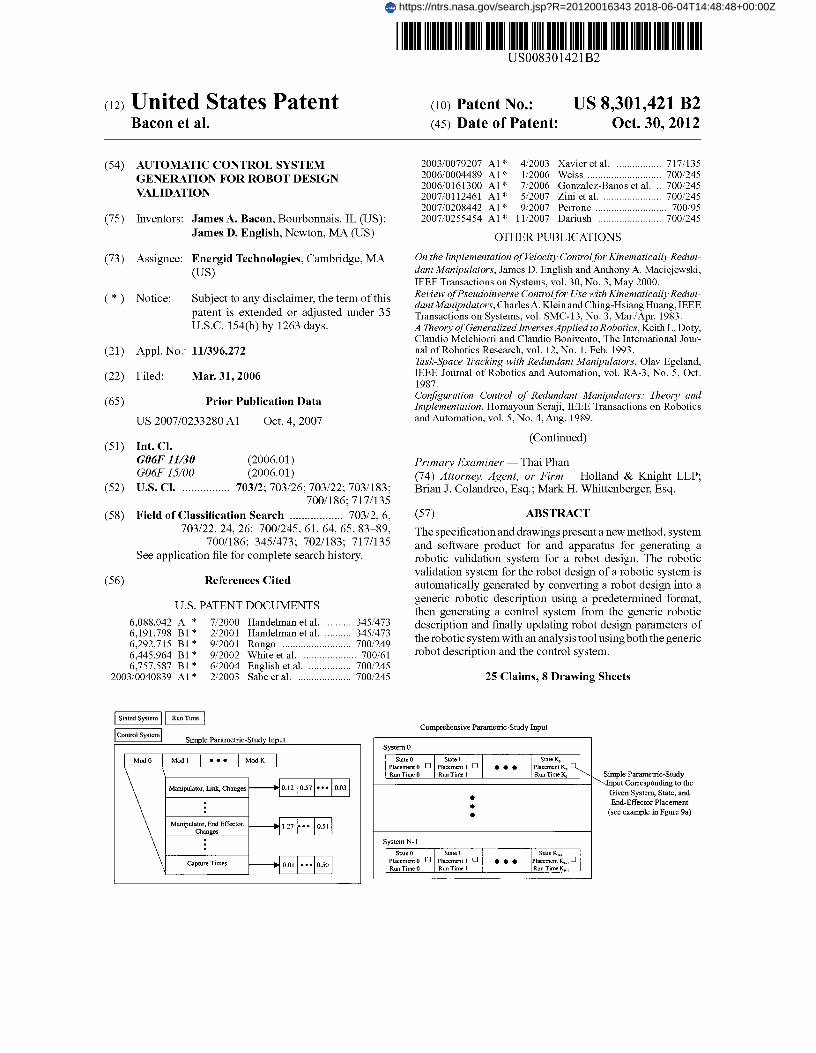
mu uuuu ui iiui imi um uui imi uiu mu uiii umi uu uii mi (12) United States Patent
Bacon et al.
(54) AUTOMATIC CONTROL SYSTEM GENERATION FOR ROBOT DESIGN VALIDATION
(75) Inventors: James A. Bacon, Bourbonnais, IL (US); James D. English, Newton, MA (US)
(73) Assignee: Energid Technologies, Cambridge, MA (US)
(*) Notice: Subject to any disclaimer, the term of this patent is extended or adjusted under 35 U.S.C. 154(b) by 1263 days.
(21) Appl. No.: 11/396,272
(22) Filed: Mar. 31, 2006
(65) Prior Publication Data
US 2007/0233280 Al Oct. 4, 2007
(51) Int. Cl.
G06F 11130 (2006.01)
G06F 15100 (2006.01) (52) U.S. Cl . ................ 703/2; 703/26; 703/22; 703/183;
700/186; 717/135 (58) Field of Classification Search .................. 703/2,6,
703/22, 24, 26; 700/245, 61, 64, 65, 83-89, 700/186; 345/473; 702/183; 717/135
See application file for complete search history.
(56) References Cited
U.S. PATENT DOCUMENTS
6,088,042 A * 7/2000 Handelman et al........... 345/473
6,191,798 BI* 2/2001 Handelman et al........... 345/473
6,292,715 BI* 9/2001 Rongo .......................... 700/249
6,445,964 BI* 9/2002 White et al . .................... 700/61
6,757,587 BI* 6/2004 English et al . ................ 700/245
2003/0040839 Al* 2/2003 Sabe et al . .................... 700/245
(1o) Patent No.: US 8,301,421 B2 (45) Date of Patent: Oct. 30, 2012
2003/0079207 Al* 4/2003 Xavier et al . ................. 717/135 2006/0004489 Al* 1/2006 Weiss ............................ 700/245 2006/0161300 Al* 7/2006 Gonzalez-Banos et al. .. 700/245 2007/0112461 Al* 5/2007 Zini et al ....................... 700/245 2007/0208442 Al* 9/2007 Perrone ........................... 700/95 2007/0255454 Al* 11/2007 Dariush ........................ 700/245
OTHER PUBLICATIONS
On the Implementation of Velocity Control for Kinematically Redun-dant Manipulators, James D. English and Anthony A. Maciejewski, IEEE Transactions on Systems, vol. 30, No. 3, May 2000. Review ofPseudoinverse Control for Use with Kinematically Redun-dantManipulators, Charles A. Klein and Ching-Hsiang Huang, IEEE Transactions on Systems, vol. SMC-13, No. 3, Mar./Apr. 1983. A Theory of Generalized Inverses Applied to Robotics, Keith L. Doty, Claudio Melchiorri and Claudio Bonivento, The International Jour-nal of Robotics Research, vol. 12, No. 1, Feb. 1993. Task-Space Tracking with Redundant Manipulators, Olav Egeland, IEEE Journal of Robotics and Automation, vol. RA-3, No. 5, Oct. 1987. Configuration Control of Redundant Manipulators: Theory and Implementation, Homayoun Seraji, IEEE Transactions on Robotics and Automation, vol. 5, No. 4, Aug. 1989.
(Continued)
Primary Examiner Thai Phan (74) Attorney, Agent, or Firm Holland & Knight LLP; Brian J. Colandreo, Esq.; Mark H. Whittenberger, Esq.
(57) ABSTRACT
The specification and drawings present a new method, system and software product for and apparatus for generating a robotic validation system for a robot design. The robotic validation system for the robot design of a robotic system is automatically generated by converting a robot design into a generic robotic description using a predetermined format, then generating a control system from the generic robotic description and finally updating robot design parameters of the robotic system with an analysis tool using both the generic robot description and the control system.
25 Claims, 8 Drawing Sheets
Stated System Run Time
control system Simple Parametric-Stud
Mod 0 Mod I • • • Mad K
Manipulator, Link, Changes
Manipulator, End Effector, Changes
Capture Times
Comprehensive Parametric-Study Input
System 0
State 0 Placement 0 Run Time 0
state I
Placement I Run Time I
• • • State K, Placemem K. Run Ti Z' Ko
• • •
System N-I
State 0 Placement 0 Rw Time 0
state I
Placement I Run Time I
• • • state Kam ,
Placement Kw , Run Time K
Simple Parametric-Study
Input Corresponding to the
Given System, State, and
End-Effector Placement
(see example in Fgure 9a)
https://ntrs.nasa.gov/search.jsp?R=20120016343 2018-06-04T14:48:48+00:00Z
US 8,301,421 B2 Page 2
OTHER PUBLICATIONS
Kinematic Programming Alternatives for Redundant Manipulators,
John Baillieul, IEEE, 1985. Improved Configuration Control for Redundant Robots, H. Seraj i and R. Colbaugh, Journal of Robotic Systems 7 (6), 897-928 (1990). Optimal Rate Allocation in Kinematically Redundant Manipula-tors—The Dual Projection Method, Ming. Z. Huang and Hareendra Varma, Proceedings ofthe 1991 IEEE, Intl. Conference on Robotics and Automation, Sacramento, California, Apr. 1991. Efficient Gradient Projection Optimization for Manipulators with Multiple Degrees of Redundancy, H. Zghal, R.V. Dubey and J. A. Enter, IEEE 1990. Numerical Integration and Digital-Model Updates in the AIM-9X Simulation, James D. English and James A. Bacon. Efficient Dynamic Computer Simulation ofRobotic Mechanisms, M. W. Walker and D. E. Orin, Journal of Dynamic Systems, Measure-ment, and Control, Sep. 1982, Vol. 104, pp. 205-211. An efficient Algorithm for Computation of Manipulator Inertia Matrix, Amir Fijany and Antal K. Bejczy, Journal of Robotic Sys-tems, 7(1), 57-80 (1990). Robot Dynamics Algorithms, Roy Featherstone, 1987. Robot Dymanics: Equations and Algorithms, Roy Featherstone and David Orin. Automatic Design and Manufacture of Robotic Lifeforms, Hod Lipson and Jordan B. Pollack, Nature, Vol. 406, Aug. 31, 2000, www.nature.com . Multicore, Dual-core, and the Future oflntel ars Technica, Monday, Sep. 13, 2004. Sony, Partners Offer Glimpse ofNew "Cell" Chip, Mark Hachman, Nov. 29, 2004, http://www.extremetech.com . NEC Develops Multicore Cell Phone Processor, by Marlyn Will-iams, Mar. 27, 2006, http://www.computerworld.com . A Simplex Method for Function Minimization, J. A. Nelder and R. Mead, p. 308-313. Downhill Simplex Method in Multidimensions, Numerical Recipes in C, The Art of Scientific Computing, William H. Press, Brian P. Flannery, Saul A. Teukolsky and William T. Vetterling, Chapter 10.4.
The]PNetworkAddress Translator, K. Egevang, P. Francis, Network Working Group, 1631, May 1994. STUN, Simple Traversal of User Datagram Protocol (UDP) Through NetworkAddress Translators (NATs), J. Rosenberg, J. Weinberger, et al, Network Working Group, 3489, Mar. 2003. Tea, a Tiny Encryption Algorithm, David J. Wheeler, Roger M. Needham, Cambridge University, England. Tea Extensions, Robert M. Needham and David J. Wheeler, Oct. 1996. Introduction to Robotics Mechanics and Control, John J. Craig, Chapter 2, p. 19-31. Modeling and Control ofElastic Joint Robots, M. W. Spong, Journal of Dynamic Systems, Measurement and Control, Dec. 1987. Vol. 109. Modeling and Identification of a Class of Servomechanism Systems With Stick-Slip Friction, Ka C. Cheok, Hongxing Hu, Nan K. Loh, Journal of Dynamic Systems, Measurement and Control Sep. 1988, Vol. 110. Animating Sand, Mud, and Snow, Robert W. Sumner, James F. O'Brien and Jessica K. Hodgins, Computer Graphics Forum, Vol. 18, (1999). Modeling Soil: Realtime Dynamic Models for Soil Slippage and Manipultaion, Xin Li and J. Michael Moshell, Institute for Simula-tion and Training, University of Central Florida. A Simulation System for Behaviour Evaluation of Off-Road Mobile Robots, C. Grand, F. Ben Amar and P. Bidaud, G. Andrade, Proceed-ings of the CLAWAR 2001 conference. VrtualActuator Control, Jerry Pratt, Ann Torres, Peter Dilworth, Gill Pratt, IEEE 1996. Legged Robots That Balance, Marc H. Raibert, Chapter 1, p. 1-27. Accelerating the Design Cycle in a Converging World, Mihir Ravel, ED Online ID #1767, Feb. 2, 2004. Brett et al. "Free-Climbing with a Multi-Use Robot," Proceedings of the International Symposium on Experimental Robotics (ISER), Singapore, Jun. 2004, pp. 1-10. Doty et al. "Robot manipulability" IEEE Transactions on Robotics and Automation, Jun. 1995, Machine Intelligence Lab., Florida Univ., Gainesville, FL, Vol. 11, Issue 3, pp. 462-468.
* cited by examiner
/ 36
/ 38
Convert generic robotic description to native format of the analysis tool by analysis software interpreter (optional)
Generate updated robot design parameters (i.e., generate results) with analysis tool using the generic robot description and the control system
Write results to XML format or to post processing tools (e.g., in native format) and then update the robot design
/ 40
U.S. Patent Oct. 30, 2012 Sheet 1 of 8
US 8,301,421 B2
10
12
Design tool
(e.g., CAD)
14
Design software
interpreter
16
Analysis software
interpreter (optional)
18
Analysis tool
(software)
Post- processing
20 tool
Figure 1
Read a file describing robot design in its proprietary format by the robot 30
design tool (e.g., CAD)
32 Convert the file describing the robot design into a generic robotic
description (e.g., XML) by design software interpreter
34 Generate a control system from the generic robotic description for
controlling the robot by design software interpreter
Figure 2
C6
U.S. Patent Oct. 30, 2012 Sheet 2 of 8
US 8,301,421 B2
CL Ob
N N
G O
P O z
Co
N
Co u-
a~
U
Z 4
Y N
Cu O T-
V- i
N V-
Map of Surface Properties
Entire Basic Shapes
String-Float Map
°red' 0.5 'green' 0.5 "blue' 0.75 'alpha" 0.65 'shininess' 10.0
'Metal- 1 .
siring-string map string-float map
"
string-integer map
U.S. Patent Oct. 30, 2012 Sheet 3 of 8
US 8,301,421 B2
Compound Shape
Shape 0 +
Shape 1 Shape 2 Figure 4a
~u Basic Shapes
Polyhedron Sphere Capsule
Lozenge
(D I:T ZD Ellipsoid Box Tetrahedron
Half Space
Figure 4b
Each Polygon in a Polyhedron
Figure 4c
U.S. Patent Oct. 30, 2012 Sheet 4 of 8 US 8,301,421 B2
Link Distal kinematics Link kinematics frame (joins with
children)
,.~ Primary frame (used to specify
Proximal kinematics physical extent, mass properties,
; and end effectors) frame (joins with , parent) A shape representing the physical
extent of the link.
Figure 5
Link 0 Link 1 Base Link (moves relative to (moves relative to
(fixed or mobile) Base Link) Link 0)
Link 2 (moves relative to
Link 1)
• • Link 3
(moves relative to Link 1)
Figure 6
U.S. Patent Oct. 30, 2012 Sheet 5 of 8 US 8,301,421 B2
Stated System
State
Velocity State Group
0 Base Joints
Group Base❑ Joints®
Position State Group 0
Base❑ Joints
Group N Base❑ Joints
Morphing State Group
0 Substitute Link Map
Group N Substitute Link Map
System
Reference Information Applicable to all Environmental Components
Physical Components
Link Tree I Link Data:
Group Kinematics 0 Link Mass Properties
Indexing Physical Extent
❑
Surface Properties Volume Properties
Link Tree Link Data:
Group Kinematics
N Link Mass Properties
Indexing Physical Extent
❑
Surface Properties Volume Properties
Figure 7
U.S. Patent Oct. 30, 2012 Sheet 6 of 8 US 8,301,421 B2
Stated System Run Time
rnntml Svctem Simnle Parametric-Studv Input
Mod 0 Mod 1 1 • • • 1 Mod K
1.27 • • • 0.51
0.01 • • • 0.50
Figure 8a
Comprehensive Parametric-Study Input
Manipulator, Link, Changes
Manipulator, End Effector, Changes
Capture Times
0.12 0.57 • • • 0.03
Parametric-Study Corresponding to the sn System, State, and -Effector Placement example in Fgure 9a)
Figure 8b
U.S. Patent Oct. 30, 2012 Sheet 7 of 8 US 8,301,421 B2
Routing Node
Client Nodes El FO-1 FEII 000 EIEI
Figure 9
WAN (Internet)
Firewall and NAT devices
LAN
WAN Routing Node
LAN Routing Node
Client Node
Figure 10
U.S. Patent Oct. 30, 2012
Sheet 8 of 8
US 8,301,421 B2
Robot
Ground
Rock 1 Rock 2
;)~o 0 0 0
• •
Manipulator 0 Manipulator 1
Manipulator 2 Manipulator 3
Figure 11 a
Radius of Node
Influence Depth
Node Distance
Radius of Influence Method
Figure 11 b
US 8,301,421 B2 1
AUTOMATIC CONTROL SYSTEM GENERATION FOR ROBOT DESIGN
VALIDATION
STATEMENT REGARDING FEDERALLY SPONSORED RESEARCH AND DEVELOPMENT
The invention was supported by NASA under contracts NNC05CA77C and NNC06CA27C. The U.S. Government has certain rights in the invention.
FIELD OF THE INVENTION
The invention generally relates to robotics and more spe-cifically to generating a robotic validation system for a robot design.
BACKGROUND ART
Many good CAD (computer-aided design) software pack-ages support design, such as SOLID WORKS, UG NX, and PRO/ENGINEER. Also many good packages provide analy-sis, such as WORKSPACES, DARVIM2K, and ADAMS. Yet design and analysis packages rarely work together well to meet the specific needs of robot designers. For maximum efficiency, a robot designer might want to modify a hardware design and test it in software 10-20 times in a workday. Yet modifying a robot design on one software package, then converting and validating it on another can take days of effort, and when finished, the designer may not have access to the information really needed for robot analysis, such as control torques and sensor data. This inefficiency is expensive and time consuming, and it is detrimental to the quality of robot designs.
New ways for connecting the existing well-solved pieces of the robot design cycle as well as new robot-specific analy-sis are needed. Constructing a part in a CAD program is largely solved. Simulating rigid-body dynamics with differ-ential equations is largely solved. A challenge lies in connect-ing these and other components and integrating human input in an efficient way.
Another challenge lies in adding all the capability needed by roboticists. Most commercial packages are not tailored to robotics. To make a complete product that will find wide acceptance and use, new algorithms and software should support robotic workspace, control, manipulation, sensor, actuator, and locomotion analysis. The human interface should provide robotics-tailored data, describedusing robotic terminology. A new software framework that integrates com-mercial capability where available and adds new capability where needed may change the nature of development for the entire robotics field.
DISCLOSURE OF THE INVENTION
According to a first aspect of the invention, a method for generating a validation system to validate a robot design of a robotic system, comprises the steps of: automatically con-verting a robot design into a generic robotic description using a predetermined format; automatically generating a control system from the generic robotic description; and updating robot design parameters of the robotic system with an analy-sis tool using the generic robot description and the control system.
According further to the first aspect of the invention, the updating of robot design parameters may be automatic.
2 Further according to the first aspect of the invention, the
robot design may be loaded from robot design software. Still further according to the first aspect of the invention,
the robot design may comprise at least one of: a) a hardware 5 design, b) an electronic design, and b) surface properties.
According further to the first aspect of the invention, the analysis tool may provide a simulation and the simulation may be at least one of: a) a kinematic simulation, b) a dynamic simulation, c) a terrain simulation.
i0 According still further to the first aspect of the invention, the predetermined format may be at least one of: a) an exten-sible markup language (XML), and b) a text based format.
According further still to the first aspect of the invention,
15 the robotic description may comprise at least one of: a) a model of the environment, and b) sensor models.
According yet further still to the first aspect of the inven-tion, the control system may comprise at least one of: a) a kinematic component, b) a dynamic component, c) an adap-
20 tation feature for avoiding self-collisions and collisions with the environment, and d) an adaptation feature to control deforming links and avoid collisions with the deforming links.
Yet still further according to the first aspect of the inven- 25 tion, the robotic system may comprise at least one feature out
of: a) one or more articulated manipulators with one or more rigid or deforming links having a fixed base, b) one or more articulated mobile mechanisms with one or more rigid or deforming links, c) a bifurcating kinematic structure, and d) a
30 closed kinematic structure. Still yet further according to the first aspect of the inven-
tion, the generating the robotic validation may be provided using at least one of: a) network communications, and b) network communications over Internet.
35 Still further still according to the first aspect of the inven- tion, the robotic system may be controlled using at least one of: a) network communications; and b) network communica-tions over Internet.
According further still to the first aspect of the invention, 40 the control system may be established using at least one of: a)
network communications; and b) network communications over Internet.
According yet further still to the first aspect of the inven-tion, the robotic system may be used for at least one applica-
45 tion out of: a) space applications, b) military applications, c) agricultural applications, d) medical applications, e) domes-tic applications, f) mining applications, and g) agricultural applications.
According still yet further still to the first aspect of the 50 invention, the updating robot design parameters may com-
prise calculating updated robotic parameters by the analysis tool using at least one of: a) Monte Carlo analysis, b) para-metric analysis, and c) parameter-optimization analysis. Fur-ther, the updating robot design parameters may comprise
55 using automatically the updated robotic parameters calcu-lated by the analysis tool to improve the design of the robotic system by the design tool. Still further, the updated robotic parameters may be provided to a design tool for improving the design of the robotic system by the design tool.
60 Yet still further according to the first aspect of the inven-tion, the general robotic description may comprise at least one of the following features: a) shapes, b) links, c) manipulators, d) stated systems, e) mechanisms with generic joint articula-tion comprising sliding, rotational, elliptical, or spherical
65 articulations, and f) automatic simplification of the hardware design comprising physical dimensions, surface properties, kinematics properties or dynamics properties.
US 8,301,421 B2 3
Still yet further according to the first aspect of the inven-tion, the control system may use Jacobian -based algorithm. Further, the control system may use a velocity control frame-work using the following algorithm:
v=J(q)q*, (1),
wherein V is an m-length vector representing a motion of end effectors ; q is a vector of joint positions , q* is an n-length vector formed by augmenting a derivative vector q with linear and angular velocities of a base link of the robotic system; and J is an mxn Jacobian as a function of q, wherein
i, - ~ NTW J 1
~ ~ - NV
JT FI
wherein Njis an nx (n—m) set of vectors that spans a null space of J, a is a scalar , W(q) is a matrix function , and F(q) is a vector function.
According to a second aspect of the invention , a computer program product comprising : a computer readable storage structure embodying computer program code thereon for execution by a computer processor with the computer pro-gram code, characterized in that it includes instructions for performing the steps of the first aspect of the invention, indi-cated as being performed by any component of the validation system.
According to a third aspect of the invention, a robotic validation system for a robot design of a robotic system performed automatically , comprises: a design software inter-preter, for converting the robot design into a generic robotic description using a predetermined format , and for generating a control system from the generic robotic description; and an analysis tool, for updating robot design parameters of the robotic system using the generic robot description and the control system.
According further to the third aspect of the invention, the design software interpreter maybe a client node of a network.
Further according to the third aspect of the invention, the robotic validation system may comprise an analysis software interpreter , for converting the generic robotic description to a native format of the analysis tool. Further, the analysis soft-ware interpreter may be a client node of a network.
Still further according to the third aspect of the invention, the robotic validation system may comprise a design tool, for reading a file describing the robot design in a native format for converting the robot design to the generic robotic description using the predetermined format. Further, the robotic valida-tion system may comprise a Post-processing tool, for writing results of the updating robot design parameters to improve the design of the robotic system by the design tool.
BRIEF DESCRIPTION OF THE DRAWINGS
For a better understanding of the nature and objects of the present invention, reference is made to the following detailed description taken in conjunction with the following drawings, in which:
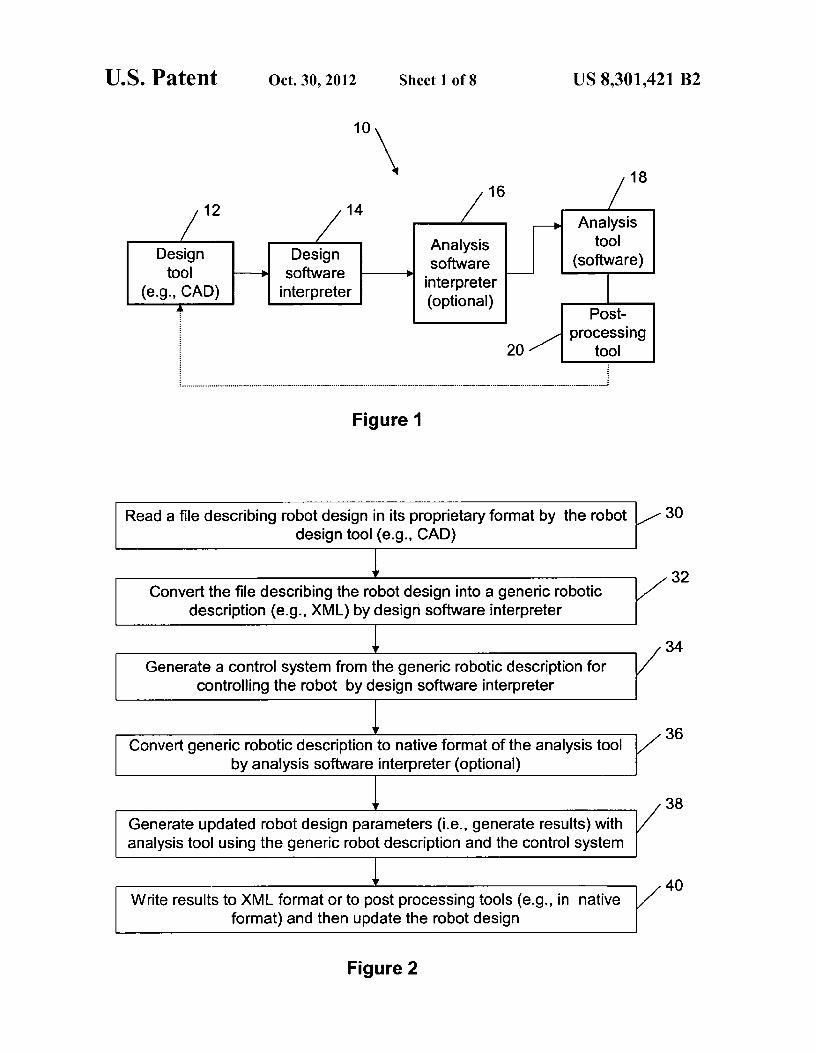
FIG.1 is a block diagram of a robotic validation system for a robot design , according to an embodiment of the present invention;
FIG. 2 is a flow chart of a robotic validation system for a robot design , according to an embodiment of the present invention;
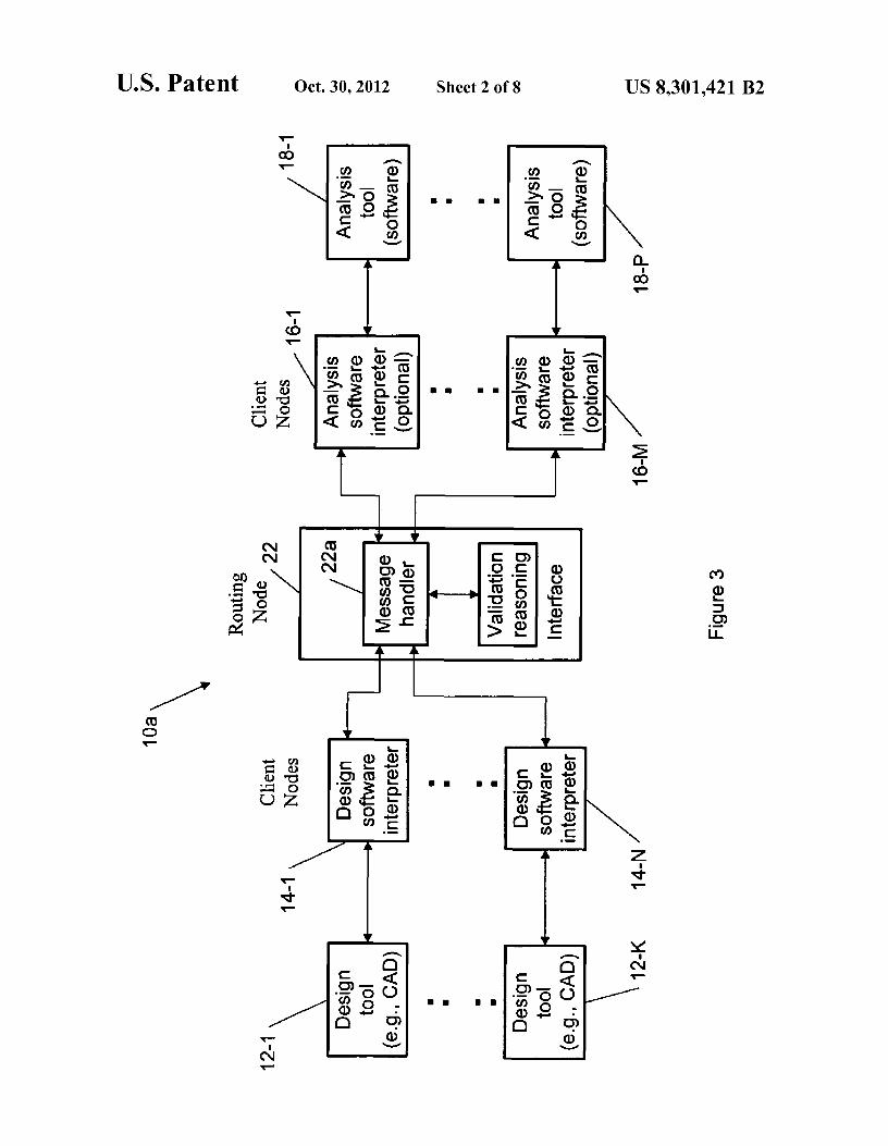
4 FIG. 3 is a block diagram of a robotic validation system for
a robot design for multiple client nodes using network con-nections , according to an embodiment of the present inven-tion;
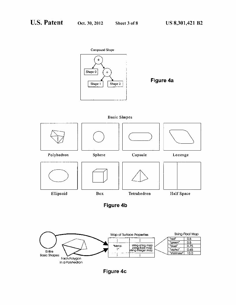
5 FIG. 4a is a block diagram representing a tree structure for robot link's physical extent, according to an embodiment of the present invention;
FIG. 4b are pictures of basic shapes which can be applied, according to embodiments of the present invention;
10 FIG. 4c is a schematic representation of a string-to-surface-property map, according to an embodiment of the present invention;
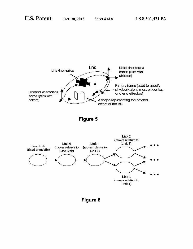
FIG. 5 is a schematic representation of a link for construct-ing a robotic description , according to an embodiment of the
15 present invention; FIG. 6 is a schematic representation of a manipulator con-
structed by connecting links in a tree structure , according to an embodiment of the present invention;
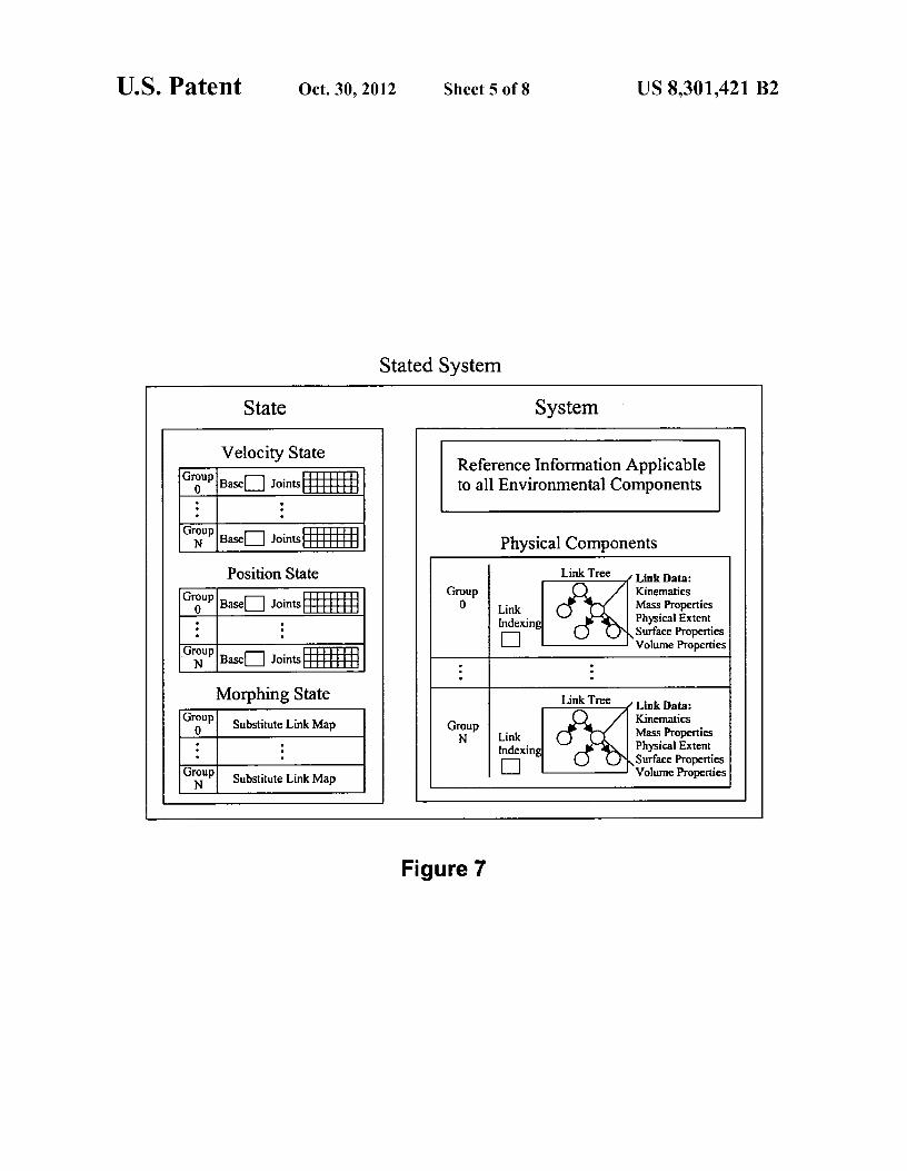
FIG. 7 is a schematic representation of a stated system as a 20 combination of a state and a system, according to an embodi-
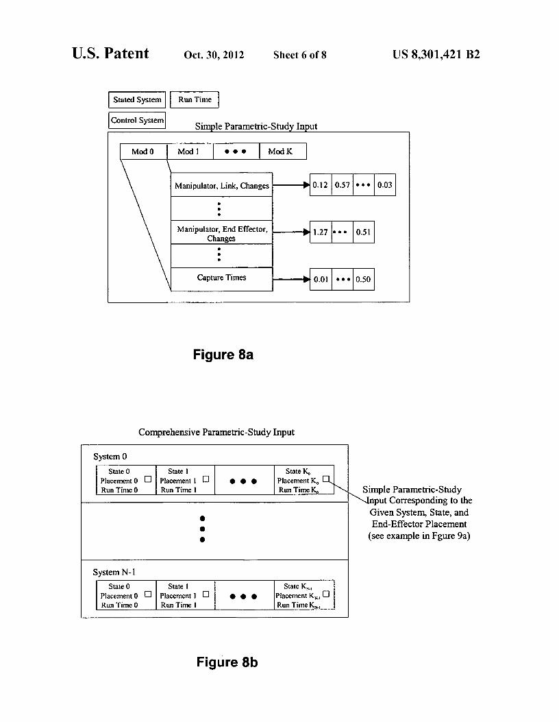
ment of the present invention; FIG. 8a is a simple form of input to the parametric study
which utilizes a reference stated system , control system and run time, according to an embodiment of the present inven-
25 tion;
FIG. 8b is a comprehensive form of input to the parametric study which uses any number of system changes combined with any number of state, placement and run-time changes, according to an embodiment of the present invention;
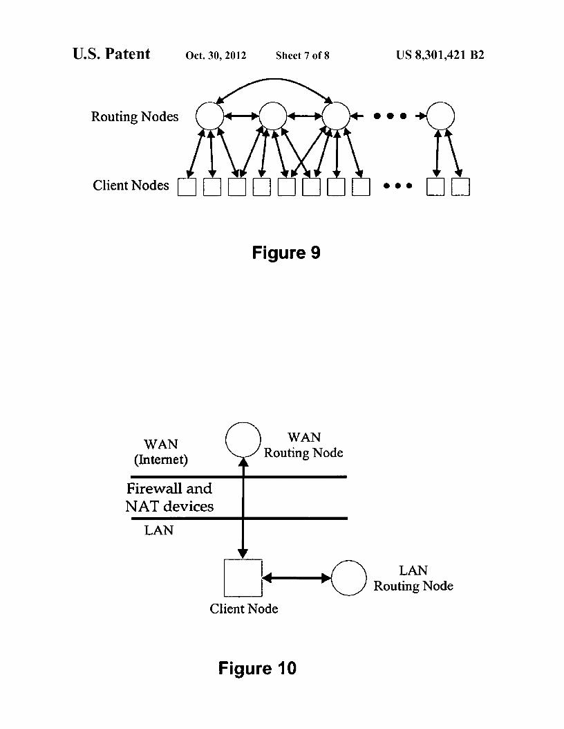
30 FIG. 9 is a schematic diagram of an architecture supporting peer-to-peer organization for the network implementation of embodiments of the present invention;
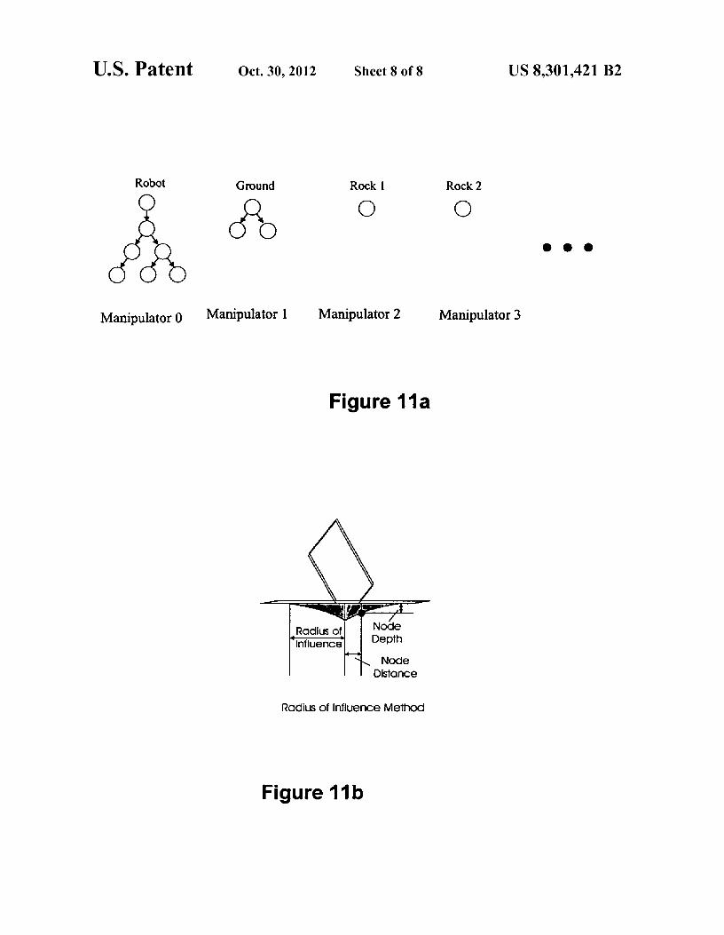
FIG. 10 is a schematic representation of a network imple-mentation , wherein each client maintains both primary LAN
35 routing node and a primary WAN routing node, according to an embodiment of the present invention;
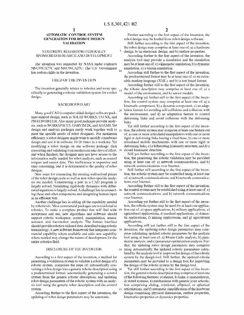
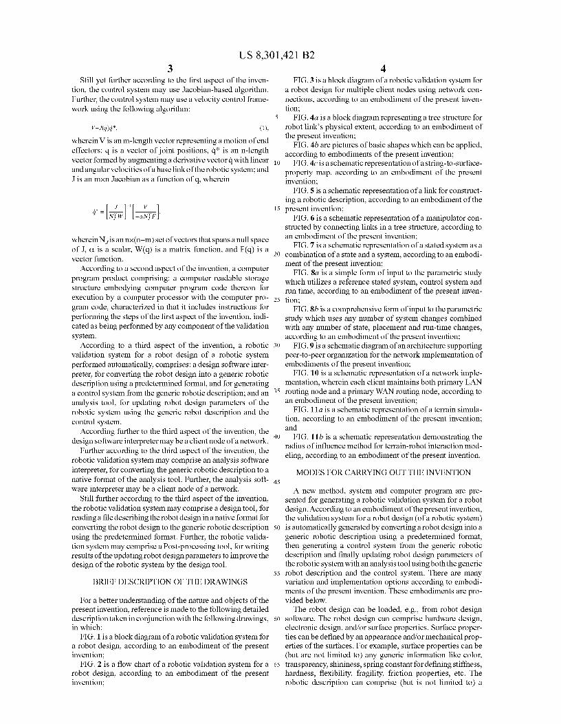
FIG. 11a is a schematic representation of a terrain simula-tion , according to an embodiment of the present invention; and
40 FIG. 11b is a schematic representation demonstrating the radius of influence method for terrain-robot interaction mod- eling, according to an embodiment of the present invention.
MODES FOR CARRYING OUT THE INVENTION 45
A new method, system and computer program are pre-sented for generating a robotic validation system for a robot design. According to an embodiment of the present invention, the validation system for a robot design (of a robotic system)
50 is automatically generated by converting a robot design into a generic robotic description using a predetermined format, then generating a control system from the generic robotic description and finally updating robot design parameters of the robotic system with an analysis tool using both the generic
55 robot description and the control system. There are many variation and implementation options according to embodi-ments of the present invention . These embodiments are pro-vided below.
The robot design can be loaded, e.g., from robot design 60 software. The robot design can comprise hardware design,
electronic design , and/or surface properties . Surface proper- ties can be defined by an appearance and/or mechanical prop- erties of the surfaces . For example, surface properties can be (but are not limited to) any generic information like color,
65 transparency , shininess , spring constant for defining stiffness, hardness, flexibility, fragility, friction properties, etc. The robotic description can comprise (but is not limited to) a
US 8,301,421 B2 5
6
model of the environment and/or sensor models (e.g., for sible markup language (XML). Typically, the design software
providing a force feedback to assist with grasping objects), interpreter 14 is plugged into the CAD software at load time
such as touch sensors, force sensors, joint encoders, acceler- (e.g., component object model (COM) or dynamic link
ometers, gyroscopic sensors, color cameras, gray-level cam- library (DLL) linking can be used to accomplish this integra- eras, ladar, or hyperspectral sensors. 5 tion). Because it is plugged in at run-time, the interpreter 14
The robotic system can be used (but is not limited to): space can use the calling methods of the design tool 12 (e.g., the
applications, military applications, agricultural applications, CAD software) to get the hardware design. Along with the
domestic applications, mining applications, medical applica- specific robotic description (e.g., an XML file with a conver-
tions, etc. The robotic system can comprise the following sion of the CAD hardware design), a new control system features: io (also, e.g., in the XML) for controlling the robot and appro-
a) one or more articulated manipulators with one or more priate for the robot design is created by the interpreter 14. The
rigid (in general, links can be perfectly rigid, i.e., no user can also specify the type of analysis/simulation (e.g., the
bending, growing, shrinking, etc.) or deforming links parameter optimization, Monte Carlo simulation, parameter
(deforming links, designed to change shape in a control- optimization study, kinematic simulation, dynamic simula- lable way, are not rigid bodies and typically have more 15 tion, and/or dynamic simulation, etc.) to be performed, typi-
degrees of freedom than rigid bodies, e.g., more than 6
cally after being prompted by the interpreter 14.
degrees of freedom;) having a fixed base (fixed based
Moreover, if the analysis tool 18 cannot read the predeter-
robots are often seen in manufacturing wherein, e.g., an minedformat (e.g., XML) directly, an analysis software inter-
arm is attached to a fixed base which cannot move, preter 16 converts the generic robotic description (e.g., in whereas mobile robots may be on mobile platforms 20 XML) to its native format. The analysis tool 18 then performs often on wheels, legs, or tracks); the analysis specified by the user with the results being fed
b) one or more articulated mobile mechanisms with one or
back to the design tool 12 (e.g., using the interpreter 14). more rigid or deforming links, and/or
Alternatively, the analysis tool 18 can write out results to the
c) a bifurcating kinematic structure. native format of a post-processing tool 20. Then the post- The general robotic description can comprise (but is not 25 processing tool 20 writes results in the XML which can be
limited to) the following features: shapes, links, manipula- read by the design software interpreter 14 subsequently
tors, stated systems, mechanisms with generic joint articula- updating the CAD model of the robot design by using the
tion comprising sliding, rotational, elliptical, or spherical
calling methods of the design tool 12.
articulations, and/or automatic simplification of the hardware
FIG. 2 is a flow chart of a robotic validation system 10 for design comprising physical dimensions, surface properties, so a robot design, according to an embodiment of the present kinematics properties or dynamics properties. invention. The flow chart of FIG. 2 only represents one pos-
The control system can be automatically generated from sible scenario among others. In a method according to the first
the robotic description. The control system can comprise (but embodiment of the present invention, in a first step 30, the
may not be limited to): a kinematic component, a dynamic robot design tool (e.g., CAD) 12 reads the file describing the component, an adaptation feature for avoiding self-collisions 35 robot design of the robotic system in its proprietary format. In
and collisions with the environment, and an adaptation fea- a next step 32, the design software interpreter 14 converts the
ture to control deforming links and provide collision avoid- file describing the robot design into a generic robotic descrip- ance with deforming links. tion (e.g., XML). In a next step 34, subsequently, the design
The predetermined format may be generally text based and software interpreter 14 also generates a control system from can use, e.g., an extensible markup language (XML). The 40 the generic robotic description for controlling the robot (e.g., network communications (e.g., over Internet) can be used for also in XML).
generating the robotic validation, for controlling the robotic
Moreover, in a next step 36, the analysis software inter- system, and/or for establishing the control system. preter 16, if necessary, converts the generic robotic descrip-
The analysis tool can provide a simulation which can (but
tion to a native format of the analysis tool 18. In a next step 38, is not limited to) kinematic simulation, dynamic simulation, 45 the analysis tool 18 generates updated robot design param-
and/or terrain simulation. The updating of robot design eters (i.e., generates results) using the generic robot descrip-
parameters can comprise calculating updated robotic param- tion and the control system provided by the design software
eters by the analysis tool using (but not be limited to) the
interpreter 14. Finally, in a next step 40, results generated by
following methods: Monte Carlo analysis, parametric analy- analysis tool 18 are written to the XML format or to a post sis, and/or parameter optimization control. The updating of 50 processing tool (e.g., in the native format) subsequently
robot design parameters can comprise using automatically updating the CAD model of the robot design by the design
the updated robotic parameters calculated by the analysis tool
tool 12.
to improve the design of the robotic system by the design tool. FIG. 3 shows an example among others of a robotic vali-
The updated robotic parameters can be provided to a design
dation system 10a for a robot design for multiple client nodes tool for improving the design of the robotic system by the 55 using network connections, according to an embodiment of design tool. the present invention. The robotic validation system 10a (or
FIG.1 is an example among others of a block diagram of a the design-and-validation system) is organized using client
simplified robotic validation system 10 for a robot design, and routing nodes that exchange information on robot design
according to an embodiment of the present invention. The and analysis results over networked or direct connections. example of FIG.1 canbe implemented, e.g., on one computer. 6o There are two possible groups of client nodes. One group can
The design tool 12 can be CAD software represented, e.g., in comprise N design software interpreters 14-1, 14-2, ... ,
SOLID WORKS. The CAD software (the block 12) reads a
14-N. Each of these interpreters 14-1, 14 -2, ... , 14-N has file describing a robot design in its proprietary format. similar functionality as the block 14 of FIG. 1. Another (op-
In response to an appropriate command from the user, the tional) node group can comprise M analysis software inter- design software interpreter 14 converts the file describing a 65 preters 16-1,16-2, ... ,16-M. Each of these interpreters 16-1,
robot design (e.g., a CAD hardware design) into a specific
16-2, ... , 16-M has similar functionality as the block 16 in
robotic description using a predetermined format, e.g., exten- FIG. 1. The routing node (interface) 22 has a message handler
US 8,301,421 B2 7
22a which provides a network communication (e.g., through the Internet) between any of the client nodes 14-1, 14 -2, .. . 14 -N and any of the client nodes 16-1, 16-2, ... , 16-M. The validation reasoning block may represent software that ensures the validity of all exchanged messages, using, e.g., an XML schema. The system 10a can have K design tools 12-1, 12 -2, ... ,12-K (e.g., installed on K network computers) and P analysis tools 18-1, 18 -2, ... , 18 -P (e.g., installed on P network computers), wherein each of these blocks has the same functionally as blocks 12 and 18, respectively, in FIG. 1. Each of the K design tools 12-1, 12 -2, ... , 12 -K can use services of any or pre-selected design software interpreters from the N design software interpreters 14-1,14 -2, ... ,14 -N for translating to/from the predetermined format (e.g., XML). Similarly, each of the P analysis tools 18-1, 18-2, ... , 18 -K can use services of any or pre-selected design software inter-preters from the M analysis software interpreters 16-1, 16-2, ... , 16-N for translating to/from the predetermined format (e.g., XML). It is noted that K, N, M and P are integers, which can have different values or a combination thereof can have the same values.
Direct interfaces to design and validation software is made through client nodes, and connections between design and validation software is made through routing nodes. When the nodes are parts of a single application, the communication will typically be through a direct exchange of information in memory. However, when the nodes are parts of the network, the communication will be, e.g., through the XML over TCP/ IP (transport control protocol/internet protocol) as illustrated in FIG. 3.
The performance of the system 10a is similar to the per-formance of a simple system shown in FIG. 1. For example, the design software interpreter 14-1 takes the hardware design as contained in the CAD design software (i.e., the design tool 12-1) and converts it to the generic robotic description with a control system. The user can also specify the form of analysis to apply to the conversion (e.g., Monte Carlo simulation or other methods according to embodiments of the present invention). The routing node 22 automatically sends the data in the form of, e.g., XML to the computer with the analysis tool 18-1. If needed, the analysis software inter-preter 16-1 converts the XML to the format required by the analysis tool 18-1. The analysis tool 18-1 performs the simu-lation and sends results back to the CAD design software for updating the CAD model of the robot design by the design tool 12-1.
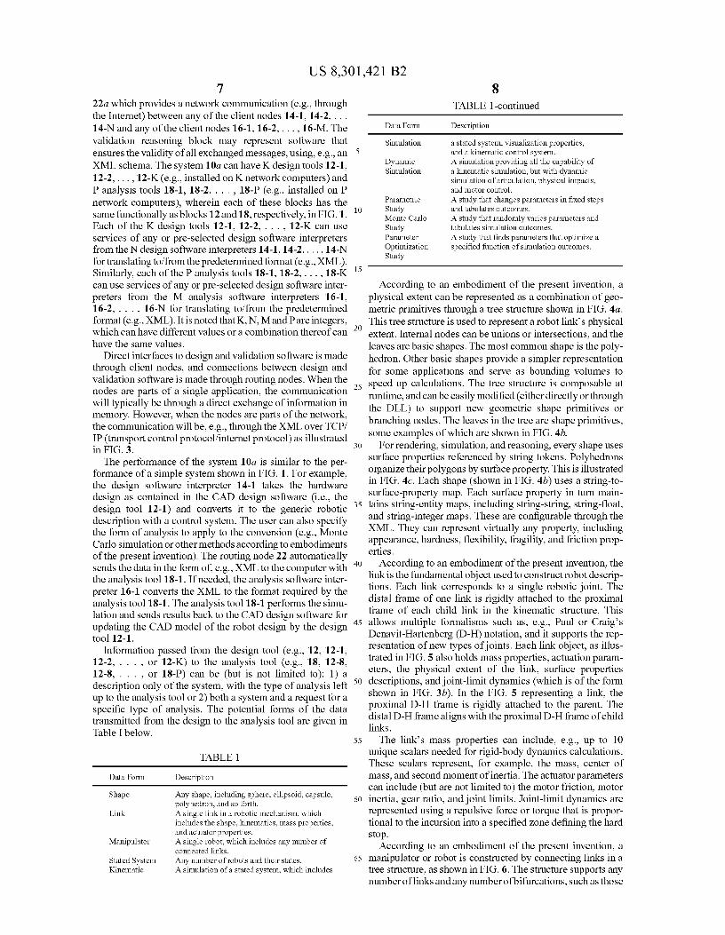
Information passed from the design tool (e.g., 12, 12-1, 12 -2, .. or 12-K) to the analysis tool (e.g., 18, 12-8, 12-8, .. or 18-P) can be (but is not limited to): 1) a description only of the system, with the type of analysis left up to the analysis tool or 2) both a system and a request for a specific type of analysis. The potential forms of the data transmitted from the design to the analysis tool are given in Table I below.
TABLE 1
8 TABLE 1-continued
Data Form Description
Simulation a stated system, visualization properties, 5 and a kinematic control system.
Dynamic A simulation providing all the capability of Simulation a kinematic simulation, but with dynamic
simulation of articulation, physical impacts, and motor control.
Parametric A study that changes parameters in fixed steps
10 Study and tabulates outcomes. Monte Carlo A study that randomly varies parameters and Study tabulates simulation outcomes. Parameter A study that finds parameters that optimize a Optimization specified function of simulation outcomes. Study
15
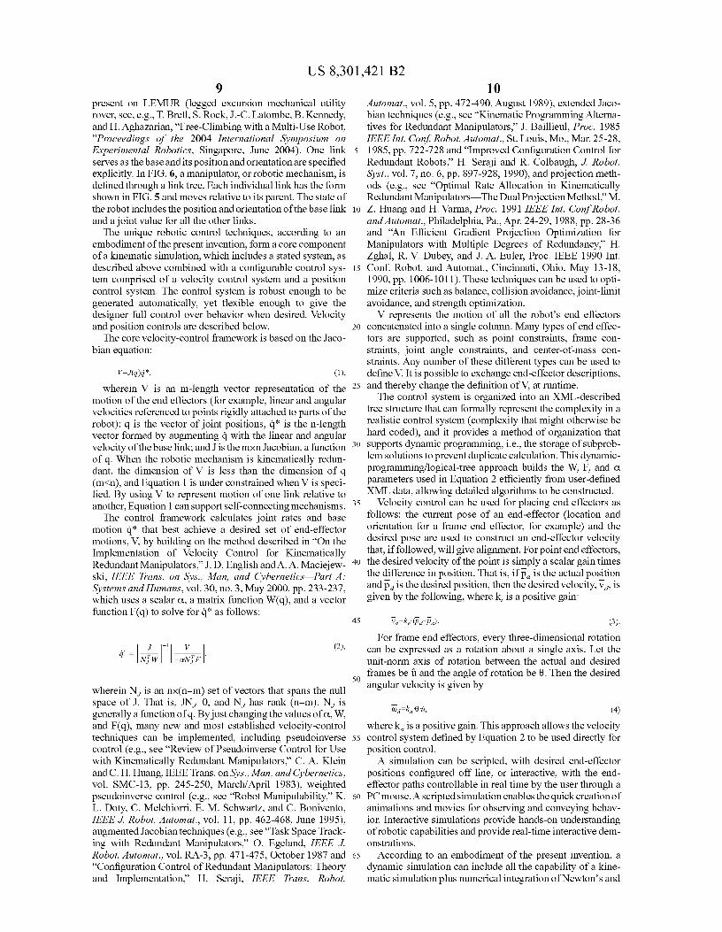
According to an embodiment of the present invention, a physical extent can be represented as a combination of geo-metric primitives through a tree structure shown in FIG. 4a.
20 This tree structure is used to represent a robot link's physical extent. Internal nodes can be unions or intersections, and the leaves are basic shapes. The most common shape is the poly-hedron. Other basic shapes provide a simpler representation for some applications and serve as bounding volumes to
25 speed up calculations. The tree structure is composable at runtime, and can be easily modified (either directly or through the DLL) to support new geometric shape primitives or branching nodes. The leaves in the tree are shape primitives, some examples of which are shown in FIG. 4b.
30 For rendering, simulation, and reasoning, every shape uses surface properties referenced by string tokens. Polyhedrons organize their polygons by surface property. This is illustrated in FIG. 4c. Each shape (shown in FIG. 4b) uses a string-to-surface-property map. Each surface property in turn main-
35 tains string-entity maps, including string-string, string-float, and string-integer maps. These are configurable through the XML. They can represent virtually any property, including appearance, hardness, flexibility, fragility, and friction prop-erties.
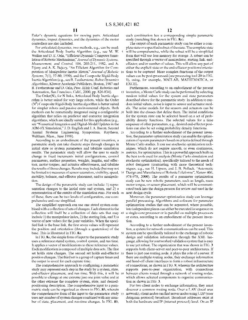
40 According to an embodiment of the present invention, the link is the fundamental object used to constructrobot descrip-tions. Each link corresponds to a single robotic joint. The distal frame of one link is rigidly attached to the proximal frame of each child link in the kinematic structure. This
45 allows multiple formalisms such as, e.g., Paul or Craig's Denavit-Hartenberg (D-H) notation, and it supports the rep-resentation of new types of joints. Each link object, as illus-trated in FIG. 5 also holds mass properties, actuation param-eters, the physical extent of the link, surface properties
5o descriptions, and joint-limit dynamics (which is of the form shown in FIG. 3b). In the FIG. 5 representing a link, the proximal D-H frame is rigidly attached to the parent. The distal D-H frame aligns with the proximal D-H frame of child links.
55 The link's mass properties can include, e.g., up to 10 unique scalars needed for rigid-body dynamics calculations. These scalars represent, for example, the mass, center of mass, and second moment of inertia. The actuator parameters can include (but are not limited to) the motor friction, motor
60 inertia, gear ratio, and joint limits. Joint-limit dynamics are represented using a repulsive force or torque that is propor-tional to the incursion into a specified zone defining the hard stop.
According to an embodiment of the present invention, a 65 manipulator or robot is constructed by connecting links in a
tree structure, as shown in FIG. 6. The structure supports any number of links and any number of bifurcations, such as those
Data Form Description
Shape Any shape, including sphere, ellipsoid, capsule, polyhedron, and so forth.
Link A single link in a robotic mechanism, which includes the shape, kinematics, mass properties, and actuator properties.
Manipulator A single robot, which includes any number of connected links.
Stated System Any number of robots and their states. Kinematic A simulation of a stated system, which includes
US 8,301,421 B2 9
10 present on LEMUR (legged excursion mechanical utility rover, see, e.g., T. Bretl, S. Rock, J.-C. Latombe, B. Kennedy, and H. Aghazarian, "Free-Climbing with a Multi-Use Robot, "Proceedings of the 2004 International Symposium on Experimental Robotics, Singapore, June 2004). One link serves as the base and its position and orientation are specified explicitly. In FIG. 6, a manipulator, or robotic mechanism, is defined through a link tree. Each individual link has the form shown in FIG. 5 and moves relative to its parent. The state of the robot includes the position and orientation of the base link and a joint value for all the other links.
The unique robotic control techniques, according to an embodiment of the present invention, form a core component of a kinematic simulation, which includes a stated system, as described above combined with a configurable control sys-tem comprised of a velocity control system and a position control system. The control system is robust enough to be generated automatically, yet flexible enough to give the designer full control over behavior when desired. Velocity and position controls are described below.
The core velocity-control framework is based on the Jaco-bian equation:
v=J(q)q*, (1),
wherein V is an m-length vector representation of the motion of the end effectors (for example, linear and angular velocities referenced to points rigidly attached to parts of the robot); q is the vector of joint positions, q* is the n-length vector formed by augmenting q with the linear and angular velocity of the base link; and J is the mxn Jacobian, a function of q. When the robotic mechanism is kinematically redun-dant, the dimension of V is less than the dimension of q (m<n), and Equation 1 is under constrained when V is speci-fied. By using V to represent motion of one link relative to another, Equation 1 can support self-connecting mechanisms.
The control framework calculates joint rates and base motion q* that best achieve a desired set of end-effector motions, V, by building on the method described in "On the Implementation of Velocity Control for Kinematically Redundant Manipulators," J. D. English andA. A. Maciejew-ski, IEEE Trans. on Sys., Man, and Cybernetics Part A: Systems andIlumans, vol. 30, no. 3, May 2000, pp. 233-237, which uses a scalar a, a matrix function W(q), and a vector function F(q) to solve for q* as follows:
q - kVT W1 ~ -.N,,F]
wherein Nj is an nx(n—m) set of vectors that spans the null space of J. That is, JNj 0, and Nj has rank (n—m). Nj is generally a function of q. By just changing the values of a, W, and F(q), many new and most established velocity-control techniques can be implemented, including pseudoinverse control (e.g., see "Review of Pseudoinverse Control for Use with Kinematically Redundant Manipulators," C. A. Klein and C. H. Huang, IEEE Trans. on Sys., Man, and Cybernetics, vol. SMC-13, pp. 245-250, March/April 1983), weighted pseudoinverse control (e.g., see "Robot Manipulability," K. L. Doty, C. Melchiorri, E. M. Schwartz, and C. Bonivento, IEEE J. Robot. Automat., vol. 11, pp. 462-468, June 1995), augmented Jacobian techniques (e.g., see "Task Space Track-ing with Redundant Manipulators," O. Egeland, IEEE J. Robot. Automat., vol. RA-3, pp. 471-475, October 1987 and "Configuration Control of Redundant Manipulators: Theory and Implementation," H. Seraji, IEEE Trans. Robot.
Automat., vol. 5, pp. 472-490, August 1989), extended Jaco-bian techniques (e.g., see "Kinematic Programming Alterna-tives for Redundant Manipulators," J. Baillieul, Proc. 1985 IEEE Int. Conf. Robot. Automat., St. Louis, Mo., Mar. 25-28,
5 1985, pp. 722-728 and "Improved Configuration Control for Redundant Robots," H. Seraji and R. Colbaugh, J. Robot. Syst., vol. 7, no. 6, pp. 897-928, 1990), and projection meth-ods (e.g., see "Optimal Rate Allocation in Kinematically Redundant Manipulators The Dual Projection Method," M.
io Z. Huang and H. Varna, Proc. 1991 IEEE Int. Conf Robot. and Automat., Philadelphia, Pa., Apr. 24-29, 1988, pp. 28-36 and "An Efficient Gradient Projection Optimization for Manipulators with Multiple Degrees of Redundancy," H. Zghal, R. V. Dubey, and J. A. Euler, Proc. IEEE 1990 Int.
15 Conf. Robot. and Automat., Cincinnati, Ohio, May 13-18, 1990, pp. 1006-1011). These techniques can be used to opti-mize criteria such as balance, collision avoidance, joint-limit avoidance, and strength optimization.
V represents the motion of all the robot's end effectors 20 concatenated into a single column. Many types of end effec-
tors are supported, such as point constraints, frame con-straints, joint angle constraints, and center-of-mass con-straints. Any number of these different types can be used to define V. It is possible to exchange end-effector descriptions,
25 and thereby change the definition of V, at runtime. The control system is organized into an XML-described
tree structure that can formally represent the complexity in a realistic control system (complexity that might otherwise be hard coded), and it provides a method of organization that
30 supports dynamic programming, i.e., the storage of subprob-lem solutions to prevent duplicate calculation. This dynamic-programming/logical-tree approach builds the W, F, and a parameters used in Equation 2 efficiently from user-defined XML data, allowing detailed algorithms to be constructed.
35 Velocity control can be used for placing end effectors as follows: the current pose of an end-effector (location and orientation for a frame end effector, for example) and the desired pose are used to construct an end-effector velocity that, if followed, will give alignment. For point end effectors,
40 the desired velocity of the point is simply a scalar gain times the difference in position. That is, if p a is the actual position and pd is the desired position, then the desired velocity, v d, is given by the following, where k, is a positive gain:
45 va ke (pd_pa). (3)
For frame end effectors, every three-dimensional rotation can be expressed as a rotation about a single axis. Let the unit-norm axis of rotation between the actual and desired
50 frames be a and the angle of rotation be 0. Then the desired angular velocity is given by
wa k6f, (4)
where ka is a positive gain. This approach allows the velocity 55 control system defined by Equation 2 to be used directly for
position control. A simulation can be scripted, with desired end-effector
positions configured off line, or interactive, with the end-effector paths controllable in real time by the user through a
60 PC mouse. A scripted simulation enables the quick creation of animations and movies for observing and conveying behav-ior. Interactive simulations provide hands-on understanding of robotic capabilities and provide real-time interactive dem-onstrations.
65 According to an embodiment of the present invention, a dynamic simulation can include all the capability of a kine-matic simulation plus numerical integration of Newton's and
US 8,301,421 B2 11
12 Euler's dynamic equations for moving parts. Articulated
each combination has a corresponding simple parametric
dynamics, impact dynamics, and the dynamics of the motor study (matching that shown in FIG. 8a). controllers are also included. The output of each parametric study can be either a com-
For articulated dynamics, two methods, e.g., can be used: plete state or a specified subset of the state. The complete state the Articulated Body Inertia Algorithm (e.g., see M. W. 5 will be comprehensive, while the subset will be a simplified Walker and D. E. Orin, "Efficient Dynamic Computer Simu- form that will use less memory for storage. A subset can be lation of Robotic Mechanisms," Journal ofDynamic Systems, specified through a vector of manipulator, starting link, end- Measurement, and Control, 104, 205-211, 1982, and A. effector, and/or number of values. This will allow any part of Fijany and A. K. Bejczy, `An Efficient Algorithm for Com- either the explicit state or the end-effector positions/orienta- putation of Manipulator Inertia Matrix," Journal of Robotic io tions to be captured. More complex functions of the output Systems, 7(1), 57-80, 1990), and the Composite Rigid-Body values can be post-processed (see processing tool 20 in FIG. Inertia Algorithm (e.g., see R. Featherstone, Robot Dynamics
1), using, for example, MATLAB, MATHEMATICA, or
Algorithms, Kluwer Academic Publishers, Boston, 1987 and
EXCEL. R. Featherstone and D. Orin, Proc. IEEE Con£ Robotics and
Furthermore, according to an embodiment of the present
Automation, San Francisco, Calif., 2000, pp. 826-834). 15 invention, a Monte Carlo study can be performed by selecting The Order(N), for N links, Articulated Body Inertia algo- random initial values for the system and state parameters
rithm is better suited for very large robots, while the Order
described above for the parametric study. In addition to ran- (N3) Composite Rigid-Body Inertia algorithm is better suited
dom initial values, noise is input to sensor and actuator mod-
for simpler robots and passive environmental objects. Both
els. The noise models for the sensors and actuators can be methods can be numerically integrated using a configurable 20 built into the classes that define them. The initial conditions algorithm that relies on predictor and corrector integration
for the system state can be selected based on a set of prob-
algorithms, which are ideally suited for this application (e.g., ability density functions. The selected values for a time see "Numerical Integration and Digital-Model Updates in the sequence of other parameters, e.g., desired end-effectorposi- AIM-9X Simulation," J. D. English and J. A. Bacon, Second
tions can also be set using probability density functions.
Annual Systems Engineering Symposium, Raytheon, 25 According to a further embodiment of the present inven- Waltham, Mass., June 1998). tion, the parameter optimization study can enable the optimi-
According to an embodiment of the present invention, a zation of system parameters based on criteria defined through parametric study can take discrete steps through changes in
Monte Carlo studies. It can use stochastic optimization tech-
initial state or system parameters and tabulate simulation niques, which do not require smooth, or even continuous, results. The parametric study will allow the user to easily 30 metrics, for optimization. This is a powerful approachbuilt on change in fixed increments initial configurations, control
the best tools used for analysis (Monte Carlo simulation and
parameters, surface properties, weights, lengths, end effec- stochastic optimization), specifically tailored to the needs of tors, motor torques, and actuator effectiveness, and tabulate robot designers (contrasting with more theoretical tech- the results of those changes. Results may include (but may not niques, e.g., see H. Lipson, and J. B. Pollack, `Automatic be limited to) measures of sensor saturation, visibility, speed, 35 Design and Manufacture of Robotic Lifeforms", Nature 406, mobility, balance, end-effector placement, and/or manipula- 974-978, 2000). The results of a parameter optimization tion. study can be new robotic parameters, such as length, mass
The design of the parametric study can include: 1) repre- motor torque, or sensor placement, which will be communi- sentation changes to the initial state and system, and 2) a cated back into the design process for review and used in the representation of the results of the simulation runs. For each 4o next design cycle. of these, there can be two levels of configuration, one com- Moreover, the parameter optimization study can leverage prehensive and one simplified. parallel processing. Algorithms and software for parameter
The simplified approach can use one stated system com- optimization studies that can be separated, where possible, bined with a collection of sets of changes. Each element in the
into independent pieces can either be executed in sequence on
collection will itself be a collection of data sets that may 45 a single-core processor or in parallel on multiple processors include 1) the manipulator index, 2) the starting link, and 3) a or cores, according to an embodiment of the present inven- vector of new values for the joint variables. When the speci- tion. fied link is the base link, the first seven values will represent
According to a further embodiment of the present inven-
the position and orientation (through a quaternion) of the tion, a system for network communications can be used. This base. This is illustrated in FIG. 8a. 50 system can be specifically tailored to the exchange of robotic
In FIG. 8a, the simple form of input to the parametric study
design and validation information through the XML lan- uses a reference stated system, control system, and run time. guage, allowing for a networked validation system that is easy It applies a vector of modifications to these reference values. to use yet robust. The organization that was shown in FIG. 3 Each modification is composed of multiple data sets. The first supports both client-server and peer-to-peer architectures. If set holds state changes. The second set holds end-effector 55 there is just one routing node, it plays the role of a server. If position changes. The third set is a group of capture times and
there are multiple routing nodes, they exchange information
the output is saved for each capture time. and hand-off client interfaces to form a robust infrastructure The comprehensive approach to configuring a parametric of connections, as shown in FIG. 9, wherein the architecture
study may represent each step in the study by a system, state, supports peer-to-peer organization, with connections end-effector placement, and run time. With this, it will be 6o between clients routed through a network of routing nodes, possible to change at one extreme just one joint value and at which allows selected components to organize communica- the other extreme the complete system, state, and desired- tion as shown in FIG. 3. positioning description. The comprehensive input to a para- For two client nodes to exchange information, they must metric study can be organized as shown in FIG. 8b, wherein
discover a common routing node. Over a LAN (local area
the comprehensive form of the input to the parametric study 65 network), client nodes can find server nodes using UDP (user uses any number of system changes combined with any num- datagram protocol) broadcast. Broadcast addresses exist at ber of state, placement, and run-time changes. In FIG. 8b, both the hardware and IP (internet protocol) level. On an IP
US 8,301,421 B2 13
network, broadcasts can be addressed to the four-byte IP address 255.255.255.255, allowing the message to reach every computer on a physical network (without passing through routers).
The client nodes send periodic messages seeking LAN 5
routing nodes in this way. Each LAN routing node responds to the broadcast messages to inform the client node of its presence. After this acknowledgement, a client node can request information from the LAN routing node at any time, including identification of other LAN client nodes and of io WAN (wide area network) routing nodes. For communicating information on nodes, a set of string-string, string-float, and string-integer maps can be used, described through the XML. This generic approach allows new information to be easily incorporated and consumed. 15
Moreover, networked operation may allow interactive engineering collaboration, support engineers wanting to run validation software on fast remote computers while working on a desktop, enable interactive demonstrations to managers or other non-engineers, and support parallelization of simu- 20
lation runs. To enable optimal performance in both LAN and WAN (public Internet) environments, each client can main-tain contact with LAN and WAN routing nodes. The LAN routing node will be inside the most local NAT (see K. Ege-vang and P. Francis, "The IP Network Address Translator 25
(NAT)", RFC 1631, IETF, May 1994) or firewall, and the WAN routing node will be outside the farthest NAT or fire-wall. Client nodes needing to communicate with other client nodes that are between the nearest and farthest NAT devices or firewalls can communicate in WAN mode. This is illus- 30
trated in FIG. 10, wherein each client can maintain both a primary LAN routing node and a primary WAN routing node. This allows high-performance LAN operation, while provid-ing a firewall and NAT (NetworkAddress Translator) friendly design for the Internet communication. The client and routing 35
nodes will interact in the validation system as shown in FIG. 3.
Furthermore, determination of whether a client node is behind a firewall can be made using an approach related to the Simple Traversal of UDP Through NATs (STUN) protocol 40
(see J. Rosenberg, J. Weinberger, C. Huitema, and R. Mahy, "STUN: Simple Traversal of User Datagram Protocol (UDP) through Network Address Translators (NATs)," RFC 3489, IETF, March 2003) developed by the Internet Engineering Task Force (IETF). The STUN protocol allows any STUN 45
client to communicate with a STUN server on the public Internet to determine if it is behind a NAT and what type of NAT it is.
Dynamic simulation of terrain is computationally expen-sive, and according to a further embodiment of the present 50
invention, different environment configurations can be used in a variety of deformation models based on the level of fidelity required for each component. In addition to the robot, segments of terrain can be modeled as independent manipu-lator objects, as illustrated in FIG. lla. Terrain features will 55
be separated into links and shapes. The most common shape type will be a polyhedron, with each face having a unique surface property. The deformation architecture can use this approach with the FIG. 7 framework, where each link in the system can be deformed using a morphing state. In FIG. lla, 60
in the terrain simulation, not just the robotic mechanism, but all components of the terrain, including multiple segments of ground and independently moving rocks, will be modeled as manipulators. This will support maximum realism and opti-mal selection of algorithms for simulating interactions. 65
For example, two deformation methods for terrain-robot interaction modeling can be used. The first is the radius of
14 influence method, which offers good runtime performance (<1 ms processor time per time step on PC hardware using a moderate mesh size) for elastic interactions. The radius of influence method is demonstrated in FIG. llb. It works as follows: first a penetration vector is found, representing the location of an impinging foot or wheel with the ground sur-face. A highly connected data structure is used to find all nodes lying within the radius of influence, a configurable parameter. For each node, the depth in the direction of the penetration vector has a magnitude that is a function of the node distance from the impact center and tends toward zero for more distant nodes. This technique is well suited for simulating the flexibility of robot parts touching terrain.
The second method which can be used is the gridded com-pliance using a uniform surface grid, as discussed by R. W. Sumner, J. F. O'Brien, and J. K. Hodgins in `Animating Sand, Mud, and Snow," Computer Graphics Forum, vol. 18, no. 1, 1999. This is well suited for simulating soil interactions (e.g., with sand or stiff terrain). Each cell in the grid is treated independently, and force and movement are calculated as properties of the impinging depth and soil properties. The soil properties can be established as those described by X. Li and J. M. Moshell, in "Modeling Soil: Realtime Dynamic Models for Soil Slippage and Manipulation," Proceedings of the 20th Annual Conf. on Comp. Graphics andlnteractive Techniques, pp. 361-368, 1993 and extended by C. Grand, F. B. Amar, P. Bidaud, and G. Andrade, in A Simulation System for Behav-ior Evaluation of Off-Road Mobile Robots," Proceedings of the CLAWAR 2001 Conference, pp. 307-314, 2001.
As explained above, the invention provides both a method and corresponding equipment consisting of various modules providing the functionality for performing the steps of the method. The modules may be implemented as hardware, or may be implemented as software or firmware for execution by a computer processor. In particular, in the case of firmware or software, the invention can be provided as a computer pro-gram product including a computer readable storage structure embodying computer program code (i.e., the software or firmware) thereon for execution by the computer processor.
It is to be understood that the above-described arrange-ments are only illustrative of the application of the principles of the present invention. Numerous modifications and alter-native arrangements may be devised by those skilled in the art without departing from the scope of the present invention, and the appended claims are intended to cover such modifications and arrangements.
What is claimed is: 1. A method for generating a validation system to validate
a robot design of a robotic system, comprising: automatically converting a robot design into a generic
robotic description using a predetermined format; automatically generating a control system from the generic
robotic description; and updating robot design parameters of said robotic system
with an analysis tool using said generic robot description and said control system;
wherein updating the robot design parameters is performed at run time allowing for variations in motion of the robotic system.
2. The method of claim 1, wherein said robot design is loaded from robot design software.
3. The method of claim 1, wherein the robot design com-prises at least one of:
a hardware design, an electronic design, and surface prop-erties.
4. The method of claim 1, wherein said analysis tool pro-vide a simulation and said simulation is at least one of:
a kinematic simulation,