modeling and simulation of a dynamic voltage restorer · pdf filemodeling and simulation of a...
TRANSCRIPT
International Research Journal of Engineering and Technology (IRJET) e-ISSN: 2395-0056
Volume: 02 Issue: 05 | Aug-2015 www.irjet.net p-ISSN: 2395-0072
© 2015, IRJET ISO 9001:2008 Certified Journal Page 1120
MODELING AND SIMULATION OF A DYNAMIC VOLTAGE RESTORER
Amulya Kolusu1, Dr. K. R. Sudha2
1 M.E. (Power Systems and Automation), Department of Electrical Engineering, Andhra University College of Engineering (A), Visakhapatnam, Andhra Pradesh, India
2 Professor, Department of Electrical Engineering, Andhra University College of Engineering (A), Visakhapatnam, Andhra Pradesh, India
---------------------------------------------------------------------***---------------------------------------------------------------------
Abstract - Although there are many problems in the power distribution systems, Power quality being one of the foremost problems in the present scenario has become momentous, particularly with the foreword of sophisticated devices, whose performance is susceptible to the quality of power supply. Power quality problem is an occurrence manifested as irregular voltage, current or frequency that results in the breakdown of end use equipments. The major concerns dealt are power sags and swells. These power sags and swells can be mitigated by the use of custom power devices. This paper presents modeling, analysis and simulation of a Dynamic Voltage Restorer (DVR) test systems with linear load and induction motor as non-linear load to mitigate voltage sags and swells. Dynamic Voltage Restorer (DVR), most efficient and effective modern custom power device used in power distribution networks.
Key Words: Dynamic Voltage Restorer, Power Quality,
Linear Controller and Non-linear Controller
1. INTRODUCTION Power quality is of immense significance in all the contemporary environments where electricity is concerned. Quality in service can be a feature in the weight of power quality. Basically, most of the power quality problems are due to diverse fault conditions in power distribution systems. These conditions cause voltage sag, voltage swell, transients, voltage interruption, and harmonics. These problems may cause the apparatus tripping, shutdown commercial, domestic and industrial equipment, and miss process of drive system.
The mitigation of voltage sags and swells are done by the use of a custom power device. Dynamic voltage restorer (DVR) is the most dynamic solution which operates by establishing the suitable voltage level.
Dynamic Voltage Restorer is recently being used as the active solution for mitigation of power quality problems.
2. DYNAMIC VOLTAGE RESTORER DVR is a recently proposed series connected solid state power electronics switching device consisting of either
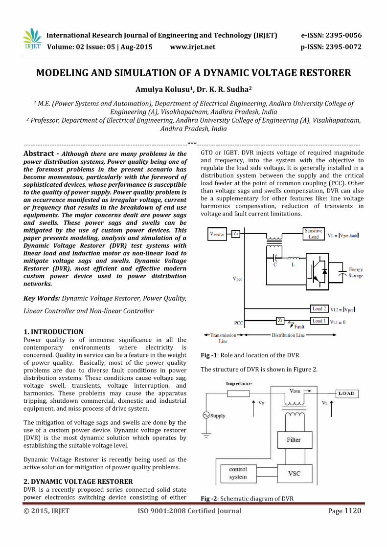
GTO or IGBT. DVR injects voltage of required magnitude and frequency, into the system with the objective to regulate the load side voltage. It is generally installed in a distribution system between the supply and the critical load feeder at the point of common coupling (PCC). Other than voltage sags and swells compensation, DVR can also be a supplementary for other features like: line voltage harmonics compensation, reduction of transients in voltage and fault current limitations.
Fig -1: Role and location of the DVR
The structure of DVR is shown in Figure 2.
Fig -2: Schematic diagram of DVR
International Research Journal of Engineering and Technology (IRJET) e-ISSN: 2395-0056
Volume: 02 Issue: 05 | Aug-2015 www.irjet.net p-ISSN: 2395-0072
© 2015, IRJET ISO 9001:2008 Certified Journal Page 1121
The DVR consists of:
2.1 Voltage Source Converter DC voltage is converted from the energy storage unit to a controllable three phase ac voltage. Sinusoidal Pulse Width Modulation scheme is normally used for firing the inverter switches.
2.2 Injection Transformer Injection transformer used in the DVR play an imperative role in ensuring the utmost consistency and efficiency of the reinstallation system.
2.3 Passive Filters Passive Filters are used to filter the harmonics. They are placed at the high voltage side of the DVR as placing the filters at the inverter side introduces phase angle shift which can disrupt the control algorithm.
2.4 Energy storage device/Control system The competency of energy storage device has a large impact on the compensation potential of the system. Compensation of real power is vital when large voltage sag occurs. Examples are dc capacitors, batteries, super-capacitors and flywheels.
2.5 DC Charging Circuit The dc charging circuit has two main tasks: The first task is to charge the energy source after a sag compensation event. The second task is to maintain dc link voltage at the nominal dc link voltage.
2.6 Control and Protection The control mechanism classically consists of hardware with programmable logic. All protective functions of the DVR should be implemented in the software. Differential current protection of the transformer, or short circuit current on the customer load side are only two examples of many protection functions possibility.
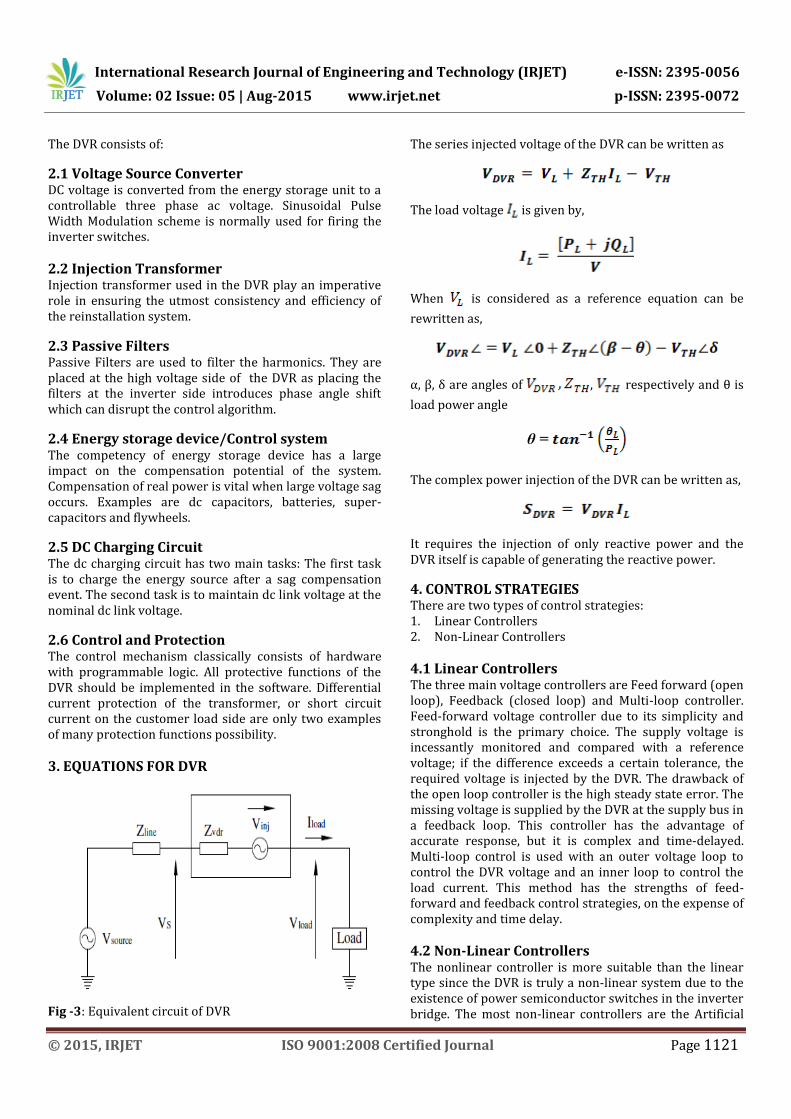
3. EQUATIONS FOR DVR
Fig -3: Equivalent circuit of DVR
The series injected voltage of the DVR can be written as
The load voltage is given by,
When is considered as a reference equation can be
rewritten as,
α, β, δ are angles of , respectively and θ is
load power angle
θ =
The complex power injection of the DVR can be written as,
It requires the injection of only reactive power and the DVR itself is capable of generating the reactive power.
4. CONTROL STRATEGIES There are two types of control strategies: 1. Linear Controllers 2. Non-Linear Controllers
4.1 Linear Controllers The three main voltage controllers are Feed forward (open loop), Feedback (closed loop) and Multi-loop controller. Feed-forward voltage controller due to its simplicity and stronghold is the primary choice. The supply voltage is incessantly monitored and compared with a reference voltage; if the difference exceeds a certain tolerance, the required voltage is injected by the DVR. The drawback of the open loop controller is the high steady state error. The missing voltage is supplied by the DVR at the supply bus in a feedback loop. This controller has the advantage of accurate response, but it is complex and time-delayed. Multi-loop control is used with an outer voltage loop to control the DVR voltage and an inner loop to control the load current. This method has the strengths of feed-forward and feedback control strategies, on the expense of complexity and time delay.
4.2 Non-Linear Controllers The nonlinear controller is more suitable than the linear type since the DVR is truly a non-linear system due to the existence of power semiconductor switches in the inverter bridge. The most non-linear controllers are the Artificial
International Research Journal of Engineering and Technology (IRJET) e-ISSN: 2395-0056
Volume: 02 Issue: 05 | Aug-2015 www.irjet.net p-ISSN: 2395-0072
© 2015, IRJET ISO 9001:2008 Certified Journal Page 1122
Neural Networks (ANN), Fuzzy Logic (FL) and Space Vector Pulse Width Modulation (SVPWM). ANN control method has adaptive and self-organization ability. ANN has intrinsic learning capability that can give enhanced precision by interpolation. FLCs are an attractive choice when precise mathematical formulations are impossible. When an FLC is used, the tracking error and transient overshoots of PWM can be noticeably reduced. SVPWM control strategy is to implement a space vector of the inverter voltage to acquire enhanced performance of the alternative is gained in low switching frequency conditions.
5. COMPENSATION TECHNIQUES There are four types of compensation techniques: 1. Pre-sag/Dip compensation 2. In-phase compensation 3. In-phase Advanced compensation 4. Voltage tolerance method with minimum energy
injection
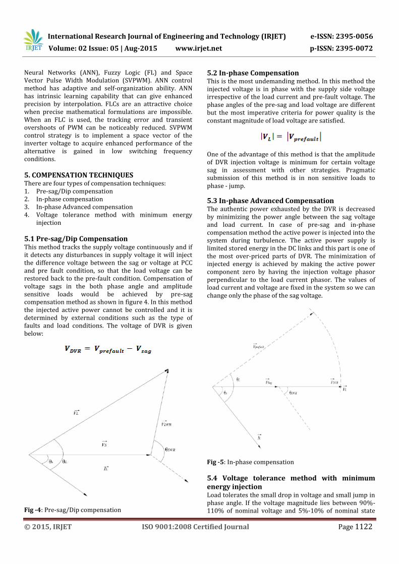
5.1 Pre-sag/Dip Compensation This method tracks the supply voltage continuously and if it detects any disturbances in supply voltage it will inject the difference voltage between the sag or voltage at PCC and pre fault condition, so that the load voltage can be restored back to the pre-fault condition. Compensation of voltage sags in the both phase angle and amplitude sensitive loads would be achieved by pre-sag compensation method as shown in figure 4. In this method the injected active power cannot be controlled and it is determined by external conditions such as the type of faults and load conditions. The voltage of DVR is given below:
Fig -4: Pre-sag/Dip compensation
5.2 In-phase Compensation This is the most undemanding method. In this method the injected voltage is in phase with the supply side voltage irrespective of the load current and pre-fault voltage. The phase angles of the pre-sag and load voltage are different but the most imperative criteria for power quality is the constant magnitude of load voltage are satisfied.
One of the advantage of this method is that the amplitude of DVR injection voltage is minimum for certain voltage sag in assessment with other strategies. Pragmatic submission of this method is in non sensitive loads to phase - jump.
5.3 In-phase Advanced Compensation The authentic power exhausted by the DVR is decreased by minimizing the power angle between the sag voltage and load current. In case of pre-sag and in-phase compensation method the active power is injected into the system during turbulence. The active power supply is limited stored energy in the DC links and this part is one of the most over-priced parts of DVR. The minimization of injected energy is achieved by making the active power component zero by having the injection voltage phasor perpendicular to the load current phasor. The values of load current and voltage are fixed in the system so we can change only the phase of the sag voltage.
Fig -5: In-phase compensation
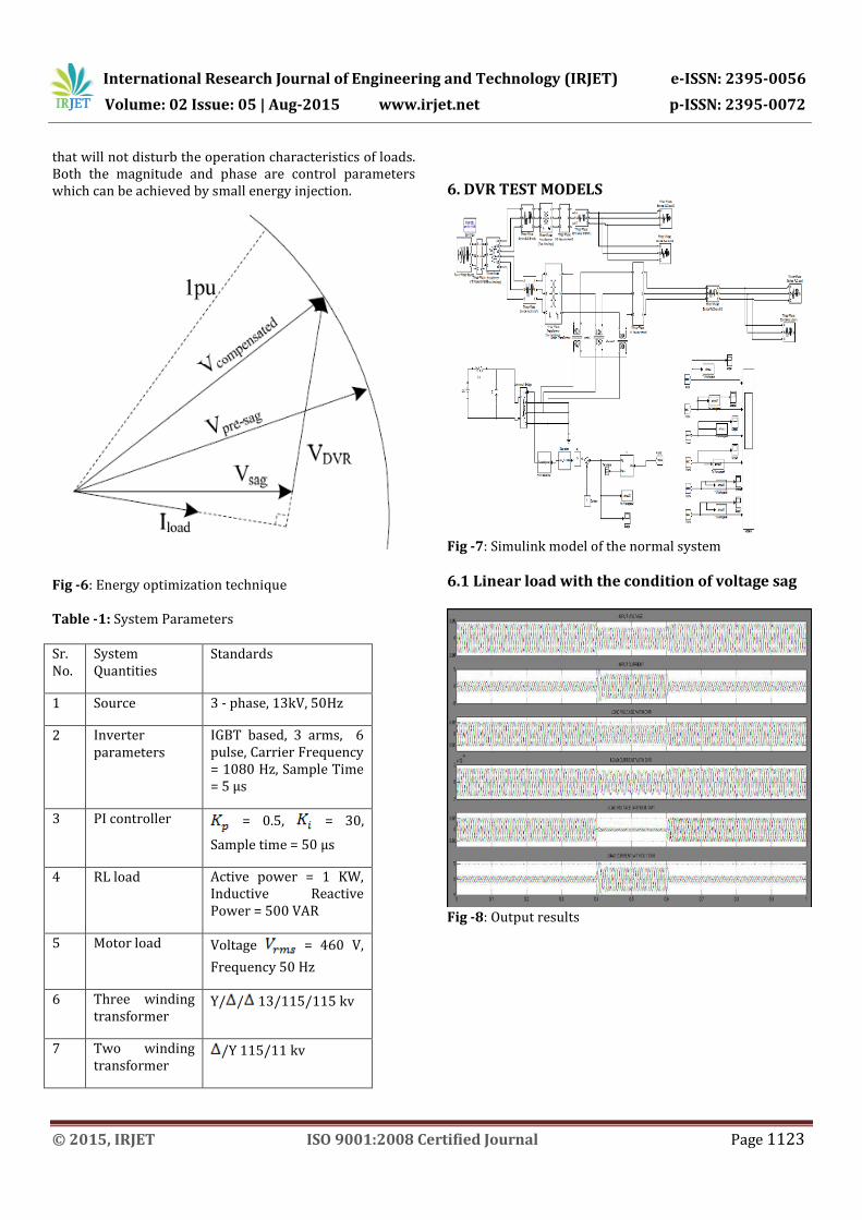
5.4 Voltage tolerance method with minimum energy injection Load tolerates the small drop in voltage and small jump in phase angle. If the voltage magnitude lies between 90%-110% of nominal voltage and 5%-10% of nominal state
International Research Journal of Engineering and Technology (IRJET) e-ISSN: 2395-0056
Volume: 02 Issue: 05 | Aug-2015 www.irjet.net p-ISSN: 2395-0072
© 2015, IRJET ISO 9001:2008 Certified Journal Page 1123
that will not disturb the operation characteristics of loads. Both the magnitude and phase are control parameters which can be achieved by small energy injection.
Fig -6: Energy optimization technique Table -1: System Parameters Sr. No.
System Quantities
Standards
1 Source 3 - phase, 13kV, 50Hz
2 Inverter parameters
IGBT based, 3 arms, 6 pulse, Carrier Frequency = 1080 Hz, Sample Time = 5 μs
3 PI controller = 0.5, = 30,
Sample time = 50 μs
4 RL load Active power = 1 KW, Inductive Reactive Power = 500 VAR
5 Motor load Voltage = 460 V,
Frequency 50 Hz
6 Three winding transformer
Y/ / 13/115/115 kv
7 Two winding transformer
/Y 115/11 kv
6. DVR TEST MODELS
Fig -7: Simulink model of the normal system
6.1 Linear load with the condition of voltage sag
Fig -8: Output results
International Research Journal of Engineering and Technology (IRJET) e-ISSN: 2395-0056
Volume: 02 Issue: 05 | Aug-2015 www.irjet.net p-ISSN: 2395-0072
© 2015, IRJET ISO 9001:2008 Certified Journal Page 1124
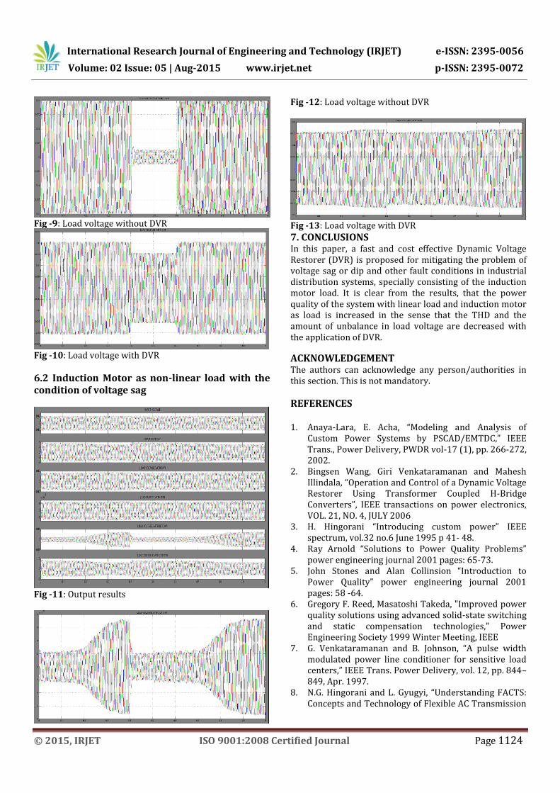
Fig -9: Load voltage without DVR
Fig -10: Load voltage with DVR
6.2 Induction Motor as non-linear load with the condition of voltage sag
Fig -11: Output results
Fig -12: Load voltage without DVR
Fig -13: Load voltage with DVR
7. CONCLUSIONS In this paper, a fast and cost effective Dynamic Voltage Restorer (DVR) is proposed for mitigating the problem of voltage sag or dip and other fault conditions in industrial distribution systems, specially consisting of the induction motor load. It is clear from the results, that the power quality of the system with linear load and induction motor as load is increased in the sense that the THD and the amount of unbalance in load voltage are decreased with the application of DVR.
ACKNOWLEDGEMENT The authors can acknowledge any person/authorities in this section. This is not mandatory.
REFERENCES 1. Anaya-Lara, E. Acha, “Modeling and Analysis of
Custom Power Systems by PSCAD/EMTDC,” IEEE Trans., Power Delivery, PWDR vol-17 (1), pp. 266-272, 2002.
2. Bingsen Wang, Giri Venkataramanan and Mahesh Illindala, “Operation and Control of a Dynamic Voltage Restorer Using Transformer Coupled H-Bridge Converters”, IEEE transactions on power electronics, VOL. 21, NO. 4, JULY 2006
3. H. Hingorani “Introducing custom power” IEEE spectrum, vol.32 no.6 June 1995 p 41- 48.
4. Ray Arnold “Solutions to Power Quality Problems” power engineering journal 2001 pages: 65-73.
5. John Stones and Alan Collinsion “Introduction to Power Quality” power engineering journal 2001 pages: 58 -64.
6. Gregory F. Reed, Masatoshi Takeda, "Improved power quality solutions using advanced solid-state switching and static compensation technologies," Power Engineering Society 1999 Winter Meeting, IEEE
7. G. Venkataramanan and B. Johnson, “A pulse width modulated power line conditioner for sensitive load centers,” IEEE Trans. Power Delivery, vol. 12, pp. 844–849, Apr. 1997.
8. N.G. Hingorani and L. Gyugyi, “Understanding FACTS: Concepts and Technology of Flexible AC Transmission
International Research Journal of Engineering and Technology (IRJET) e-ISSN: 2395-0056
Volume: 02 Issue: 05 | Aug-2015 www.irjet.net p-ISSN: 2395-0072
© 2015, IRJET ISO 9001:2008 Certified Journal Page 1125
Systems”, 1st edition, The Institute of Electrical and Electronics Enginee rs, 2000.
9. F. Z. Peng, H. Akagi, and A. Nabae, “Compensation characteristics of the combined system of shunt passive and series active filters,” IEEE Trans. Ind. Applicat., vol. 29, pp. 144–151, Jan./Feb. 1993.
10. M. H. Haque “Compensation of distribution system voltage sag by DVR and DSTATCOM” Power Tech Proceedings, 2001 IEEE Porto , Volume: 1 , 10-13 Sept. 2001 Pages:5 pp. vol.1
11. S. S. Choi, B. H. Li, and D. D.Vilathgamuwa, “Dynamic voltage restoration with minimum energy injection,” IEEE Trans. Power Syst., vol. 15,pp. 51–57, Feb. 2000
12. P.W. Lehn and MR. Iravani, “Experimental Evaluation of STATCOM Closed Loop Dynamics,” IEEE Trans. Power Delivery, vol. 13, no. 4, October 1998, pp. 1378 - 1384.
13. M. H. J. Bollen, “Understanding Power Quality Problems—Voltage Sags and Interruptions” Piscataway, New York: IEEE Press, 2000.
14. Mohan, T. M. Undeland, and W. P. Robbins, Power Electronics: Converters, Applications and Design . New York: Wiley, 1995
15. F.A.L. Jowder, “Design and analysis of dynamic voltage restorer for deep voltage sag and harmonic compensation”, Published in IET Generation, Transmission & Distribution Received on 17th October 2008, Revised on 2nd March 2009
16. Singh Mahesh, Tiwari Vaibhav, “ Modeling analysis and solution of Power Quality Problems”
17. BENACHAIBA Chellali, FERDI Brahim, Voltage Quality Improvement Using DVR, Electrical Power Quality and Utilisation, Journal Vol. XIV, No. 1, 2008
18. M. Jazayeri, H. Abdollahzadeh, “A Novel DVR Control System Design for Compensating all types of Voltage Sags Based on Pre-Fault Method”, European Journal of Scientific Research, ISSN 1450-216X Vol.33 No.1 (2009), pp.70-85, © EuroJournals Publishing, Inc. 2009
19. Norbert EDOMAH, “Effects of voltage sags, swell and other disturbances on electrical equipment and their economic implications”, Paper 0018, 20th International Conference on Electricity Distribution, Prague, 8-11 June 2009
20. Mehmet Tümay, Ahmet Teke, K. Çağatay Bayındır, M. Uğras Cuma, “Simulation and modeling of a dynamic voltage restorer”
21. N. Mohan, T.M. Undeland, W.P. Robbins, Power Electronics: Converters, Applications and Design, second ed., John Wiley & Sons, Neywork, 1995., pp. 471 - 475
22. J.G Neilsen, F. Blaabjerg, Comparison of system topologies for dynamic voltage restorer, in: Proceedings of IEEE Industry Applications Conference 2001, vol. 1, pp. 2397-2403
23. D. M. Vilathgamuwa, A.A.D.R. Perera, S.S. Choi, Voltage sag compensation with energy optimized dynamic voltage restorer, IEEE Trans. Power Deliver.18(3) (2003) 928-936.
24. IEEE Standards Board (1995), “IEEE Std. 1159-1995”, IEEE Recommended Practice for Monitoring Electric Power Quality”. IEEE Inc. New York.
BIOGRAPHIES
Amulya Kolusu is currently pursuing final year of the Integrated Dual Degree (B.E. + M.E.) in the department of Electrical Engineering with specialization in Power Systems and Automation from Andhra University College of Engineering, Visakhapatnam, India.
Dr. K. R. Sudha is a professor
for the department of Electrical
Engineering, Andhra University
College of Engineering,
Visakhapatnam, India. She has
obtained her doctorate degree
with specialization in Power
Systems.