simulation and implementation of dynamic voltage restorer
TRANSCRIPT

International Journal of Scientific & Engineering Research Volume 11, Issue 1, January-2020 382 ISSN 2229-5518
IJSER © 2020
http://www.ijser.org
Simulation and Implementation of Dynamic Voltage Restorer
Neha H. Chaudhari and Bijal Mehta Electrical Engineering Department
Sarvajanik College of Engineering and Technology
Surat, India.
e-mail: [email protected]
ABSTRACT-Voltage sag remains a serious
power quality (PQ) problem by being the most
common and causing more economic losses. As
the solution of power quality problems related to
voltage and current, a custom power device is
constructed which is named as Dynamic voltage
restorer (DVR). Selecting an appropriate
topology for DVR provides better solution of any
power quality issues. DVR remains present in
circuit as a buffer device during normal voltage
supply and controlled independently. For the sag
detection purpose DVR has implemented an
algorithm based on dq-0 transformation. The
proposed algorithm is designed to operate
correctly even during disturbance and varying
fault condition. DVR has a large energy storage
element as a source for compensation purpose
and that can perform for sever sags and specific
long duration sag. Hence the overall performance
of DVR based on sag detection time period and
its compensation is excellent.
I. INTRODUCTION Power quality is a term that means different
things to different people. The IEEE 1100
Standard identify power quality the same as
“the concept of powering and grounding
sensitive electronic equipment in a manner
that is suitable to the operation of that
equipment.” Power quality might also be
defined as “the measure, analysis, and
improvement of bus voltage, usually a load
bus voltage, to maintain that voltage to be a
sinusoid at rated voltage and frequency.”
Another clarity of power quality is, “the
provision of voltages and system design so
that the user of electric power can utilize electric energy from the distribution system
successfully without interference or
interruption.” Simpler explanation of power
quality is,” power quality is a set of electrical
boundries that allows a piece of equipment to
function in its manner without significant loss
of performance”
Power quality is one of today’s most
concerned areas of electric power system.
The power quality has serious economic
implications for consumers, utilities and
electrical equipment manufacturers. For
power quality crossing point such integration
of non-conservative technologies fuel cells,
wind turbines and photovoltaic are necessary
with utility grids. The power electronic
systems also provide to power quality
troubles. Under the deregulated environment,
in which electric utilities are possible to
compete with each other, the user’s
agreement becomes very necessary. The
contact of power quality troubles is all the
time more felt by users industrial,
commercial and even residential Sources of
poor Power Quality are listed as follows
• Adjustable –speed drives
• Switching Power supplies
• Arc furnaces
• Electronic
III. POWER QUALITY ISSUES
Voltage Sag: Voltage sag is identified as
the lessening of rms voltage to a value
between 0.1 and 0.9 p. u and enduring for
period between 0.5 cycle to 1 minute. Voltage
sags are frequently cause by system faults and
last for period range from 3 cycles to 30
cycles depending on the fault clearance time.
It is to be noted that under voltages can be
handle by voltage dip as the motor draws a
current up to 10 times the full load current
during the starting. Also, the power factor of
the starting current is generally poor.
IJSER
International Journal of Scientific & Engineering Research Volume 11, Issue 1, January-2020 383 ISSN 2229-5518
IJSER © 2020
http://www.ijser.org
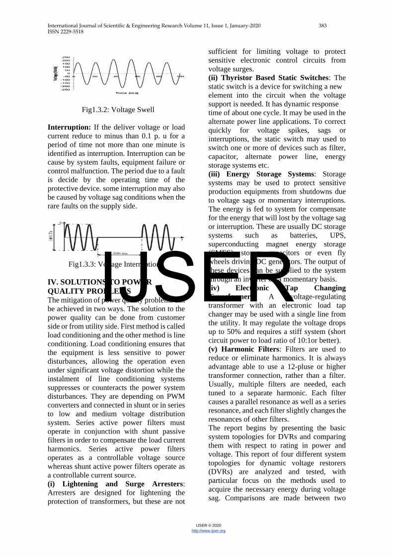
Fig1.3.2: Voltage Swell
Interruption: If the deliver voltage or load
current reduce to minus than 0.1 p. u for a
period of time not more than one minute is
identified as interruption. Interruption can be
cause by system faults, equipment failure or
control malfunction. The period due to a fault
is decide by the operating time of the
protective device. some interruption may also
be caused by voltage sag conditions when the
rare faults on the supply side.
Fig1.3.3: Voltage Interruption
IV. SOLUTIONS TO POWER
QUALITY PROBLEMS The mitigation of power quality problems can
be achieved in two ways. The solution to the
power quality can be done from customer
side or from utility side. First method is called
load conditioning and the other method is line
conditioning. Load conditioning ensures that
the equipment is less sensitive to power
disturbances, allowing the operation even
under significant voltage distortion while the
instalment of line conditioning systems
suppresses or counteracts the power system
disturbances. They are depending on PWM
converters and connected in shunt or in series
to low and medium voltage distribution
system. Series active power filters must
operate in conjunction with shunt passive
filters in order to compensate the load current
harmonics. Series active power filters
operates as a controllable voltage source
whereas shunt active power filters operate as
a controllable current source.
(i) Lightening and Surge Arresters:
Arresters are designed for lightening the
protection of transformers, but these are not
sufficient for limiting voltage to protect
sensitive electronic control circuits from
voltage surges.
(ii) Thyristor Based Static Switches: The
static switch is a device for switching a new
element into the circuit when the voltage
support is needed. It has dynamic response
time of about one cycle. It may be used in the
alternate power line applications. To correct
quickly for voltage spikes, sags or
interruptions, the static switch may used to
switch one or more of devices such as filter,
capacitor, alternate power line, energy
storage systems etc.
(iii) Energy Storage Systems: Storage
systems may be used to protect sensitive
production equipments from shutdowns due
to voltage sags or momentary interruptions.
The energy is fed to system for compensate
for the energy that will lost by the voltage sag
or interruption. These are usually DC storage
systems such as batteries, UPS,
superconducting magnet energy storage
(SMES), storage capacitors or even fly
wheels driving DC generators. The output of
these devices can be supplied to the system
through an inverter on a momentary basis.
(iv) Electronic Tap Changing
Transformer: A voltage-regulating
transformer with an electronic load tap
changer may be used with a single line from
the utility. It may regulate the voltage drops
up to 50% and requires a stiff system (short
circuit power to load ratio of 10:1or better).
(v) Harmonic Filters: Filters are used to
reduce or eliminate harmonics. It is always
advantage able to use a 12-pluse or higher
transformer connection, rather than a filter.
Usually, multiple filters are needed, each
tuned to a separate harmonic. Each filter
causes a parallel resonance as well as a series
resonance, and each filter slightly changes the
resonances of other filters.
The report begins by presenting the basic
system topologies for DVRs and comparing
them with respect to rating in power and
voltage. This report of four different system
topologies for dynamic voltage restorers
(DVRs) are analyzed and tested, with
particular focus on the methods used to
acquire the necessary energy during voltage
sag. Comparisons are made between two
IJSER

International Journal of Scientific & Engineering Research Volume 11, Issue 1, January-2020 384 ISSN 2229-5518
IJSER © 2020
http://www.ijser.org
topologies that can be realized with a
minimum amount of energy storage, with
energy taken from the grid during the voltage
sag, and two topologies that take energy from
stored energy devices during the voltage sag.
This comparison ranks the no-storage
topology with a passive shunt converter on
the load side first, followed by the stored
energy topology with a constant dc-link
voltage.
V. OVERVIEW OF TOPOLOGIES
FOR DVR DVRs operate to maintain the load supply
voltage at its rated value. The systems
considered in this paper are all three-phase,
and only active power flow is considered in
the analysis of their rating requirements. For
the purposes of this comparison, it is assumed
that the load has a high-power factor and the
passive converter absorbs only active power.
During voltage sag, the DVR injects a voltage
to restore the load supply voltages. In this
mode the DVR exchanges active and reactive
power with the surrounding system. If active
power is supplied to the load from the DVR,
it needs a source for this energy. Two types
of system are considered here, one using
stored energy to supply the delivered power
and the other having no significant internal
energy storage Basic principal of Dvr is to
transfer the voltage sag and swell
compensation value from Dc side of the
inverter to the injected transformer after
filter. The compensation capacity of a
particular DVR depends on the maximum
voltage injection capability and the active
power that can be supplied by the DVR. The
main function of the DVR is the protection of
sensitive loads from voltage sags/swells
coming from the supply network. Power
electronic converter injects appropriate
voltage based on voltage sag. It is fast, flexible,
& efficient solution to voltage sag problem
VI.SAG DETECTION METHOD One of the most important requirements for
DVR is that the controller should be able to
operate in real time manner. It means that the
whole compensating process is carried out
immediately, after a failure occurs, without
any delay. The very important factor that
influences the DVR speed most is the
reaction time of the implemented voltage sag
detection algorithm. The best DVR systems
are able to react within 1 ms.
There are several voltage sags detection
techniques, which can be used in DVR, such
as:
• Peak value method
• Missing voltage method
• RMS method
• Discrete Fourier transformation
• DQ transformation
• Hybrid transformation
DQ transformation (dq0 – direct-
quadrature-zero)
dq transformation is a mathematical
transformation used to simplify the analysis
of three-phase circuits. d and q quantities
Fig. Basic block diagram of Dynamic Voltage Restorer
IJSER

International Journal of Scientific & Engineering Research Volume 11, Issue 1, January-2020 385 ISSN 2229-5518
IJSER © 2020
http://www.ijser.org
represent rectangular two axis system, which
rotates with angular frequency ω in the case
of symmetric three-phase system, introducing
of the dq0 transformation reduces three AC
quantities (pu) to two DC quantities (d=1,
q=0). Any deviations from the steady state
condition in abc system reflect in changes of
dq0 values in real-time. For unbalanced and
asymmetric three phase system applies d≠0,
q≠0, 0≠0. According to this presumption it is
possible to obtain the difference between
desired and instant values dynamically.
Therefore, the output compensating voltage
can be controlled by PID regulators \The
resultant signal is converted back to abc
values.
VII. MATLAB SIMULATION
Fig.simulation model of Dynamic voltage restorer
Fig.simulation model of dynamic voltage restorer
MATLAB SIMULATION RESULT
Fig. voltage before DVR (Phase A)
Fig. Injected voltage (Phase A)
Fig. Compensated voltage (Phase A)
Fig. voltage before DVR (Phase B)
IJSER

International Journal of Scientific & Engineering Research Volume 11, Issue 1, January-2020 386 ISSN 2229-5518
IJSER © 2020
http://www.ijser.org
Fig. Injected voltage (Phase B)
Fig. Compensated voltage (Phase B)
Fig. Voltage before DVR (Phase C)
Fig. Voltage before DVR (Phase C)
Fig. Compensated voltage (Phase C)
Fig. Two phase voltage/current waveform result before/after
Dvr
IJSER

International Journal of Scientific & Engineering Research Volume 11, Issue 1, January-2020 387 ISSN 2229-5518
IJSER © 2020
http://www.ijser.org
Fig three phase voltage/current sag waveform result
before/after Dvr
VIII. CONCLUSION
By simulating the DVR model, it can provide
excellent voltage regulation against the power
quality issues and prevents the connection
from breakdown or any other damage. For
control technique of DVR system dq-
transformation control technique is used
because it provides high speed control, system
simplicity and can be used even during
distorted supply voltage waveform. Because of
the advanced control technique, DVR
responses to the power quality issue and
injects the appropriate voltage to the load by
measuring the source voltage and desired v
IX. REFERENCES
1. John Godsk Nielsen and Freed Bleiberg,
Fellow, “A Detailed Comparison of
System Topologies for Dynamic Voltage
Restorers” IEEE Transactions on
industry applications, Vol.41, No.5,
September/ 2005.
2. Takushi, IEEE, Hideaki Fujita, Member,
IEEE, and Hirofumi Akagi, Fellow,
“Design and Experimentation of a
Dynamic Voltage Restorer Capable of
Significantly Reducing an Energy-
Storage Element” IEEE Transactions on
industry applications, Vol.44, No. 3,
May/June 2008.
3. John Gods Nielsen, Michael IEEE, Hans
Nielsen, “Control and Testing of a
Dynamic Voltage restorer” IEEE
Transactions of Power Electronics
Vol.19. No.3 May 2004
4. Babaei, m. Farhadi Kangarlu, and M.
Sabahi, “Mitigation of voltage
disturbances using dynamic voltage
restorer based on direct converters,”
IEEE Trans. Power Del., vol. 25, no. 4,
pp. 2676-2683, Oct. 2010
5. E. Babaei, M. Farhadi Kangarlu, and M.
Sabahi, “Mitigation of voltage
disturbances using dynamic voltage
restorer based on direct converters,”
IEEE Trans. Power Del., vol. 25, no. 4,
pp. 2676-2683, Oct. 2010
6. Ahad. Kazemi and Ali. Azhdast
“Implementation of a Control Strategy
for Dynamic Voltage Restorer (DVR)
and Dynamic Voltage Compensator
(DVC)”. Lidong Zhang and Math H. J.
Bollen, Senior Member, “Characteristic
of Voltage Dips (Sags) in Power
Systems” IEEE Transactions on power
delivery, Vol.15, No.2, April 2000.
7. L. D. Zhang and M. H. J. Bollen,
“Characteristic of voltage dips (sags) in
power systems,” IEEE Trans. Power
Del., vol. 15, no. 2, pp. 827–832, Apr.
2000.
IJSER

International Journal of Scientific & Engineering Research Volume 11, Issue 1, January-2020 388 ISSN 2229-5518
IJSER © 2020
http://www.ijser.org
8. M.H.J. Bollen, “The influence of motor
re-acceleration on voltage sags,” IEEE
Trans. on Industry Applications, vol. 31,
pp. 667–674, 1995.
9. J. G. Nielsen, F. Blaabjerg, and N.
Mohan, “Control strategies for dynamic
voltage restorer compensating voltage
sags with phase jump,” in Proc. IEEE
APEC’01, vol. 2, 2001, pp. 1267–1273.
10. J. Praveen, B. Muni, S. Venkatesh and H.
Makthal, "Review of dynamic voltage
restorer for power quality improvement,"
in Proc. 2004 IEEE Industrial Electronics
Society Engineering Society Conf., pp.
749-754.
11. J. Nielsen, M. Newman, H. Nielsen, and
F. Blaabjerg, "Control and testing of a
dynamic voltage restore(dvr) at medium
voltage level," IEEE Trans. Power
Electron., vol. 19, no. 3, p. 806, May
2004.
12. L. Conrad, C. Grigg, K. Little,
"Predicting and preventing problems
associated with remote fault clearing
voltage dips," IEEE Trans. Industry
Applications, vol27, no. 1, pp. 167-172,
Jan/Feb 1991.
13. J. G. Nielsen, F. Blaabjerg, “A detailed
comparison of system topologies for
dynamic voltage restorers,” IEEE Trans.
Ind. Appl., vol. 41, no. 5, pp. 1272-1280,
Sep./Oct. 2005.
14. W.E. Brumsickle, R.S. Schneider, G.A.
Luck jiff, D.M. Divan, and M.F.
Cranachan, “Dynamic sag correctors:
cost-effective industrial power line
conditioning,” IEEE Trans. Ind. Appl.,
vol. 32, no. 1, pp. 212-217, Jan./Feb.
2001.
15. C. Meyer, R.W. DeDoncker, Y.W. Li,
and F. Blaabjerg, “Optimized control
strategy for a medium-voltage DVR—
theoretical investigations and
experimental results,” IEEE Trans.
Power Electron., vol. 23, no. 6, pp. 2746-
2754, Nov. 2008.
16. E. Babaei, M. Farhadi Kangarlu, and M.
Sabahi, “Compensation of voltage
disturbances in distribution systems using
single-phase dynamic voltage restorer,”
Electr. Power Syst. Res., vol. 80, no. 12,
pp. 1413- 1420, Dec. 2010.
17. H. Awad, J. Svensson, and M. Bollen,
“Mitigation of unbalanced voltage dips
using static series compensator,” IEEE
Trans. Power Electron., vol. 19, no. 3, pp.
837–846, May 2004.
18. Y. Sekine et al., “Voltage-sag
compensation,” Voltage-Sag
Compensation Committee Rep. Electric
Technol. Res. Assoc., vol. 46, no. 3, pp.
89–91, 1990. (in Japanese).
19. J. D. Li, S. S. Choi, and D. M.
Vilathgamuwa, “Impact of voltage phase
IJSER

International Journal of Scientific & Engineering Research Volume 11, Issue 1, January-2020 389 ISSN 2229-5518
IJSER © 2020
http://www.ijser.org
jump on loads and its mitigation,” in
Proc. 4th Int. Power Electronics Motion
Control Conf., vol. 3, Xian, China, Aug.
14–16, 2004, pp. 1762–1766.
20. C. Fitzer, M. Barnes, and P. Green,
“Voltage sag detection technique for a
dynamic voltage restorer,” IEEE Trans.
Ind. Appl., vol. 40, no. 1, pp. 203– 212,
Jan./Feb. 2004.
21. P. Cheng, C. Huang, C. Pan, and S.
Bhattacharya, “Design and
implementation of a series voltage sag
compensator under practical utility
conditions,” IEEE Trans. Ind. Appl., vol.
39, no. 3, pp. 844–853, May/Jun. 2003.
22. H. Fujita, S. Tominaga, and H. Akagi,
“Analysis and design of a DC voltage-
controlled static var compensator using
quad-series voltage source inverters,”
IEEE Trans. Ind. Appl., vol. 32, no. 4, pp.
970–978, Jul./Aug. 1996.
IJSER

International Journal of Scientific & Engineering Research Volume 11, Issue 1, January-2020 390 ISSN 2229-5518
IJSER © 2020
http://www.ijser.org
Fig. Voltage before DVR (Phase C)
Fig. Injected voltage (Phase C)
Fig. Compensated voltage (Phase C)
IJSER