a multilevel based dynamic voltage restorer- ultra … multilevel based dynamic voltage restorer-...
TRANSCRIPT

International Journal of Electrical and Computer Engineering.
ISSN 0974-2190 Volume 8, Number 2 (2016), pp. 167-181
© International Research Publication House
http://www.irphouse.com
A Multilevel Based Dynamic Voltage Restorer- Ultra
Capacitor for Improving Power Quality of
Distribution Grid
R. Madhan Mohan a, B. Murali Mohanb and T. Ashok Kumarc
aAssistent Professor, Dept. of EEE, AITS, Rajampet, Andhra Pradesh, India
E-mail:[email protected]
bAssistent Professor, Dept. of EEE, AITS, Rajampet, Andhra Pradesh, India
E-mail:[email protected]
cPG student, Dept. of EEE, AITS, Rajampet , Andhra Pradesh, India
E-mail:[email protected]
Abstract
In this project Cost of different energy storage technologies is diminishing
quickly and the integration of these innovations into the power grid is turning
into a reality with the approach of smart grid. Dynamic voltage restorer (DVR)
is one item that can give enhanced voltage list and swell pay with energy storage
integration. Ultra capacitors (UCAP) have low-energy density and high-control
thickness perfect qualities for pay of voltage lists and voltage swells, which are
both occasions that require high power for limited capacities to focus time. The
novel commitment of this paper lies in the mix of rechargeable UCAP-based
energy storage into the DVR topology.
Keywords: DC–DC converter, d–q control, DSP, dynamic voltage restorer
(DVR), energy storage integration, phase locked loop (PLL), sag/swell, Ultra
capacitor (UCAP).
I. INTRODUCTION
The concept of utilizing inverter-based dynamic voltage restorers (DVRs) for keeping
clients from transient voltage unsettling influences on the utility side was illustrated
interestingly. The creators propose the utilization of the DVR with rechargeable energy
storage at the dc-terminal to meet the active power requirements of the grid during
voltage unsettling influences. With a specific end goal to maintain a strategic distance

168 R. Madhan Mohan, B. Murali Mohan and T. Ashok Kumar
from and minimize the dynamic power infusion into the grid, the creators additionally
say an option arrangement which is to make up for the voltage sag by embeddings a
lagging voltage in quadrature with the line current. UCAP-based incorporation into the
DVR system is perfect, as the typical span of passing voltage droops and swells is in
the milliseconds to second’s range. UCAPs likewise have higher number of
charge/release cycles when contrasted with batteries and for the same module size,
UCAPs have higher terminal voltage when contrasted with batteries, which makes the
coordination simpler.
Fig. 1: One-line diagram of DVR with UCAP energy storage.
II. THREE-PHASE SERIES INVERTER
A. Power Stage
The one-line outline of the system is appeared in Fig. 1. The power stage is a three-
phase voltage source inverter, which is associated in series to the grid and is responsible
for compensating the voltage sags and swells; the model of the series DVR what's more,
its controller is appeared in Fig. 2. The inverter system comprises of an insulated gate
bipolar transistor (IGBT) module, its gate driver, LC channel, and a disengagement
transformer. The dc-link voltage Vdc is directed at 260 V for ideal execution of the
converter and the line–line voltage Vab is 208 V; taking into account these, the
modulation index m of the inverter is given by
Where n is the turn’s proportion of the isolation transformer. The goal of the
incorporated UCAPDVR system with active power capacity is to make up for

A Multilevel Based Dynamic Voltage Restorer- Ultra Capacitor for Improving …… 169
impermanent voltage sag (0.1–0.9 p.u.) and voltage swell (1.1–1.2 p.u.), which last
from 3 s to 1 min.
B. Controller Implementation
Fig. 2: Model of DVR and its controller with integrated higher order controller.
Phase advanced voltage rebuilding systems are mind boggling in implementation, in
any case, the essential purpose behind using these procedures is to minimize the active
power support and in this way the measure of energy storage requirement at the dc-link
so as to minimize the expense of energy storage. Nonetheless, the expense of energy
storage has been declining and with the availability of active power support at the dc-
link, complicated phase propelled procedures can be stayed away from and voltages
can be injected in-phase with the system voltage during a voltage sag or a swell
occasion. The control strategy requires the utilization of a PLL to discover the rotating
angle. The inverter controller execution depends on injected voltages in-phase with the
supply-side line–neutral voltages. This requires PLL for evaluating θ, which has been
executed utilizing the imaginary power technique portrayed. Taking into account the
assessed θ and the line–line source voltages, Vab, Vbc, and Vca (which are accessible
for this delta-sourced system) are changed into the d–q area and the line– impartial

170 R. Madhan Mohan, B. Murali Mohan and T. Ashok Kumar
segments of the source voltage Vsa, Vsb, and Vsc, which are not accessible, can then
be estimated using
These voltages are standardized to unit sine waves utilizing line– neutral system voltage
of 120Vrms as reference and looked at to unit sine waves in-stage with real system
voltages Vs from (3) to discover the infused voltage references Vref fundamental to
keep up a consistent voltage at the load terminals, where m is 0.52 from (1). In this way,
at whatever point there is a voltage sag on the other sag swell on the source side, a
comparing voltage Vinj2 is injected in-stage by the DVR and UCAP system to discredit
the impact and hold a consistent voltage VL at the loads end. The real active and
reactive power supplied by the arrangement inverter can be processed utilizing (4) from
the rms estimations of the infused voltage Vinj2a and load current ILa, and ϕ is the
phase distinction between the two waveforms.
III. UCAP AND BIDIRECTIONAL DC–DC CONVERTER
A. UCAP Bank Hardware Setup
The decision of the quantity of UCAPs fundamental for giving grid support relies on
upon the measure of bolster required, terminal voltage of the UCAP, dc-link voltage,
and circulation network voltages. In this paper, the trial setup comprises of three 48 V,
165F UCAPs (BMOD0165P048) fabricated by Maxwell Technologies, which are
associated in arrangement. In this manner, the terminal voltage of the UCAP bank is
144 V and the dc-link voltage is modified to 260 V. This would give the dc–dc converter
a practical operating duty ratio of 0.44–0.72 in the help mode while the UCAP is
releasing and 0.27– 0.55 in the buck mode while the UCAP is charging from the grid
through the dc-link and the dc–dc converter. It is reasonable also, cost-effective to
utilize three modules in the UCAP bank. Accepting that the UCAP bank can be released
to half of its underlying voltage (Vuc,ini) to definite voltage (Vuc,fin) from 144 to 72
A Multilevel Based Dynamic Voltage Restorer- Ultra Capacitor for Improving …… 171
V, which means profundity of release of 75%, the vitality in the UCAP bank accessible
for discharge is given by
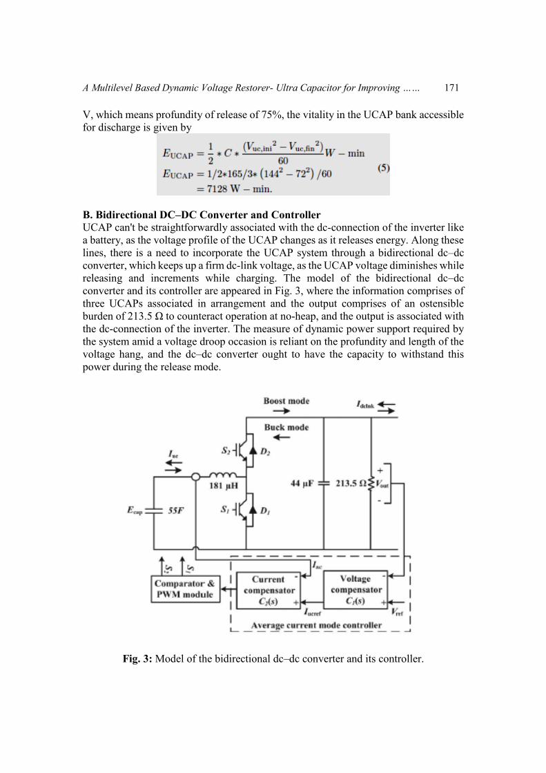
B. Bidirectional DC–DC Converter and Controller
UCAP can't be straightforwardly associated with the dc-connection of the inverter like
a battery, as the voltage profile of the UCAP changes as it releases energy. Along these
lines, there is a need to incorporate the UCAP system through a bidirectional dc–dc
converter, which keeps up a firm dc-link voltage, as the UCAP voltage diminishes while
releasing and increments while charging. The model of the bidirectional dc–dc
converter and its controller are appeared in Fig. 3, where the information comprises of
three UCAPs associated in arrangement and the output comprises of an ostensible
burden of 213.5 Ω to counteract operation at no-heap, and the output is associated with
the dc-connection of the inverter. The measure of dynamic power support required by
the system amid a voltage droop occasion is reliant on the profundity and length of the
voltage hang, and the dc–dc converter ought to have the capacity to withstand this
power during the release mode.
Fig. 3: Model of the bidirectional dc–dc converter and its controller.

172 R. Madhan Mohan, B. Murali Mohan and T. Ashok Kumar
The dc–dc converter ought to likewise be capable to work in bidirectional mode to have
the capacity to charge or absorb extra power from the grid during voltage swell
occasion. In this paper, the bidirectional dc–dc converter goes about as a support
converter while releasing power from the UCAP and goes about as a buck converter
while charging the UCAP from the lattice. A bidirectional dc–dc converter is required
as an interface between the UCAP and the dc-link following the UCAP voltage changes
with the measure of energy released while the dc-link voltage must be firm. Along these
lines, the bidirectional dc–dc converter is intended to work in support mode when the
UCAP bank voltage is somewhere around 72 and 144 V and the output voltage is
directed at 260 V. At the point when the UCAP bank voltage is underneath 72 V, the
bidirectional dc–dc converter is worked in buck mode and draws energy from the grid
to charge the UCAPs and the yield voltage is again controlled at 260 V.
Normal current mode control, which is broadly investigated in writing, is utilized to
manage the output voltage of the bidirectional dc–dc converter in both buck and help
modes while charging and releasing the UCAP bank. This strategy tends to be steadier
when contrasted with different strategies, for example, voltage mode control and crest
current mode control. Normal current mode controller is appeared in Fig. 3, where the
dc-link what's more, actual output voltage Vout is contrasted and the reference voltage
Vref and the error is gone through the voltage compensator C1(s), which creates the
normal reference current Iucref .When the inverter is releasing power into the grid
during voltage list occasion, the dc-link voltage Vout has a tendency to go underneath
the reference Vref and the mistake is certain; Iucref is sure and the dc–dc converter
works in support mode. At the point when the inverter is retaining power from the grid
during voltage swell occasion alternately charging the UCAP, Vout tends to increment
over the reference Vref and the blunder is negative; Iucref is negative and the dc–dc
converter works in buck mode. In this way, the indication of the error amongst Vout
and Vref decides the indication of Iucref also, along these lines the heading of operation
of the bidirectional dc–dc converter. The reference current Iucref is then contrasted with
the real UCAP current the compensator transfer functions, which provide a stable
response, are given by
EXTENSION
Multilevel inverter
Numerous industrial applications have begun to require higher power apparatus in
recent years. Some medium voltage motor drives and utility applications require
medium voltage and megawatt power level. For a medium voltage grid, it is
troublesome to connect only one power semiconductor switch directly. As a result, a
multilevel power converter structure has been introduced as an alternative in high

A Multilevel Based Dynamic Voltage Restorer- Ultra Capacitor for Improving …… 173
power and medium voltage situations. A multilevel converter not only achieves high
power ratings, but also enables the use of renewable energy sources. Renewable energy
sources such as photovoltaic, wind, and fuel cells can be easily interfaced to a multilevel
converter system for a high power application.
The term multilevel began with the three-level converter. Subsequently, several
multilevel converter topologies have been developed. However, the elementary concept
of a multilevel converter to achieve higher power is to use a series of power
semiconductor switches with several lower voltage dc sources to perform the power
conversion by synthesizing a staircase voltage waveform. Capacitors, batteries, and
renewable energy voltage sources can be used as the multiple dc voltage sources. The
commutation of the power switches aggregate these multiple dc sources in order to
achieve high voltage at the output; however, the rated voltage of the power
semiconductor switches depends only upon the rating of the dc voltage sources to which
they are connected.
A multilevel converter has several advantages over a conventional two-level converter
that uses high switching frequency pulse width modulation (PWM). The attractive
features of a multilevel converter can be briefly summarized as follows.
Staircase waveform quality: Multilevel converters not only can generate the
output voltages with very low distortion, but also can reduce the dv/dt stresses;
therefore electromagnetic compatibility (EMC) problems can be reduced.
Common-mode (CM) voltage: Multilevel converters produce smaller CM
voltage; therefore, the stress in the bearings of a motor connected to a multilevel
motor drive can be reduced. Furthermore, CM voltage can be eliminated by
using advanced modulation strategies such as that proposed.
Input current: Multilevel converters can draw input current with low distortion.
Switching frequency: Multilevel converters can operate at both fundamental
switching frequency and high switching frequency PWM.
IV Simulation results
4.1. SAG
Fig 4.1.1: Injected voltages Vinj2a (blue), Vinj2b red), and Vinj2c (green) during sag

174 R. Madhan Mohan, B. Murali Mohan and T. Ashok Kumar
Fig 4.1.2: Load voltages VLab (blue), VLbc (red), and VLca (green) during sag
Fig 4.1.3: Source voltages Vsab (blue), Vsbc (red), and Vsca (green) during sag
Fig 4.1.4: Source and load RMS voltages Vsrms and VLrms during sag

A Multilevel Based Dynamic Voltage Restorer- Ultra Capacitor for Improving …… 175
Fig 4.1.5: Voltages of dc–dc converter during voltage sag
Fig 4.1.6: Currents of dc–dc converter during voltage sag
Fig 4.1.7: Vinj2a (green) and Vsab (blue) waveforms during sag

176 R. Madhan Mohan, B. Murali Mohan and T. Ashok Kumar
Fig 4.1.8: Active power of grid, Load and inverter during voltage sag
Fig 4.1.9: Voltages of dc–dc converter during voltage sag
4.2 SWELL
Fig 4.2.1: Source voltages Vsab (blue), Vsbc (red), and Vsca (green) during swell
A Multilevel Based Dynamic Voltage Restorer- Ultra Capacitor for Improving …… 177
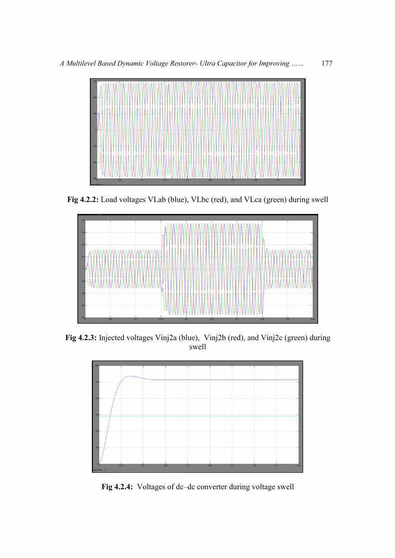
Fig 4.2.2: Load voltages VLab (blue), VLbc (red), and VLca (green) during swell
Fig 4.2.3: Injected voltages Vinj2a (blue), Vinj2b (red), and Vinj2c (green) during
swell
Fig 4.2.4: Voltages of dc–dc converter during voltage swell

178 R. Madhan Mohan, B. Murali Mohan and T. Ashok Kumar
Fig 4.2.5: Currents of dc–dc converter during voltage swell
Fig 4.2.6: Active power of grid, Load and inverter during voltage swell
Fig 4.2.7: Vinj2a (green) and Vsab (blue) waveforms during swell

A Multilevel Based Dynamic Voltage Restorer- Ultra Capacitor for Improving …… 179
Fig 4.2.8: Active power of grid, Load and inverter during voltage swell
Fig 4.2.9: Voltages of dc–dc converter during voltage swell
THD values for existing and proposed :
Sag ext 1.41%

180 R. Madhan Mohan, B. Murali Mohan and T. Ashok Kumar
Swell ext 4.91%
Sag proposed 0.32%

A Multilevel Based Dynamic Voltage Restorer- Ultra Capacitor for Improving …… 181
Swell proposed 0.45%
CONCLUSION
In this project the idea of integrating UCAP-based rechargeable energy storage to the
DVR system to enhance its voltage reclamation capacities is investigated .The control
system is straightforward what's more, depends on infusing voltages in-stage with the
system voltage what's more, is less demanding to actualize when the DVR system has
the capacity to give dynamic force. Normal current mode control is utilized to direct
the output voltage of the dc–dc converter because of its innately steady trademark. The
recreation of the UCAP-DVR system, which comprises of the UCAP, dc–dc converter,
and the matrix tied inverter, is completed utilizing PSCAD.
REFERENCES
[1] N. H. Woodley, L. Morgan, and A. Sundaram, “Experience with an inverter-
based dynamic voltage restorer,” IEEE Trans. Power Del., vol. 14, no. 3, pp.
1181–1186, Jul. 1999.
[2] S. S. Choi, B. H. Li, and D.M. Vilathgamuwa, “Dynamic voltage restoration
with minimum energy injection,” IEEE Trans. Power Syst., vol. 15, no. 1, pp.
51–57, Feb. 2000.
[3] D. M. Vilathgamuwa, A. A. D. R. Perera, and S. S. Choi, “Voltage sag
compensation with energy optimized dynamic voltage restorer,” IEEE Trans.
Power Del., vol. 18, no. 3, pp. 928–936, Jul. 2003.
[4] Y. W. Li, D. M. Vilathgamuwa, F. Blaabjerg, and P. C. Loh “A robust control
scheme for medium-voltage-level DVR implementation,” IEEE Trans. Ind.
Electron., vol. 54, no. 4, pp. 2249–2261, Aug. 2007.
[5] A. Ghosh and G. Ledwich, “Compensation of distribution system voltage using
DVR,” IEEE Trans. Power Del., vol. 17, no. 4, pp. 1030–1036, Oct.2002.

182 R. Madhan Mohan, B. Murali Mohan and T. Ashok Kumar