model dt3000 o oxygen analyzer - redkoh dt3000 oxygen analyzer version 1.17 5 introduction this...
TRANSCRIPT

Model DT3000O2 Oxygen Analyzer
This Manual Covers The Following systems:
Panel MountRack Mount
InsituExtractive
Version 1.17
Model DT3000 Oxygen AnalyzerVersion 1.17
2
Table of Contents
INTRODUCTION ................................................................................................................................................5
SPECIAL NOTE FOR INSITU SYSTEMS.......................................................................................................6
SECTION 1 ...........................................................................................................................................................7
ANALYZER OVERVIEW................................................................................................................................71.1 Configurations covered by this manual ..........................................................................................71.2 Analyzer Description ......................................................................................................................71.3 Theory of Operation .......................................................................................................................71.4 Electronic Controller......................................................................................................................81.5 Standard Analyzer Features ...........................................................................................................8
SECTION 2 .........................................................................................................................................................10
SPECIFICATIONS..........................................................................................................................................102.1 ANALYZER ...................................................................................................................................102.2 DETECTOR ..................................................................................................................................112.3 SAMPLE ......................................................................................................................................11OUTPUTS...................................................................................................................................................112.4 CALIBRATION .............................................................................................................................122.5 ALARM .........................................................................................................................................122.6 GASES ..........................................................................................................................................12
SECTION 3 .........................................................................................................................................................14
INSTALLATION ............................................................................................................................................143-1 OVERVIEW: .................................................................................................................................143.2 INSTALLATION............................................................................................................................143.3 PNEUMATIC CONNECTIONS....................................................................................................16
SECTION 4 .........................................................................................................................................................18
PARAMETERS DEFINITIONS .....................................................................................................................184.1 INTRODUCTION .........................................................................................................................184.2 BACK PURGE PERIOD...............................................................................................................184.3 BACK PURGE DURATION .........................................................................................................184.4 ROLLING AVERAGE ...................................................................................................................184.5 INSTANT AVERAGE ....................................................................................................................184.6 RECORDER RANGE....................................................................................................................194.7 O2 LOW ALARM SETPOINT.......................................................................................................194.8 HIGH ALARM SETPOINT ...........................................................................................................194.9 CAL PURGE TIME ......................................................................................................................204.10 SAMPLE & HOLD IN CAL ..........................................................................................................204.11 AUTO CALIBRATION..................................................................................................................204.12 SET TIME HH:MM ....................................................................................................................204.13 COMMS. SETUP ..........................................................................................................................20
SECTION 5 .........................................................................................................................................................21
UTILITIES DESCRIPTION............................................................................................................................215.1 INTRODUCTION .........................................................................................................................215.2 SIGNALS.......................................................................................................................................225.3 OUTPUTS.....................................................................................................................................225.4 DIGITAL IN..................................................................................................................................225.5 O2 CLAMP ...................................................................................................................................23
SECTION 6 .........................................................................................................................................................24
STARTUP AND OPERATION.......................................................................................................................24

Model DT3000 Oxygen AnalyzerVersion 1.17
3
6.1 INTRODUCTION .........................................................................................................................246.2 INITIAL STARTUP .......................................................................................................................246.3 SET UP PROCEDURE.................................................................................................................246.4 SETTING PARAMETERS.............................................................................................................25
SECTION 7 .........................................................................................................................................................35
CALIBRATION ..............................................................................................................................................357.1 INTRODUCTION .........................................................................................................................357.2 CALIBRATION .............................................................................................................................357.5 ZERO AND SPAN CHECK ..........................................................................................................377.7 ABORT TECHNIQUES FROM CALIBRATION...........................................................................37
SECTION 8 .........................................................................................................................................................38
DIAGNOSTIC DISCUSSION.........................................................................................................................388.1 INTRODUCTION .........................................................................................................................388.2 CALIBRATION FAULT................................................................................................................388.3 HIGH SENSOR TEMP .................................................................................................................388.4 LOW SENSOR TEMP ...................................................................................................................38
SECTION 9 .........................................................................................................................................................40
INSTRUMENT DESCRIPTION.....................................................................................................................409.1 INTRODUCTION .........................................................................................................................409.2 O2 CELL ANALOG CIRCUIT.......................................................................................................409.3 O2 CELL THERMOCOUPLE CIRCUIT ......................................................................................409.4 RELAY OUTPUTS........................................................................................................................409.5 INPUTS.........................................................................................................................................41
SECTION 10 .......................................................................................................................................................42
OXYGEN SENSOR ........................................................................................................................................4210.1 OXYGEN SENSOR - GENERAL...................................................................................................4210.2 ZIRCONIA SENSOR ASSEMBLY.................................................................................................42
SECTION 11 .......................................................................................................................................................43
TROUBLE SHOOTING..................................................................................................................................4311.1 OVERVIEW ..................................................................................................................................4311.2 SPECIAL TROUBLESHOOTING NOTES ...................................................................................4311.3 SENSOR TROUBLESHOOTING..................................................................................................4311.4 ELECTRONICS TROUBLESHOOTING ......................................................................................4511.5 ALARM MESSAGES.....................................................................................................................46
SECTION 12 .......................................................................................................................................................47
SERVICE AND NORMAL MAINTENANCE ...............................................................................................4712.1 OVERVIEW ..................................................................................................................................4712.2 PRELIMINARY CHECKS.............................................................................................................4712.3 SENSOR CALIBRATION: ............................................................................................................4812.4 SENSOR REMOVAL AND INSTALLATION: ...............................................................................4812.5 HEATER ELEMENT REPLACEMENT ........................................................................................4912.7 SPARE PARTS..............................................................................................................................49
13 WARRANTY........................................................................................................................................50
13.1 RETURNING EQUIPMENT TO THE FACTORY........................................................................50
14 MODBUS REGISTERS ......................................................................................................................52
APPENDIX I – DRAWINGS FOR INSITU UNIT, PANEL MOUNT CONTROL UNIT..........................54
APPENDIX II – DRAWINGS FOR INSITU UNIT, NEMA 4 CONTROL UNIT .......................................59
APPENDIX III – DRAWINGS FOR EXTRACTIVE RACK MOUNT CONTROL UNIT........................61

Model DT3000 Oxygen AnalyzerVersion 1.17
4
APPENDIX III – DRAWINGS FOR EXTRACTIVE RACK MOUNT CONTROL UNIT........................62
APPENDIX IV – DRAWINGS FOR SELF CONTAINED CONTROL UNIT ............................................66
Model DT3000 Oxygen AnalyzerVersion 1.17
5
Introduction
This manual contains instructions for the operation and programming of a DT3000Oxygen analyzer.
This analyzer has two basic designs:
Insitu System – This refers to an installation where the probe for collectingthe gas sample has the Oxygen sensor (O2 Head) as an integral part of theprobe. This is typically used on a positive or neutral (where an eductor isadded) pressure stack or duct and the sample is forced through the sampleline to the control unit.
Extractive System – This refers to an installation where the probe forcollecting the gas sample is separate from the Oxygen sensor. This istypically used on a negative pressure stack or duct where the sample isdrawn through the sample line by a vacuum pump.
In addition to the different designs, there are different control configurations:
Panel Mount Control – This configuration houses the control system onlyand is typically used with the Insitu design. However it could be used wherethe extractive Oxygen sensor and probe are remotely located.
NEMA 4 Control - This configuration houses the control system only in aNEMA 4 rated wall mount cabinet, and is typically used with the Insitu design.However it could be used where the extractive Oxygen sensor and probe areremotely located.
Rack Mount Control - This configuration houses the control system and theOxygen sensor (O2 Head) on a 19” rack mount panel, and is typically usedwith the Extractive design. The pump is located elsewhere.
Self Contained Control – The self contained control is an Extractive systemwhere the control, vacuum pump and Oxygen sensor are all located in asingle NEMA 4 wall mount cabinet.
Drawings of these various configurations are located in the Appendix of this manual.
Model DT3000 Oxygen AnalyzerVersion 1.17
6
Special Note for Insitu Systems
The Insitu DT3000 is based on gas be presented to the Oxygen sensor(O2 Head) sensor. There may be circumstances that exist where thegas to be measured does not reach the sensor (in a neutral pressureduct, for instance). For those circumstances a stainless steel eductor(see drawing DT3000-07) has been supplied with your DT3000 system.
An eductor is a device that produces suction when air is introduced intoit. This suction draws the flue gas up the probe and insures itpresentation to the sensor.
If the system calibrates properly but the O2 reading from the gas beingmonitored drifts aimlessly in the higher percentile range, install theeductor in the system.
Section 2 of the manual has air pressure versus sample flow rates forcorrect flow adjustment.
Plant air can be used to feed the eductor but instrument grade air isrecommended for maintenance free operation of the eductor.
Model DT3000 Oxygen AnalyzerVersion 1.17
7
SECTION 1
ANALYZER OVERVIEW
1.1 Configurations covered by this manual
InsituExtractivePanel MountNEMA 4 MountRack Mount
1.2 Analyzer Description
The Datatest Model DT3000 Oxygen Analyzer is designed for continuousmeasurement of Oxygen concentration in a non-combustible or low-levelcombustible flowing gas sample. The Model DT3000 reflects the state of theart in detector and electronic hardware design. For extractive O2 systemsusing a sampling system (user provided), sample gas is piped to a Zirconiasensor mounted in the O2 Head. The O2 Head can either be mounted in theanalyzer unit (Controller), or remotely mounted. For Insitu O2 systems, thesensor is located directly on the probe in the stack or duct.
The electronic package incorporated within the DT3000 featuresmicroprocessor technology that greatly expands the versatility andcapabilities of the Oxygen Analyzer.
The display prompts the operator during the set-up routines, shows instantand average concentration of sample, high and low alarm set points, recorderrange, and more. A standard Modbus RTU (RS232, or 485, or 422)communication port is also provided to allow two-way communication withdata acquisition systems.
The 16-key keypad provides a completely sealed keyboard to assure that itstouch-sensitive contacts are not subject to dust or moisture.
1.3 Theory of Operation
The measurement of oxygen is accomplished by reading voltage developedacross a heated Zirconia cell that is induced by uneven concentrations ofoxygen. The O2 sensor consists of a Zirconia Cell, which is coated with
Model DT3000 Oxygen AnalyzerVersion 1.17
8
porous metal electrodes. The sample gas is supplied to the sample side ofthe cell by an external source and reference air (ambient air) is provided tothe opposite side of the cell.
Electronic temperature control maintains proper cell temperature.
For best results, supply the analyzer with clean, dry, instrument air (20.95%oxygen) as a reference gas. With the sensor at its operating temperature,and unequal oxygen concentrations across the cell, oxygen ions travel fromhigh partial pressure side to low partial pressure side. This characteristicenables the oxygen analyzer to provide exceptional sensitivity at low oxygenconcentration.
WARNING
Do not use this analyzer on flammable samples, use explosion-proofversion for analysis of flammable samples. If used for analysis ofexplosive gases, internal leakage of sample could result in explosioncausing death, personal injury, or property damage.
The DT3000 Oxygen Analyzer measures net oxygen concentration in thepresence of all products of combustion, including water vapor. There theanalysis is made on a ‘wet’ gas basis.
1.4 Electronic Controller
The DT3000 microprocessor controller electronically controls sensortemperature, heater power, display measurements, functions, and providesisolated analog outputs that are proportional to measured oxygenconcentrations. Normally open (N.O.) relay contacts are provided for low andhigh alarm set points, zero, span calibration, back purge, and system fault.
Temperature of the oxygen cell is maintained constant by modulating the dutycycle of the sensor’s heater. The electronics accepts millivolt signalgenerated by the sensing cell and converts this voltage signal to an analogisolated 4-20mA current output to be used by remotely connected recordingdevices.
1.5 Standard Analyzer Features
1. Recalibration through a 16-key tactile feedback membrane keyboard.
Model DT3000 Oxygen AnalyzerVersion 1.17
9
2. Prompts on a 4-line by 20-character LCD display help an operator duringthe various set-up routines (such as for concentration of sample, averageconcentration, alarms levels, etc.).
3. Standard RS-232/485/422 ports (unit ships in RS232 configuration) toallow bi-directional communication with other data acquisition systems.
4. Completely sealed keyboard for reliable long term operation.
5. Alarm indications of fault conditions with independent set points alarms.
6. Standard isolated current (4-20mA) outputs.
7. Continuous monitoring of the sensor’s condition.
Model DT3000 Oxygen AnalyzerVersion 1.17
10
SECTION 2
SPECIFICATIONS
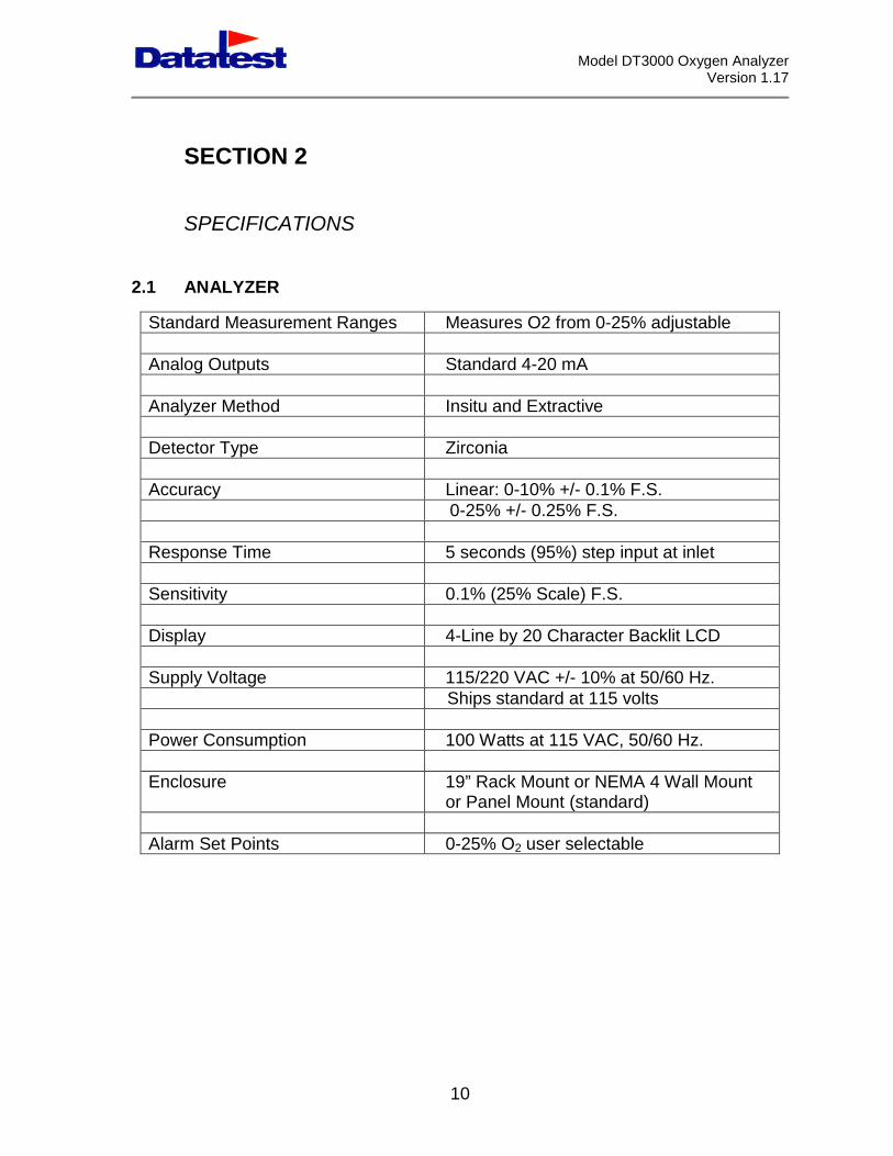
2.1 ANALYZER
Standard Measurement Ranges Measures O2 from 0-25% adjustable
Analog Outputs Standard 4-20 mA
Analyzer Method Insitu and Extractive
Detector Type Zirconia
Accuracy Linear: 0-10% +/- 0.1% F.S.0-25% +/- 0.25% F.S.
Response Time 5 seconds (95%) step input at inlet
Sensitivity 0.1% (25% Scale) F.S.
Display 4-Line by 20 Character Backlit LCD
Supply Voltage 115/220 VAC +/- 10% at 50/60 Hz.Ships standard at 115 volts
Power Consumption 100 Watts at 115 VAC, 50/60 Hz.
Enclosure 19” Rack Mount or NEMA 4 Wall Mountor Panel Mount (standard)
Alarm Set Points 0-25% O2 user selectable

Model DT3000 Oxygen AnalyzerVersion 1.17
11
2.2 DETECTOR
Type Zirconia
Temperature 1000°F. Controlled by microprocessorwith readout on LCD Display
2.3 SAMPLE
Sampling Rate ExtractiveSystem
Approximately 5.0 SCFH (473 cc/min)…. Note.For Extraction using and eductor:
Assuming sample and air lines are ¼’ tube:Air Pressure of 5/10/15 Psi will pull a sample of3.5/7/10 SCFH
Sampling RateInsitu System
Should the probe be situated in an area wherethe pressure at the sensor is inadequate, The useof an eductor, supplied as standard with yourDatatest Probe will allow you to overcome thisnegative pressure and pull the gas from thestream, up the probe, and allow it to be presentedto the sensor. The vent hole at the top of theprobe must remain plugged when using aneductor. Some guidelines for eduction are asfollows:
Assuming air lines are ¼’ tube, air Pressure of5/8/10/12 psi will pull a sample of 3/5/5.5/7 SCFH
Response Time 95% of full scale within 5 seconds
OUTPUTS
LCD Display 4-line by 20 character LCD
Analog 4-20mA
Serial Ports RS-232/459/422 to a computer for bi-directionalcommunication. RS232 ships as standard
Relay Outputs (N.O.SPST, 1A)
System alarm, Back Purge, O2 low, O2 high, Zero,and Span

Model DT3000 Oxygen AnalyzerVersion 1.17
12
2.4 CALIBRATION
External Standard calibration procedurepermits the introduction of zero andspan gases through the sampleport.
Cal Gas Target Values Standard zero and span valuesentered via keypad.
Frequency Via external digital (potential free)inputs
Recommended Calibration GasMixture
Zero: 2% O2, Balance N2; Span:8% O2, Balance N2
Recommended Calibration GasFlow Rate
5.0 SCFH (473 cc/min)
2.5 ALARM
Concentration 0-25%, user selectable
System Denotes a system failure.
Internal Audible 60 dB alarm
External N.O. SPST Relay Contacts, 10 AmpAC/DC
Alarm Condition Reported to screen, andcommunications output port.
2.6 GASES
Reference Air No more than 1 SCFH at .1 psigrequired.
Ports 1/4” tubing connections
Model DT3000 Oxygen AnalyzerVersion 1.17
13
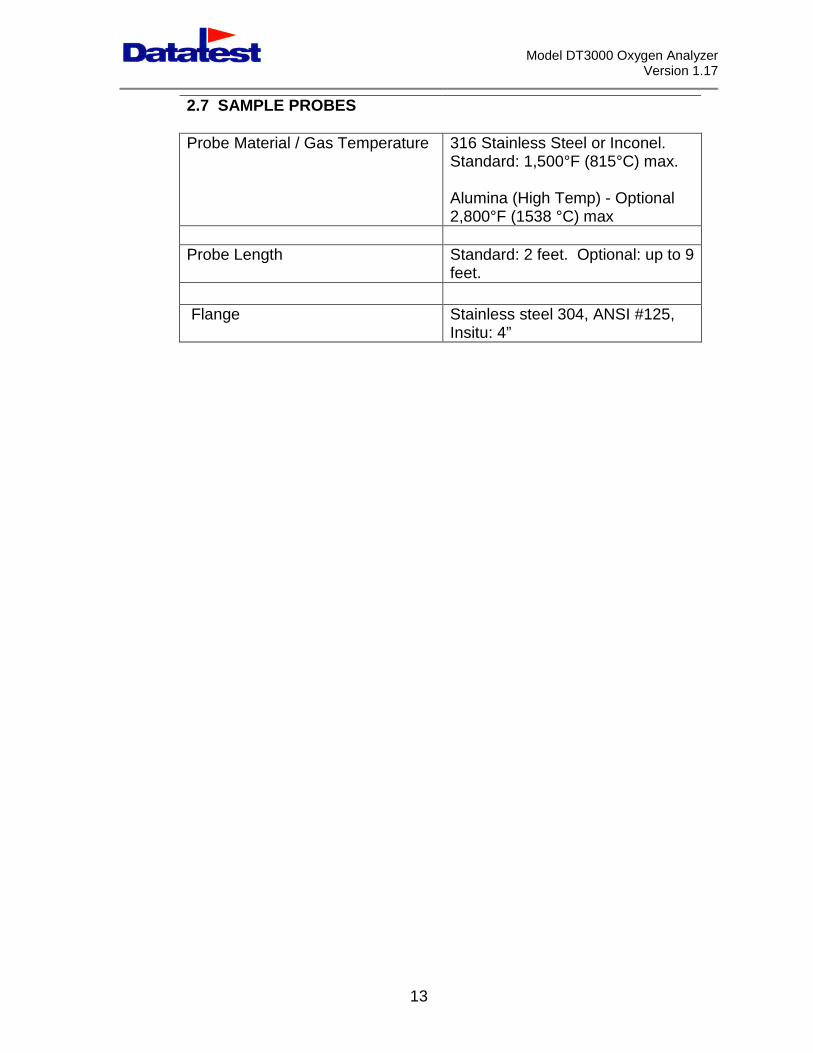
2.7 SAMPLE PROBES
Probe Material / Gas Temperature 316 Stainless Steel or Inconel.Standard: 1,500°F (815°C) max.
Alumina (High Temp) - Optional2,800°F (1538 °C) max
Probe Length Standard: 2 feet. Optional: up to 9feet.
Flange Stainless steel 304, ANSI #125,Insitu: 4”
Model DT3000 Oxygen AnalyzerVersion 1.17
14
SECTION 3
INSTALLATION
3-1 OVERVIEW:
This section covers the installation of the Model DT3000 Oxygen Analyzer.When installing, observe the following precautions.
a. Do not operate this analyzer in an explosive atmosphere.
b. The control unit mounting location must be dry and not exposed tofreezing temperatures. Formation of condensation must be avoided.Do not place the control cabinet in direct sunlight.
c. Ambient temperatures must be between 32°F and 112°F (0°C and45°C). If the analyzer is used outside its operating range, accuracyand error limit cannot be guaranteed.
d. Eliminate vibrations. Structural vibrations, machinery vibrations, etc.will affect the operation and life of the analyzer. Find a vibration freestructural wall or a similar place for firm mounting of the controller.
e. If the unit is to be extractive, mount the analyzer as close to thesampling point as possible. This will reduce dead time. If a suitableinstallation place cannot be found close enough, the dead time due tolonger lines can be made up by a higher sampling delivery rate.
f. All wiring must be in accordance with national and local wiring codes.
3.2 INSTALLATION
Mechanical Installation
The O2 Analyzer control unit requires installation in a location where thetemperature range is between 32°F and 112°F (0-45°C).
Model DT3000 Oxygen AnalyzerVersion 1.17
15
Electrical Connections: See Appendix for drawings.
1. Power input: 115 or 220 VAC, +/-10%, single phase, 50 or 60 Hz,250 watts maximum.
2. The power cable should comply with the safety regulations in theuser’s country and should never be smaller than 12 AWG (14 SWG).
3. ANALOG SIGNALS: The Model DT3000 has standard 4-20mAcurrent outputs. The current outputs are calibrated for a 250-ohm load.This output signal can be fed to an external load such as a recorder, orthe signal can be used to drive a single external meter or recorder, asdesired.
4. RS-232/422/485 CONNECTIONS: The Model DT3000 is equippedwith a serial port that can be configured for RS-232 or RS-422 or RS-485. This allows the Model DT3000 to report its data to a DCS orother computer via a Serial Modbus RTU Protocol.
5. DIGITAL INPUTS: There are several digital inputs on the ModelDT3000. These inputs permit external devices to initiate zero andspan checks. A will initiate a zero calibration and a 120 Vac input toTB1/2 will initiate the span.
6. RELAY OUTPUTS: Several relay outputs are available on the rearpanel TB1, terminal strip. They are:
TB1 DESCRIPTION
10 System Fault11 System Fault12 Back Purge13 Back Purge14 O2 Low Alarm15 O2 Low Alarm16 O2High Alarm17 O2 High Alarm18 Zero Cal Solenoid Valve19 Zero Cal Solenoid Valve20 Span Cal Solenoid Valve21 Span Cal Solenoid Valve

Model DT3000 Oxygen AnalyzerVersion 1.17
16
TB1 Layout on back of Control
3.3 PNEUMATIC CONNECTIONS
The following gases are needed to accurately operate the Model DT3000.
1. Zero Gas with cylinder regulator capable of being set toapproximately 2-5 psig. Consumption will be approximately about 5.0SCFH. This gas is connected to the Cal Port of the insitu probe using1/4” tubing. The zero point O2 concentration should be approximately1 to 2% O2.
2. Span Gas with cylinder regulator capable of being set toapproximately 2-5 psig. Consumption will be approximately about 5.0SCFH. This gas is connected to the Cal Port of the insitu probe using1/4” tubing. The zero point O2 concentration should be approximately8.0% to 14.0% O2.
3. Since the sensor operates with respect to a reference air, there maybe occasions where the ambient air on the atmospheric side of the cellneeds supplemental air. Connect this via a regulator capable of beingset to 1 psig. Consumption will be approximately 1.0 CFH. This isconnected to the insitu probe air reference port.
4. Back purge air should be connected via a Back Purge solenoid.This requires a line or tee from the exit port of the solenoid into theBack Purge port of the O2 insitu probe (see drawing DT3000-07).Connect the back purge air via a regulator capable of being set to 40psig. Assuming air lines are ¼’ tube, air Pressure of 5/8/10/12 psi will

Model DT3000 Oxygen AnalyzerVersion 1.17
17
pull a sample of 3/5/5.5/7 SCFH. This is connected to the insitu probepurge air port.
When the back purge solenoid is activated there is an immediate blastof pressurized air which flushes or back flushes the O2 insitu sampleprobe filter. In order for a pressurized blast of air to hit the probe filterthe connecting lines to the solenoid should be as short as possible toavoid restriction.
Model DT3000 Oxygen AnalyzerVersion 1.17
18
SECTION 4
PARAMETERS DEFINITIONS
4.1 INTRODUCTION
This section goes through each of the parameters that are needed by theModel DT3000 for operation. The discussion here will detail the full featuresand limits of these parameters. The order of presentation will be the samehere as the order they appear in the parameter routine.
4.2 BACK PURGE PERIOD
This parameter determines the period of time between back purges of thesample probe filter. The back purge period is entered here in hours. Thehigher the particulate concentration in the flue gas the more often the filtershould be cleaned, and the shorter this time must be. Back purge is inhibitedduring a calibration period.
4.3 BACK PURGE DURATION
The duration of the back purge is set in seconds and is the time that the blowback solenoid is activated and there is back flow across the filter. In practiceit is generally the initial blast of high-pressure gas that dislodges theparticulates in the filter. Therefore this time can be set quite low (ex. 10 sec).
4.4 ROLLING AVERAGE
The Rolling Average is used to set the time frame for the O2 reading rollingaverage that is reported to the authorities. The rolling average is the numberdisplayed on the Run Screen next to Avg.
4.5 INSTANT AVERAGE
The instant average is the block of time that an O2 reading is averaged over.It is different from a rolling average in that the time frame is discrete and thevalue is discarded at the end of the period. This instant average is usedprimarily for trim control.
Model DT3000 Oxygen AnalyzerVersion 1.17
19
4.6 RECORDER RANGE
The recorder range relates to the analog signal available at the recorderterminals on the rear of the Model DT3000. This analog signal is obtainedfrom the digital output and is thus a calibrated signal directly proportional tothe instantaneous concentration the Model DT3000 detector is seeing. Thissignal is 4-20 mA. The full-scale value for 20mA is set by the Recorder Rangeparameter.
4.7 O2 LOW ALARM SETPOINT
A Low O2 concentration alarm is set to provide relay contacts and alarmmessages for a low O2 condition. If the concentration goes below the low setpoint value, two things happen.
1. The display shows the statement ‘LOW O2 ALARM’ at thebottom of the run display.
2. The low concentration alarm terminals on the rear of theModel DT3000 will have a contact closure between them.
When the concentration rises above the low set point the relay closureopens and the alarm on the display is removed.
4.8 HIGH ALARM SETPOINT
A High O2 concentration alarm is set to provide relay contacts and alarmmessages for a high O2 condition. If the concentration goes above the highset point value, two things happen.
1. The display shows the statement ‘HIGH O2 ALARM’ at thebottom of the run display.
2. The high concentration alarm terminals on the rear of theModel DT3000 will have a contact closure between them.
When the concentration falls below the high set point the relay closureopens and the alarm on the display is removed.
The display indication of an alarm condition alerts the operator tocheck the alarm status menu.
Model DT3000 Oxygen AnalyzerVersion 1.17
20
4.9 CAL PURGE TIME
The Cal Purge Time is used in the various methods for calibration. It is set inseconds in the parameter routine but in practice it counts down in seconds.This allows sufficient time for the various gases to flush the sample lines andO2 cell prior to taking any concentration readings.
4.10 SAMPLE & HOLD IN CAL
The sample and hold in cal is used when the DT3000 is being used for trimcontrol and the calibration cycle could cause a boiler upset. When an autocalibration cycle is initiated the last O2 reading on the 4-20ma output. This isheld until the calibration cycle is complete.
4.11 AUTO CALIBRATION
This function allows for an automatic calibration of the instrument on a clocktimed basis. This will use relay contacts to open solenoid valves to performthe calibration
4.12 SET TIME HH:MM
The control contains a real time clock that is set in military time. Variousroutines are automatically initiated based on the time of day. It is importantthat this time is set accurately.
4.13 COMMS. SETUP
When communicating with a remote device (DCS, PC, PLC, etc.), each O2
analyzer must have a unique ID number between 0 and 255. The actual IDnumber assigned can be anywhere in the appropriate range but ID numbersmust never be duplicated.
Following a parameter routine, the Model DT3000 returns to the Main Menu.The operator must select the next operation from this menu
Model DT3000 Oxygen AnalyzerVersion 1.17
SECTION 5
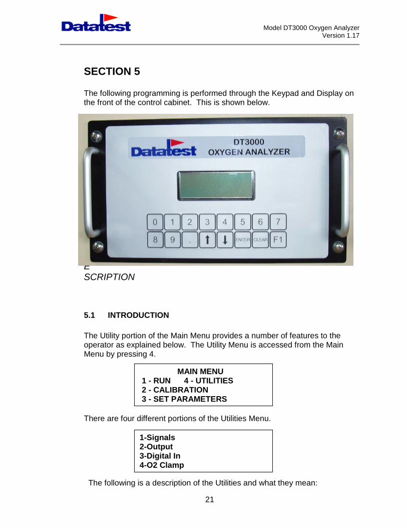
The following programming is performed through the Keypad and Display onthe front of the control cabinet. This is shown below.
UTILITIES
DESCRIPTION
5.1 INTRODUCTION
The Utility portion of the Main Menu provides a number of features to theoperator as explained below. The Utility Menu is accessed from the MainMenu by pressing 4.
There are four
The following
MAIN MENU1 - RUN 4 - UTILITIES2 - CALIBRATION
different portions of the Utilities Menu.
3 - SET PARAMETERS
1-Signals2-Output3-Digital In
21
is a description of the Utilities and what they mean:
4-O2 Clamp
Model DT3000 Oxygen AnalyzerVersion 1.17
22
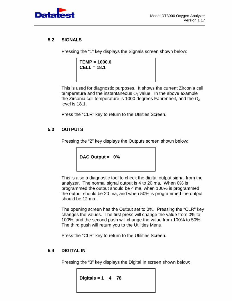
5.2 SIGNALS
Pressing the “1” key displays the Signals screen shown below:
This is used for diagnostic purposes. It shows the current Zirconia celltemperature and the instantaneous O2 value. In the above examplethe Zirconia cell temperature is 1000 degrees Fahrenheit, and the O2
level is 18.1.
Press the “CLR” key to return to the Utilities Screen.
5.3 OUTPUTS
Pressing the “2” key displays the Outputs screen shown below:
This is also a diagnostic tool to check the digital output signal from theanalyzer. The normal signal output is 4 to 20 ma. When 0% isprogrammed the output should be 4 ma, when 100% is programmedthe output should be 20 ma, and when 50% is programmed the outputshould be 12 ma.
The opening screen has the Output set to 0%. Pressing the “CLR” keychanges the values. The first press will change the value from 0% to100%, and the second push will change the value from 100% to 50%.The third push will return you to the Utilities Menu.
Press the “CLR” key to return to the Utilities Screen.
5.4 DIGITAL IN
Pressing the “3” key displays the Digital In screen shown below:
TEMP = 1000.0CELL = 18.1
DAC Output = 0%
Digitals = 1__4__78
Model DT3000 Oxygen AnalyzerVersion 1.17
23
This screen will show which digital inputs are presently active. Thedisplay may show anywhere from zero to all eight inputs as isapplicable at any point in time.
Press the “CLR” key to return to the Utilities Screen.
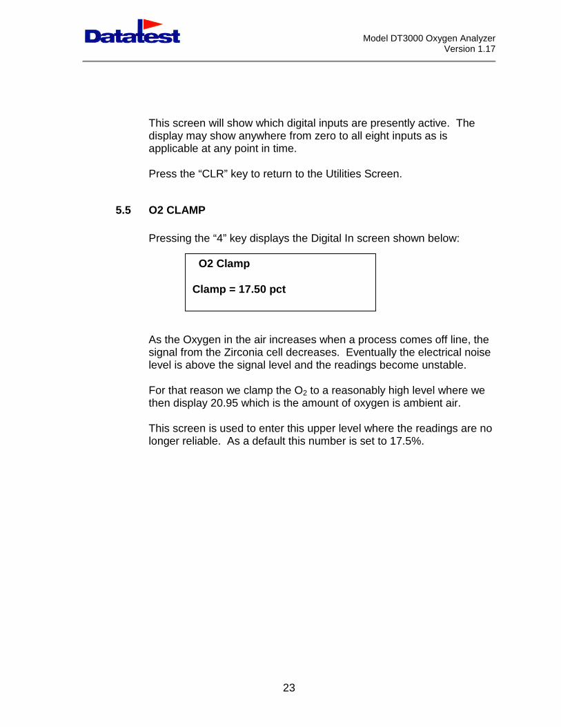
5.5 O2 CLAMP
Pressing the “4” key displays the Digital In screen shown below:
As the Oxygen in the air increases when a process comes off line, thesignal from the Zirconia cell decreases. Eventually the electrical noiselevel is above the signal level and the readings become unstable.
For that reason we clamp the O2 to a reasonably high level where wethen display 20.95 which is the amount of oxygen is ambient air.
This screen is used to enter this upper level where the readings are nolonger reliable. As a default this number is set to 17.5%.
O2 Clamp
Clamp = 17.50 pct
Model DT3000 Oxygen AnalyzerVersion 1.17
24
SECTION 6
STARTUP AND OPERATION
6.1 INTRODUCTION
When the Model DT3000 has been set up as described in section 3, it is thenready for operation. This section describes what the Model DT3000 does andwhat is needed from the operator.
6.2 INITIAL STARTUP
Initially it is suggested that the Model DT3000 be operated with the sameparameters that were in the instrument on arrival. Likewise, the samecalibration can be used that the instrument received during test. This willinsure that there is no problem with the hardware. The following procedure istherefore recommended.
6.3 SET UP PROCEDURE
Start Up
It is suggested that before configuring the instrument for your specific needsyou verify its performance. The test parameters from the factory reside in theinstrument memory; therefore its performance can be verified. The followingprocedure will allow you to verify this performance.
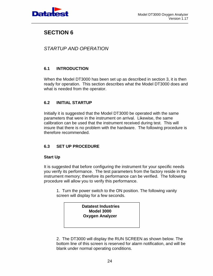
1. Turn the power switch to the ON position. The following vanityscreen will display for a few seconds.
2. The DT3000 will display the RUN SCREEN as shown below. Thebottom line of this screen is reserved for alarm notification, and will beblank under normal operating conditions.
Datatest IndustriesModel 3000
Oxygen Analyzer
Model DT3000 Oxygen AnalyzerVersion 1.17
3. The instrument will proceed with its warm up and stabilizationroutines.
4. Connect the calibration gas line to the insitu O2 sample probe. Setexternal cylinder gas pressures to 2 psi.
6.4 SETTING PARAMETERS
Pressing “CLR” on the keypad brings up the Main Menu shown below.
The instrupressing t
The displa
The bottoaccessedwill scrollwill reversmay haveand they a
BaBaRoIns
O2 =0.00%Avg =0.00%
Temp = 0.00F
MAIN MENU1 - RUN 4 - UTILITIES2 - CALIBRATION
ment operating parameters can be set through the Main Menu byhe “3” key.
y now appears as follows.
3 - SET PARAMETERS
25
m line is the active parameter. Additional parameters can beby pressing the “” key. Each time the “” is pressed the displayand show a new parameter on the bottom line. Pressing the “” keye the direction of the scroll and allow access to a parameter youalready past. There are ten (10) parameters that can be accessedre:
ck Purge Periodck Purge Durationlling Averagetant Average
Back Purge Period
Model DT3000 Oxygen AnalyzerVersion 1.17
Recorder RangeO2 Low Set pointO2 High Set pointCAL. Purge TimeSample & Hold in CALAuto CalibrationSet Time HH:MMComms. Setup
To edit the BACK PURGE PERIOD make sure it is on the bottom line thenpress the “ENT” key. The following prompt will be displayed:
To edit the Back Purge Period (BPP), press the numeric keys that correspondwith the desired time and press “ENT” key to accept this value. Theprogrammable range is 0 minutes to 999 minutes.
This is used only for back purging the stack probe filters. Note that it appliesonly if back purging is to be under control by the Model DT3000 for backpurging the insitu sample probe.
A parameter can be changed, as many times as needed, to make sure it iscorrect. The value retained by the Model DT3000 will be the value presentwhen “ENT” key is pressed (unless the value was out of the acceptablerange).
Advance to the next parameter by pressing the “” key.
The display scrolls up with the bottom line reading Back Purge Duration:
To programprompt will
BPP = 012 min
Back Purge Period
the back pbe displaye
Back Pur
Back Purge Period
26
urge duration press the “ENT” key. The followingd:
ge Duration
Model DT3000 Oxygen AnalyzerVersion 1.17
The Back Pand should
To edit thecorrespondprogramma
Advance to
The display
To programwill be displ
The Rollingdisplayed o
To edit thedesired minPress the “E
The display
Set Back Purge Dur
urge Duration is the time in seconds for the back purge durationbe 0 if a back purge is not desired.
Back Purge Duration (BPD), press the numeric keys thatto the desired time and press “ENT” key to accept this value. Theble range is 1 second to 60 seconds.
the next parameter by pressing the “” key.
scrolls up with the bottom line reading Rolling Average:
ta
An
RuN
s
BPD = 10 seconds
A
Back Purge PeriodBack Purge Duration
he Rolling Average press the “ENT” key. The following promptyed.
Rolling Average
Rolling Average
verage is used to set the rolling average of the O2 reading that isthe Run Screen next to Avg.
olling Average, press the numeric keys that correspond to thetes. The programmable range is from 1 minute to 240 minutes.T” key to accept this value.
crolls up with the bottom line reading Instant Average.
VERAGE = 1 min
Back Purge PeriodBack Purge DurationRolling Average
27
Instant Average
Model DT3000 Oxygen AnalyzerVersion 1.17
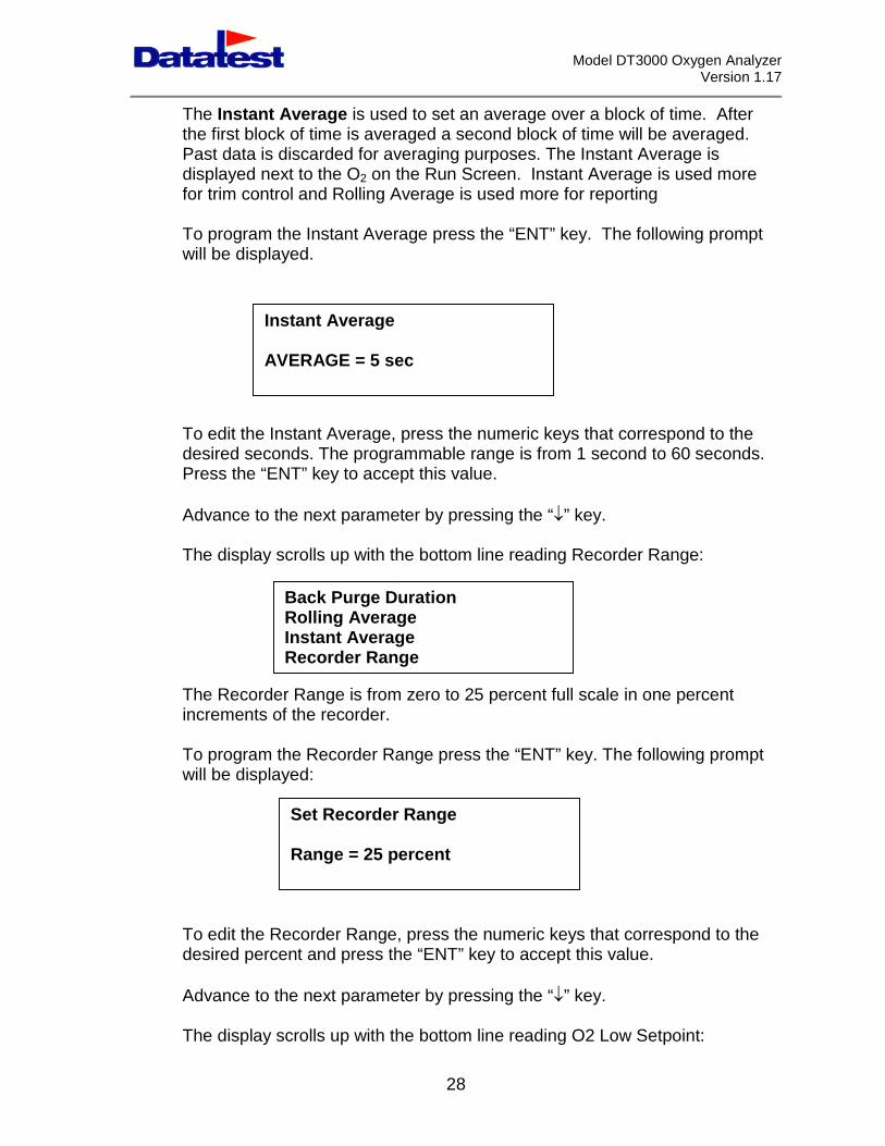
The Instant Average is used to set an average over a block of time. Afterthe first block of time is averaged a second block of time will be averaged.Past data is discarded for averaging purposes. The Instant Average isdisplayed next to the O2 on the Run Screen. Instant Average is used morefor trim control and Rolling Average is used more for reporting
To program the Instant Average press the “ENT” key. The following promptwill be displayed.
To edit the Instant Average, press the numeric keys that correspond to thedesired seconds. The programmable range is from 1 second to 60 seconds.Press the “ENT” key to accept this value.
Advance to the next parameter by pressing the “” key.
The display scrolls up with the bottom line reading Recorder Range:
The Recorder Range is from zero to 25 percent full scale in one percentincrements of the recorder.
To program the Recorder Range press the “ENT” key. The following promptwill be displayed:
To edit the Rdesired perce
Advance to th
The display s
AVERAGE = 5 sec
Back Purge DurationRolling AverageInstant AverageRecorder Range
Set Recorder Range
Instant Average
28
ecorder Range, press the numeric keys that correspond to thent and press the “ENT” key to accept this value.
e next parameter by pressing the “” key.
crolls up with the bottom line reading O2 Low Setpoint:
Range = 25 percent
Model DT3000 Oxygen AnalyzerVersion 1.17
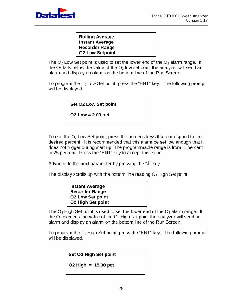
The O2 Low Sthe O2 falls bealarm and disp
To program thwill be display
To edit the O2
desired percendoes not triggeto 25 percent.
Advance to th
The display sc
The O2 High Sthe O2 exceedalarm and disp
To program thwill be display
Set
O2
InsRecO2O2
Set
O2 H
Rolling AverageInstant AverageRecorder Range
29
et point is used to set the lower end of the O2 alarm range. Iflow the value of the O2 low set point the analyzer will send anlay an alarm on the bottom line of the Run Screen.
e O2 Low Set point, press the “ENT” key. The following prompted.
Low Set point, press the numeric keys that correspond to thet. It is recommended that this alarm be set low enough that itr during start up. The programmable range is from .1 percentPress the “ENT” key to accept this value.
e next parameter by pressing the “” key.
rolls up with the bottom line reading O2 High Set point.
et point is used to set the lower end of the O2 alarm range. Ifs the value of the O2 High set point the analyzer will send anlay an alarm on the bottom line of the Run Screen.
e O2 High Set point, press the “ENT” key. The following prompted.
O2 Low Setpoint
O2 Low Set point
Low = 2.00 pct
tant Averageorder RangeLow Set pointHigh Set point
O2 High Set point
igh = 15.00 pct
Model DT3000 Oxygen AnalyzerVersion 1.17
To edit the O2 High Set point, press the numeric keys that correspond to thedesired percent. The programmable range is from .1 percent to 25 percent.Press the “ENT” key to accept this value.
Advance to the next parameter by pressing the “” key.
The display scrolls up with the bottom line reading Cal Purge Time:
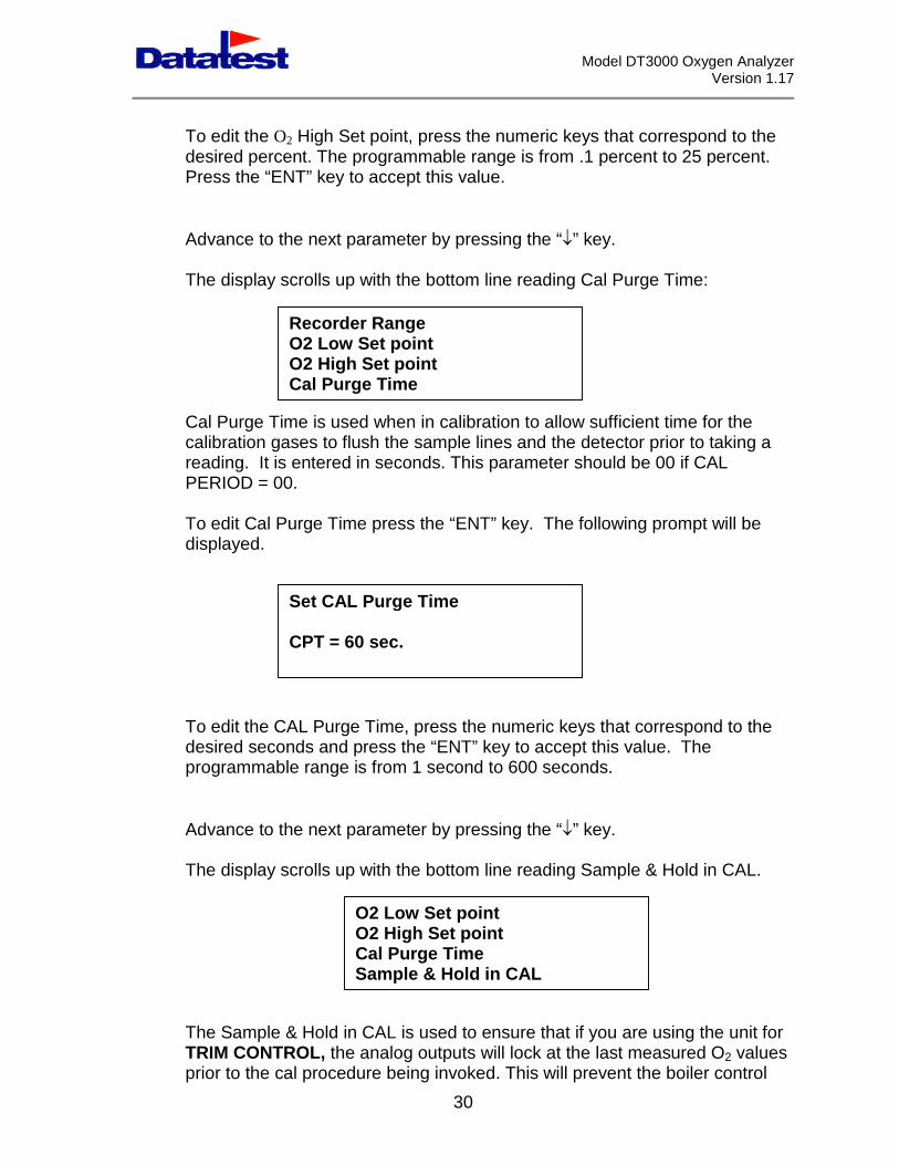
Cal Purge Time is used when in calibration to allow sufficient time for thecalibration gases to flush the sample lines and the detector prior to taking areading. It is entered in seconds. This parameter should be 00 if CALPERIOD = 00.
To edit Cal Purge Time press the “ENT” key. The following prompt will bedisplayed.
To edit the Cdesired secoprogrammab
Advance to
The display
The SampleTRIM CONTprior to the c
Recorder RangeO2 Low Set pointO2 High Set pointCal Purge Time
Set CAL Purge Time
30
AL Purge Time, press the numeric keys that correspond to thends and press the “ENT” key to accept this value. Thele range is from 1 second to 600 seconds.
the next parameter by pressing the “” key.
scrolls up with the bottom line reading Sample & Hold in CAL.
& Hold in CAL is used to ensure that if you are using the unit forROL, the analog outputs will lock at the last measured O2 valuesal procedure being invoked. This will prevent the boiler control
CPT = 60 sec.
O2 Low Set pointO2 High Set pointCal Purge TimeSample & Hold in CAL
Model DT3000 Oxygen AnalyzerVersion 1.17
instrument from being upset by the swings in O2 from Zero to Span as theinstrument executes its cal cycle.
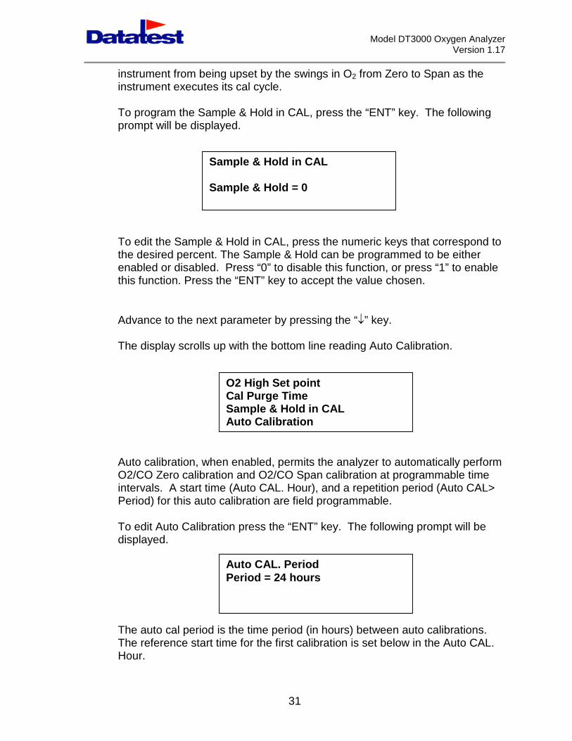
To program the Sample & Hold in CAL, press the “ENT” key. The followingprompt will be displayed.
To edit the Sampthe desired perceenabled or disablthis function. Pres
Advance to the ne
The display scroll
Auto calibration, wO2/CO Zero calibintervals. A startPeriod) for this au
To edit Auto Calibdisplayed.
The auto cal perioThe reference staHour.
Sample & Hold in CAL
31
le & Hold in CAL, press the numeric keys that correspond tont. The Sample & Hold can be programmed to be eithered. Press “0” to disable this function, or press “1” to enables the “ENT” key to accept the value chosen.
xt parameter by pressing the “” key.
s up with the bottom line reading Auto Calibration.
hen enabled, permits the analyzer to automatically performration and O2/CO Span calibration at programmable timetime (Auto CAL. Hour), and a repetition period (Auto CAL>to calibration are field programmable.
ration press the “ENT” key. The following prompt will be
d is the time period (in hours) between auto calibrations.rt time for the first calibration is set below in the Auto CAL.
O2 High Set pointCal Purge TimeSample & Hold in CALAuto Calibration
Sample & Hold = 0
Auto CAL. PeriodPeriod = 24 hours
Model DT3000 Oxygen AnalyzerVersion 1.17
To edit the Auto CAL. Period press the numeric keys that correspond to thedesired hours. The programmable range is from 1 hour to 24 hours.
Press the “ENT” key to accept this value and move to the Auto CAL. Hoursetup screen shown below.
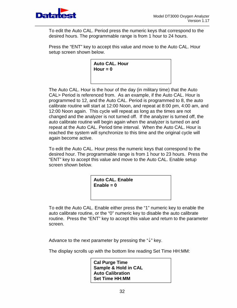
The Auto CAL. Hour is the hour of the day (in military time) that the AutoCAL> Period is referenced from. As an example, if the Auto CAL. Hour isprogrammed to 12, and the Auto CAL. Period is programmed to 8, the autocalibrate routine will start at 12:00 Noon, and repeat at 8:00 pm, 4:00 am, and12:00 Noon again. This cycle will repeat as long as the times are notchanged and the analyzer is not turned off. If the analyzer is turned off, theauto calibrate routine will begin again when the analyzer is turned on andrepeat at the Auto CAL. Period time interval. When the Auto CAL. Hour isreached the system will synchronize to this time and the original cycle willagain become active.
To edit the Auto CAL. Hour press the numeric keys that correspond to thedesired hour. The programmable range is from 1 hour to 23 hours. Press the“ENT” key to accept this value and move to the Auto CAL. Enable setupscreen shown below.
To edit the Auto CAL. Enable either press the “1” numeric key to enable theauto calibrate routine, or the “0” numeric key to disable the auto calibrateroutine. Press the “ENT” key to accept this value and return to the parameterscreen.
Advance to the next parameter by pressing the “” key.
The display scrolls up with the bottom line reading Set Time HH:MM:
Auto CAL. HourHour = 0
Auto CAL. EnableEnable = 0
Cal Purge TimeSample & Hold in CALAuto Calibration
32
Set Time HH:MM
Model DT3000 Oxygen AnalyzerVersion 1.17
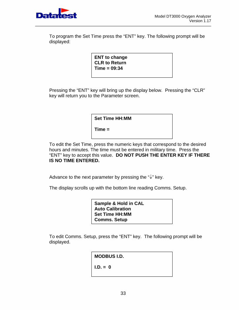
To program the Set Time press the “ENT” key. The following prompt will bedisplayed:
Pressing the “ENT” key will bring up the display below. Pressing the “CLR”key will return you to the Parameter screen.
To edit the Set Time, press the numeric keys that correspond to the desiredhours and minutes. The time must be entered in military time. Press the“ENT” key to accept this value. DO NOT PUSH THE ENTER KEY IF THEREIS NO TIME ENTERED.
Advance to the next parameter by pressing the “” key.
The display scrolls up with the bottom line reading Comms. Setup.
To edit Comms. Setup, press the “ENT” key. The following prompt will bedisplayed.
ENT to changeCLR to ReturnTime = 09:34
Set Time HH:MM
Time =
Comms. Setup
MODBUS I.D.
Sample & Hold in CALAuto CalibrationSet Time HH:MM
33
I.D. = 0
Model DT3000 Oxygen AnalyzerVersion 1.17
When communicating with a remote device (DCS, PC, PLC, etc.), each O2
analyzer must have a unique ID number between 0 and 255.
To edit the Modbus ID, press the numeric keys that correspond to the desirednumber and press the “ENT” key to accept this value.
The following screen will now be displayed:
If the system is commthe analyzer must bothe “0” or “1” key dep
The following screen
If the system is commthe analyzer must bonumeric keys that cokey.
Pressing the clear “the “CLR” key to beMenu screen. The
The selection of ‘1’ frautomatic run mode.measuring O2 levelsparameter routine.
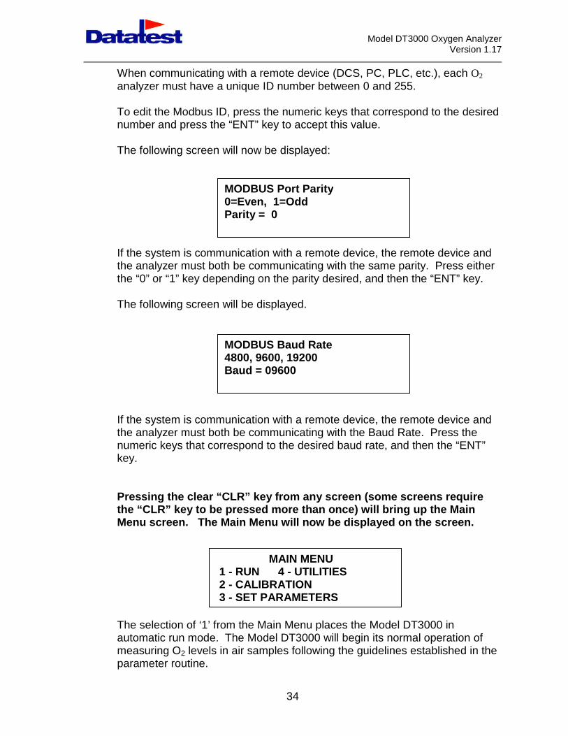
MODBUS Port Parity0=Even, 1=Odd
unication with a remote device, the remote device andth be communicating with the same parity. Press eitherending on the parity desired, and then the “ENT” key.
will be displayed.
Parity = 0
MODBUS Baud Rate4800, 9600, 19200
unication with a remote device, the remote device andth be communicating with the Baud Rate. Press therrespond to the desired baud rate, and then the “ENT”
CLR” key from any screen (some screens requirepressed more than once) will bring up the Main
Main Menu will now be displayed on the screen.
Baud = 09600
MAIN MENU1 - RUN 4 - UTILITIES2 - CALIBRATION
34
om the Main Menu places the Model DT3000 inThe Model DT3000 will begin its normal operation of
in air samples following the guidelines established in the
3 - SET PARAMETERS
Model DT3000 Oxygen AnalyzerVersion 1.17
SECTION 7
CALIBRATION
7.1 INTRODUCTION
A Zirconia sensor based oxygen analyzer needs initial and periodiccalibration, using known test gases, for several reasons.
Initial calibration is required to set the linearization curve for theinstalled conditions.
Periodic calibration to reset linearization due to electronic componentaging, sensor aging, and changes in the flue gas conditions.
For EPA reporting a calibration check is required once every 24 hours.
For trim control a calibration is typically required once every three months, orwhenever a new sensor is installed.
7.2 CALIBRATION
For calibration, connect the Cal gases as described earlier in this manual.
The Zero or Span calibration gases are to be introduced to the calibration portof the Model DT3000 insitu probe at positive pressure. Calibration gas flowrates should be adjusted to around 5 SCFH.
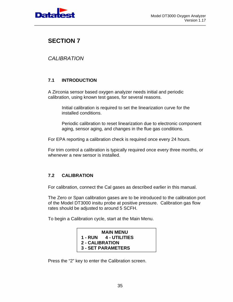
To begin a Calibration cycle, start at the Main Menu.
Press the “2” k
MAIN MENU1 - RUN 4 - UTILITIES2 - CALIBRATION
35
ey to enter the Calibration screen.
3 - SET PARAMETERS
Model DT3000 Oxygen AnalyzerVersion 1.17
From here presAdjust.
To call for a Zewill then appea
The second linthat the purgeseconds, from
The final line isThe number inis entered in thTime has elapsallow samplingdisplay reverts
To complete ththrough the Caopens admittinbe adjusted as
The second linshows that thedown, in secon(See Section 6
The final line isThe number inis entered in th
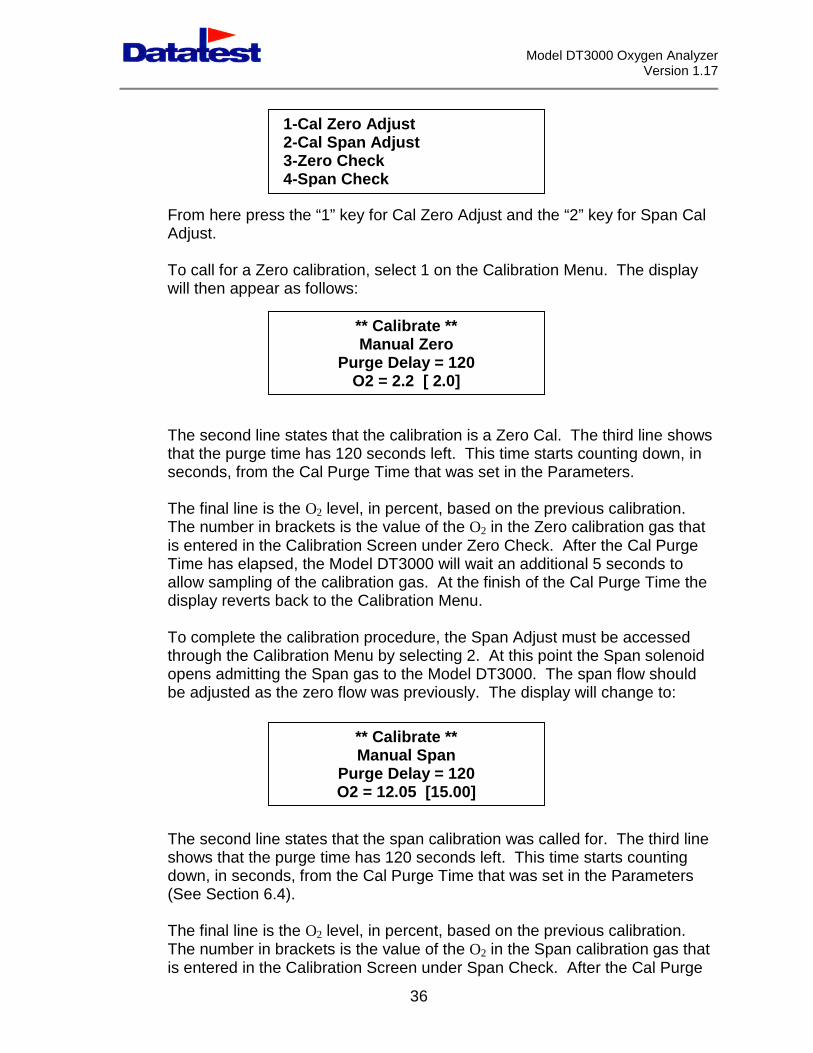
1-Cal Zero Adjust2-Cal Span Adjust3-Zero Check
s the “1” key for Cal Zero Adjust and the “2” key for Span Cal
ro calibration, select 1 on the Calibration Menu. The displayr as follows:
e states thatime has 12the Cal Pur
the O2 levebrackets ise Calibratioed, the Moof the calibback to the
e calibratiolibration Meg the Spanthe zero flo
e states thapurge timeds, from th.4).
the O2 levebrackets ise Calibratio
4-Span Check
P
PO
** Calibrate **Manual Zero
urge Delay = 120
t the calibration is a Zero Cal. The third line shows0 seconds left. This time starts counting down, inge Time that was set in the Parameters.
l, in percent, based on the previous calibration.the value of the O2 in the Zero calibration gas thatn Screen under Zero Check. After the Cal Purgedel DT3000 will wait an additional 5 seconds toration gas. At the finish of the Cal Purge Time theCalibration Menu.
n procedure, the Span Adjust must be accessednu by selecting 2. At this point the Span solenoidgas to the Model DT3000. The span flow shouldw was previously. The display will change to:
O2 = 2.2 [ 2.0]
** Calibrate **Manual Span
urge Delay = 120
36
t the span calibration was called for. The third linehas 120 seconds left. This time starts counting
e Cal Purge Time that was set in the Parameters
l, in percent, based on the previous calibration.the value of the O2 in the Span calibration gas thatn Screen under Span Check. After the Cal Purge
2 = 12.05 [15.00]
Model DT3000 Oxygen AnalyzerVersion 1.17
Time has elapsed, the Model DT3000 will wait an additional 5 seconds toallow sampling of the calibration gas. At the finish of the Cal Purge Time thedisplay reverts back to the Calibration Menu
If the analyzer fails calibration for any reason it reverts back to the pre-calibrate conditions.
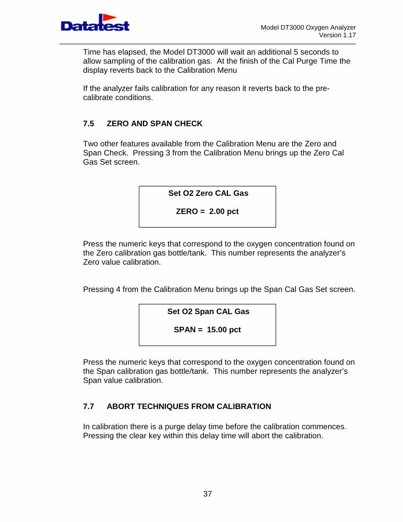
7.5 ZERO AND SPAN CHECK
Two other features available from the Calibration Menu are the Zero andSpan Check. Pressing 3 from the Calibration Menu brings up the Zero CalGas Set screen.
Press the numeric keysthe Zero calibration gasZero value calibration.
Pressing 4 from the Ca
Press the numeric keysthe Span calibration gaSpan value calibration.
7.7 ABORT TECHN
In calibration there is aPressing the clear key
Set O2 Zero CAL Gas
that correspond to the oxygen concentration found onbottle/tank. This number represents the analyzer’s
libration Menu brings up the Span Cal Gas Set screen.
ZERO = 2.00 pct
Set O2 Span CAL Gas
37
that correspond to the oxygen concentration found ons bottle/tank. This number represents the analyzer’s
IQUES FROM CALIBRATION
purge delay time before the calibration commences.within this delay time will abort the calibration.
SPAN = 15.00 pct
Model DT3000 Oxygen AnalyzerVersion 1.17
38
SECTION 8
DIAGNOSTIC DISCUSSION
8.1 INTRODUCTION
During operation up of the Model DT3000 various diagnostic messages mayappear in the display. Each of these messages is discussed below:
8.2 CALIBRATION FAULT
If during the calibration period the analyzer detects an O2 value less than 6points below the calibration gas value, or 6 points above the calibration gasvalue. A “Calibration Fault” alarm message will appear on the bottom line ofthe Run screen to indicate the analyzer is out of calibration.
The on board alarm contact will close during this alarm condition providing ameans for remote alarm indication.
8.3 HIGH SENSOR TEMP
If the temperature of the Zirconia sensor exceeds the analyzer’s preset upperlimit a “High Sensor Temp” alarm message will appear on the bottom line ofthe Run screen to indicate the analyzer is out of calibration.
The on board alarm contact will close during this alarm condition providing ameans for remote alarm indication.
In addition to the above the analyzer will attempt to reduce the temperature ofthe Zirconia cell. If the temperature returns to normal the alarm will clear.
8.4 LOW SENSOR TEMP
If the temperature of the Zirconia sensor falls below the analyzer’s presetlower limit a “Low Sensor Temp” alarm message will appear on the bottomline of the Run screen to indicate the analyzer is out of calibration.
The on board alarm contact will close during this alarm condition providing ameans for remote alarm indication.

Model DT3000 Oxygen AnalyzerVersion 1.17
39
In addition to the above the analyzer will attempt to increase the temperatureof the Zirconia cell. If the temperature returns to normal the alarm will clear.

Model DT3000 Oxygen AnalyzerVersion 1.17
40
SECTION 9
INSTRUMENT DESCRIPTION
9.1 INTRODUCTION
The Model DT3000 microprocessor controller contains features necessary tomaintain the oxygen sensor at its operating temperature, and to displayvalues corresponding to percentage of oxygen in the flue gas.
The Model DT3000 comes with a 4-line, 80-character LCD display and a 16-key membrane keypad. User interface is through the keypad and LCDdisplay, which displays measurements, system status messages, and alarms.Sensor calibration is also initiated through the keypad.
9.2 O2 CELL ANALOG CIRCUIT
The Zirconia cell provides a current output that is conditioned and amplified toprovide a voltage output to a microprocessor.
The signal from the Zirconia cell is in the form of a very low ion current.
9.3 O2 CELL THERMOCOUPLE CIRCUIT
A type K thermocouple is inserted into the center of the Zirconia cell formonitoring cell temperature. This thermocouple provides a voltage that isproportional to the temperature of the Zirconia cell. A typical cell temperatureis 1000°F to provide a thermocouple output of 22.250 mV. The resistance ofthe thermocouple is approximately 2 ohms at 70°F when disconnected.
The O2 cell thermocouple voltage signal is conditioned and amplified toprovide a voltage output to a microprocessor
9.4 RELAY OUTPUTS
The Model DT3000 provides relay outputs (SPST) for low and high set pointalarms, system fault and back purge. These relay outputs are provided on
Model DT3000 Oxygen AnalyzerVersion 1.17
41
TB1 located on the back panel of the enclosure. All relay contacts areNormally Open (N.O.) and will provide a contact closure when energized.
9.5 INPUTS
The Model DT3000 has digital inputs for initiating a remote zero and spanprocedure. 120VAC applied to the appropriate input will induce theappropriate procedure.
Model DT3000 Oxygen AnalyzerVersion 1.17
42
SECTION 10
OXYGEN SENSOR
10.1 OXYGEN SENSOR - GENERAL
The oxygen sensor consists of a Zirconia oxide sensor, which is threaded intothe sample cell. The sensor consists of two component groups, sensorexterior (air reference) and inner sensor (sample). It creates an electricalsignal when oxygen level on the sample side of the cell is not equal to oxygenlevels on the reference airside. This signal is proportional to the difference inoxygen levels.
10.2 ZIRCONIA SENSOR ASSEMBLY
The O2 cell comprises of a Zirconia oxide sensor and a type-K thermocoupleinserted into the center of the Zirconia sensor. A heater element surroundsthe Zirconia sensor and maintains the Zirconia cell at about 1000°F. Airreference holes are provided at the top of the Zirconia sensor.
The complete Zirconia cell with thermocouple, threads into the sample cell fordirect measurement of flue gas (insitu-wet), or conditioned sample gas(extractive-dry).
Model DT3000 Oxygen AnalyzerVersion 1.17
43
SECTION 11
TROUBLE SHOOTING
11.1 OVERVIEW
The system troubleshooting section is divided into two parts that describehow to identify and isolate oxygen analyzer faults. The first part describessensor faults and the second describes electronic faults. The alarms andmessages caused by either may overlap.
11.2 SPECIAL TROUBLESHOOTING NOTES
a. Grounding: It is essential that adequate grounding precautions are takenwhen system is being installed. Thoroughly check all grounding connectionsbefore and after faultfinding.
b. Loose Integrated Circuits: The electronics uses a microprocessor andsupporting integrated circuits. Should the electronics receive rough handlingduring installation, or is installed in a location that is subject to severevibration, an integrated circuit (IC) could work loose. Make sure all IC’s arefully seated before system troubleshooting begins.
11.3 SENSOR TROUBLESHOOTING
a. Sensor Faults: Listed below are three symptoms of sensor failure.
1. The system does not respond to changes in oxygenconcentration.
2. The system responds to changes in oxygen concentration,but does not give correct indication.
3. The system does not give an acceptable indication of thevalue of the test gas being applied during calibration.
b. Fault Finding: The following Table is a guide for finding faults ofthe above symptoms.
Model DT3000 Oxygen AnalyzerVersion 1.17
44
MALFUNCTION POSSIBLEFAILURE
CHECK REMEDY
Heater is cold andT/C mV output isless than setpoint.
Thermocouple Thermocouplecontinuity Checkelectricalconnections /Thermocouplepolarity
Replace T/C or replaceZirconia sensor. Correctwiring
Fuse Blown Check Fuse Replace fuse.
Solid state relayto heater
Failure ofelectronics or S.SRelay
Replace mother board orsolid state relay
Heater is hot andT/C mV output isat set point.
No cell mV atsensor.
Cell mV input toelectronics andmV at sensorhead.
Replace Zirconia sensor.
Sensor mVnormal but noinput toelectronics.
Cable connection. Check cable connection.
Cell mV normalat sensor headand input toelectronics
Failure ofelectronics
Replace oxygen PCB andreturn faulty board toDatatest.
Model DT3000 Oxygen AnalyzerVersion 1.17
45
11.4 ELECTRONICS TROUBLESHOOTING
The Model DT3000 has on-board diagnostic features, which aid faultfinding.Normally the user will not need to use electronic testing equipment in faultdiagnostic. Almost all reasons for system malfunction are displayed by eitheran alarm or a fault message on the liquid crystal display.
MALFUNCTION POSSIBLEFAILURE
CHECK REMEDY
System respondsto oxygenconcentrationchanges but doesnot give correctreading.
Calibration error. Systemcalibration.
Recalibrate system.
Vacuum leak. Airgetting in sampleline
Extractivesystem.
Stop air leak.
. Check sampleline and fittings.
Leaky zero, spanor back purgesolenoid
Check backpurge and calsolenoids.
Stop solenoid leak.
Failure ofelectronics.
Cell mV input toelectronics.
Replace oxygen PCB andreturn faulty board toDatatest.
System does notgive accurateindication ofapplied test gas.
Blocked sampleline.
Test sample inletport.
Verify calibrationgasconcentrations.
Clean port.
Replace calibration gascontainer.
Model DT3000 Oxygen AnalyzerVersion 1.17
46
11.5 ALARM MESSAGES
The Model DT3000 has various diagnostic alarm features, which may appearin the display.
Low Sensor TempHigh Sensor Temp
BackpurgeThermocouple FaultCalibration FaultRemote Calibration
Each of these alarm messages is discussed in this manual.
Model DT3000 Oxygen AnalyzerVersion 1.17
47
SECTION 12
SERVICE AND NORMAL MAINTENANCE
12.1 OVERVIEW
This section describes routine maintenance of the Model DT3000 OxygenAnalyzer. Spare parts referred to are available from Datatest. Observewarning and caution labels.
12.2 PRELIMINARY CHECKS
The following preliminary checks will help isolate problems in the analyzer.Run these checks before beginning any repair work. Check parameter anddisplays according to instructions in Section 4, System Startup.
WARNING: Wear heat resistance gloves when handling hot sensor andanalyzer parts. The parts may be hot enough to cause severe burns.
a. Check Display for Alarms: Go through normal power upprocedure. Allow enough time for sensor to reach proper temperature.Check display for alarms. If there are alarms, troubleshoot.
b. Run Calibration Check: Run calibration check procedureaccording to section 7. If calibration is successful, no problem exists.If calibration fails, shut off power and make sure that all wires and gaslines are properly connected to analyzer. If everything checks outproperly, proceed to step c.
c. Check Thermocouple Output: Turn power on. Checkthermocouple mV output. It should be at the mV set point (22.25 mV+/- 0.2 mV). If output is incorrect, check heater fuse. If fuse is good,check heater and thermocouple resistance as follows.
1. Measure heater resistance. Measure resistance of heaterelement at heater terminal on O2 Sensor Assembly. Theresistance should be less than 2 ohms. If heater element isopen circuit, replace sensor heater element in sample cell.
Model DT3000 Oxygen AnalyzerVersion 1.17
48
2. Measure thermocouple resistance. Measure thethermocouple resistance on top of the Zirconia sensor locatedon the sample cell or O2 insitu head. The resistance of thethermocouple should be approximately 2 ohms at 70°F.
12.3 SENSOR CALIBRATION:
The Datatest Model DT3000 Oxygen Analyzer should be calibrated wheninstalled. Under normal operation, sensor will not require frequent calibration.When calibration is required, follow the procedures in section 7.
12.4 SENSOR REMOVAL AND INSTALLATION:
SENSOR REMOVAL: This paragraph covers the oxygen sensor removalfrom the sample cell or insitu head. Use the following procedure to removesensor from the Model DT3000 for repair or replacement.
1. Disconnect and turn off AC power to the O2 control unit. Shut off allcalibration gases. Do not attempt to work on sensor assembly until itas cooled to a comfortable working temperature.
2. Disconnect sample gas tubing, reference gas tubing, back purgeand exhaust tubing to casting of O2 sensor assembly.
3. For rack mount units, remove screws from front panel securingsensor assembly to panel. Remove sensor assembly. For Insitu units,remove O2 probe assembly cover plate from air reference cell toexpose Zirconia sensor.
4. Disconnect thermocouple wire extension, cell wires and heaterwires from sensor ceramic connectors.
5. Using a 7/8” wrench, remove Zirconia sensor from its threaded port.
SENSOR INSTALLATION: Use the following procedure to install Zirconiasensor into the Model DT3000.
1. Using a 7/8” wrench, thread Zirconia sensor into casting of O2 cell.
2. Connect type K thermocouple extension wires, cell wires and heaterwires to ceramic connectors as follows:
TB1/6 THERMOCOUPLE (+) YELTB1/7 THERMOCOUPLE (-) RED
Model DT3000 Oxygen AnalyzerVersion 1.17
49
TB1/4 CELL SIGNAL (+)TB1/5 CELL SIGNAL (-)
TB1/25 Heater – pulsed 10 VACTB1/26 Heater – pulsed 10 VAC
3. For extractive units, secure sensor assembly to front panel ofcontrol unit, or remote location as applicable. For Insitu units, replaceO2 probe assembly cover plate over the casting on the Insitu probe.
4. Connect sample gas tubing, reference gas tubing, back purge, andexhaust tubing to casting of O2 sensor assembly.
5. Connect sensor thermocouple extension wire, cell signal wires, andheater wires to control unit as specified in 2 above.
12.5 HEATER ELEMENT REPLACEMENT
The heater element surrounds the threaded tip of the Zirconia sensor.Should this element fail for any reason, the Sensor housing assemblyshould be sent to Datatest for repair.
12.7 SPARE PARTS
Spare Parts List----------------------------------------------------------------------------------------PART NUMBER DESCRIPTION QUANTITY----------------------------------------------------------------------------------------DK5020 Zirconia Sensor Unit 1
Including thermocouple assembly
300-TRH Heater Transformer 8-10 1
DK5029 Solid State Relay (SSR), 10 Amp 1
3AG Fuse, 2 amp 1BLF3 Fuse, 3 amp
DT3000-PCB Main Controller Card 1
---------------------------------------------------------------------------------------
Model DT3000 Oxygen AnalyzerVersion 1.17
50
13 WARRANTY
Datatest guarantees this system for a period of eighteen (18) months fromdate of installation to be free from defects in material and workmanship.
Our obligation under this guarantee is limited to repairing or replacing anyinstrument or part thereof which shall, within the above specified time, bereturned to us with transportation charges prepaid, and prove after ourexamination to be thus defective. Should the product be found not to bedefective a diagnostic and recalibration charge will apply.
The gas sensor element is excluded from this warranty.
In the event that the customer requires a Datatest field service technician orengineer on site, the customer will be billed for this service at our standardrate. This applies whether the equipment is in or out of warranty. This dailyrate is based on the man-days spent ‘on site’, plus travel time. Expenses fortravel and living are billed at cost.
Datatest personnel will not accept instruments returned under this warranty,to the Datatest plant, without prior authorization.
The user must prepay Freight for Returned Equipment. Datatest willassume the cost of shipping the unit back to the user by common carrier. Ifthe user wishes it returned by other means, the user will be billed for theadditional charges.
We reserve the right to discontinue instruments without notice, and to makemodifications in design at any time without incurring any obligation to makesuch modifications to instruments previous sold.
13.1 RETURNING EQUIPMENT TO THE FACTORY
If factory repair of equipment is required, proceed as follows.
a. Secure a return authorization number from a Datatest Sales Office beforereturning the equipment. Equipment must be returned with completeidentification in accordance with Datatest instructions or it will not beaccepted.
In no event will Datatest be responsible for equipment without properauthorization and identification.
Model DT3000 Oxygen AnalyzerVersion 1.17
51
b. Carefully pack the equipment in a sturdy box with sufficient shockabsorbing material to insure that no additional damage will occur duringshipping.
c. In a cover letter, describe completely:
1. The symptoms that made you think the equipment is faulty.
2. The environment in which the equipment has been operating (i.e.temp, corrosive gasses, moisture, etc.).
3. Name of your company and plant name where equipment wasremoved.
4. Plant contact and phone number.
5. Whether warranty service or non-warranty service is expected.
6. Complete shipping instructions for return of equipment.
d. Enclose the cover letter and purchase order and ship the equipmentaccording to instructions provided in Datatest Return Authorization, prepaidto:
DATATEST Inc.300 Valley RoadHillsborough, NJ 08844TEL: (908) 369-1590FAX: (908) 369-1594
If warranty service is requested, the unit will be carefully inspected and testedat the factory. If failure was due to conditions listed in the standard Datatestwarranty, the unit will be repaired or replaced at Datatest option, and anoperating unit will be returned to the customer in accordance with shippinginstructions furnished in the cover letter.
For equipment no longer under warranty, the equipment will be repaired at thefactory and returned as directed by the purchase order and shipping instructions.
Model DT3000 Oxygen AnalyzerVersion 1.17
52
14 Modbus Registers
Operating information and status of the DT3000 can be sent to a remotecomputer/DCS/PLC via Modbus RTU protocol. The following are the registerdescriptions.
Diagnostic registers
40001 Message Counter. This register increments for every validreceived message.
40002 Read register (03) message counter. This register isincremented for every received message that is a read holdingregister command.
40003 Invalid CRC message counter. This register is incremented formessages that have been received with a bad CRC.
40004 Exception response message counter. This register isincremented when the instrument transmits a MODBUSexception response.
40005 Reserved
40006 Last exception code. This register holds the last exception codethat was transmitted.
40007-9 Reserved
40010-17 Last exception response message. Eight registers holding thecharacter data of the last exception response that wastransmitted.
System Registers
40021 Back purge timer. The incrementing back purge timer value inminutes.
40022 Back purge flag. Value equals 1 when the instrument isperforming a back purge otherwise it is zero.
40023 System Status.
Model DT3000 Oxygen AnalyzerVersion 1.17
53
40031 O2 instantaneous reading. The register is an integer value. Theoxygen reading is multiplied by 100 to give an integer value inincrements of hundredths. This is the fastest changing O2 value. Thevalue is in the range of 0 to 2500.
40032 O2 instantaneous average reading. The register is an integer value ofthe “instantaneous” rolling seconds average. The O2 reading ismultiplied by 100 to give an integer value in increments of hundredths.The value is in the range of 0 to 2500.
40033 O2 average reading. The register is an integer value of the minuterolling average. This O2 reading is multiplied by 100 to give aninteger value in increments of hundredths. This is the slowestchanging O2 value. The value is in the range of 0 to 2500.
40034-35 O2 instantaneous reading. These registers hold a floating-point value.This is the fastest changing O2 value.
40036-37 O2 instantaneous average reading. These registers hold a floating-point value of the “instantaneous” rolling seconds average.
40038-39 O2 average reading. These registers hold a floating-point value of the“averaged” minute rolling average. This is the slowest changing O2value
Model DT3000 Oxygen AnalyzerVersion 1.17
54
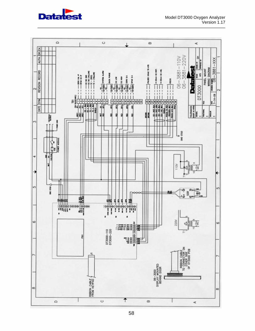
Appendix I – Drawings for Insitu Unit, Panel MountControl Unit
The reduced size drawings on the following pages are provided as typical for thespecific design stated above. Larger drawings and/or electronic drawings areprovided for the actual design purchased.
DT3000-05, Oxygen ProbeDT3000-06, Panel Mount OverviewDT3000-07, Oxygen Probe Overview06-3881-XXXX, Panel Mount Wiring Diagram
Model DT3000 Oxygen AnalyzerVersion 1.17
55
Model DT3000 Oxygen AnalyzerVersion 1.17
56
Model DT3000 Oxygen AnalyzerVersion 1.17
57
Model DT3000 Oxygen AnalyzerVersion 1.17
58
Model DT3000 Oxygen AnalyzerVersion 1.17
59
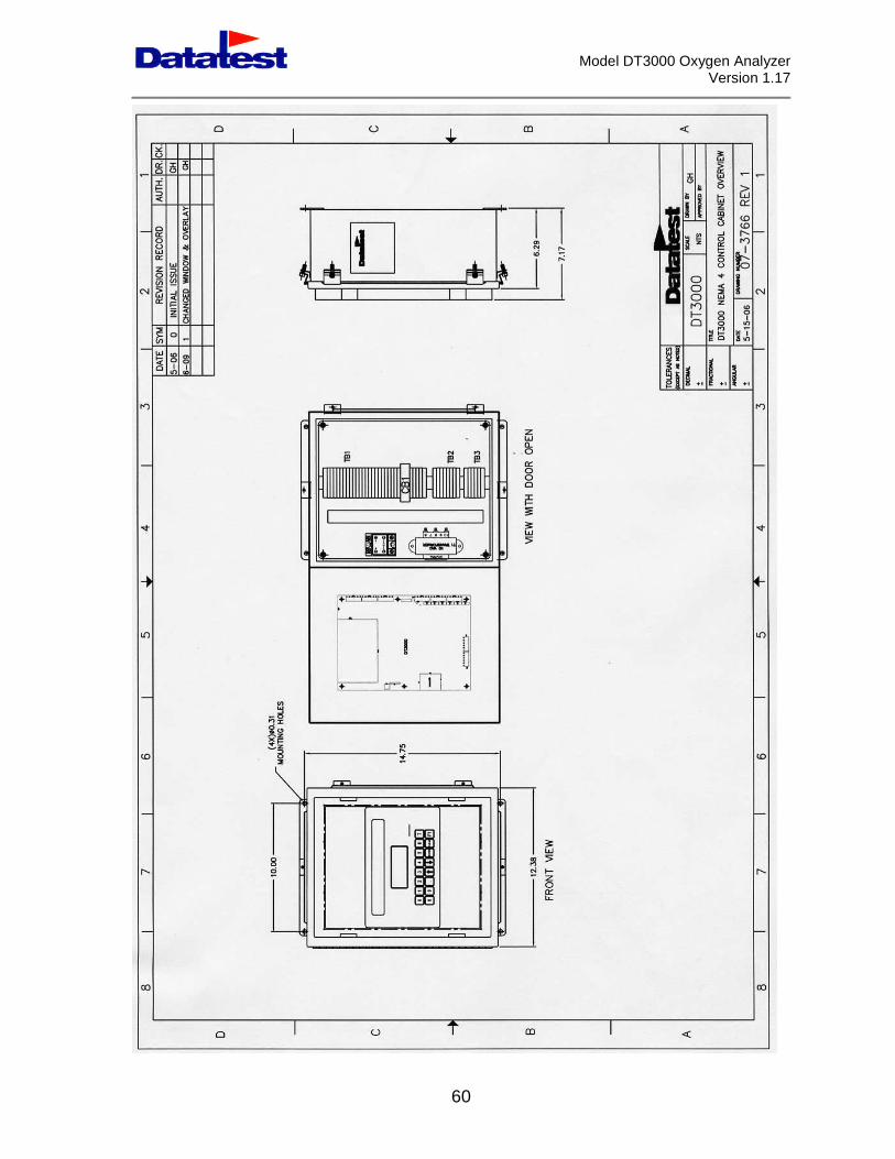
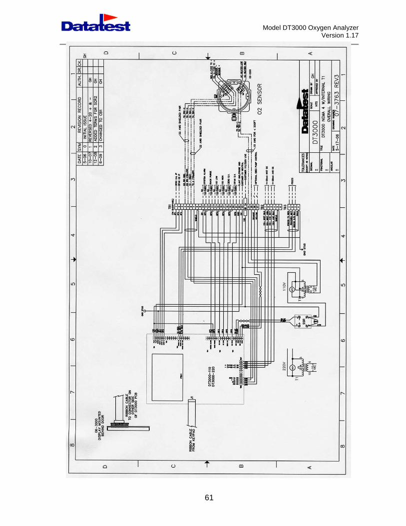
Appendix II – Drawings for Insitu Unit, NEMA 4Control Unit
The reduced size drawings on the following pages are provided as typical for thespecific design stated above. Larger drawings and/or electronic drawings areprovided for the actual design purchased.
07-3766 Rev. 1 Control Cabinet Overview07-3763 Rev. 3 Overall Wiring
Model DT3000 Oxygen AnalyzerVersion 1.17
60
Model DT3000 Oxygen AnalyzerVersion 1.17
61
Model DT3000 Oxygen AnalyzerVersion 1.17
62
Appendix III – Drawings for Extractive Rack MountControl Unit
The reduced size drawings on the following pages are provided as typical for thespecific design stated above. Larger drawings and/or electronic drawings areprovided for the actual design purchased.
B02-3712 Sample ProbeDT3000-04 Rev. 1 Rack Mount Overview & Connections06-3879 Wiring Diagram
Model DT3000 Oxygen AnalyzerVersion 1.17
63
Model DT3000 Oxygen AnalyzerVersion 1.17
64
Model DT3000 Oxygen AnalyzerVersion 1.17
65
Model DT3000 Oxygen AnalyzerVersion 1.17
66
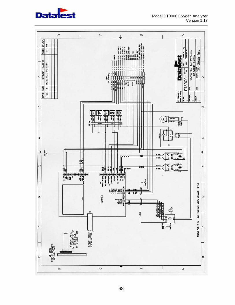
Appendix IV – Drawings for Self Contained ControlUnit
The reduced size drawings on the following pages are provided as typical for thespecific design stated above. Larger drawings and/or electronic drawings areprovided for the actual design purchased.
07-3803 Rev. 1 Analyzer Overview06-3800 Wiring Diagram

Model DT3000 Oxygen AnalyzerVersion 1.17
67
Model DT3000 Oxygen AnalyzerVersion 1.17
68